correlation for prediction of dynamic … turbine inlet valves are used to control the power output...
TRANSCRIPT

Proceedings of the 1st Global Power and Propulsion Forum GPPF 2017
Jan 16-18, 2014, Zurich, Switzerland www.pps.global
This work is licensed under a Creative Commons Attribution-NonCommercial-NoDerivatives 4.0 International License
GPPF-2017-5
CORRELATION FOR PREDICTION OF DYNAMIC FLUID FORCES IN STEAM TURBINE INLET VALVES
C. B. Domnick University of Duisburg-Essen [email protected]
Duisburg, Germany
D. Brillert University of Duisburg-Essen
[email protected] Duisburg, Germany
H. J. Dohmen University of Duisburg-Essen [email protected]
Duisburg, Germany
C. Musch Siemens AG
[email protected] Mülheim an der Ruhr, Germany
F.-K. Benra University of Duisburg-Essen
[email protected] Duisburg, Germany
ABSTRACT
Steam turbine inlet valves are used to adjust the power
output of turbines by reducing the steam turbine inlet
pressure. During the throttling process, the pressure is
reduced and hence enthalpy of the steam is converted to
kinetic energy being dissipated by various processes. Most of
the kinetic energy is re-converted to enthalpy but a small
amount is transformed to pressure fluctuations acting on the
valve plug and other interior parts. In some operating points,
the moveable plug is likely to show vibrations.
As several research studies report, flow induced
vibrations are often causing valve failures. Hence flow
induced dynamic forces acting on the valve plug have to be
considered during the design process. Typically, steam
turbines are designed according to customer requirements.
Hence the inlet conditions, the mass flow rate as well as the
operating curve of steam valves vary significantly among
different steam turbine installations.
The dynamic forces can be predicted with unsteady CFD
calculations but the effort is quite high. Large computational
resources are required to conduct the unsteady CFD
calculation of one single operating point. Hence there is a
demand for correlations that can be used to predict the
dynamic forces.
As the dynamic forces not only depend on the operation
conditions but also on the flow topology inside the valve,
developing these correlations requires a complex scheme.
The paper presented here shows the dependency of the
dynamic forces on the operation conditions as well as the
impact of the topology existing in the valve. Unsteady CFD
calculations using the SAS-turbulence model with zonal
forcing are conducted to calculate the flow field and the
dynamic forces. The physics causing the different flow
topologies are analysed and the prediction method for the
dynamic forces is developed considering both the operational
conditions and the flow topology.
INTRODUCTION
Steam turbine inlet valves are used to control the power
output of large steam turbines. Two effects reduce the power
output of the steam turbine if the flow is throttled by the
valve. The mass flow rate is reduced by the flow constriction
in the valve and the exergy of the fluid is reduced by the
dissipation process in the valve diffuser. The dissipation of a
typical steam turbine inlet valve can reach a range of several
tens of megawatts. Depending on the design of the valve, a
certain amount of the dissipated energy is converted to
pressure fluctuations and hence to vibrations.
If the vibrational stress exceeds the fatigue limit of the
valve’s components damages occur which lead to an outage
of the turbine. For instance Kostyuk et al. [1] report the
damage to nozzle boxes and valve seats, Michaud et al. [2]
describe cracks in the piping of a steam dump system caused
by acoustic fatigue and Zhang et al. [3] report of a valve stem
rupture. Hence it is indispensable to know the limits for safe
operation and the physics behind valve vibrations.
As the thermodynamic boundary conditions, the lift of
the valve plug and also the flow topology vary during the
throttling process, the aerodynamics and the structural
dynamics of a valve have to be investigated at different
operation points.
Literature Review
A brief study of the literature shows that several effects
generating pressure fluctuations resulting in valve vibrations
and noise exist in steam valves. As various valve types are
used, a universal theory that explains valve vibrations in
general does not exist. But there are some basic principles,
which are common among different valve types. At throttled
operation, valves form a flow constriction in which the flow

2
is accelerated by a pressure difference. This constriction can
be for instance the gap between a valve seat and a valve plug.
Enthalpy is converted into kinetic energy by the acceleration
of the flow. In many cases this process is quasi isentropic. In
a second step the kinetic energy is dissipated. This step
causes an increase in entropy and enthalpy. According to
Pluviose [4] the kinetic energy is degraded in dissipative
structures which can cause harmful flow instabilities.
One way to reduce kinetic energy is viscous friction.
Several valve designs utilize perforated installations or
mufflers providing a large surface at which the kinetic
energy is dissipated. For instance, Grotloh [5] describes that
low sound levels are obtained when the flow is throttled in a
hollow cylinder of sintered steel globules. Wagner [6] shows
that the use of different devices forming flow labyrinths
reduces the noise generation. Instabilities can effectively be
avoided by these devices, but usually they also generate large
pressure losses at the open valve position which are
undesired as the losses reduce the efficiency of the steam
turbine plant at full load operation.
Another structure that dissipates kinetic energy is the
shear layer. Shear layers are formed between high speed jets
and the surrounding fluid. Viscous friction as well as the
generation of turbulent vortices reduce the kinetic energy.
Depending on the flow conditions, a jet can be more or less
stable. An experimental study of Heymann and Statiano [7]
shows, that an attached annular wall jet (annular flow) in a
steam valve diffuser creates less sound than a detached jet in
the center of the diffuser (core flow). Numerical
investigations by Domnick et al. [8] show that the dynamic
transverse forces increase when the annular wall jet
separates.
In case of supersonic flow conditions shocks can exist
which dissipate kinetic energy. Serveral studies (Stastny et
al. [9], Zhang and Engeda [10]) show that unsteady shocks
can produce strong dynamic loads and hence valve
vibrations.
Flow impingement on a wall is a dissipative process as
well. The jet splits up, and a highly complex turbulent flow
field generating pressure fluctuations exists. This process is
observed in some valves. The studies of Ziada and Bühlmann
[11] and Nakano [12] show, that impinging jets can produce
vibrations.
Besides the flow topologies occurring in valves also the
thermodynamic boundary conditions, determining the
amount of the dissipated energy, influence the vibrational
level. Hence, some scaling rules for valve noise are based on
the dissipated energy. The concept of the acoustic efficiency
𝜂𝑎𝑐 based on the dissipation is developed by Graf et al. [13].
It is validated in model tests with different model sizes using
steam at different conditions and compressed air. The
acoustic power 𝑃ac is divided by the dissipation J caused by
an isenthalpic expansion from the inlet to the outlet. The
dissipation is formulated by an integration as the temperature
𝜃 is not proportional to the enthalpy h due to real gas effects
existing at typical operation conditions. The acoustic power
is computed from the sound pressure �́�, the acoustic
impedance z, the reference area A and the Mach number Ma.
The study of Graf et al. [13] shows that the pressure ratio 𝜋 is
the similarity parameter for the investigated geometry.
𝜂ac = 𝑃ac
𝐽=
𝑃ac
�̇� ∙ ∫ 𝜃|ℎ=const. d𝑠out
in
(1)
𝑃ac =�́�2 ∙ 𝐴
𝑧∙ (𝑀𝑎 + 1)2 (2)
𝜋 =𝑝out
𝑝in
(3)
Design of the Valve
The valve design investigated in this study is a typical
design of a control valve as used in large power stations. A
sketch of the valve is shown in fig. 1. The red curve marks
the outline of the computational domain shown in fig. 2. The
flow coming from the valve chest (A) passes by four flow
straighteners (B) (only shown in fig. 2). After this, the flow is
throttled in the gap formed between the valve plug (C) and
the valve seat (D). Then it flows through the diffuser (E) of
the valve to the turbine. The back cavity (F) behind the can
shaped valve plug (C) is connected by four bores (G) to the
main flow path. Piston rings (H, only shown in fig.1) are
used to damp vibrations and to avoid leakage flows.
Fig. 1: Sketch of the valve design at middle lift position. Not
to scale
Fig.2: Computational domain
METHODOLOGY
The numerical investigations are performed using the
commercial code Ansys® CFX 15. This code applies a fully
coupled implicit Navier-Stokes solver. A simpler and hence
more efficient Euler code would neglect viscous effects
which are relevant to the investigated subject although the
Reynolds number is high. For instance, the generation and
dissipation of turbulent vortices and the dissipation of wall
jets are influenced by viscosity.
The finally chosen transient numerical set up is second
order accurate in time and space. The computational domain
ACD E
F
G
H
C AB
D
E
F G
3
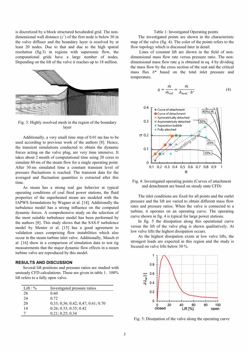
is discretized by a block structured hexahedral grid. The non-
dimensional wall distance (y+) of the first node is below 30 in
the valve diffuser and the boundary layer is resolved by at
least 20 nodes. Due to that and due to the high spatial
resolution (fig.3) in regions with supersonic flow, the
computational grids have a large number of nodes.
Depending on the lift of the valve it reaches up to 18 million.
Fig. 3: Highly resolved mesh in the region of the boundary
layer
Additionally, a very small time step of 0.01 ms has to be
used according to previous work of the authors [8]. Hence,
the transient simulations conducted to obtain the dynamic
forces acting on the valve plug, are very time intensive. It
takes about 2 month of computational time using 20 cores to
simulate 80 ms of the steam flow for a single operating point.
After 30 ms simulated time a constant transient level of
pressure fluctuations is reached. The transient data for the
averaged and fluctuation quantities is extracted after this
time.
As steam has a strong real gas behavior at typical
operating conditions of coal fired power stations, the fluid
properties of the superheated steam are modeled with the
IAPWS formulations by Wagner et al. [14]. Additionally the
turbulence model has a strong influence on the computed
dynamic forces. A comprehensive study on the selection of
the most suitable turbulence model has been performed by
the authors [8]. This study shows that the SAS-F turbulence
model by Menter et al. [15] has a good agreement to
validation cases comprising flow instabilities which also
occur in the steam turbine inlet valve. Additionally, Musch et
al. [16] show in a comparison of simulation data to test rig
measurements that the major dynamic flow effects in a steam
turbine valve are reproduced by this model.
RESULTS AND DISCUSSION
Several lift positions and pressure ratios are studied with
unsteady CFD calculations. These are given in table 1. 100%
lift refers to a fully open valve.
Lift / % Investigated pressure ratios
28 0.60
24 0.72
20 0,33; 0,36; 0,42; 0,47; 0.61; 0.70
14 0.26; 0.33; 0.35; 0.42
7 0.21; 0.25; 0.34
Table 1: Investigated Operating points
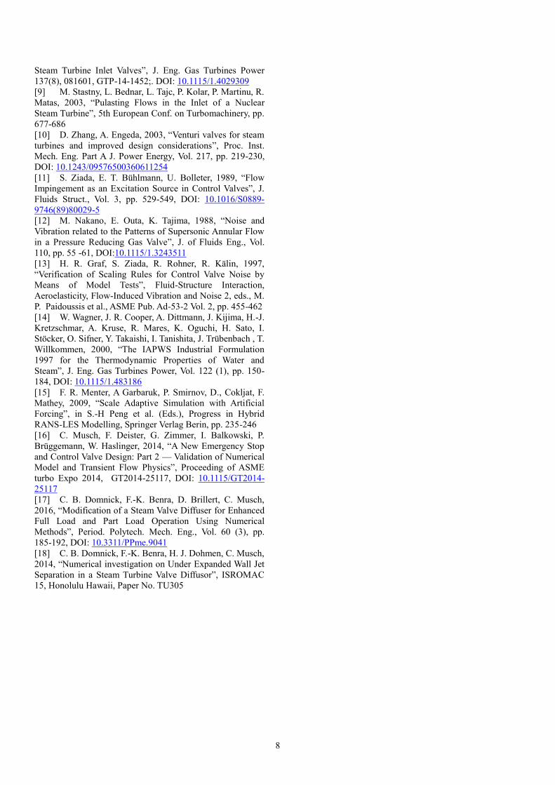
The investigated points are shown in the characteristic
map of the valve (fig. 4). The color of the points refers to the
flow topology which is discussed later in detail.
Lines of constant lift are shown in the field of non-
dimensional mass flow rate versus pressure ratio. The non-
dimensional mass flow rate q is obtained in eq. 4 by dividing
the mass flow by the cross section of the seat and the critical
mass flux b* based on the total inlet pressure and
temperature.
𝑞 =�̇�
�̇�ref
=�̇�
𝐴Seat ∙ 𝑏∗
(4)
Fig. 4: Investigated operating points (Curves of attachment
and detachment are based on steady state CFD)
The inlet conditions are fixed for all points and the outlet
pressure and the lift are varied to obtain different mass flow
rates and pressure ratios. When the valve is connected to a
turbine, it operates on an operating curve. The operating
curve shown in fig. 4 is typical for large power stations.
In fig. 5 the dissipation along this operational curve
versus the lift of the valve plug is shown qualitatively. At
low valve lifts the highest dissipation occurs.
As the highest dissipation exists at low valve lifts, the
strongest loads are expected in this region and the study is
focused on valve lifts below 30 %.
Fig. 5: Dissipation of the valve along the operating curve

4
Fig. 6: Time averaged flow fields (Identical velocity range
for all cases) at different pressure ratios at 20% valve plug
lift.
Study on the flow topology
Four different flow topologies given in fig. 6 are
observed in the investigated operational range. The vector
plots show the flow at 20 % valve plug lift and different
pressure ratios.
These topologies are existent at all other investigated
valve lifts. The transition between the different flow
topologies occurs at the curves of attachment and detachment
(see fig. 4). These curves describe the state of the jet formed
in the valve gap.
When the pressure ratio is lower than the pressure ratio
of detachment at the respective valve lift the symmetrically
detached flow exists. For pressure ratios larger than the
pressure ratio of attachment the fully attached flow exists. In
the region between the pressure ratios of attachment and
detachment the state of the jet depends on the initial
conditions due to hysteresis effects.
If this hysteresis region is entered from high pressure
ratios crossing the curve of attachment the attached flow with
separation bubble exists. If this region is entered from low
pressure ratios crossing the curve of detachment the
asymmetrical flow topology occurs. This behaviour is
visualized in fig. 7 showing the Mach number distribution of
a set of CFD-calculations. The CFD calculations with
different pressure ratios are conducted in a sequence using
the flow field of the previous calculation as initial values. For
the increasing pressure ratio (left side) the jet attaches at
𝜋 = 0.347. For the decreasing pressure ratio (right side) it
detaches at 𝜋 = 0.267.
The transition points between attached and detached
flow are calculated for all investigated valve lifts by steady
state calculations. More detailed information on the steady
state calculation of the wall jet attachment can be found in
previous papers of the authors [17-18]. As shown in fig. 4
both the pressure ratio of attachment and detachment
decrease with decreasing lift of the valve.
Fig. 7: Hysteresis of the jet (14% valve lift)

5
Fully attached flow
The fully attached flow (fig. 6a) exists at pressure ratios
larger than the pressure ratio of attachment. The jet formed
between the valve plug and the valve seat flows along the
curved surface of the valve seat and the subsequent diffuser.
A previous study by Domnick et al. [18] shows that the
attachment of the jet is related to the Coanda effect. As the
annular wall jet entrains a large amount of steam from the
core of the diffuser a backflow in the diffuser is formed.
Between the wall jet and the back flow a shear layer
dissipating the kinetic energy of the jet is formed. The
spectrum of the dynamic axial forces shows a significant
peak which is related to an acoustic mode excited by the
shear layer. The Strouhal number is defined according to
eq. 5 using the seat diameter DSeat and the speed of sound cs
at the inlet. The reference force Fref is constant for all
investigated cases in this paper. More detailed information
on acoustic effects is given by the authors [8]. The dynamic
transverse forces are at a low level in this case.
𝑆𝑡 =𝑓 ∙ 𝐷Seat
𝑐s
(5)
Attached flow with separation bubble
If the fully attached jet exists and the pressure ratio is
lowered below the pressure ratio of attachment a separation
bubble is formed between the jet and the wall (fig. 6b). The
size of the bubble increases with decreasing pressure ratio.
The remaining part of the flow field is identical to the
attached flow topology. The peak of the dynamic axial forces
related to the acoustic mode is increased moderately in
comparison to the fully attached case. Also the transverse
force spectrum shows a significant content between St = 0.5
and St = 0.8.
Symmetric detached flow
If the pressure ratio is below the pressure ratio of
detachment an oblique shock exist directly downstream the
valve gap. This shock is caused by the strong expansion of
the supersonic jet and the local acceleration of the flow at the
curved surface. Due to the deflection caused by the shock the
jet separates from the wall and flows into the center of the
diffuser. The shock induced separation is so strong, that the
reattachment of the jet is impossible and a symmetric
detached flow establishes in the diffuser (fig. 6d).
Significant changes can be observed in the axial force
spectrum compared to the attached case. Instead of the
dominant peak a broad content exists at low Strouhal
numbers. The transverse force spectrum is larger than in case
of the fully attached flow and broader than in the case of the
attached flow with the separation bubble.
Asymmetric detached flow
If the symmetric detached jet (fig. 6d) exists and the
pressure ratio is increased above the pressure ratio of
detachment the asymmetric detached jet occurs (fig. 6c).
When the pressure ratio is close to the pressure ratio of
attachment, the shock induced separation still exists but the
jet tends to reattach at regions where the pressure is slightly
higher.
The asymmetric flow pattern causes an asymmetric
pressure distribution. The separated portion of the jet
impinges at the side where the jet tends to reattach and hence
increases the pressure at this position. Due to the slightly
increased pressure the tendency of the jet to attach at this
position is increased. Hence the asymmetry of the flow is
maintained and an asymmetric flow pattern is more stable in
this region than a symmetric flow pattern. Although the
pressure is locally increased it is not sufficiently high to
provide a stable local attachment. Hence an unsteady
reattachment causing strong pressure fluctuations occurs. A
more detailed discussion on the asymmetry can be found in
Domnick et al. [8]. The strong pressure fluctuations lead to
strong dynamic forces.
The transverse force spectrum shows a broad and intense
content. The transverse force intensity of this topology is
significantly higher than intensity of the other topologies.
The axial force spectrum becomes broader than the axial
force spectrum of the fully detached flow, and shows a
significant content at higher frequencies.
Dynamic loads under various operating
conditions
While the principle shape of the force spectra mainly
depends on the flow topology, the intensity of the forces is
also influenced by the operating conditions of the valve. The
root mean square value of the axial and the transverse forces
at the operating points given in Table 1 is shown in fig. 8a.
The dynamic axial forces Fax mainly depends on the
overall pressure ratio and the lift of the valve. In the
investigated range, the dynamic axial forces increase with
increasing valve lift and decrease with increasing pressure
ratio at the same valve lift. The flow topology has only little
influence on the dynamic axial forces.
Contrary to that, the flow topology has a strong
influence on the dynamic transverse forces (Fig. 8b - 8d).
The lowest dynamic transverse forces exist in case of the
fully attached flow. For the attached flow with the separation
bubble the dynamic forces tend to be higher. The highest
dynamic transverse forces exist in case of the asymmetrically
detached flow. In case of the symmetrically detached flow
the dynamic transverse forces are lower than in case of the
asymmetrically detached flow but they are higher than in
case of the attached flow. The intensity of the dynamic forces
for both detached flow topologies depends on the difference
between the pressure ratio and the pressure ratio of
attachment of the investigated valve lift. The dynamic
transverse forces are higher close to the pressure ratio of
attachment.

6
Fig. 8: Root mean square value of the dynamic force at
different operation points
Development of a non-dimensional formulation
As the CFD simulations are very time intensive and
require large computational resources a non-dimensional
formulation, enabling the prediction of the dynamic forces
within the investigated range, is desired in order to determine
the operational limits of a valve.
The approach of the acoustic efficiency of Graf et al.
[13] is adapted to the investigated case in this paper. As the
forces and not the sound level are subject of interest, the
representative acoustic power Pac,rep is calculated in eq. 6
based on the dynamic forces �́� and the cross sectional area of
the valve seat ASeat, which is also used as the reference area.
Z is the acoustic impedance of the steam in the valve
diffuser.
𝑃ac,rep =�́�2
𝑧 ∙ 𝐴Seat
∙ (𝑀𝑎 + 1)2 (6)
The acoustic efficiency obtained from the transverse
forces can be drawn versus the difference of the pressure
ratio and the pressure ratio of attachment given in eq. 7.
∆𝜋 = 𝜋 − 𝜋Attc (7)
The pressure ratio of attachment πAttc is a function of the
valve lift. Fig. 9 shows that the acoustic efficiency of the
transverse force is a function of ∆π and the impact of other
parameters as the mass flow rate or the pressure level can be
eliminated by the non-dimensional formulation.
Fig. 9: Non-dimensional representation of the transverse
forces
The non-dimensional quantity of the axial forces is
shown in fig. 10. It shows that the acoustic efficiency divided
by the non-dimensional jet size (AJet / ASeat) correlates to the
overall pressure ratio. The cross-sectional area of the jet AJet
is computed by the mass flow rate and the mass flux bJet of
an isentropic expansion from inlet conditions to the outlet
pressure in eq. 8 and 9. Using these non-dimensional
quantities the results can be transferred to other operation
points in the investigated range.
Fig. 10: Non-dimensional representation of the axial forces
𝐴Jet =�̇�
𝑏Jet
(8)
𝑏Jet,is = 𝜌is ∙ 𝑐is
= 𝜌(ℎin, 𝑠𝑖𝑛) ∙ √2 ∙ (ℎin − ℎ(𝑠in, 𝑝out)) (9)
CONCLUSIONS Four flow topologies showing different levels of
vibration are found in the investigated range of part load
operation of a steam valve. The level of the dynamic axial
forces is primarily independent on the flow topology. It
increases with increasing lift and decreases with increasing
overall pressure ratio.
Topology Lift [%]
7 14 20
Fully attached
Separation bubble
Asymmetric detached
Symmetrically detached
Pres. ratio of attachment
Ftransv.
det. attached
b) Transverse force 7% lifta) Axial force 7% Lift
Pres. ratio of detachment
detach
.
attached detache
d
c) Transverse force 14% lift d) Transverse force 20% lift
detach
.
attached
attacheddetached
Fax.
det. attached

7
The level of the transverse forces shows a strong
dependency on the flow topology. In case of detached flow
the dynamic forces are significantly higher than in case of the
attached flow. For a given valve lift the highest dynamic
transverse forces exist just below the pressure ratio of
attachment. This operation condition should be considered
for strength and fatigue calculations or the mode of operation
needs to be limited.
Determining the dynamic forces on an operating curve of
a valve with CFD requires large computational resources as
several lift positions have to be analysed because different
flow topologies can occur. Additionally the operational curve
of a valve depends on the steam turbine installation to which
it is connected. Furthermore the steam conditions vary
among different turbine installations. If dynamic forces
arising in several individual valves have to be determined
using CFD enormous computational resources are necessary.
Hence a correlation is needed to calculate the expected
dynamic loads at part load operation.
Therefore, the concept of the acoustic efficiency is
adapted to the dynamic forces to provide this correlation. The
obtained non-dimensional dynamic forces are independent on
the dissipation that is impacted by the thermodynamic
conditions and the mass flow rate. The non-dimensional
dynamic transverse forces solely depend on the difference of
the pressure ratio to the pressure ratio of attachment. The
non-dimensional axial dynamic forces depend on the
pressure ratio and the jet size ratio.
If the steam conditions and the operational curve are
known, the lift and hence the pressure ratio of attachment can
be obtained from the characteristic chart. Using these
parameters the non-dimensional quantity of the transverse
forces can be determined using the presented relation. Based
on the thermodynamic boundary conditions the jet size ratio
can be calculated. The non-dimensional quantity of the axial
forces can be obtained using the jet size ratio, the presented
relation and the pressure ratio. From the non-dimensional
quantity of the forces and the thermodynamic conditions the
dynamic forces acting on the valve plug can be calculated .
NOMENCLATURE
A Area m²
cs Speed of sound m/s
D Diameter m
f Frequency 1/s
h Specific enthalpy J/kg
b Mass flux 𝑘𝑔/(𝑠 ∙ 𝑚²)
J Dissipation W
�̇� Mass flow kg/s
Ma Mach number -
p Pressure Pa
�́� Pressure fluctuation Pa
P Power W
q Non-dimensional mass flow -
s Specific entropy 𝐽/(𝑘𝑔 ∙ 𝐾)
St Strouhal number -
y+ Non-dimensional wall distance -
z Acoustic impedance 𝑘𝑔/(𝑚² ∙ 𝑠)
Δ𝜋 Non-dimensional pressure -
difference
𝜂𝑎𝑐 Acoustic efficiency -
𝜃 Temperature K
𝜋 Pressure ratio -
𝜋𝐴𝑡𝑡𝑐 Pressure ratio of attachment -
𝜌 Density kg/m³
Subscripts
attc. Attachment
ax. Axial
in Inlet
is Isentropic
out Outlet
ref. Reference
rms Root mean square
seat Valve seat
trans. Transverse
ACKNOWLEDGMENTS
This work is conducted as a part of the joint research
program COOREFLEX-Turbo in the frame of AG Turbo.
The work is supported by the German Federal Ministry for
Economic Affairs and Energy under grant number
03ET7020A. The authors gratefully acknowledge Siemens
AG for their support and permission to publish this paper.
The responsibility for the content lies solely with the authors.
REFERENCES
[1] A. G. Kostyuk, A. I. Kumenko, A. L. Nekrasov, S. V.
Kalinin, S. V. Medvedev, 2000, “An Experimental Analysis
of Pressure Pulsations in the Steam Admission Elements of a
Turbine Installation”, Therm. Eng. , Vol. 47 (6), pp. 529-537
[2] S. Michaud, S. Ziada, H. Pastorel, 2001, “Acoustic
Fatigue of a Steam Dump Pipe System Excited by Valve
Noise”, J. Pressure Vessel Technol., Vol. 123 (4), pp. 461-
468, DOI:10.1115/1.1400741
[3] D. Zhang, A. Engeda, J. R. Hardin, R. H. Aungier,
2004, “Experimental study of steam turbine control valves”,
Proc. Inst. Mech. Eng. Part A J. Power Energy, Vol. 218 (5),
pp. 493-507, DOI: 10.1243/095440604323052283
[4] M. Pluviose, 2013, “Quieting the Flows in Valves
Using Kinetic Energy Degraders”, Int. J. Thermodyn., Vol.
16 (3), pp. 109-114, DOI: 10.5541/ijot.456
[5] K. Grotloh, 1978, ”Lowering the Noise Generated by
Pressure Reducing Valves”, The Engineer’s digest, Vol. 39
(10), pp. 21-25
[6] V. Wagner, 1998, “Beitrag zur Minderung der
Geräuschentstehung und -abstrahlung bei Drosselarmaturen
und Dampfumformventilen“, Doctoral Thesis, Technical
University of Aachen
[7] F. J. Heymann, M. A. Statiano, 1973, “Steam Turbine
Control Valve Noise”, 85th
Meeting of the Acoustical Society
of America, Boston, Paper No. M-8
[8] C. B. Domnick, F.-K. Benra, D. Brillert, H. J.
Dohmen, C. Musch, 2015, “Numerical Investigation on the
Time-Variant Flow Field and Dynamic Forces Acting in
8
Steam Turbine Inlet Valves”, J. Eng. Gas Turbines Power
137(8), 081601, GTP-14-1452;. DOI: 10.1115/1.4029309
[9] M. Stastny, L. Bednar, L. Tajc, P. Kolar, P. Martinu, R.
Matas, 2003, “Pulasting Flows in the Inlet of a Nuclear
Steam Turbine”, 5th European Conf. on Turbomachinery, pp.
677-686
[10] D. Zhang, A. Engeda, 2003, “Venturi valves for steam
turbines and improved design considerations”, Proc. Inst.
Mech. Eng. Part A J. Power Energy, Vol. 217, pp. 219-230,
DOI: 10.1243/09576500360611254
[11] S. Ziada, E. T. Bühlmann, U. Bolleter, 1989, “Flow
Impingement as an Excitation Source in Control Valves”, J.
Fluids Struct., Vol. 3, pp. 529-549, DOI: 10.1016/S0889-
9746(89)80029-5
[12] M. Nakano, E. Outa, K. Tajima, 1988, “Noise and
Vibration related to the Patterns of Supersonic Annular Flow
in a Pressure Reducing Gas Valve”, J. of Fluids Eng., Vol.
110, pp. 55 -61, DOI:10.1115/1.3243511
[13] H. R. Graf, S. Ziada, R. Rohner, R. Kälin, 1997,
“Verification of Scaling Rules for Control Valve Noise by
Means of Model Tests”, Fluid-Structure Interaction,
Aeroelasticity, Flow-Induced Vibration and Noise 2, eds., M.
P. Paidoussis et al., ASME Pub. Ad-53-2 Vol. 2, pp. 455-462
[14] W. Wagner, J. R. Cooper, A. Dittmann, J. Kijima, H.-J.
Kretzschmar, A. Kruse, R. Mares, K. Oguchi, H. Sato, I.
Stöcker, O. Sifner, Y. Takaishi, I. Tanishita, J. Trübenbach , T.
Willkommen, 2000, “The IAPWS Industrial Formulation
1997 for the Thermodynamic Properties of Water and
Steam”, J. Eng. Gas Turbines Power, Vol. 122 (1), pp. 150-
184, DOI: 10.1115/1.483186
[15] F. R. Menter, A Garbaruk, P. Smirnov, D., Cokljat, F.
Mathey, 2009, “Scale Adaptive Simulation with Artificial
Forcing”, in S.-H Peng et al. (Eds.), Progress in Hybrid
RANS-LES Modelling, Springer Verlag Berin, pp. 235-246
[16] C. Musch, F. Deister, G. Zimmer, I. Balkowski, P.
Brüggemann, W. Haslinger, 2014, “A New Emergency Stop
and Control Valve Design: Part 2 — Validation of Numerical
Model and Transient Flow Physics”, Proceeding of ASME
turbo Expo 2014, GT2014-25117, DOI: 10.1115/GT2014-
25117
[17] C. B. Domnick, F.-K. Benra, D. Brillert, C. Musch,
2016, “Modification of a Steam Valve Diffuser for Enhanced
Full Load and Part Load Operation Using Numerical
Methods”, Period. Polytech. Mech. Eng., Vol. 60 (3), pp.
185-192, DOI: 10.3311/PPme.9041
[18] C. B. Domnick, F.-K. Benra, H. J. Dohmen, C. Musch,
2014, “Numerical investigation on Under Expanded Wall Jet
Separation in a Steam Turbine Valve Diffusor”, ISROMAC
15, Honolulu Hawaii, Paper No. TU305