corrosion and its effect on wire rope used in underground ... · corrosion can seriously shorten...
TRANSCRIPT

International Journal of Engineering and Applied Sciences (IJEAS)
ISSN: 2394-3661, Volume-3, Issue-1, January 2016
83 www.ijeas.org
Abstract— Industries in India play an important role in the
economic growth of country. These industries face challenging
conditions in effective corrosion estimation, prevention and
control. The corrosion cost in any developing country is
predicted by 5% of the GDP which is significant to all countries.
In this paper brief information about corrosion and its types has
been given. The effects of corrosion in our daily lives are both
direct where corrosion affects the useful service lives of our
possessions, and indirect where in producers and suppliers of
goods and services incur corrosion costs, which they pass on to
consumers. Corrosion poses a serious threat to mining industries
as well. Wire rope which is an intricate device made up of a
number of precise moving parts used in underground mines. The
amount of corroded metal is a function of the surface which
oxygen can attack. Steel wire ropes have an exposed surface
about 16 times larger than a steel bar of the same diameter and
will therefore corrode correspondingly faster. Here in this
paper, how corrosion can seriously shorten wire rope life, both
by metal loss and by formation of corrosion pits in the wires has
been described. Static ropes (suspension ropes or rope sections
lying over a saddle or an equalizer sheave) are more likely to
corrode faster than running ropes/ winding ropes. This has been
illustrated with failure analysis of two different types of wire
ropes used in coal mines, one guide rope which is static in nature
and one winding rope which is a moving rope. From the two case
studies it is found that the static guide rope used in coal mines
has been failed due to excessive corrosion resulted in high
reduction in diameter.
Index Terms— Corrosion, corrosion on wire rope, types
of corrosion, wire rope, wire rope failure.
I. INTRODUCTION
Corrosion can be defined as a chemical or electrochemical
reaction between a material, usually a metal, and its
environment that produces a deterioration of the material and
its properties. Corrosion is a natural process. Just like water
flows to the lowest level, all natural processes tend toward the
lowest possible energy states. Thus, for example, iron and
steel have a natural tendency to combine with other chemical
elements to return to their lowest energy states. In order to
return to lower energy states, iron and steel frequently
combine with oxygen and water, both of which are present in
most natural environments, to form hydrated iron oxides
R. P. Singh, Senior Principal Scientist & Head, NCV, MFG &
Metallurgical Laboratory, CSIR-Central Institute of Mining & Fuel
Research, Brawa Road, Dhanbad, India.
Mousumi Mallick, Scientist, NCV, MFG & Metallurgical Laboratory,
CSIR-Central Institute of Mining & Fuel Research, Brawa Road, Dhanbad,
India.
M. K. Verma, Technical Officer, NCV, MFG & Metallurgical
Laboratory, CSIR-Central Institute of Mining & Fuel Research, Brawa Road,
Dhanbad, India.
(rust), similar in chemical composition to the original iron
ore. Figure 1 illustrates the corrosion life cycle of a steel
product [1].
Industries in India play an important role in the economic
growth of country. These industries face challenging
conditions in effective corrosion estimation, prevention and
control. The corrosion cost in any developing country is
predicted by 5% of the GDP which is significant to all
countries. For India the cost of corrosion is estimated to be
36,000 Crores INR in 2008. This is about half of our defence
budget and perhaps double of our total annual expenses on
education. The table 1 [2] below summarizes the total cost of
corrosion of various nations and percentage of gross domestic
product (GNP) of the respective nations. It is clear from the
table that the cost of corrosion varies from 1.5 to 5.2 percent
of GNP [3].
Table I: Cost of corrosion for different countries
Country Total Annual Corrosion cost (US$)
USSR 6.7 billion
West Germany 6 billion
Finland 47-62 million
Sweden 58 million
UK 3.2 billion
India 320 million
Australia 470 million
Japan 9.67 billion
II. TYPES OF CORROSION:
Corrosion occurs in several widely differing forms.
Classification is usually based on one of three factors [1]:
Corrosion and its effect on wire rope used in
underground coal mines R. P. Singh, Mousumi Mallick, M. K. Verma

Corrosion and its effect on wire rope used in underground coal mines
84 www.ijeas.org
� Nature of the corrodent: Corrosion can be classified
as ―wet‖ or ―dry.‖ A liquid or moisture is
necessary for the former and dry corrosion
usually involves reaction with high-temperature
gases.
�Mechanism of corrosion: This involves either
electrochemical or direct chemical reactions.
Appearance of the corroded metal: Corrosion is
either uniform and the metal corrodes at the same
rate over the entire surface, or it is localized, in
which case only small areas are affected.
Eight forms of wet (or aqueous) corrosion can be
identified based on appearance of the corroded metal.
These are:
� Uniform or general corrosion
� Pitting corrosion
� Crevice corrosion, including corrosion under
tubercles or deposits,
filiform corrosion, and poultice corrosion
� Galvanic corrosion
� Erosion-corrosion, including cavitation erosion
and fretting corrosion
� Intergranular corrosion, including sensitization
and exfoliation
� Dealloying, including dezincification and
graphitic corrosion
� Environmentally assisted cracking, including
stress-corrosion cracking, corrosion fatigue, and hydrogen
damage.
Figure 2: Common forms of corrosion
III. CONSEQUENCES OF CORROSION:
The effects of corrosion in our daily lives are both direct and
indirect, in that corrosion affects the useful service lives of
our possessions, and indirect, in that producers and suppliers
of goods and services incur corrosion costs, which they pass
on to consumers.
Most dangerous of all is corrosion that occurs in major
industrial plants, such as electrical power plants or chemical
processing plants. Plant shutdowns can and do occur as a
result of corrosion. This is just one of its many direct and
indirect consequences [1] which may Cuse economic and
social impacts are as under:
Economic causes:
� Replacement of corroded equipment
� Overdesign to allow for corrosion
� Needs preventive maintenance, for example,
painting/ coating etc.
� Shutdown of equipment due to corrosion failure
� Contamination of a product
� Loss of efficiency—such as when overdesign and
corrosion products decrease the heat-transfer
rate in heat exchangers
� Loss of valuable product packed in a corroded
container
� Inability to use otherwise desirable materials
� Damage of equipment adjacent to that in which
corrosion failure occurs
Social causes:
� Safety, for example, sudden failure can cause fire,
explosion, release of toxic product, and
construction collapse
Health, for example, pollution due to escaping
product from corroded equipment or due to a
corrosion product itself
� Depletion of natural resources, including metals
and the fuels used to manufacture them
� Appearance as when corroded material is
unpleasing to the eye
IV. WIRE ROPE USED IN MINES:
Wire rope is an intricate device made up of a number of
precise moving parts [4] used in underground mines. Wire
International Journal of Engineering and Applied Sciences (IJEAS)
ISSN: 2394-3661, Volume-3, Issue-1, January 2016
85 www.ijeas.org
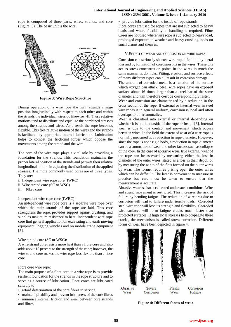
rope is composed of three parts: wires, strands, and core
(Figure. 3). The basic unit is the wire.
Figure 3: Wire Rope Structure
During operation of a wire rope the main strands change
position longitudinally with respect to each other and within
the strands the individual wires do likewise [4]. These relative
motions tend to distribute and equalize the combined stresses
among the strands and wires. As a result the rope becomes
flexible. This free relative motion of the wires and the strands
is facilitated by appropriate internal lubrication. Lubrication
helps to combat the frictional forces which oppose the
movements among the strand and the wire.
The core of the wire rope plays a vital role by providing a
foundation for the strands. This foundation maintains the
proper lateral position of the strands and permits their relative
longitudinal motion in adjusting the distribution of the applied
stresses. The more commonly used cores are of three types.
They are:
i. Independent wire rope core (IWRC)
ii. Wire strand core (SC or WSC)
iii. Fibre core
Independent wire rope core (IWRC):
An independent wire rope core is a separate wire rope over
which the main strands of the rope are laid. This core
strengthens the rope, provides support against crushing, and
supplies maximum resistance to heat. Independent wire rope
core find general application on excavating and earth moving
equipment, logging winches and on mobile crane equipment
[5].
Wire strand core (SC or WSC):
A wire strand core resists more heat than a fibre core and also
adds about 15 percent to the strength of the rope; however, the
wire strand core makes the wire rope less flexible than a fibre
core.
Fibre core wire rope:
The main purpose of a fibre core in a wire rope is to provide
resilient foundation for the strands in the rope structure and to
serve as a source of lubrication. Fibre cores are lubricated
suitably to
• retard deterioration of the core fibres in service
• maintain pliability and prevent brittleness of the core fibres
• minimise internal friction and wear between core strands
and fibres
• provide lubrication for the inside of rope strands
Fibre cores are used for ropes that are not subjected to heavy
loads and where flexibility in handling is required. Fibre
Cores are not used where wire rope is subjected to heavy load,
prolonged exposure to weather and heavy crushing loads on
small drums and sheaves.
V. EFFECT OF WEAR AND CORROSION ON WIRE ROPES:
Corrosion can seriously shorten wire rope life, both by metal
loss and by formation of corrosion pits in the wires. These pits
act as stress-concentration points in the wires in much the
same manner as do nicks. Pitting, erosion, and surface effects
of many different types can all result in corrosion damage.
The amount of corroded metal is a function of the surface
which oxygen can attack. Steel wire ropes have an exposed
surface about 16 times larger than a steel bar of the same
diameter and will therefore corrode correspondingly faster.
Wear and corrosion are characterized by a reduction in the
cross section of the rope. If external or internal wear in steel
wire ropes is in general uniform, corrosion is local and often
overlaps to other anomalies.
Wear is classified into external or internal depending on
whether it is on the outside of the rope or inside [6]. Internal
wear is due to the contact and movement which occurs
between wires. In the field the extent of wear of a wire rope is
normally measured as a reduction in rope diameter. However,
since the rope is not a rigid body, a reduction in rope diameter
can be a summation of wear and other factors such as collapse
of the core. In the case of abrasive wear, true external wear of
the rope can be assessed by measuring either the loss in
diameter of the outer wires, stated as a loss in their depth, or
by measuring the width of the flats formed on the outer wires
by wear. The former requires prising open the outer wires
which can be difficult. The later is convenient to measure in
practice but care must be taken to ensure that the
measurement is accurate.
Abrasive wear is also accelerated under such conditions. Wire
and strand movement is restricted. This increases the risk of
failure by bending fatigue. The reduction of wire area due to
corrosion will lead to failure under tensile loads. Corroded
steel wire rope will lose its strength and flexibility. Corroded
wire surfaces will form fatigue cracks much faster than
protected surfaces. If high local stresses help propagate these
cracks, the mechanism is called stress corrosion. Different
forms of wear have been depicted in figure 4.
Figure 4: Different forms of wear

Corrosion and its effect on wire rope used in underground coal mines
86 www.ijeas.org
The amount of corrosion can be reduced by reducing the
exposed surface. This can be done by galvanizing the rope
wires. A steel core can also be protected by a plastic coating.
An internal and external lubrication will also reduce or
prevent corrosion. Steel expands when it corrodes. Therefore,
sometimes an increase in rope diameter over time might be an
indication that the rope is corroding internally. Static ropes
(suspension ropes or rope sections lying over a saddle or an
equalizer sheave) are more likely to corrode faster than
running ropes/ winding ropes. This has been illustrated with
failure analysis of two different types of wire ropes one guide
rope which is static in nature and one winding rope which is a
moving rope.
VI. CASE STUDY – I:
Failure analysis of a guide rope used in coal mines:
A. Sample Description:
Failed samples from 10/12 pits of KB Colliery have been
received. The guide rope samples of 32mm diameter and six
over one (6/1) construction have come for investigating the
causes of failures. Three samples of failed guide rope of were
taken from three different position of the guide rope [7].
1. One broken guide rope sample
2. One guide rope sample from top side broken portion
3. One guide rope sample from bottom side of the
broken portioin
The photoes of the samples are given in Figure 5.
Figure 5: Broken guide rope sample
The following examinations were carried out to assess the
exact causes of failure of supplied guide rope.
B. Visual Examination:
Visual examination revealed that the top end and bottom end
portions of the failed guide rope was physically in good
condition while in the broken failed portion out of seven
wires, one wire have been broken out (Figure 5 & 6). After
cleaning, the broken portion of the guide rope was found to
have heavy wear and pittings (Figure 7).
Figure 6: After cleaning of failure broken end
Figure-7: Wear, corrosion & pittings in one wire
C. Examination of wear & corrosion:
1) Broken end of the guide rope:
The un-galvanized round steel guide rope wire sample on
physical examination revealed abrasive wear, helical
indentation marks, nicking and severe corrosion pittings on
the surface of the wire.
Max. Percentage reduction in diameter: 57.44%
Top end of the broken guide rope:
The un-galvanized round steel guide rope wire sample on
physical examination revealed abrasive wear, helical
indentation marks and corrosion pittings on the surface of the
wire.
Max. Percentage reduction in diameter: 6.2%
2) Bottom end of the broken guide rope:
The un-galvanized round steel guide rope wire sample on
physical examination revealed abrasive wear, helical
indentation marks and corrosion pittings on the surface of the
wire.
Max. Percentage reduction in diameter: 7.0%
D. Lubrication content in failed guide rope:
1) Broken end:
The lubrication condition of the given broken sample has
been examined and calculated on the basis of rope mass as per
IS: 3623-1978 and found below its critical passing value.
Top end & bottom end of the broken guide rope:
The lubrication condition of the given top end & bottom end
sample was examined and found satisfactory.
E. Micro-examination:
1) Broken end of the guide rope:
The failed broken sample after cutting, grinding and polishing
was examined under the microscope in an un-etched
condition. The sample revealed no harmful inclusion as per
IS: 4163-1982.
After etching in 2% nital solution the transverse and
longitudinal section of the guide rope wire revealed
normalized structure in a matrix of ferrite grains with
Failure broken end
Top end Bottom end
International Journal of Engineering and Applied Sciences (IJEAS)
ISSN: 2394-3661, Volume-3, Issue-1, January 2016
87 www.ijeas.org
intermittent fine pearlite in the grain boundary (Figure 8a)
typical to normalized low carbon steel. The structure of the
failed broken end sample revealed elongated grains (Figure
8b) and corrosion pittings (Figure 8c) in the longitudinal
section of the wire surface.
Visual Magnification 400X & 100X;
Micro photograph 2X180 Magnification
Figure 8a: Normalized structure 400X
Figure 8b: Elongated grains 400X
Figure 8c: Corrosion pittings in longitudinal section
100X
Top end:
The top end of the sample after cutting, grinding and
polishing was examined under the microscope in an un-etched
condition. The sample revealed no harmful inclusion as per
IS: 4163-1982.
After etching in 2% nital solution the sample revealed
normalized structure with uniform distribution of fine pearlite
in ferrite matrix (Figure. 9a) and corrosion pittings along the
grain (Figure 9b,9c,9d) of low carbon steel on the surface of
the wire both in transverse section and longitudinal section.
Figure 9a: Normalized structure 400X
Figure 9b: Corrosion pittings 400X
Figure 9c: Corrosion pittings 400X
Figure 9d: Corrosion pittings 400X
Bottom end:
The bottom end sample after cutting, grinding and polishing
was examined under the microscope in an un-etched
condition. The sample revealed no harmful inclusion as per
IS: 4163-1982.
After etching in 2% nital solution the sample revealed same
normalized structure of low carbon steel with fine pearlite in
the grain boundary in a ferrite matrix (Figure 10a) in both
transverse and longitudinal section. The grains are elongated
in all along the surface of the wire in longitudinal section
(Figure 10b).
Visual Magnification 400X , Micro Photograph 2X180
Magnification.

Corrosion and its effect on wire rope used in underground coal mines
88 www.ijeas.org
Figure 10a: Normalize structure 400X
Figure 10b: Elongated grains 400X
F. Chemical analysis:
Table II: Chemical analysis of the guide rope
G. Results & Conclusion:
1. From physical appearance of the fracture end which is a
family of cup & cone shaped structure indicative of
tensile failure.
2. Due to high reduction in diameter (57.44%) taken from
all single broken wires, may have caused failure by
tensile load causing fracture which exceeded the
breaking load.
3. Further the micro-examination of the fracture end and
bottom end revealed normalized structure with
elongated grain indicative of stress on the wires of the
rope.
Poor lubrication at the broken end of the guide rope
may leads to intermittent friction of wires forming nicks
prone to corrosion of the wires.
4. The chemical (carbon content) composition was below
the standard requirement.
VII. CASE STUDY – II:
Failure analysis of a winding rope used in coal mines:
A. Sample Description:
The failed sample of 25mm diameter and 6x7(6/1)
construction FMC wire ropes from Dobari Colliery of 2 pit
south side have been received to evaluate the causes of
failure. Sample in two pieces were taken to investigate the
cause of failure [8].
1. Fracture end
2. Fresh end
The Photographs of the samples are as under.
Figure 7: upper one – Fresh piece, Lower one - Broken
end
Figure 8: Fracture Rope Samples showing broken
surfaces
Figure 9: Fresh piece of rope
From the above figures it is clear that fibre core of the rope
has come-out of the fracture end. The fracture end of the rope
was badly damaged. The causes of the failure can be detailed
out from the following Metallurgical examination.
B. Macro examination/ Visual examination:
A. Strand 1:
One wire of the strand has also been broken from the middle
apart from the normal fracture of all the seven wires. The lay
length was 172mm (Figure 10)
Element % of
Element REMARKS
Carbon 0.16 As per IS: 1835-1976 for
round steel wire for rope, the
% of element should be as
under :
Carbon : 0.35 to 1.0
Manganese: 0.30 to 0.90
Silicon: 0.10 to 0.30
Sulphur & Phosphorus
acceptable within point
range P+S= 0.08, Max.
Manganese 0.48
Silicon 0.106
Sulphur 0.018
Phosphorus 0.023
International Journal of Engineering and Applied Sciences (IJEAS)
ISSN: 2394-3661, Volume-3, Issue-1, January 2016
89 www.ijeas.org
Figure 10: Broken wire of strand 1
Types of fractures are: two wires of conical tensile failure and
five wires of Corrosion fatigue failure (Figure 10a).
Figure 10a: Types of fracture of strand 1
Strand 2:
This strand was elongated and becomes straight having
longest lay length among all of 220mm. The nature of
fractures comprises of out of 7 wires, 5 wire of conical tensile
failure and 2 wires of corrosion fatigue failure (Figure 10b).
Figure 10b: Types of fracture of strand 2
Strand 3:
Two wires shows old fracture below its fracture end. The lay
length of the strand was 180mm. The natures of fracture
revealed out of 7 wires, 5 wires of corrosion fatigue failure
and 2 wires of crystalline failure on full section wire (Figure
10C).
Figure 10C: Types of fracture of strand 3
Strand 4:
This strand shows 5 old fractures out of 7 wires below its
fracture end. The lay length of the strand was 180mm. The
natures of fractures are: 2 wire of conical tensile failure and 5
wire of corrosion fatigue failure (Figure 10d).
Figure 10d: Types of fracture of strand 4
Strand 5:
This strand revealed 1 wire has crack near the fracture end out
of 7 wires. The lay length of the strand was 185mm. The
Nature of fractures are, 2 wire of conical tensile failure, 2
wires of crystalline failure on full section of wire and 3 wire of
corrosion fatigue failure Figure 10(e-I), Figure 10(e-II) &
Figure 10(e-III).
Figure 10(e-I): Types of fracture of strand 5
Figure 10 (e-II): Types of fracture of Strand 5 with one
wire broken from the middle
Figure 10(e-III): Types of fracture of Strand 5
Strand 6:

Corrosion and its effect on wire rope used in underground coal mines
90 www.ijeas.org
This strand shows tensile bending. The lay length of the strand
was 173mm. The natures of fractures are: 1 wire of
martensitic failure with fatigue crack developed and 6 wires
of fatigue failure (Figure 11).
Figure 11: Types of fracture of strand 6
Nature of fracture of transverse section in broken ends:
(Figure 11a)
Figure 11a: Types of fracture of strand 6
The above Figures indicate the Conical tensile and fatigue
failure fracture of the rope and no. 2 Strand showed elongated
i.e. lay length revealing the action of the heavy load on the
particular strand.
C. Examination of wear & corrosion:
1) Broken rope:
The galvanized round steel rope wire sample on physical
examination revealed abrasive wear, helical indentation
marks, nicks and corrosion pittings on the surface of the wire.
Percentage reduction in diameter: 10.48%
2) Fresh rope:
The galvanized round steel rope wire sample on physical
examination revealed abrasive wear, helical indentation
marks and corrosion pittings on the surface of the wire.
Percentage reduction in diameter: 7.11%
D. Lubrication content in FMC wire rope:
3) Broken end:
Retention of lubricant in fibre Main core
Percentage retention of lubricant in FMC = 6.43 %.
The lubrication condition of the wire rope has been examined
as per IS: 6594-1977. The Lubrication condition was very
poor and found dry also.
4) Fresh rope:
Retention of lubricant in fibre Main core
Percentage retention of lubricant in FMC = 9.17 %.
The lubrication condition of the wire rope has been examined
as per IS: 6594-1977. The Lubrication condition does not
confirm to IS: 6594-1977.
E. Micro-examination:
5) Broken end:
The broken sample after cutting, grinding and polishing was
examined under the microscope in an un-etched condition.
The sample revealed no harmful inclusion as per IS:
4163-1982.
After etching in 1% nital solution the transverse section
revealed uniform distribution of sorbitic pearlitic structure
Figure 12a and the longitudinal section revealed good cold
drawn structure Figure 12b of high carbon steel with
peripheral damage of zinc coating & corrosion pittings Figure
12c and Microstructure also reveals structural displacement
towards the tensile loading Figure 12d.
Figure 12a: Sorbitic - pearlitic structure in transverse
Section
Figure12b: Good cold drawn structure in longitudinal
section
Figure 12c: Corrosion pittings in longitudinal section
Figure 12d: Corrosion Pittings in longitudinal section

International Journal of Engineering and Applied Sciences (IJEAS)
ISSN: 2394-3661, Volume-3, Issue-1, January 2016
91 www.ijeas.org
F. Chemical analysis (in percentage):
Table III: Chemical analysis of the broken end of the
rope
Element % of
Element REMARKS
Carbon 0.799
As per IS: 1835-1976 for round steel
wire for rope, the % of element should
be as under :
Manganese 0.67 Carbon : 0.35 to 1.0
Silicon 0.186 Manganese: 0.30 to 0.90
Sulphur 0.028 Silicon: 0.10 to 0.30
Phosphorus 0.032 Sulphur & Phosphorus acceptable
within point range P+S= 0.08, Max.
G. Analysis of the result and conclusion:
1. From physical appearance of the fracture end, it seems
that the failure was primarily from tensile bending
stress.
2. Percentage reduction in wires diameter of broken ends
was found to be 10.48%.
3. Percentage absorption of lubrication in the broken
sample was found to be 6.43 %.
4. Chemical analysis of the broken sample was
confirming to the standards IS 1863-1976.
5. Micro-examination revealed a good cold drawn
structure except little corrosion pitting of the steel
wire rope. The grain distortion due to tensile
bending failure has also been absorbed.
It appears from the analyses result that the load on the rope
exceeded from the normal breaking strength of the wire rope
during operation. One strand of the rope was fully elongated
during operation. Its poor lubrication in the wire rope
aggravated the failure. However the rope was in good
condition and the breaking load was also within the range of
the rope. It seems sudden impact load was imparted on the
rope exceeding the breaking load of rope caused failure.
VIII. CONCLUSION:
Corrosion is a natural phenomenon which deteriorates the
industrial establishment and has a negative impact on
economic growth of any developed or developing country.
Further it poses a serious safety threat due to sudden failure of
industrial appliances. From the above two case studies it is
found that the static guide rope used in coal mines has been
failed due to excessive corrosion resulted in high reduction in
diameter (57.44%) leds to fracture due to tensile load. The
poor lubrication at the broken end of the guide rope leads to
intermittent friction of wires forming nicks prone to corrosion
of the wires. Further, the chemical (carbon content)
composition was below the standard requirement. On the
other hand the moving winding rope, the failure was primarily
from tensile bending stress. Micro-examination revealed a
good cold drawn structure except little corrosion pitting of the
steel wire rope. Its poor lubrication condition along with
sudden impact load in the wire rope caused the failure.
It can also inferred that static ropes (suspension ropes or rope
sections lying over a saddle or an equalizer sheave) are more
likely to corrode faster than running ropes/ winding ropes.
ACKNOWLEDGMENTS:
The authors are grateful to Director, CSIR-CIMFR, Dhanbad,
INDIA for his kind permission to publish the paper. The
views expressed in the paper are of the authors’ and not of the
organizations they serve.
REFERENCE:
[1] ASM International.Corrosion: Understanding the Basics (#06691G),
2000
[2] Behrens. Br. Corrosion Journal, Vol. 10, Issue 3, p 122, 1967.
[3] Bineet Kumar Singh, Munmun Basak, Martin West, Indranil Guha;
―Estimating the Cost of Corrosion in Indian industry‖,
Petrotech-2010.
[4] Jaynil Gunarkar, ―Wire rope, Chapter-5‖, Feb 06, 2013.
[5] Australian wire rope works Pty. Ltd.
[6] R. P. Singh, Mousumi Mallick, M. K. Verma & B. Ravi Kumar,
―Studies on metallurgical properties of wire rope for safe operation in
mines‖ Journal of Mines, Metals & Fuels, VOl.59, No.8,PP224-29,
August 2011.
[7] CIMFR report ―Study and failure analysis of 32mm diameter guide
rope of K.B. 10/12 pits colliery, B.C.C.L, Dhanbad, Jharkhand‖
October 15.
[8] CIMFR report ―Study the causes of failure of 25mm diameter winding
rope used for winding at Dobari Colliery, Bastacolla area, B.C.C.L.,
Dhanbad‖ October 15
Dr. R. P. Singh is Senior Principal Scientist and Head, Mine
Fire Model Gallery & Metallurgy Division at CSIR-Central Institute of
Mining and Fuel Research (CIMFR), Barwa Road, Dhanbad and Professor
in AcSIR. He did his Ph. D in Chemistry in 1989. He has been working in the
field of control of mine fire, ventilation investigation& planning and
metallographic studies on various mine appliances since last 25 years. He
has completed several S&T projects funded by Ministry of Coal, Govt. of
India in the field of mine fire and explosions. He has completed as a project
leader one of the prestigious project i.e. Mine Fire model Gallery at CIMFR
campus. He also worked with prestigious institute like NPCIL, L & T etc. in
joint collaboration projects. He has evolved HPHC fire suppression
technology which is very frequently used in underground coal mines to
control fire. He has published more than 50 technical papers in international
and national journals and international and national conference proceedings.
He executive member of AIMPS.
Mrs. Mousumi Mallick has done her B.E. in Metallurgical
Engineering from National Institute of Technology in 2004 and M.B.A
degree in Finance from ICFAI in 2007. She is a Scientist at CSIR-Central
Institute of Mining and Fuel Research (CIMFR), Barwa Road, Dhanbad.
Before joining to CSIR-CIMFR, Dhanbad she has worked with Ernst &
Young, Bangalore as a Tax Analyst and joined CSIR-NCL, Pune on 2008 as
a Jr. Scientist for one year and eight months in technology
commercialization of its in-house technology, establishing a technology
business incubator etc. At CSIR-CIMFR, she works on metallurgical
property evaluation and failure analysis of mining equipment used in
underground mining. She is an associate member of ―Institute of Engineers‖.
Mr. M. K. Verma has got Diploma in Metallurgical
Engineering from Government Poltechnique College, Dhanbad in 2000. He
has an experience of working with small scale industries for two years in the
area metal forming process. Since 2002 he is working with CSIR-CIMFR
and working in metallurgical properties of mining appliances, failure
analysis etc