corrosion in water boiler systems - marvin silbert and ... · steam drum deaerator storage tank to...
TRANSCRIPT

BoilerFeed Pump
Economizer Superheater
Turbine
Condenser
Makeup
Deaerator
FlashTank
SteamDrum
DeaeratorStorage
Tank
To HeatRecoverySystem
MudDrum
CoolingWater
CondensateExtraction Pump
Hotwell
BlowdownHotwell
Return to
Extraction Steam
CondensatePolisher
FeedwaterHeater
Fossil-Fired Boiler
Flow-AcceleratedFlow-AcceleratedCorrosion in Water Corrosion in Water
SystemsSystemsbyby
Marvin D. SilbertMarvin D. SilbertMarvin Silbert and AssociatesMarvin Silbert and Associates
This talk started as a presentation to the Niagara Frontier NACE conference in Buffalo. I needed a witty beginning and found that my humour about Buffalo tied so well into the topic that would like to use it again. It may also give you a snippet of information that you will retain from this talk and be able to use on your friends..
Having lived many years, just a stone's throw from Buffalo (and that's what we often did), I always made an assumption about Buffalo that was totally wrong. When we first got a TV set in our house, I saw it in the station ID. I saw it in newspapers brought in from Buffalo. I saw it in the team logos from the Sabres and the Bills.
Photo by: Frank PrazakCourtesy of Sabres Legends
It has even infiltrated to that most Canadian of institutions the donut shop. Look the the logo on Tim's sweater: crossed sabres and a buffalo.
Oh give me a home, where the buffalo roamWhere the deer and the antelope play,Where seldom is heard, a discouraging wordAnd the skies are not cloudy all day.
Home, home on the Range;Where the deer and the antelope play;Where seldom is heard, a discouraging word,And the skies are not cloudy all day.
There's a famous cowboy song that says something about where you might find a buffalo. Unless it's in a zoo, I doubt that you will find one within a couple thousand kilometres of Buffalo. Until I started preparing this talk, I always assumed that the city of Buffalo was named after those bovine behemoths.

There were no Buffalos in Buffalo.The name comes from the French:
Beau FleuveBeautiful River
As I started looking into the early history of the Niagara area, it suddenly hit me that this teritory was once claimed as part of New France and the early explorers spoke French. The name is derived from beau fleuve, literally beautiful river with a fleuve being a big river.
from Forty-Second Street (1933)Lyrics: Al Dubin, Music: Harry Warren
Beau Fleuve -O
Buffalo
I'll go home and get my panties,You go home and get your scanties,And away we'll go;Mm, off we're gonna shuffle,Shuffle off to Beau Fleuve
That's better!Let's go for it!
Over the years, the spelling changed and an "o" got tacked onto the end. There are numerous theories about how that happened and probably none of them are true. I would expect it just made for better rhymes as in the famous Shuffle off to Buffalo song from the 30s.
A few km downriver there is a large waterfall. Is that the same waterfall the early explorers found. Yes and no. They found a large waterfall, but it was further down river and did not have that horseshoe shape. That change was the result of the massive erosive forces exerted by the fast flowing stream which prior to the 1950s carried the full 5000 m3 s-1 flow and moved the waterfall south at about a metre per year. If the Niagara River can wear away the underlining rock to such an extent, what sort of impact can we expect on the walls as water flows within a metal pipe?

MainfromCity
Basement
1st
Floor
HotWaterHeater
2nd
Floor
Household Hot Water Distribution System
In most water systems for process, cooling or boiler applications, the water is flowing and it can sometimes be moving at a good clip. Think about a fairly simple example of a flowing system, the supply of hot water. In a house, it's very simple with copper lines running from the hot water tank to the various taps on demand. It may take a bit longer to get to the second flor, but we accept that and live woth it. Domestic hot water is not deoxygenated and it will quickly form an oxide layer that will cover the surface and protect the copper from further oxidation.
MainfromCity
Basement
12th
Floor
HotWaterHeater
WestWing
24th
Floor
Hot Water Distribution System for Major Buildings
CirculatingHot Water
Loop
The system becomes much more complex in a large building, e.g., an office tower, hotel, school or apartment building. People using a washroom or kitchen expect to see hot water appear when they open the tap regardless of where they are in the building. To accomplish this goal, the hot water circulates in a continuous loop. Individual washrooms or kitchens take their hot water from the loop. If the flow velocity is set too high, this oxide is not all that adherent and it may be removed. Where it's removed, the water will contact bare metal which will immediately react with the dissolved oxygen to form a new oxide layer ...
Section of 1" Riser from Recirculating Hot-Water System Showing Extensive
Flow-Accelerated Corrosion
… which will of course be removed. In time serious thinning occurs and leaks start to develop. The ideal flow should be less than 50-60 cm/s. This cross section of copper tubing was cut from a recirculating hot-water system in a large apartment building just downstream of a right-angle bend. The building experienced major water damage when the tubing started to fail. This tubing was replaced after having been in service for five years. The solution was quite simple. Installing a recirculating line around the pump reduced the flow velocity.

FLOW
1Start with water
at surface of base metal
SIMPLIFIED MECHANISM OF SIMPLIFIED MECHANISM OF FLOW-ACCELERATED CORROSION FLOW-ACCELERATED CORROSION
Depending upon what you read or who you're talking to, this corrosion process may go under various names: Erosion-Corrosion, Flow-Accelerated Corrosion, Flow- Assisted Corrosion or simply FAC. It can be the result of several causes including low pH, poor dissolved oxygen control, overfeed of chelants or the use of inappropriate dispersants. No matter which cause or combination of causes is responsible, the general mechanism goes essentially as follows:
1) The inside surface of the pipe comes in contact with the solution.
FLOW
2.Reaction between dissolved oxygen and metal surface forms a protective
oxide layer
1Start with water
at surface of base metal
SIMPLIFIED MECHANISM OF SIMPLIFIED MECHANISM OF FLOW-ACCELERATED CORROSION FLOW-ACCELERATED CORROSION
2) The surface is attacked (or treated) to form a protective metal surface.
SIMPLIFIED MECHANISM OF SIMPLIFIED MECHANISM OF FLOW-ACCELERATED CORROSION FLOW-ACCELERATED CORROSION
FLOW
2.Reaction between dissolved oxygen and metal surface forms a protective
oxide layer
3.High flow velocity will remove some oxide and carry it
with flow.
1Start with water
at surface of base metal
3) As a result of a flow velocity, some of that surface is either eroded away or dissolved and carried with the flow, likely to deposit elsewhere downstream in the system.

SIMPLIFIED MECHANISM OF SIMPLIFIED MECHANISM OF FLOW-ACCELERATED CORROSION FLOW-ACCELERATED CORROSION
FLOW
2.Reaction between dissolved oxygen and metal surface forms a protective
oxide layer
3.High flow velocity will remove some oxide and carry it
with flow.
4.New oxide layer forms on bare
metal
1Start with water
at surface of base metal
4) As conditions favour the formation of the protective surface, a new layer will be formed wherever bare metal is exposed.
SIMPLIFIED MECHANISM OF SIMPLIFIED MECHANISM OF FLOW-ACCELERATED CORROSION FLOW-ACCELERATED CORROSION
FLOW
2.Reaction between dissolved oxygen and metal surface forms a protective
oxide layer
3.High flow velocity will remove some oxide and carry it
with flow.
5.Process will
continue until wall thinning results in
failure
4.New oxide layer forms on bare
metal
1Start with water
at surface of base metal
5) In time, the continual formation and removal process can reduce the wall thickness to the point that it is no longer safe to operate the system.
Directionof Flow
ErodedSurface
Wall Thinning Resulting fromWall Thinning Resulting fromFlow-Accelerated Corrosion Flow-Accelerated Corrosion
New System After Extended Operation
FAC will be most common in locations where there is a change of direction, e.g. pipe elbows.

Photos of FAC in Copper PipingPhotos of FAC in Copper Piping
Sand Sand DuneDune
CometComet
HorseshoeHorseshoe
From Herro and Port, The NALCO Guide to Cooling Water Systems Failure Analysis
If you have the appropriate equipment, FAC can also lead to the production of some rather spectacular photographs.
1
2
3
4
100
Temperature (°C)110 120 130 140 150 160 170
Loss
Rat
e (m
m/y
ear)
983Flow (kg/hr)
907
756
605
491
378
227
Flow-and-Temperature Dependence ofSingle-Phase Flow-Accelerated Corrosion
pH controlled at 9.04(25°C) with ammonia
302
While the flowrates in the figure may refer to a specific system, it follows that FAC is dependent upon velocity. If there is no flow, the surface protection holds and there is no FAC. If it flows, there is FAC and the extent of the damage would be aggravated if changes are made that would increase the flow, e.g., if a leak develops in a heat exchanger, the quickest way to get a system back on line is to find the leaking tubes and plug them. While the design may have the capacity to operate with a number of plugged tubes, each tube that is lost requires that the velocity must increase through the remaining tubes in order to maintain the required steam flow.
Leak
Consequences of FACErodedSurface
Small leaks of low-pressure fluids may damageequipment or surroundings
Major leaks of high-pressure or toxic fluids mayresult in injury or death
Inevitably it's going to let go.
FAC can wreak havoc on a major system that operates at high temperatures and pressures as in electrical generation or with dangerous or corrosive materials such as H2S. That copper pipe failure did tens of thousands of dollars of damage to walls and decorations. At the Surry nuclear plant in Virginia, NDT had shown substantial metal loss on an elbow at the discharge of the boiler feed pump. It was to be replaced during the next outage, but let go while a crew was erecting the scaffolding. The pressure was 800+ psi and the water flashed to steam, killing a few people and severely injuring several others.

BOILER CYCLE FOR AN ELECTRICAL GENERATING STATION
BoilerFeed Pump
Economizer Superheater
HP Turbine
Makeup
DeaeratorSteamDrum
DeaeratorStorage
TankMudDrum
CoolingWater
CondensateExtraction
Pump
Hotwell
Blowdown
ExtractionSteam
CondensatePolisher
LPFeedwater
Heaters
HPFeedwater
Heaters
toDeaerator
toCondenser
viaDrains Cooler
fromExtraction
Steam
fromExtraction
Steam
LP Turbine
MoistureSeparator
Reheator
Drains to Last HP
Feedheater Shell
Condenser
ExtractionSteam
As my first example, let's look at a major HP boiler system. It is designed in a loop to conserve water and energy. The condensed steam is recovered and fed back through the system. This water is relatively cold compared to that in the boiler. To minimize any thermal shock to the system, this water is heated in a series of small steps using a series of feedwater heaters. A typical HP generating station may have 3 LP heaters, a deaerating heater and 2 HP heaters.
The heart of the system is the boiler. It can be heated by gas, oil, coal, garbage or another fluid such as heavy water in the CANDU or waste heat from an industrial plant. With their size and the fact that they pass through floors and walls are built around them, it can be almost impossible to photograph a boiler. I was lucky to be a Pickering "B" one day during construction and got this one and coupled it with a few photos from B&W. The main construction material for most boilers is carbon steel. The tubes in a fossil boiler are usually carbon steel. In a nuclear, they tend to be exotic high Ni alloys.
Tube-and-Shell Heat ExchangerSingle Pass vs. Double Pass Designs with Water FlowingThrough the Tubes and Process Fluid through Shell-Side
OutletWaterbox
Double Pass
OutletWaterbox
Single Pass
InletWaterbox
Tubesheet
ProcessFluidInlet
ProcessFluidOutletInlet
Waterbox
The feedwater heaters are heat exchangers that cascade extraction steam or recovered hot water down the shell side to heat the feedwater as it goes up the tube side. The shell iscarbon steel and the tubes can be carbon steel, brass, copper or stainless. Traditionally, the choice of material was made to minimize cost and maximize heat transfer. Whether you understand the operation of major steam systems or this is your first exposure to them, I'm sure you can see that it's not a good idea to put Cu and Fe together in a water system. You will have a copper alloy cathode and an iron anode and that anode is inevitably going into solution.

The upper photo shows a Pickering feedwater heater. To get the capacity, two are used in parallel.
The bottom shows a pair feedwater heaters in Gentilly, disaasembled for maintenance and showing the tube structure.
Deaerating Heater
Storage Tank
Condensate Inlet
Steam Inlet
Deaerated Water Outlet
ChemicalAddition
Vent
Feed to Boiler
Sprays
from www.cochrane.comCochrane Deaerator
The fourth feedwater heater is designed to act as a deaerator. The heated liquid is sprayed in and meets a rising flow of steam. This brings the water to 110-115°C. that strips away the dissolved gases and vents them to atmosphere. You will se aplume about 1-1.5 m rising from the roof. This gets rid of the bulk of the dissolved oxygen. Coupling this with a high pH provides the reducing conditions needed to form the protective oxide magnetite (Fe3O4). One might describe the system as a thin layer of magnetite supported by a steel structure.
The upper photograph shows the turbine generating system at Boundary Dam near Estavan Saskatechewan. The condenser is located below the turbine.
The lower photograph shows the turbine at Lakeview in Mississauga disassembled for maintenance. You can see the double sets of blading. The steam enters at the centre and exits at the ends.

This turbine generator set is at the Bruce "A" station. This a big system spinning at 3600 rpm. Going from L to R you have the HP turbine, three sets of tandem LP turbines and the generator at the far end. The round vessels sticking through the floor between the HP and LP are the moisture separators.
To get a feel for the size, look at the chem tech on his lab transporter by one of the shutdown valves. I purchased that transporter after being bugged by the chem techs. It was easy to justify it as it saved more than a million dollars over the 30-year economic lifetime of the station, just be reducing walking time to get samples. The turbine hall is half a km long.
This is the chemical addition station for two units.
1) The oxygen scavenger is added to the dearator storage tank to finish the job of oxygen removal.
2) An volatile amine such as ammonia or morpholine is added at the discharge of the condensate extraction pump to protect the entire feedwater train.
3) Some plants also use solid materials, such as trisodium phosphate. This is added directly to the steam drum.
6Fe2O3 + N2H4
6CuO + N2H4
4Fe3O4 + 2H2O + N2
4Cu2O + 2H2O + N2
O2 + N2H4 2H2O + N2
3N2H4 3NH3 + N2
2N2H4 2NH3 + H2 + N2
200-320°C>320°C
HydrazineAs an oxygen scavenger
High-temperature decomposition
As a metal passivator
There are a number of chemical scavengers for oxygen removal with the most common being hydrazine. At high concentrations, it's potent stuff. Hydrazine and lox are the fuel for NASA's liquid-fuelled.

8 9 10 11 12 13-12
-11
-10
-9
-8
-7
-6
300°C250°C
200°C
150°C
100°C
50°C
Mol
/kg
of F
e(II)
pH at 25°C
Solubility of Magnetitevs. pH and Temperature
10
10
10
10
10
10
10
While magnetite has generally been considered as a stable and adherent protective coating that insoluble in high-pH water. In reality, it has a very small solubility that must be taken into account when choosing the pH at which the system operates, especially when it can be flowing in excess of 1000 kg/s.
Note that you don't measure pH at system temperature as doing so ranges from impractical to impossible. All samples are depressurized and cooled to 25°C.
Solubility of Copper in Ammoniated Water
5 6 7 8 9 10 11 12
10,000
Cop
per (
µg/k
g)
1,000
100
10
1
pH at 25°C
30°C
90°C
If copper alloys are present, the solubility of copper must also be considered when establishing the operating range. Cu is soluble both undr acidic and alkaline conditions.
8 9 10 11 12 13
-9
-8
-7
-6
300°C
250°C
200°C
150°C
Mol
/kg
of F
e(II)
pH at 25°C
AllFerrousSystems
Systemswith
Copper Solubility of Magnetitevs. pH and Temperature
100°C50°C
10
10
10
10
A pH range from 9.5-9.8 has been accepted as the best compromise to minimize the solubility of the magnetite and the transport of corrosion products for all ferrous systems. It is a compromise made to avoid moving magnetite from one temperature region to another. When copper alloys are present, the pH must be dropped to 8.8-9.2 to avoid dissolving copper, but this is unfortunately a poor compromise as it results in about an order of magnitude higher solubility for the magnetite than would occur in the higher pH region.

10
20
30
40
50
60
70
80
90
50 100 150 200 250 300 350Temperature (°C)
Mag
netit
e (µ
g/kg
)
8.6
pH
8.9
9.0
9.2
9.4
9.6
Solubility of Magnetite in Ammoniated Water
0.1
Ammonia(µg/kg)
0.2
0.3
0.4512
The curves we just looked at become very interesting when we take alice through them. We see a family of curves with the corrosion rate for each pH range peaking in the 150-200°C range.
10
20
30
40
50
60
50 100 150 200 250 300 350Temperature (°C)
Mag
netit
e (µ
g/kg
)
pH 9.5 - 9.8
Solubility of Magnetite in Ammoniated Water
pH 8.8 - 9.2
Con
dens
er
LPFe
edhe
ater
s
Dea
erat
or
HP
Feed
heat
ers
Boi
ler
When labelled in terms of the two pH ranges and the individual components, it can be seen that the corrosion rate peaks in the HP heaters. If you have copper in the system and carbon steel tubes in the HP heaters, the system is destined to fail. It's only in the last few years that operators and designers have accepted the importance of chemical control in the system and the need to stop using copper alloys. Many major generating stations have undergone life-extension refurbishments that have included retubing their condenser and feedwater heaters to remove copper from the system.
Reducing Chemistry for Reducing Chemistry for Steam GeneratorsSteam Generators
For systems containing Cu
pH: 8.8-9.2 with morpholine or ammoniaHydrazine: 10 µg/kg
For all-ferrous systems
pH: 9.2-9.4 with morpholineHydrazine: 10 µg/kg
pH: 9.5-9.8 with ammoniaHydrazine: 100-200 µg/kg
What's achievable? Less than 10 µg/L of circulating iron in a system with clean condensate returns.
Over the years the trend has gone from a small 10-20 µg/L excess of hydrazine to a high of 100-200µg/L. Nuclear generating stations operate in the 4-6 MPa range. Several use morpholine to keep the pH at 9.3-9.5 on all ferrous systems and keeping the hydrazine at the lower range. The German utilities, favour High AVT with the pH at 9.8 or higher with ammonia and more than 100 µg/L of hydrazine to exclude all traces of oxygen. There is evidence that a trace of O2 may provide a self-repair mechanism for the magnetite. There is also some limited evidence that plants using the higher hydrazine concentration tend to experience increased FAC.
Note that the 10µg/L target with a 1000 kg/s steam flow can amount to hundreds of kg/year.

2
4
6
8
100 200 300 400
Iron
(ppb
)
0.2 0.4
Oxygen, ppb µS/cm
Feedwater in a Supercritical Unitfor different oxygen concentrations and cation conductivities. (from EPRI data)
The latest trend has been a switch to oxidizing conditions as the best way to slow down the FAC. The gamma-iron oxide that forms is much more adherent than the magnetite formed under reducing conditions. This is now the standard guideline from EPRI for many of the newer combined cycle plants operate this way as do some of the higher pressure fossil-fired units. It is applicable only to those plants that can maintain the necessary water quality. We are talking large volumes of water produced and maintained with the same quality you would expect in high-quality lab water.
Two-Phase FlowTwo-Phase Flow
TurbineSteamInlet
SteamExhaust
SteamlineSteamCondensedWater Droplets
As the steam leaves the boiler and starts to do some work, it will also start to cool down and condensed droplets will start to form. This two-phase flow can occur in the moisture separator between the HP and LP turbines or somewhere down a long steamline run in a pulp & paper mill. Now the system is more complex as it is necessary to minimize FAC damage from the liquid drops that impinge on the walls and at the same time leave some protection with the steam that carries on through the system.
TEMPERATURE (°C)
Log Kd
2
1
0
-1
-2
-30 200100 300
AmmoniaCyclohexylamine
Quinuclidine
3-Methoxy-propylamine
1,2-Diamino-ethane
Morpholine
3-HydroxyquinuclidineAMP
(From data of Cobble and Turner, EPRI NP-4209)
100
10
1
0.1
0.01
0.001
Kd
RELATIVE VOLATILITIES OF AMINES
Steam Phase
Liquid Phase
In the 150-200°C range ammonia doesn't do a very good job for two reasons. It loses much of its strength advantage and it tends to go with the steam at the expense of the liquid. Morpholine distributes almost equally between the two phases and will protect both and has lead to its use in nuclear systems to protect the moisture separator between the HP and LP turbines.

0 200
TEMPERATURE (°C)
7.0
6.0
5.0
4.0
3.0
Ammonia
Morpholine
AMP
QuinuclidineCyclohexylamine
100 300
3-Hydroxyquinuclidine
RELATIVE BASE STRENGTHS OF AMINES(From data of Cobble and Turner, EPRI NP-4209)
1,2-Diamino-ethane3-Methoxy-
propylamine
pK b
Stro
nger
Wea
ker
Ammonia may have a pKb an order of magnitude lower than that of morpholine at 25°C, but this is a real system operating at higher temperatures. By 150°C that advantage is gone and both are of equal strength.
9.0 9.2 9.4 9.6
COMPARISON OF CORROSION RATES
pH @ ROOM TEMPERATURE
µm/hr
3.0
2.0
1.0
0
AMMONIA
MORPHOLINE
AMP
TEST CONDITIONS: TEMP 175 C, 10 % MOISTURE IN STEAM and FLOW RATE 50 m/s (COMPILED FROM EDF DATA)
Electricité de France data supports the preference of morpholine over ammonia to provide protection against FAC in two-phase flow regions. The data shows much lower corrosion rates with morpholine until very high pH levels are reached.
Higher-pressure fossil plants must use ammonia as their higher operating temperatures will thermally decompose most amines to ammonia plus a collection of organic fragments that includes a number of weak organic acids that can be corrosive to carbon steel.
CLASSES OF COOLING WATER SYSTEMS
CLOSED-RECIRCULATING
COOLINGWATER
HEAT EXCHANGER
ONCE-THROUGH
WARM WATER RETURN
HEAT LOAD
RIVER ORLAKE
OPEN-RECIRCULATING
LOSSES
MAKEUP
COOLINGTOWER
EVAPORATION
FAC plays an important role in cooling water treatment. Industrial cooling can fit into three classes:
1. Once-through from the lake or river through the process and back.
2. Open-recirculating save water by making use of evaporative cooling. The cooling tower will be visible.
3. Closed are generally used for the internal circuits. A car coling system is a closed system.
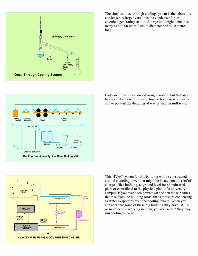
Laboratory Condenser
SewerTo
LaboratoryWater Tap
From
Once-Through Cooling System
The simplest once-through cooling system is the laboratory condenser. A larger version is the condenser for an electrical generating station. A large unit might contain as many as 50,000 tubes 2 cm in diameter and 5-10 metres long.
COOLINGTOWER
REHEATFURNACE
SCALEBREAKER ROLLS
RUNOUTTABLE
MILL FLUME
LAGOON / SCALE PIT
HOTWELL COLDWELL
FILTERS
Cooling Circuit in a Typical Steel Rolling Mill
Early steel mills used once-through cooling, but that idea has been abandoned for some time to both conserve water and to prevent the dumping of wastes such as mill scale.
FREONSYSTEM
COMPRESSOR
EXPANSIONVALVE
CONDENSER
COOLINGTOWER
EVAPORATOR
HVAC SYSTEM USING A COMPRESSION CHILLER
BUILDINGDISTRIBUTION
SYSTEM
GAS-FIREDHEATER
(SUMMER)CHILLEDWATER
(WINTER)HOT
WATER
This HVAC system for this building will be constructed around a cooling tower that might be located on the roof of a large office building, at ground level for an industrial plant or centralized to the physical plant of a university campus. If you ever been downtown and sen those plumes that rise from the building roofs, that's moisture condensing as water evaporates from the cooling towers. When you consider that some of these big building may have 10,000 or more people working in them, you realize that they may run cooling all year.

TUNDISHCONTAINING
MOLTENSTEEL
COOLINGTOWER
USE OF RECIRCULTING-COOLINGLOOP TO COOL COPPER MOULD
FOR A CONTINUOUS CASTINGMACHINE IN A STEEL MILL
PLATE-AND-FRAMEHEAT EXCHANGER
COPPERMOULD
CONTINUOUSBILLET
Molten steel enters mould
Must have solid skin as it exits mould
In critical applications as in this continuous casting machine where surface temperatures can be as high as 140°C, it is common to use a closed loop, which is then in turn cooled by the tower or once through water. Another example is the cooling system in your car.
CarbuncleActive corrosion under carbuncle
Microbiologically Induced Corrosion(MIC) in Heat Exchanger
Most process streams are cooled via heat exchangers. Give Mother Nature a chance and a bit of time and that heat exchanger will look like this. Look at those carbuncles.
Cross Section of an Active Tubercule
Water
Crust
Core
Fluid-Filled Cavity
Corroding FloorMetal Surface
Inner Shell
Fracturein Crust
Under them, there will be a series of oxidation proceses that would form a topic for a seminar by itself. If you are growing curbuncles, there are two things that will happen:
The pipe walls become rough and that requires additional pumping power.
You're eventually going to end up with a hole through the pipe.

Cross Section of a Protected Surface
Water
Metal Surface
Protected Surface
FAC plays an important role in cooling water treatment; butrarely discussed in this context and that is unfortunate as an understanding the role of FAC could help explain some of those situations where products appear to fail. Chromates were the best corrosion inhibitors you could find for a cooling system. Today, they are banned and the industry has switched to all-organic treatment programs. These protect carbon steel by laying down a protective film of calcium and phosphonate or phosphate, perhaps with a bit of iron in it. At the same time, the flowing water that passes across that film is trying to remove it.
Effectiveness of a Protected Surface
Water
Metal Surface
Protected Surface
Too thin!May not offer adequate
protection
Ideal!Provides cost-effective
protection
Too thick!Protection will not be
cost effective.
If a treatment program is going to succeed, a stable, uniformly thick and adherent film must cover the entire surface. Laboratory testing and field trials during the development of a particular product establish the ideal dosage for a number of standard applications. Whether or not it is said (and usually it isn't), the reason for that choice is the balance between formation of that protective film and its removal. If the dosage is set lower, the film may be removed and if it is set higher, the application cost goes too high and the product loses its competitiveness.
TIME
REL
ATI
VE C
ON
CEN
TRA
TIO
N
1
2
4
6 8
10
20
40
60 80
100
0
Rate of Formation for Protective Surface
Normaloperating
addition rate
High start-upaddition rate
Most water treatment programs recommend a start-up dosage that is double that for normal operation. I have never met anyone from a water-treatment company who could tell me why, but there is a very logical reason for doing so. It can take several weeks to build up a stable and adherent layer and until it is formed, the balance can quickly tip to let the flow damage or even remove the film. Doubling the dosage speeds the growth of the film to get to that balance.

CORROSION RATE vs. CONTROL
0
2
4
6
8
10
5 10 15 20 25 30
bars: CORROSION RATE (mpy)line: DAYS/MONTH BELOW SPEC
MONTHS
Once the film is formed, the product dosage must be tightly controlled. In one side-by-side comparison, plants "A" and "B" used the same treatment program. "A" had an automatic system. "B" was manually controlled and lack of attention would allow the dosage creep down until there was a panic and it was brought way up and allowed to drift again. In spite of the fact that both plants averaged the same total dosage over the year, corrosion rates were very low for "A" and quite high for "B". If the addition rates fluctuate, the film can be extensively damaged if the addition rate is too low for extended periods. It took extra time to develop that initial film when the program was introduced and a similar length of time will be needed to do a major rebuild as compared to performing a simple patch.
To Maintain a Stable Protective Film
Rate of Formation = Rate of RemovalControlled by:
Product Dosage
Influenced by:
Maximum flow Flow cycling Temperature fluctuations Start-up & Shutdown
This is normally set during product
development and carved in stone.
If there are so many influencers, the product dosage can not be
the same for all systems or even all sections of the same system.
When flowrates are particularly high, it may be necessary to boost the dosage ... and vice versa when they go low. Plant operators frequently complain that water-treatment companies always boost their dosage whenever they get into trouble and hint this just a route to boost revenue. Treatments based upon average conditions may fail if there are localized high flowrates and/or turbulence within the system.
FEEDWATER
STEAM
STEAMDRUM
OUTLETFEEDER
INLETFEEDER
INLETHEADER
INLETHEADER
FUEL CHANNEL
pH-and-Temperature Dependence of Single-Phase Flow-Accelerated Corrosion in CANDU System
310°CMAGNETITEDISSOLVES
265°CMAGNETITEDEPOSITS
STEAM GENERATOR
ALLOYS USED
FuelFuel Channel
Steam Generator
Feeders & Headers
ZircaloyZircaloy &Stainless SteelInconel 600 orIncoloy 800Carbon Steel
The primary heat-transport system of the CANDU system has developed severe wall thinning as a result of FAC. The fuel channel is constructed of Zircaloy with stainless steel end fittings. The feeders carry the heated water to the headers from which it is pumped through the steam generators and returned to complete the cycle. The flowrate in the feeders averages 20 m s-1. This is sufficient to remove the protective magnetite and carry it through the system.The fuel exiting the fuel channel enters the feeder at 310°C and returns from the steam generator at 265°C.

This photo shows the location of the feeders for Bruce "A". There are 480 fuel channels. The flow uses two loops, making alternate channels inlet and outlet.
10.0 / 10.59.0 / 9.5
9.5 / 10.0
9.8 / 10.2
7
6
5
4
3
250 260 270 280 290 300 310
Tota
l Iro
n (µ
g/kg
)
Temperature (°C)
pH-and-Temperature Dependence of Single-Phase Flow-Accelerated Corrosion in CANDU System
pH (pH in H20) / pHa (apparent pH in D20)
Inlet Header Outlet Header
The "pH" is controlled at 10.5. This is a heavy water system and a pH meter calibrated with standard buffers will read high. This would put the equivalent pH closer to 10.0. The magnetite solubility curves for that range, favour removing magnetite from the outlet headers and redepositing it downstream. Adjusting the pH range may appear to be an obvious solution, but it is not as there is a major concern about bringing deposits back into the fuel channel. Anything that sits on the fuel will impede heat transfer. It may also get activated by the intense neutron field and end up as a source of high radiation dosage to the workers.
Water
Product(600)
Depleted(120)
Feed(145)
k = 2.35 @ 30°C and 1.91 @ 130°C
H O + HDS HDO + H S2 2
Girdler Sulfide Process
HydrogenSulfide
@ 2 MPa
(320) (80)
ColdTower30°C
HotTower130°C
First-Stage Tower(ppm D)
The Girdler-Sulfide or GS process for heavy-water production is based upon a shift of equilibrium between the deuterium in water vs. that in H2S going from a hot tower at 130°C and a cold tower at 30°C. The bulk of the towers and pipework will be carbon steel. The H2S reacts with the iron to form an insoluble iron sulfide coating. If the flow velocity is too high, it will be wiped off and we're into an FAC problem. In some of the more-difficult regions, a stainless steel may be used to avoid the FAC damage, but in a plant of this type, it's just not practical to do so throughout the plant.

NH2C
C
CH2
O
OH
C
O
OH
NCH2
C
CH2
O
OH
CH2
C
O
OH
N
C
CH2
O
OH
C
O
O
NCH2
C
CH2
O
OH
CH2
C
O
OCa
EDTA Molecule Ca - EDTA Complex
H2C
H2C
H2C
NCH2C
O
OH
C
O
OHH2C
C
O
OHH2C
NTA Molecule Ca - NTA Complex
NCH2C
O
OH
C
O
OH2C
C
O
OH2C
Ca
Chelation of Calcium by EDTA and NTA
+ Ca2+
+ Ca2+
Chelants and a variety of complex organic molecules are often incorporated into various proprietary cooling water and boiler treatment formulations. The objective is to keep the system clean by dissolving minor calcium or iron deposits. The key word in that last sentence is minor. A boiler or a cooling system can be quite dynamic and there is a fine line between the conditions that promote clean-up and those that promote corrosion. Be aware that the two C words may be synonyms, especially if any oxygen gets into the system. Immediately you form an oxide and the chelant cleans it up ... until it fails.
Douglas Point Generating StationDouglas Point Generating Station
Switching between reducing conditions and oxidizing conditions can place a severe stress upon the system and causes the surface to break away. Repeated cycling between the two can result in wall thinning and eventual failure. With proper controls, this cycling can be utilized to cleaning or decontaminate system surfaces. The Douglas Point nuclear station used this technique to decontaminate the primary circuit. This circuit was normally reducing. O2 was added just prior to a weekend shutdown. Coupled with the rapid change of heat flux, this released large quantities of magnetite (which contained 60Co) from the boiler and piping surfaces. Several repeats over a year significantly reduced the radiation fields from the boiler and piping surfaces.
Minimum-ThicknessHole
Directionof Flow
Leak
ErodedSurface
Detection of Metal Loss with Minimum-Thickness Holes
New System After Extended Operation
There is a need for a quick and dirty method that can be applied in the field to detect the progress of FAC.
One of the simplest is the minimum-thickness hole made by drilling very small diameter hole to the depth of the minimum wall thickness that can be tolerated. I'm sure we all cringe with horror just thinking about using one in a steam line or in a process with toxic materials. I wouldn't have believed any serious use had I not seen them used at the USAEC D2O Savannah River plants to check for FeS-related FAC. The operators wave some Pb-acetate paper near the hole to see if it turns black.

MILLIPORE Filter System
Some iron will be soluble, but most tends to be insoluble and can be concentrated by filtering the solution through a very-fine pored membrane filter. The most-common supplier for the membranes has traditionally been Millipore; hence, the process is often referred to as Millipore filtration. While a variety of pore sizes have been used, the most commonly is 0.47 µm. The apparatus is extremely simple and consists of standard laboratory components. A simple hand pump is usually adequate. A 1.0 L sample is taken and filtered and the filter compared with the standards on the Babcock & Wilcox charts.
10 25 50 75
100 250 500 1000
SIMULATION OF BABCOCK & WILCOX MEMBRANE FILTER COMPARISON CHARTDensities represent concentration in µg/L for a 1.0 L sample filtered through a 0.45 µm membrane filter.
The colour gives the approximate proportion of hematite and magnetite in suspension.
The charts range from magnetite (black) to hematite (yellow). The intensity approximates the concentration and the colour the composition. In systems, with high solids, the filters plug and filtration time can be very high. For these, use smaller volumes and adjust the chart appropriately and vice versa for very clean systems.
There are also a variety of NDT (non-destructive testing) procedures such as ultrasonic and ECT (eddy-current testing) to measure wall thickness. Some can be used during operation. Checking heat exchanger tubes requires a plant outage with the system drained.
for more information, contact me:
Copies of the paper are on the website under Bibligraphy
Marvin Silbert and Associates23 Glenelia Avenue
Toronto, ON, Canada, M2M 2K6416-225-4541
Marvin Silbert
[email protected] http://www.silbert.org
If you want a copy of the text, it is posted on my website.