corrtran® mv corrosion monitoring...
TRANSCRIPT

MONITORING TRANSMITTER
PROCESS AUTOMATION
CorrTran® MV CORROSION


Subject to modifications www.pepperl-fuchs.us
USA: +1 330 486 0002 Singapore: +65 6779 9091
Copyright Pepperl+Fuchs
Germany: +49 621 776 2222
CorrTran MV Corrosion Monitor
1
Contents
1 SAFETY INSTRUCTIONS / DISCLAIMER ................................................................... 2
1.1 Designated use .................................................................................................... 2
1.2 Installation, commissioning, and operation .......................................................... 2
1.3 Operational safety ................................................................................................ 2
1.4 Maintenance safety ............................................................................................... 2
1.5 Notes on safety conventions and symbols ........................................................... 3
1.6 Disclaimer ............................................................................................................. 3
2 IDENTIFICATION ........................................................................................................... 3
2.1 Device designation ............................................................................................... 3
2.2 Contents of delivery .............................................................................................. 5
2.3 Incoming acceptance, transport, storage ............................................................. 5
2.4 Certificates and approvals .................................................................................... 5
2.5 Registered trademarks ......................................................................................... 5
2.6 Patents ................................................................................................................. 5
3 INSTALLATION AND MOUNTING ............................................................................... 6
3.1 Dimensions ............................................................................................................ 6
3.2 Probe specifications ............................................................................................. 9
3.3 Mounting safety procedures and hints ............................................................... 15
3.4 Installation instructions ....................................................................................... 19
4 WIRING ....................................................................................................................... 24
4.1 Quick wiring guide .............................................................................................. 24
4.2 HART introduction .............................................................................................. 25
4.3 Wiring with HART ............................................................................................... 25
4.4 Post-installation check ........................................................................................ 26
5 CONFIGURATION AND COMMISSIONING .............................................................. 27
5.1 PACTware introduction ....................................................................................... 27
5.2 Establishing communication with PACTware ..................................................... 27
5.3 CorrTran MV online variables and parameters ................................................... 31
5.4 CorrTran MV test probe: CMP-TESTER ............................................................. 40
6 REPLACEMENT PARTS AND ACCESSORIES ........................................................ 41
6.1 CorrTran MV parts .............................................................................................. 41
6.2 HART accessories .............................................................................................. 44
6.3 Surge protection and IS barriers ........................................................................ 44
6.4 Additional accessories ........................................................................................ 45
7 SYSTEM SPECS ......................................................................................................... 45
8 TROUBLESHOOTING ................................................................................................ 49
9 MEASURING PRINCIPLE ........................................................................................... 51
10 APPENDIX A ................................................................................................................ 53
11 APPENDIX B: CorrTran EC Startup ........................................................................... 56
11.1 CorrTran MV/EC Evaluation Tool ........................................................................ 56
11.2 Hints on Extending Battery Life ........................................................................... 59
12 Notes ........................................................................................................................... 60

Subject to modifications www.pepperl-fuchs.us
USA: +1 330 486 0002 Singapore: +65 6779 9091
Copyright Pepperl+Fuchs
Germany: +49 621 776 2222
CorrTran MV Corrosion Monitor
2
1 SAFETY INSTRUCTIONS / DISCLAIMER 1.1 Designated use The CorrTran MV is a compact, 4-20 mA corrosion transmitter used to detect general corrosion, localized corrosion, and conductance in a wide range of industries. The transmitter measures the corrosion rate and pitting factor, giving the readout in mil/year or a 0-1 pitting factor, respectively. It also provides a conductance measurement. The readings are taken in real time and are updated every 21 minutes.
1.2 Installation, commissioning, and operation CorrTran MV is designed to operate safely in accordance with relevant technical and safety standards. If installed incorrectly or used for applications for which it is not intended, application-related dangers may arise. For this reason, the instrument must be installed, connected, operated, and maintained according to the instructions in this manual by appropriately trained personnel. This manual must be read, understood, and the instructions must be followed. Modifications and repairs to the device are permissible only when they are expressly approved in this manual.
1.3 Operational safety Measurement systems used in a hazardous (classified) area must comply with all existing national standards. CorrTran MV can be supplied with the certificates listed in Table 1. All technical personnel must be sufficiently trained. All measurement and safety regulations that apply to the measuring points must be observed.
CorrTran MV CMC M - _ _ _ _ _ _ _ _ _ - _ _ - _ _ _ _ _ - _ _ - _ _ _
Code Certificate ProtectionGP N/A General PurposeD2 cCSAus NI: Cl. I, II, III; Div. 2: Groups A…GIS cCSAus IS: Cl. I, II, III; Div. 1, 2; Groups A…G
II 1G EEx ia IIC T4EX cCSAus EX: Cl. I; Div. 1,2; Groups A…D
Table 1. Certificates for Application in Hazardous Areas
General-purpose versions of CorrTran MV shall only be used to detect corrosion in tanks and pipes that are non-hazardous (non-explosive). Failure to comply with this specification will create a potentially hazardous situation.
1.4 Maintenance safetyThe transmitter must be mounted with the safety warning label visible at all times to any employee or other person called upon to replace the electrodes or otherwise service the transmitter. The label is on every safety bracket with adjustable probes. Please see section 6.4 for ordering instructions.
DO NOT REMOVE THIS DEVICE UNLESS PIPE OR VESSEL HAS FIRST BEEN DEPRESSURIZED AND PURGED OF
ANY HAZARDOUS SUBSTANCES. DEATH OR INJURY MAY RESULT IF SAFETY PROCEDURES ARE NOT OBSERVED.
SEE P+F MANUAL 129-0239.

Subject to modifications www.pepperl-fuchs.us
USA: +1 330 486 0002 Singapore: +65 6779 9091
Copyright Pepperl+Fuchs
Germany: +49 621 776 2222
CorrTran MV Corrosion Monitor
3
1.5 Notes on safety conventions and symbols The following conventions are used to highlight safety-relevant or alternate operating procedures in this manual and are shown in the margin where appropriate.
Safety conventions
Symbol Meaning
Warning
A warning highlights actions or procedures which, if not performed correctly, will lead to personal injury, a safety hazard, or destruction of the instrument.
Attention
A caution highlights actions or procedures that, if not performed correctly, may lead to personal injury or incorrect functioning of the instrument.
Note
A note highlights actions or procedures that, if not performed correctly, may indirectly affect operation or may lead to an instrument response which is not planned.
A terminal symbol indicates that a protective grounding (earth) terminal must be connected to earth ground prior to making any other connection to the equipment.
1.6 Disclaimer Pepperl+Fuchs, Inc. (P+F) has no power, nor does it undertake to police or enforce, compliance with the contents of this manual or observance of the safety precautions set forth herein. P+F does not certify, test, or inspect the installations of CorrTran MV for safety or other purposes. P+F disclaims liability for any personal injury, property, or other damages of any nature whatsoever, whether special, indirect, consequential, or compensatory, directly or indirectly resulting from the publication, use of, or reliance upon this manual. P+F makes no guaranty or warranty, express or implied, as to the accuracy or completeness of any information published in this manual, and disclaims and makes no warranty that the information in this manual will fulfill any particular purposes or needs. P+F’s only warranty is set forth in the written Limited Warranty specifically provided by P+F in connection with the purchase of the CorrTran MV.
2 IDENTIFICATION2.1 Device designation 2.1.1 Nameplates
black
Twinsburg
CONFIDENTIAL acc. to ISO 16016 Only valid as long as released in EDM or with a valid production documentation!
PRINT PLATE for
CorrTran DIV (I.S.)
respons.
approved
norm
US.JMB
date: 2005-Nov-04
sheet 1 of 2
110-2417A
plate number print laser sticker
scale: 1:1
Dieses Dokument enthält sicherheitsrelevante Angaben. Es darf nicht ohne Absprache mit dem Normenfachmann geändert werden!
This document contains safety-relevant information. It must not be altered without the authorization of the norm expert!
US.AAS
US.CPR
110-2417 / A
Input = 9 - 30 Vdc Output = 4 - 20mA HART
a
Cl. I, Div. 1, Gr. A,B,C,D; T4Cl. II, Div. 1, Gr. E,F,G; Cl. III
WARNING - SUBSTITUTION OF COMPONENTS
MAY IMPAIR INTRINSIC SAFETY
INTRINSICALLY SAFE WHEN
INSTALLED PER DRAWING 116-0275
-40°C<T <70°C CSA Type 4X IP67
Exia
II 1G EEx ia IIC T4
LCIE 05ATEX6097X
Twinsburg, OH USA (330) 425-3555
2005-Nov-04
110-2417 / A
SCALE = 2X
Input = 9 - 30 Vdc Output = 4 - 20mA HART
a
Cl. I, Div. 1, Gr. A,B,C,D; T4Cl. II, Div. 1, Gr. E,F,G; Cl. III
WARNING - SUBSTITUTION OF COMPONENTS
MAY IMPAIR INTRINSIC SAFETY
INTRINSICALLY SAFE WHEN
INSTALLED PER DRAWING 116-0275
-40°C<T <70°C CSA Type 4X IP67
Exia
II 1G EEx ia IIC T4
LCIE 05ATEX6097X
Twinsburg, OH USA (330) 425-3555
110-2417A 110-2417A->Released EDM checkout 2009-JAN-20
black
Twinsburg
CONFIDENTIAL acc. to ISO 16016 Only valid as long as released in EDM or with a valid production documentation!
PRINT PLATE for
CorrTran MODEL
respons.
approved
norm
US.JMB
date: 2007-Sep-28
sheet 1 of 2
110-2388D
plate number print laser sticker
scale: 1:1
Dieses Dokument enthält sicherheitsrelevante Angaben. Es darf nicht ohne Absprache mit dem Normenfachmann geändert werden!
This document contains safety-relevant information. It must not be altered without the authorization of the norm expert!
US.RHW
110-2388 U D
SCALE = 2X
Made in U.S.A.
Serial No.
Twinsburg, OH USA / www.pepperl-fuchs.com
Part No.
Patents: 7,239,156 7,245,132 7,265,559 7,282,928
2007-Sep-28
110-2388 U D
Made in U.S.A.
Serial No.
Twinsburg, OH USA / www.pepperl-fuc hs.com
Part No.
Patents: 7,239,156 7,245,132 7,265,559 7,282,928
110-2388D 110-2388D->Released EDM checkout 2009-JAN-20

Subject to modifications www.pepperl-fuchs.us
USA: +1 330 486 0002 Singapore: +65 6779 9091
Copyright Pepperl+Fuchs
Germany: +49 621 776 2222
CorrTran MV Corrosion Monitor
4
2.1.2 Key to model number
*Probe Mounting Guide and Electrode Material Guide can be found in the Appendix.
C M C M - - - A 2 I H - -
Insertion Length (fixed probes only)
in inches, 5" … 28", in 0.2" increments
050 5.0"
052 5.2"
…
278 27.8"
280 28.0"
in mm, 130mm … 710mm, in 5mm increments
130 130mm
135 135mm
…
705 705mm
710 710mm
Certificates
D2 cCSAus, NI, Cl. I,II,III; Div. 2, Group A-D
Ex cCSAus, EX, Cl. 1; Div. 1,2; Group A-D
GP gneral purpose
IS cCSAus, IS, Cl. I, II, III; Div. 1, 2; Group A-D
II 1G EEx ia IIC T4
Transmitter Mounting
1 direct mount
2 remote mount with 1.8m (6') cable
3 remote mount with 3.6m (12') cable
4 special mount
5 remote mount with 1.8m (6') cable with retrievable probe adapter
6 remote mount with 3.6m (12') cable with retrievable probe adapter
Electrical Output
IH 4-20 mA, HART
Housing
A2 aluminum housing, Nema 4x, 3/4" NPT
Electrode Material
0A… see electrode material guide
Probe Length
050* 5", 3/4" NPT
080 8", 3/4" NPT
110* 11", 3/4" NPT
120 12", 3/4" NPT or Flange
180 18", 3/4" NPT or Flange
240 24", 1" NPT, 3/4" NPT, or Flange
300 30", 1" NPT, 3/4" NPT, or Flange
127* 127 mm, 3/4" NPT
204 204 mm, 3/4" NPT
280* 280 mm, 3/4" NPT
305 305 mm, 3/4" NPT or Flange
457 457 mm, 3/4" NPT or Flange
610 610 mm, 1" NPT, 3/4" NPT, or Flange
762 762 mm, 1" NPT, 3/4" NPT, or Flange
ADP Retrievable Probe Electrical Adaptor
*epoxy probe only
Probe Mounting
See probe mounting guide
Measurement Unit, Probe Material
CB inches, 1.4435, 316L
CC inches, hastelloy C
CF inches, epoxy glass
DB mm, 1.4435, 316L
DC mm, hastelloy C
DF mm, epoxy glass
HF HF applications, no glass seal
CS Special, consult factory
Process Connection
A31 1", flange ANSI B 16.5, 150 lbs
A32 1", flange ANSI B 16.5, 300 lbs
A61 2", flange ANSI B 16.5, 150 lbs
A62 2", flange ANSI B 16.5, 300 lbs
F61 DN40 PN6 Form B Flange
F65 DN40 PN40 Form B Flange
N21 3/4" NPT, ANSI B 1.20.1, 1.4435/316L
N2P 3/4" NPT, ANSI B 1.20.1, adj. thread, nylon
N31 1" NPT
U31 UNS 1-14, 1" left handed thread
XXX Special Version
*Consult factory for other available options
Corrosion Type
M Multivariable

Subject to modifications www.pepperl-fuchs.us
USA: +1 330 486 0002 Singapore: +65 6779 9091
Copyright Pepperl+Fuchs
Germany: +49 621 776 2222
CorrTran MV Corrosion Monitor
5
2.2 Contents of delivery
It is essential to follow the instructions concerning the unpacking, transport, and storage of this instrument given in section 2.3, “Incoming acceptance, transport, storage.”
The contents of delivery consist of:
• Assembledinstrument
• Stainlesssteelprobe
• 3-electrodeelements(fingertypesattachedlooselyinbox)
• Cable(remotemountversiononly)
• Accessories(ifanyareordered)
• Instructionmanual(thisdocument)
2.3 Incoming acceptance, transport, storage 2.3.1 Incoming acceptance Check the packing and contents for any signs of damage. Check the shipment to ensure that all parts have been included and to verify that the shipment matches your order.
All probes are shipped with the insulating gaskets installed. Upon removing the protective cap, ensure that the O-rings are not loose. The O-rings are made of Viton® (standard) or Kalrez (on request). If they are not installed, the probe will not operate properly. Please refer to Figure 17 on page 20.
2.3.2 Transport Protect the transmitter electrodes from damage. Do not attempt to carry the transmitter by its electrodes.
2.3.3 Storage Always pack the instrument for storage or transport to protect it against impact. The original packing material provides the optimum protection for the device. The permissible storage temperature is -40 °F to +176 °F (-40 °C to +80 °C).
2.4 Certificates and approvals The CorrTran MV is designed to meet relevant safety requirements. It has been fully tested to ensure that it is in safe operating condition. The instrument complies with the applicable regulations in accordance with known standards.
2.5 Registered trademarks HART® Registered trademark of HART Communication Foundation, Austin, USA
Viton® Registered trademark of the company E.I. Du Pont de Nemours & Co., Wilmington, USA
Teflon® Registered trademark of the company E.I. Du Pont de Nemours & Co., Wilmington, USA
2.6 Patents This instrument is protected by one or more patents registered in the US Patent Office.
Warning
Attention

Subject to modifications www.pepperl-fuchs.us
USA: +1 330 486 0002 Singapore: +65 6779 9091
Copyright Pepperl+Fuchs
Germany: +49 621 776 2222
CorrTran MV Corrosion Monitor
6
3 INSTALLATION AND MOUNTING 3.1 Dimensions
1.8 or 3.6 m(6 or 12 feet)
2.8 mm(1.1")
76 mm(3.0")
76 mm(3.0")
ø 18 mm(0.7")
29 mm(1.15")
Extended cablefor remote mounting
length
3/4 NPT
96 mm(3.8")
96 mm(3.8")
160 mm(6.3")
80 mm(3.2")
19 mm(0.75")
Transmitterhousing
(side view)
Transmitterhousing
(top view)
51 mm(2.00")
190 mm(7.50")
Ø 19 mm(0.75")
70 mm(2.78")
32 mm(1.25")
¾ NPTnyloncompressionthread
Adjustable epoxy glassprobe and electrode
32 mm(1.25")
20 mm(0.78")
51 mm(2.00")
29 mm(1.16")
Ø 19 mm(0.75")
Ø 60 mm(2.36")
26 mm(1.02")
¾ NPTcompression thread
Adjustable stainless steelprobe and electrode
3 electrode end cap
Thread for directmount only
Leng
th 2
04 m
m, 3
05 m
m, 4
58 m
m,
611
mm
, 763
mm
(8"
, 12"
, 18"
, 24"
, 30"
)
29 mm(1.16")
Ø 60 mm(2.36")
26 mm(1.02")
20 mm(0.78")
30.5 mm(1.20")
Ø 19 mm(0.75")
min.25.4 mm(1.00")
¾ NPTthread
Fixed stainless steelprobe and electrode
Thread for directmount only
Inse
rtio
n le
ngth
3 electrode end cap
Leng
th 2
04 m
m, 3
05 m
m, 4
58 m
m,
611
mm
, 763
mm
(8"
, 12"
, 18"
, 24"
, 30"
)

Subject to modifications www.pepperl-fuchs.us
USA: +1 330 486 0002 Singapore: +65 6779 9091
Copyright Pepperl+Fuchs
Germany: +49 621 776 2222
CorrTran MV Corrosion Monitor
7
29 mm(1.16")
Ø 60 mm(2.36")
26 mm(1.02")
20 mm(0.78")min.
50.8 mm(2.00")
ThicknessANSI B 16.5
standard
Stainless steel probewith fixed flange
3 electrode end cap
Thread for directmount only
Inse
rtio
n le
ngth
Leng
th 3
05 m
m, 4
58 m
m, 6
11 m
m,
763
mm
(12
", 1
8", 2
4", 3
0")
(5.9")
I.L.
Six pin connector cap
Six pin circular connector
Ø5/8
Packing gland assembly
3x electrodes(ordered separately)
Ø3/4
(1.6")
1" FNPT
Retractable probe & electrode,remote mount
(5.9")
I.L.
Six pin connector capSix pin circular connector
Ø5/8
Packing gland assembly
(1.6")
Flange
1" NPT nipple
Bleed valve
Welded
3x electrodes(ordered separately)
Ø3/4
Retractable flange & electrode,remote mount
1-14 UNS-2A (L.H.)
Six pin circular connector
Ø5/8
Ø3/4
Insertion rod
3x electrodes* specify alloy at time of order
I.L.
Retrievable probe & electrode,remote mount

Subject to modifications www.pepperl-fuchs.us
USA: +1 330 486 0002 Singapore: +65 6779 9091
Copyright Pepperl+Fuchs
Germany: +49 621 776 2222
CorrTran MV Corrosion Monitor
8
Six pin connector cap
Six pin receptacle assembly
1/2" NPT ø5/8" fitting
Ø5/8
Ø.7
Insertion rod
Blow out preventer(optional)
8"
Retrievable probe adapter,remote mount
(3.88)
(5 1/4)
Hollow plugassembly
Heavy protective cover with 1/2" NPT
HP flareweldaccess fitting
LPR probe
I.L.
Adj. probe exten. adapter
Retrievable probe completeassembly, remote mount

Subject to modifications www.pepperl-fuchs.us
USA: +1 330 486 0002 Singapore: +65 6779 9091
Copyright Pepperl+Fuchs
Germany: +49 621 776 2222
CorrTran MV Corrosion Monitor
9
Figure 1. CMP Epoxy Adjustable Probe
Figure 2. CMP Adjustable Probe
3.2 Probe specifications CMP epoxy adjustable probe The CMP epoxy adjustable probe (Figure 1) consists of a glass epoxy probe with a ¾” NPT nylon compression fitting for insertion into the system. The studs for mounting the electrodes and the six-pin connector are held in place by the epoxy fill material. This probe is available in 127 mm and 280 mm (5” and 11”) lengths only. This probe is only available with the remote mounting option.
Electrodes shown in the picture are ordered separately.
Specifications
Probe Body Glass epoxy
Endcap Seal Epoxy
Fill Material Epoxy
Process Temperature -50…65 °C (-58…149 °F)
Pressure Rating 7 bar (100 psi)
Mounting 3/4” NPT nylon fitting
Standard Lengths 127, 280 mm (5, 11”)
Custom Lengths N/A
Insertion Length Adjustable, Max = probe length - 89 mm (3.5”) + EL
*EL = 32 mm (1.25”) for finger and 0 mm (0”) for flush electrodes
CMP adjustable probe The CMP adjustable probe (Figure 2) is an adjustable probe commonly used in many field applications. The assembly consists of a ¾” NPT compression fitting, an insertion rod with a hermetically sealed three-electrode end cap, and a six-pin connector welded in place. The insertion length is adjustable using the compression fitting. This probe is only available with both the remote and direct mounting options.
Electrodes shown in the picture are ordered separately.
Specifications
Probe Body 1.4435, 316L SS; Hastelloy C
Endcap Seal Glass
Fill Material Epoxy
Process Temperature Direct mount: -50…121 °C (-58…250 °F) Remote mount: -50…260 °C (-58…500 °F)
Pressure Rating 102 bar (1500 psi)
Mounting 3/4” NPT fitting
Standard Lengths 204, 305, 457, 610 mm (8, 12, 18, 24”)
Custom Lengths Lengths available in increments of 10 mm (0.5”). Min: 170 mm (7”), Max: 762 mm (30”)
Insertion Length Adjustable, Max = probe length - 51mm (2.0”) + EL
*EL = 32 mm (1.25”) for finger and 0 mm (0”) for flush electrodes

Subject to modifications www.pepperl-fuchs.us
USA: +1 330 486 0002 Singapore: +65 6779 9091
Copyright Pepperl+Fuchs
Germany: +49 621 776 2222
CorrTran MV Corrosion Monitor
10
Figure 3. CMP Fixed Probe
CMP fixed probe The CMP fixed probe (Figure 3) is a fixed-length probe. The probe assembly consists of a ¾” NPT pipe plug that is welded in place, an insertion rod with a three-electrode end cap, a hermetically sealed connector, and a six-pin connector welded in place. The insertion length (I. L.) is calculated to the end of the electrode and must be specified by the customer. This probe is only available with both the remote and direct mounting options.
Electrodes shown in the picture are ordered separately.
Specifications
Probe Body 1.4435, 316L SS; Hastelloy C
Endcap Seal Glass
Fill Material Epoxy
Process Temperature Direct mount: -50…121 °C (-58…250 °F) Remote mount: -50…260 °C (-58…500 °F)
Pressure Rating 206 bar (3000 psi)
Mounting 3/4” NPT fitting
Standard Lengths 204, 305, 457, 610 mm (8, 12, 18, 24”)
Custom Lengths Lengths available in increments of 10 mm (0.5”). Min: 170 mm (7”), Max: 762 mm (30”)
Insertion Length Fixed, Max = probe length - 38 mm (2.5”) + EL, Length specified in 5 mm (0.2”) increments.
*EL = 32 mm (1.25”) for finger and 0 mm (0”) for flush electrodes

Subject to modifications www.pepperl-fuchs.us
USA: +1 330 486 0002 Singapore: +65 6779 9091
Copyright Pepperl+Fuchs
Germany: +49 621 776 2222
CorrTran MV Corrosion Monitor
11
CMP fixed flange probeThe CMP fixed flange probe (Figure 4) is a fixed-length probe. The probe assembly consists of a specified flange that is welded in place, an insertion rod with a three-electrode end cap, a hermetically sealed connector, and a six-pin connector welded in place. The insertion length (I. L.) is calculated to the end of the electrode and must be specified by the customer. This probe is only available with both the remote and direct mounting options.
Electrodes shown in the picture are ordered separately.
Specifications
Probe Body 1.4435, 316L SS; Hastelloy C
Endcap Seal Glass
Fill Material Epoxy
Process Temperature Direct mount: -50…121 °C (-58…250 °F) Remote mount: -50…260 °C (-58…500 °F)
Pressure Rating 206 bar (3000 psi)
Mounting Flange connection
Standard Lengths 305, 457, 610 mm (12, 18, 24”)
Custom Lengths Lengths available in increments of 10 mm (0.5”). Min: 170 mm (7”), Max: 762 mm (30”)
Insertion Length Fixed, Max = probe length - flange thickness - 50.4 mm (2.0”) + EL, Length specified in 5 mm (0.2”) increments.
*EL = 32 mm (1.25”) for finger and 0 mm (0”) for flush electrodes
Figure 4. CMP Fixed Flange Probe

Subject to modifications www.pepperl-fuchs.us
USA: +1 330 486 0002 Singapore: +65 6779 9091
Copyright Pepperl+Fuchs
Germany: +49 621 776 2222
CorrTran MV Corrosion Monitor
12
Figure 5. CMP Retractable Probe
CMP retractable probeThe CMP retractable probe (Figure 5) is an adjustable-length probe. A specially designed packing gland is used with the probe for insertion into or retraction from a pressurized system without a process shutdown. The packing gland is designed to mount easily on a 1” piping system with a ball valve, but it can be modified for your specific mounting requirements. The probe assembly consists of a packing gland, an insertion rod with a hermetically sealed three-electrode end cap, and a six-pin connector welded in place. A safety chain is also provided to prevent blowout. The insertion length (I. L.) is calculated to the end of the electrode and can be specified by the customer. This probe is only available with the remote mounting option.
Electrodes shown in the picture are ordered separately.
Specifications
Probe Body 1.4435, 316L SS; Hastelloy C
Endcap Seal Glass
Fill Material Epoxy
Process Temperature Remote mount: -50…260 °C (-58…500 °F)
Pressure Rating 102 bar (1500 psi)
Mounting 3/4” NPT fitting
Standard Lengths 610, 762, 914, 1066 mm (24, 30, 36, 42”)
Custom Lengths Lengths available in increments of 10 mm (0.5”). Min: 170 mm (7”), Max: 762 mm (30”)
Insertion Length Adjustable, Max = probe length - 165 mm (6.5”) + EL
*EL = 32 mm (1.25”) for finger and 0 mm (0”) for flush electrodes
Subject to modifications www.pepperl-fuchs.us
USA: +1 330 486 0002 Singapore: +65 6779 9091
Copyright Pepperl+Fuchs
Germany: +49 621 776 2222
CorrTran MV Corrosion Monitor
13
Figure 6. CMP Retractable Probe
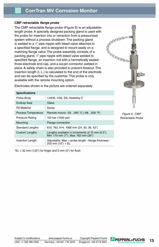
CMP retractable flange probeThe CMP retractable flange probe (Figure 6) is an adjustable-length probe. A specially designed packing gland is used with the probe for insertion into or retraction from a pressurized system without a process shutdown. The packing gland is welded to a 1” pipe nipple with bleed valve attached to a specified flange, and is designed to mount easily on a matching flange valve. The probe assembly consists of a packing gland, 1” pipe nipple with bleed valve welded to specified flange, an insertion rod with a hermetically sealed three-electrode end cap, and a six-pin connector welded in place. A safety chain is also provided to prevent blowout. The insertion length (I. L.) is calculated to the end of the electrode and can be specified by the customer. This probe is only available with the remote mounting option.
Electrodes shown in the picture are ordered separately.
Specifications
Probe Body 1.4435, 316L SS; Hastelloy C
Endcap Seal Glass
Fill Material Epoxy
Process Temperature Remote mount: -50…260 °C (-58…500 °F)
Pressure Rating 102 bar (1500 psi)
Mounting Flange connection
Standard Lengths 610, 762, 914, 1066 mm (24, 30, 36, 42”)
Custom Lengths Lengths available in increments of 10 mm (0.5”). Min: 170 mm (7”), Max: 762 mm (30”)
Insertion Length Adjustable, Max = probe length - flange thickness - 255 mm (10”) + EL
*EL = 32 mm (1.25”) for finger and 0 mm (0”) for flush

Subject to modifications www.pepperl-fuchs.us
USA: +1 330 486 0002 Singapore: +65 6779 9091
Copyright Pepperl+Fuchs
Germany: +49 621 776 2222
CorrTran MV Corrosion Monitor
14
Figure 7. CMP Retrievable Probe and Probe Adapter
CMP retrievable probeThe CMP retrievable probe (Figure 7) is a fixed-length probe. It is designed to be used with HPTM and MHTM high-pressure access systems. The probe assembly consists of an insertion rod with a hermetically sealed three-electrode end cap, a hollow plug nut, and a standard six-pin connector, which are all welded in place. The hollow plug nut on the probe screws into the hollow plug of the access system. This allows the probe to be installed in the process, using a retrieval tool and service valve, without process shutdown. The insertion length (I. L.) is calculated using one of the formulas bellow and must be specified by the customer. This probe is only available with the remote mounting option.
Electrodes shown in the picture are ordered separately.
Specifications
Probe Body 1.4435, 316L SS; Hastelloy C
Endcap Seal Glass
Fill Material Epoxy
Process Temperature Direct mount: -50…121 °C (-58…250 °F)
Remote mount: -50…260 °C (-58…500 °F)
Pressure Rating 245 bar (3600 psi)
Mounting UNS 1-14, 1” left-handed thread
Standard Lengths Length dependent on insertion length
Insertion Length Finger Electrodes
Top-of-the-line: I.L. = PD + WT + 44.5 mm (1.75”) Middle-of-the-line: I.L. = PD + WT + 22.25 mm (.875”) Bottom-of-the-line: I.L. = PD + WT
Insertion Length Flush Electrodes
I.L. = PD + WT + 44.5 mm (1.75”)
*EL = 32 mm (1.25”) for finger and 0 mm (0”) for flush*PD = Penetration depth, for flush mount PD = 0*WT = Wall thickness
Hollow plug and access fitting are ordered separately.

Subject to modifications www.pepperl-fuchs.us
USA: +1 330 486 0002 Singapore: +65 6779 9091
Copyright Pepperl+Fuchs
Germany: +49 621 776 2222
CorrTran MV Corrosion Monitor
15
3.3 Mounting safety procedures and hints The CorrTran MV must be installed in locations that are most susceptible to corrosion. In most cases, the highest levels of corrosion tend to occur where water is trapped or stagnant.
The electrodes selected must reflect the same metal properties as the piping or other components susceptible to corrosion. For example, in applications where the pipe is made of stainless steel and the water pump’s impeller is made of carbon steel, the impeller will corrode faster than the pipe. In this case, it is advisable to select electrodes that are made of the same material as the pump’s impeller.
3.3.1 Mounting requirements / scenarios
The transmitter should not be mounted in a pipe drop since the corrosive liquid may not be in full contact with the electrodes as shown in Figure 8.
CorrTran MV should be mounted in the riser of a pipe near an elbow where the velocity is the highest. In general, CorrTran MV should be mounted in pipes or tanks at locations of highest liquid velocity and constant immersion, shown in Figure 9. For velocities greater than 20 fps, the protruding finger electrodes
must be protected. As noted above, high fluid velocities can also cause unwanted turbulence in the pipe due to the extension of the probe. Using an adjustable CorrTran MV probe with electrodes mounted flush to the wall of the pipe will eliminate this problem.
Warning
Attention
OK!
Figure 8. CMC Transmitter Installation Figure 9. CMC Transmitter Installation

Subject to modifications www.pepperl-fuchs.us
USA: +1 330 486 0002 Singapore: +65 6779 9091
Copyright Pepperl+Fuchs
Germany: +49 621 776 2222
CorrTran MV Corrosion Monitor
16
CorrTran MV can be located at any point on the pipeline but should always be immersed in the corrosive material as shown in Figure 10.
Figure 10. Correct CorrTran MV Pipeline Position
A tee in the condensate return line (Figure 11) is a good location to mount CorrTran MV.
Figure 11. CorrTran MV Located in Tee
Subject to modifications www.pepperl-fuchs.us
USA: +1 330 486 0002 Singapore: +65 6779 9091
Copyright Pepperl+Fuchs
Germany: +49 621 776 2222
CorrTran MV Corrosion Monitor
17
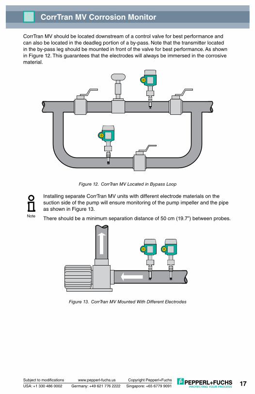
CorrTran MV should be located downstream of a control valve for best performance and can also be located in the deadleg portion of a by-pass. Note that the transmitter located in the by-pass leg should be mounted in front of the valve for best performance. As shown in Figure 12. This guarantees that the electrodes will always be immersed in the corrosive material.
Figure 12. CorrTran MV Located in Bypass Loop
Installing separate CorrTran MV units with different electrode materials on the suction side of the pump will ensure monitoring of the pump impeller and the pipe as shown in Figure 13.
There should be a minimum separation distance of 50 cm (19.7”) between probes.
Figure 13. CorrTran MV Mounted With Different Electrodes
Note

Subject to modifications www.pepperl-fuchs.us
USA: +1 330 486 0002 Singapore: +65 6779 9091
Copyright Pepperl+Fuchs
Germany: +49 621 776 2222
CorrTran MV Corrosion Monitor
18
In addition to pipes, a condensate flash tank, shown in Figure 14, is also a good application.
Figure 14. CorrTran MV Installed in a Condensate Flash Tank
The CorrTran MV transmitter is shown in the blow down of a Y-strainer in Figure 15, and the discharge side of the basket strainer is shown in Figure 16.
Figure 15. CorrTran MV Mounted in Y-Strainer
Figure 16. CorrTran MV Mounted in Basket Strainer
It is essential that P+F isolators are installed between the transmitter and the control system if the I/O card is not fully isolated from the ground. See section 4.3 for more information on the proper installation wiring.
Note

Subject to modifications www.pepperl-fuchs.us
USA: +1 330 486 0002 Singapore: +65 6779 9091
Copyright Pepperl+Fuchs
Germany: +49 621 776 2222
CorrTran MV Corrosion Monitor
19
3.4 Installation instructions 3.4.1 General
A trained specialist must perform the necessary installation and commissioning of CorrTran MV. Recognized rules of the technology and setup requirements must be maintained both during and after installation. Safety requirements must be observed during all installation steps.
If the pipe or vessel into which the CorrTran MV is to be inserted is under pressure and/or contains any hazardous substance, such as steam, caustic solutions, acids, toxins or other substances specified by OSHA as physical or health hazards, the pipe or vessel must first be depressurized, any hazardous substance purged therefrom, and appropriate lockout/tagout procedures observed in accordance with Section 1910.147 of the OSHA Regulations, before CorrTran MV can be installed. Failure to follow these procedures may result in serious injury or death.
CorrTran MV consists of three basic components:
Transmitter: A transmitter housing contains the electronics and provides the 4-20 mA with HART output signal.
Probe: There are two basic options, direct mount and remote mount. The remote mount probe is supplied with a 6’ or 12’ cable.
Electrodes: Either finger electrodes or electrodes flush to the probe end are used. Correctly chosen electrodes will corrode in the same manner as the metal being investigated. For accurate measurements, the electrodes must reflect the same metal properties as the metal being investigated.
3.4.2 Electrode installation The electrodes are shipped loose and must be installed hand-tight. Ensure that the Viton (standard) or Kalrez (on request) gaskets are in place prior to installing the electrodes. See Figure 17 for the electrode installation drawing.
Pepperl+Fuchs recommends changing the electrodes when they are at 50% of their useful life:
• Finger:0.4mmmaterialloss.Thismeansthatwithanaveragegeneralcorrosionrate of 16 mpy (0.4 mmpy) you would have to replace once a year.
• Flush:3.175mmmaterialloss.Thismeansthatwithanaveragegeneralcorrosion rate of 127 mpy (3.175 mmpy) you would have to replace once a year.
Figure 17. Electrodes and Viton Gaskets
Warning
Electrodes Viton Gaskets
Note

Subject to modifications www.pepperl-fuchs.us
USA: +1 330 486 0002 Singapore: +65 6779 9091
Copyright Pepperl+Fuchs
Germany: +49 621 776 2222
CorrTran MV Corrosion Monitor
20
Pepperl+Fuchs recommends cleaning the electrodes with rubbing alcohol or with another similar solution prior to operation to establish a reliable baseline for the transmitter electronics.
3.4.3 Probe installation CMP adjustable and fixed probes
1) Insert the probe into the pipe
2) Adjust to desired depth
3) Apply 1-1/4 turns from hand-tight to provide the seal as shown in Figure 18.
Figure 18. CMP Adjustable and Fixed Probe Mounting
For fixed type probes (without the compression fitting) only the 1-1/16” hex nut needs to be tightened.
A safety bracket is provided with every adjustable probe and must be installed before the process is put under pressure.
1-1/16” Hex Flat1-1/8” Hex Flat
Pipe
Attention
Note
Note

Subject to modifications www.pepperl-fuchs.us
USA: +1 330 486 0002 Singapore: +65 6779 9091
Copyright Pepperl+Fuchs
Germany: +49 621 776 2222
CorrTran MV Corrosion Monitor
21
CorrTran MV safety bracket assembly and installation
See Figure 19 for detailed drawings.
1) Screw nut (2) on to threaded rod (3).
2) Screw threaded rod (3) in to base plate (1).
3) Tighten nut (2) to lock threaded rod (3) in place.
4) Slide top plate (4) on to threaded rods (3).
NOTE: Top plate (4) must be assembled with label on top.
5) Place lock washer (5) and nut (6) on to threaded rod (3).
6) After sensor is mounted in to pipe, slide safety bracket into place and tighten nut (6) to lock bracket into place.
NOTE: If threaded rods (3) are too short for proper adjustment, contact the factory for replacement.
Figure 19. CorrTran MV Safety Bracket Assembly and Installation
LABEL MUST BEON TOP SIDE
DIRECT MOUNTCMC-SCD-01P/N 905776
REMOTE MOUNTCMC-SCR-01P/N 905777
TO TRANSMITTER
1
2
3
4
5
6

Subject to modifications www.pepperl-fuchs.us
USA: +1 330 486 0002 Singapore: +65 6779 9091
Copyright Pepperl+Fuchs
Germany: +49 621 776 2222
CorrTran MV Corrosion Monitor
22
CMP fixed flange probes
Insert the probe into the pipe, and tighten to flange specifications.
CMP retractable and retractable flange probes
The packing must be adjusted prior to mounting the packing gland to the process.
See Figure 20 for packing design details.
1) Loosen the locking nut. Slide locking nut and ferrule away form the retainer.
2) Loosen the jam nut. Turn retainer clockwise to tighten packing. The packing should be tightened until there is a resistance felt while sliding the insertion rod in and out. Table 2 summarizes the recommended torque for ambient temperature against water.
Pressure Rating 10.3 bar (150 psi)
34.5 bar (500 psi)
69 bar (1,000 psi)
103.5 bar (1,500 psi)
PTE (Teflon®) Packing
27.1 N-m (240 in-lb)
27.1 N-m (240 in-lb)
33.9 N-m (240 in-lb)
33.9 N-m (240 in-lb)
Grafoil Packing 20.4 N-m (240 in-lb)
20.4 N-m (240 in-lb)
27.1 N-m (240 in-lb)
27.1 N-m (240 in-lb)
Table 2. Recommended Torque Specifications
Do not over tighten packing. This will result in damage to the gland.
3) Tighten the jam nut, thereby locking the retainer in place.
4) Mount the packing gland on the nipple or flange and secure in place. The rod should be fully retracted at this time with the locking nut and ferrule clear of the retainer.
The following steps may require a certified pipe fitter for complete installation.
5) Open the process valve and check for packing leaks. If packing is leaking, shut the process valve, remove the packing gland, and readjust the packing gland using steps 3-5.
The packing may be tightened as long as the rod will slide in and out of the gland.
6) Insert to desired length. To lock the rod in place, secure the locking nut and ferrule.
7) Provided safety chain should now be between packing gland and probe body.
Attention
Note
Note

Subject to modifications www.pepperl-fuchs.us
USA: +1 330 486 0002 Singapore: +65 6779 9091
Copyright Pepperl+Fuchs
Germany: +49 621 776 2222
CorrTran MV Corrosion Monitor
23
Figure 20. Retractable Probe Packing Design
If the system is greater than 10.3 bar (150 psi) the use of an “Easy Tool Retracting System” is required to install and remove any retractable packing gland systems.
CMP retrievable probes
Refer to your removeable tool manual for instructions.
3.4.4 Mounting bracket installation A mounting bracket is available for the remote mount version of CorrTran MV. Its assembly and installation are shown in Figure 21. Please see section 6 for ordering information.
CorrTran MV safety bracket assembly and installation
See Figure 21 for detailed drawings.
1) To assemble locking clamps (5) onto mounting bracket (2), angle clamp (5) out, slide tabs into holes and angle back in.
2) Secure mounting bracket to sensor housing using two screws (6) provided.
For pipe mount:
1) Position mounting bracket (2) on pipe.
2) Using the U-bolt (1) provided, secure the mounting bracket (2) to the pipe using the lock washer (3) and nut (4) provided
For wall mount:
1) Secure mounting bracket (2) to the wall using a sturdy fastener (not provided).
Attention
Compression Washer
Packing Body Grafoil or V-Ring Packing
Insertion Rod
Locking Nut
Retainer
Jam Nut Ferrule

Subject to modifications www.pepperl-fuchs.us
USA: +1 330 486 0002 Singapore: +65 6779 9091
Copyright Pepperl+Fuchs
Germany: +49 621 776 2222
CorrTran MV Corrosion Monitor
24
Figure 21. CorrTran MV Mounting Bracket Assembly and Installation
4 WIRING 4.1 Quick wiring guide Before connection, please note the following:
•Thepowersupplymustbeidenticaltothedataonthenameplate.
•Switchoffpowersupplybeforeconnectingthedevice.
•Connectequipotentialbondingtotransmittergroundterminalbeforeconnectingthe device.
Connect CorrTran MV as follows:
1) Unscrew housing cover.
2) Insert cable through one of the ¾” NPT electrical ports.
3) Make electrical connection. See terminal assignment in Figure 22.
4) Screw on housing cover.
PIPE & WALL MOUNTCMC-PMB-01P/N 905775
1
2
3
4
5
6

Subject to modifications www.pepperl-fuchs.us
USA: +1 330 486 0002 Singapore: +65 6779 9091
Copyright Pepperl+Fuchs
Germany: +49 621 776 2222
CorrTran MV Corrosion Monitor
25
Figure 22. Transmitter Wiring
4.2 HART introduction Pepperl+Fuchs’ CorrTran MV probe supports the HART communication protocol. HART is an acronym for Highway Addressable Remote Transducer. The HART protocol makes use of the Bell 202 FSK standard to superimpose digital signals at a low level on top of the 4-20 mA signal. This enables two-way communication and makes it possible for additional information beyond just the normal process variable to be communicated to and from a smart field instrument.
4.3 Wiring with HART Due to the sensitive nature of corrosion measurement, it is important to provide good electrical isolation between the I/O system/power supply and each 4-20 mA/HART signal from CorrTran MV. For this reason, it is essential that Pepperl+Fuchs’ isolators be installed between the transmitter and the control system if the I/O card is not fully isolated from the ground. An intrinsic safety isolator used in combination with an intrinsically safe CorrTran MV mounted in a hazardous location meets this requirement, and additional isolation is not required. For all other applications, a signal conditioner capable of repeating the 4-20 mA/HART signals and providing at least 500 V of isolation must be used. If you are using CorrTran MV with a non-HART compatible I/O of data collection device, the KFD2-HLC-Ex1.D, HART Loop Converter, can integrate the three CorrTran MV variables into separate, independent 4-20 mA outputs. Illustrations of these wiring methods can be seen in Figures 23-25.
Please observe the following guidelines:
• Alwaysuseagroundedpowersupply(ontheACside).• EnsurethattheI/Ocardisisolatedfromground.
1 2
+ –
3
1 2+ –
3
3 mm(1/8 in)

Subject to modifications www.pepperl-fuchs.us
USA: +1 330 486 0002 Singapore: +65 6779 9091
Copyright Pepperl+Fuchs
Germany: +49 621 776 2222
CorrTran MV Corrosion Monitor
26
Figure 23. Connecting a HART Modem or a Handheld Device
Figure 24. Wiring with IS Barrier or Signal Conditioner
Figure 25. Wiring with the HART Loop Converter
4.4 Post-installation check After wiring the transmitter and connecting the probes, perform the following checks:
• Istheprobesecureandtightenedtospecifiedtorque?(Seesection3.4.3.)
• Havetheelectrodesbeencleaned?(Seesection3.4.2.)
• Istheterminalassignmentcorrect?(Seesection4.1.)
• Isthehousingcoverscrewedtight?
• IsthesignalconditionerinstalledbetweentheCorrTranMVandthePLC?
+ -
4-20 mA
HART handheld
PACTware
250 Ω
HART modem
DC power supply unit
or PLC
+ -
4-20 mA
HART modem
HART handheld
KFD2-STC4-Ex1PLC
+ -
4-20 mA
HART modem
HART handheld
KFD2-HLC-Ex1.DPLC

Subject to modifications www.pepperl-fuchs.us
USA: +1 330 486 0002 Singapore: +65 6779 9091
Copyright Pepperl+Fuchs
Germany: +49 621 776 2222
CorrTran MV Corrosion Monitor
27
5 CONFIGURATION AND COMMISSIONING 5.1 PACTware introduction PACTware is Pepperl+Fuchs’ latest generation of configuration software that makes it easy to program Pepperl+Fuchs’ equipment. In addition to becoming Pepperl+Fuchs’ single configuration tool, PACTware interfaces with HART-capable field instruments as well as bus systems such as PROFIBUS, Modbus and ControlNet.
PACTware offers many features that allow users to simplify plant documentation, generate trend curves, and monitor signals using HART data. Our software uses Device Tool Managers (DTM) to provide the interface into PACTware. Pepperl+Fuchs has created DTMs for HART-capable instruments by converting their Device Description (DD) into the appropriate DTM for use with PACTware.
5.2 Establishing communication with PACTware • ToestablishcommunicationbetweenyourCorrTranMVandotherdevicesusing
PACTware, you must first ensure that your modem is connected and you have access to a recent version of PACTware.
• ConnectHARTmodemasshowninsection4.3.
• OpenthelatestversionofPACTware.Figure26showsthemaindefaultscreenyouwill see when opening the program. (Please note: The CorrTran MV DTM will work with PACTWare version 2.4 or later.)
Figure 26. PACTware Main (Default) Screen
5.2.1 Connecting to the host computer To connect to the host computer with the HART modem:
• HighlighttheHOSTPC.
• Rightclickandselect‘Adddevice’fromthetoolbarandaddthe‘HARTCommunication’FDT as shown in Figure 27.

Subject to modifications www.pepperl-fuchs.us
USA: +1 330 486 0002 Singapore: +65 6779 9091
Copyright Pepperl+Fuchs
Germany: +49 621 776 2222
CorrTran MV Corrosion Monitor
28
Figure 27. ‘HART Communication’ FDT
5.2.2 CorrTran MV connection To establish a connection with your CorrTran MV unit(s):
• HighlighttheHARTCommunicator.• Rightclickandselect‘Device’>‘Adddevice’fromthetoolbarandaddthe‘CorrTranMV’
DTM. Your screen should appear as shown in Figure 28.
Figure 28. ‘CorrTran MV’ DTM

Subject to modifications www.pepperl-fuchs.us
USA: +1 330 486 0002 Singapore: +65 6779 9091
Copyright Pepperl+Fuchs
Germany: +49 621 776 2222
CorrTran MV Corrosion Monitor
29
5.2.3 Assigning the HART modem to the correct com port When loaded into PACTware, the HART modem defaults to Com 3 and will very likely need to be changed when using RS-232 or USB port modems.
USB connections will show up as com ports in the PACTWare environment. If you are not sure what com port your modem is using, go to your computer’s device manager by opening the following windows:
• ‘Controlpanel’>‘System’>‘Hardware’>‘DeviceManager’
• Expandthe‘Ports(COM&LPT)’tofindoutwhichcomportisbeingusedbythemodemUSB, as seen in Figure 29.
To change the com port on the HART Communication:
• DoubleclickonCOM3ontheleftsideofscreen.
• Changetothepropercomport,asseeninFigure30,andclickonapply.(Pleasenote:RS-232 ports are usually com 1.)
Figure 29. Device Manager Ports (COM & LPT)

Subject to modifications www.pepperl-fuchs.us
USA: +1 330 486 0002 Singapore: +65 6779 9091
Copyright Pepperl+Fuchs
Germany: +49 621 776 2222
CorrTran MV Corrosion Monitor
30
Figure 30. HART Modem USB Connected to a Different COM Port
5.2.4 Connection to the CorrTran MV unit. • Highlightthe‘CORRTRAN’totheleftofthescreen.
• Rightclickandselect‘Connect’fromthetoolbar.WaitseveralsecondsandtheCOMParametertabwilldisplaya‘#’symbol,andagreencheckmarkwillappearinthebottomleft indicating that the CorrTran MV has established communication with PACTware, as seen in Figure 31.
Figure 31. CorrTran MV Connected to PACTware

Subject to modifications www.pepperl-fuchs.us
USA: +1 330 486 0002 Singapore: +65 6779 9091
Copyright Pepperl+Fuchs
Germany: +49 621 776 2222
CorrTran MV Corrosion Monitor
31
5.3 CorrTran MV online variables and parameters Once a connection has been established, information from the CorrTran MV transmitter can be gathered.
5.3.1 Connection to online parameters To get online parameters:
• Highlightthe‘CORRTRAN’totheleftofthescreen.
• Rightclickandselect‘Parameters’>‘OnlineParameterization’fromthetoolbar.Yourscreen should appear as shown in Figure 32.
Figure 32. CorrTran MV Online Parameters (read only)
You can expand the online parameters to set up and show the configurations and other operational parameters important to your application.
5.3.2 Online parameters: process variables ThePACTware‘Processvariables’windowsarereadonlyandshowtheconfigurationsassociated with CorrTran MV’s three process variables. Each process variable has its own detailedscreen,listedinthetreeas‘PV’,‘SV’,and‘TV’:
• PV–PrimaryVariable: The primary variable screen includes percentage of range, loop current, average, and the sample count, which is how long the CorrTran MV has been poweredincommission.Figure33showsascreenshotofthe‘PV’page.
• SV–SecondaryVariable: This screen shows what the secondary variable is, its average, and the sample count.
• TV–TertiaryVariable: This screen provides information about the tertiary variable, which is set to measure conductance and cannot be changed. On this screen, you will see conductance measured in Siemens, along with its sample count.

Subject to modifications www.pepperl-fuchs.us
USA: +1 330 486 0002 Singapore: +65 6779 9091
Copyright Pepperl+Fuchs
Germany: +49 621 776 2222
CorrTran MV Corrosion Monitor
32
Figure 33. Process Variables – Primary Variable (read only)
5.3.3 Online variables: diag/service The‘DeviceVariables’screen,asshowninfigure34,providesanoverviewofallthreeprocess variables. This screen is read only.
Figure 34. Device Variables (read only)

Subject to modifications www.pepperl-fuchs.us
USA: +1 330 486 0002 Singapore: +65 6779 9091
Copyright Pepperl+Fuchs
Germany: +49 621 776 2222
CorrTran MV Corrosion Monitor
33
5.3.4 Online variables: device variables The Diagnostics/Service feature is password protected by default. To utilize this feature, youmustenablethepasswordasseeninFigure35.Thedefaultpasswordis‘managers’,and can be changed after the password has been enabled. After the password is enabled, you will see the screen shown in Figure 36.
Figure 35. Enabling the Password
Figure 36. Diag/Service Password Enabled

Subject to modifications www.pepperl-fuchs.us
USA: +1 330 486 0002 Singapore: +65 6779 9091
Copyright Pepperl+Fuchs
Germany: +49 621 776 2222
CorrTran MV Corrosion Monitor
34
Fromthe‘Diag/Service’menu,youhaveaccesstothefollowingfeatures:
• ‘Looptest’:allowsyoutoimpressacurrentsignalontheoutputofthetransmitter.
If the transmitter is being used for control, then it should be disabled. The Current selected for output will be imposed onto the loop.
• ‘ResetDevice’:recyclespower.
• ‘ResetFactDefault’:resetsparameterandpasswordstofactorydefaultsettings.
• ‘ResetCounterAverage’:resetssamplecountandaveragetozeroandthePVandSVare set to zero.
• ‘DeviceStatus’:indicatesanyparametersthatareoutofrangeornotworkingproperly.All the device status error codes are defined and expanded upon in Section 8, Troubleshooting, Table 4.
If device status circle, located at the top section of the PACTware screen, is green CorrTran MV currently has no errors. If the circle is red, CorrTran MV currently has anerrorthatcanbeviewedbyclickingthe‘DeviceStatus’button.SeeFigure37tolocate the device status circle.
Figure 37. Device Status
• ‘Password’:allowsyoutochange,disable/enable,orexitthepassword.
• ‘LoopCurrentTrim’:doesnotnormallyneedtobetrimmedandisdoneatthefactory.Consult factory if this is required.
Note
Attention

Subject to modifications www.pepperl-fuchs.us
USA: +1 330 486 0002 Singapore: +65 6779 9091
Copyright Pepperl+Fuchs
Germany: +49 621 776 2222
CorrTran MV Corrosion Monitor
35
5.3.5 Online variables: basic setup The‘BasicSetup’windowsallowbasicconfigurationforthefollowingparameters:
The password must be enabled in order to configure the CorrTran MV.
• ‘DeviceInformation’:allowsyoutoenterinformationaboutyourCorrTranMV.Someofthe fields, such as model and manufacturer, are read only.
Figure 38. Basic Setup – Device Information
• ‘DVAssignment’:allowsyoutoconfigurethePrimary(PV)andSecondary(SV)Variables as either general or localized corrosion, respectively. Remember, the Tertiary Variable(TV)isalwaysconductanceandcannotbechanged.Figure38showsthe‘DVAssignment’screeninthe‘BasicSetup’menu.
Note

Subject to modifications www.pepperl-fuchs.us
USA: +1 330 486 0002 Singapore: +65 6779 9091
Copyright Pepperl+Fuchs
Germany: +49 621 776 2222
CorrTran MV Corrosion Monitor
36
Figure 39. Basic Setup – Device Variable Assignment
• ‘RangeandUnits’:allowsyoutoconfigurethePVunitsandrange,whengeneralcorrosionisassignedasthePV.Figure39displaysthe‘RangeandUnits’window.
When localized corrosion is assigned as the PV, no units or range are selectable because localized corrosion is unitless and is on a scale from 0 to 1, with 0 being no localized corrosion and 1 being very high.)
Figure 40. Basic Setup – Range and Units
Note

Subject to modifications www.pepperl-fuchs.us
USA: +1 330 486 0002 Singapore: +65 6779 9091
Copyright Pepperl+Fuchs
Germany: +49 621 776 2222
CorrTran MV Corrosion Monitor
37
• ‘Damping’and‘Polladdr’:arelistedastwomenuitems,butactuallyappearononescreen. Damping is defaulted to 0.01 seconds, but does not affect the readings because the measurement cycle can range from 4 to 21 minutes.
5.3.6 Online variables: detailed setup Thedataneededtocompletethe‘detailedsetup’windowisenteredatthefactorybeforethe CorrTran MV is shipped, but you may need to reenter or change information in this window if the electrodes are changed to a different material or general or localized corrosion are eliminated from the measurement for faster update times. Figure 40 shows the‘DetailedSetup’configurationwindow.
Figure 41. Detailed Setup
Underthe‘detailedsetup’menu,youcanupdatevaluesinthefollowingwindows:
• ‘BUser’:BUserreferstotheBvalueorStern-Gearyvoltage,whichisdefaultedto 25.6 mV. B User is only relevant in LPR only mode. This value does not normally need to be changed.
• ‘AElectArea’:Thiswindowallowsyoutochangetheelectrodearea,whichisrequiredfor the corrosion calculation. The surface area is defaulted to 4.75 cm2 for the finger type electrodes. Flush mount electrodes are defaulted to 0.316 cm2.
• ‘KProbeConst’:referstotheKprobeconstant,orcorrosionconstantK.Thisvalueisdependent on the pipe’s metal properties and is required for the calculation process.
The default is 11597.63 mm * cm2
year * cm2
K = 3270.22 * (atomic mass of metal in grams)(# of electrons in the corrosion reaction) * (density in g/cm2)

Subject to modifications www.pepperl-fuchs.us
USA: +1 330 486 0002 Singapore: +65 6779 9091
Copyright Pepperl+Fuchs
Germany: +49 621 776 2222
CorrTran MV Corrosion Monitor
38
See Table 5 in the Appendix for factory calculated K values of common electrode materials.
• ‘AlarmConfig’:ThisscreencontrolsthesettingsforanalarmthatactivateswhenthePVcorrosion rate goes above or bellow the URV or LRV. The default is High/Auto, and the options are as follows:
• NoAlarm–Alarmisturnedoff
• High/Auto–Outputgoesto22.5mAandresetsautomatically.
• High/Manual–Outputgoesto22.5mAandresetsmanually.
• ‘DeviceMode’:Thisdeterminesthewaythegeneralcorrosioncalculationisperformedbythe CorrTran MV.
• Normal(HDA/LPR)–Aprocess-specificStern-Gearyvoltage(Bharm)iscalculatedwith every measurement cycle through HDA. This value is then implemented in the LPR corrosion rate calculation. This is the default setting and should be left intact to maintain the best accuracy.
• LPRonly–AuserdefinedStern-Gearyvoltage(‘BUser’)isspecifiedandusedforallLPR corrosion rate calculations.
• ‘MeasMode’:Certaincorrosionmeasurementscanbeturnedofftogiveafasterresponse if not required for the calculation. The two variables that can be switched off are general corrosion (GC) and localized corrosion (LC). Conductance is required for both corrosion types and cannot be turned off. If all three are used, the default is GC + LC + Cond. The three possible configurations and cycle times are:
• GC+LC+Cond.–General,Localized,Conductivity:21minutecycle
• GC+Cond.–General,Conductivity:4minutecycle
• LC+Cond.–Localized,Conductivity:17minutecycle
5.3.7 Online variables: REVIEW ‘REVIEW’allowsyoutoreviewallthesetupparametersfortheCorrTranMVtransmitterpreviouslydiscussed.Clickingoneitherthemain‘REVIEW’orsubmenuitemsbelowitwilldisplay the screen seen in Figure 41.
The actual measured B value (Stern-Geary value) is indicated at the bottom as the ‘CalculatedBvalue’
Note

Subject to modifications www.pepperl-fuchs.us
USA: +1 330 486 0002 Singapore: +65 6779 9091
Copyright Pepperl+Fuchs
Germany: +49 621 776 2222
CorrTran MV Corrosion Monitor
39
Figure 42. Review (read only)
5.3.8 Additional functions: process trend Toget‘ProcessTrend’:
• Highlightthe‘CORRTRAN’totheleftofthescreen.
• Rightclickandselect‘AdditionalFunctions’>‘ProcessTrend’fromthetoolbar.Yourscreen should appear as shown in Figure 42.
‘ProcessTrend’allowsyoutoplotallthreevariables(generalcorrosion,localizedcorrosion,and conductance) on the same graph over a user defined period of time.
Figure 43. Process Trend

Subject to modifications www.pepperl-fuchs.us
USA: +1 330 486 0002 Singapore: +65 6779 9091
Copyright Pepperl+Fuchs
Germany: +49 621 776 2222
CorrTran MV Corrosion Monitor
40
5.4 CorrTran MV test probe: CMP-TESTER Note: Using the CMP-TESTER is optional and not required for configuring and commissioning the CorrTran MV
Note: The CMP-TESTER is designed as a tool to verify proper functionality of the CorrTranMV. It is not a calibration device, and can not be used to scale the corrosion process data.
• DisconnecttheCorrTranMVtransmitterfromtheprobeortheremotemountcable.
• AttachtheCMP-TESTERtothetransmitterasseeninFigure44.
• InPactwareorusingtheEvaluationToolsetCorrTranparametersasfollows:
Device Mode = LPR Mode B Value = 25.6 mV
• AllowtheCorrTranMVtocompleteonewholesamplingcycle.
• FromthePACTwareCorrTranMVREVIEWscreen(seepage40)collectthefollowingdata: A Elect Area K Probe Const Calculated B Value
• FromthePACTwareCorrTranMVOnlineParametersscreen(seepage32)readthecorrosion rate in mil/yr.
• ForAElectArea=4.75cm2 (finger style electrodes) use Equation 1
• ForAElectArea=0.316cm2 (flush style electrodes) use Equation 2
Equation1:CRcalc=B/12695•(K-7)
Equation2:CRcalc=B/846•(K+1.4)
Where:
CRcalc is the calculated corrosion rate in mil/yr, B is the Calculate B value, and K is the K probe constant.
If the CRcalc is +/- 1% of the corrosion rate obtained from the PACTware CorrTran MV Online Parameters screen, then CorrTran MV is operating within factory specifications. At this point remove the CMP-TESTER and reattach the transmitter to the probe or the remote mount cable.
Note
CorrTran MV test probe

Subject to modifications www.pepperl-fuchs.us
USA: +1 330 486 0002 Singapore: +65 6779 9091
Copyright Pepperl+Fuchs
Germany: +49 621 776 2222
CorrTran MV Corrosion Monitor
41
6 REPLACEMENT PARTS AND ACCESSORIES 6.1 CorrTran MV parts Please submit the serial tag number on the nameplate when ordering replacement parts for CorrTran MV.
If the pipe or vessel into which the CorrTran MV is to be inserted is under pressure and/or contains any hazardous substance, such as steam, caustic solutions, acids, toxins or other substances specified by OSHA as physical or health hazards, the pipe or vessel must first be depressurized and any hazardous substance purged therefrom, and appropriate lockout/tagout procedures observed in accordance with Section 1910.147 of the OSHA Regulations, before CorrTran MV can be removed or the electrodes replaced. Failure to follow these procedures may result in serious injury or death.
6.1.1 Transmitter replacement
Warning
C M T M - A 2 I H -
Certificates
D2 cCSAus, NI, Cl. I,II,III; Div. 2, Group A-D
Ex cCSAus, EX, Cl. 1; Div. 1,2; Group A-D
GP gneral purpose
IS cCSAus, IS, Cl. I, II, III; Div. 1, 2; Group A-D
II 1G EEx ia IIC T4
Transmitter Mounting
1 direct mount
2 remote mount (cable not included)
Electrical Output
IH 4-20 mA, HART
Housing
A2 aluminum housing, Nema 4x, 3/4" NPT
Corrosion Type
M Multivariable

Subject to modifications www.pepperl-fuchs.us
USA: +1 330 486 0002 Singapore: +65 6779 9091
Copyright Pepperl+Fuchs
Germany: +49 621 776 2222
CorrTran MV Corrosion Monitor
42
6.1.2 Probe replacement
*Probe Mounting Guide and Electrode Material Guide can be found in the Appendix
C M P - - /
Insertion Length (fixed probes only)
in inches, 5" … 28", in 0.2" increments
050 5.0"
052 5.2"
…
278 27.8"
280 28.0"
in mm, 130mm … 710mm, in 5mm increments
130 130mm
135 135mm
…
705 705mm
710 710mm
Electrode Material
0A… see electrode material guide
*only needs to be specified for flush mounted electrodes
Probe Length
050* 5", 3/4" NPT
080 8", 3/4" NPT
110* 11", 3/4" NPT
120 12", 3/4" NPT or Flange
180 18", 3/4" NPT or Flange
240 24", 1" NPT, 3/4" NPT, or Flange
300 30", 1" NPT, 3/4" NPT, or Flange
127* 127 mm, 3/4" NPT
204 204 mm, 3/4" NPT
280* 280 mm, 3/4" NPT
305 305 mm, 3/4" NPT or Flange
457 457 mm, 3/4" NPT or Flange
610 610 mm, 1" NPT, 3/4" NPT, or Flange
762 762 mm, 1" NPT, 3/4" NPT, or Flange
ADP Retrievable Probe Electrical Adaptor
*epoxy probe only
Probe Mounting
See probe mounting guide
Measurement Unit, Probe Material
CB inches, 1.4435, 316L
CC inches, hastelloy C
CF inches, epoxy glass
DB mm, 1.4435, 316L
DC mm, hastelloy C
DF mm, epoxy glass
HF HF applications, no glass seal
CS Special, consult factory
Process Connection
A31 1", flange ANSI B 16.5, 150 lbs
A32 1", flange ANSI B 16.5, 300 lbs
A61 2", flange ANSI B 16.5, 150 lbs
A62 2", flange ANSI B 16.5, 300 lbs
F61 DN40 PN6 Form B Flange
F65 DN40 PN40 Form B Flange
N21 3/4" NPT, ANSI B 1.20.1, 1.4435/316L
N2P 3/4" NPT, ANSI B 1.20.1, adj. thread, nylon
N31 1" NPT
U31 UNS 1-14, 1" left handed thread
XXX Special Version
*Consult factory for other available options

Subject to modifications www.pepperl-fuchs.us
USA: +1 330 486 0002 Singapore: +65 6779 9091
Copyright Pepperl+Fuchs
Germany: +49 621 776 2222
CorrTran MV Corrosion Monitor
43
6.1.3 Electrode replacement – finger electrodes
*Electrode Material Guide can be found in the Appendix
Electrodes are sold in a pack of 3.
6.1.4 Remote mount cable replacement
C M C -
Electrode Material
0A… see electrode material guide
Note
C M C - R / 0 2 -
Cable Length
6 remote mount with 1.8m (6') cable
12 remote mount with 3.6m (12') cable

Subject to modifications www.pepperl-fuchs.us
USA: +1 330 486 0002 Singapore: +65 6779 9091
Copyright Pepperl+Fuchs
Germany: +49 621 776 2222
CorrTran MV Corrosion Monitor
44
6.2 HART accessories For installations requiring more then one transmitter, Pepperl+Fuchs offers a wide variety of HART multiplexers and termination boards for wiring to a PLC or DCS system. The multiplexers are available in 16 and 32 channel options.
Model Description
KFD2-HMM-16 16-channel MUX master
KFD0-HMS-16 16-channel slave
Please contact Pepperl+Fuchs for termination board selection.
6.3 Surge protection and IS barriers Using an intrinsically safe transmitter in a hazardous area requires an IS barrier. Pepperl+Fuchs offers the following styles of isolated barriers:
Model Description
KFD2-HLC-Ex1.D IS HART loop converter with 3 distinct 4-20 mA outputs
KCD2-STC-Ex1 1-channel IS isolator
KFD2-STC4-1 1-channel non-IS signal conditioner
KFD2-STC4-1.20 1- input 2- output non-IS signal conditioner
KFD2-STC4-Ex1 1-channel IS isolator
KFD2-STC4-Ex2 2-channel IS isolator
KFD2-STC4-Ex1.20 1- input 2- output IS isolator
KFU8-CRG-1.D 4-20 mA non-IS limit alarm
KFU8-CRG-Ex1.D 4-20 mA IS limit alarm
For installations requiring surge or lightning protection, use the above barriers in conjunction with one of these surge barriers:
Model Description
K-LB-1.30 1-channel Safe Zap surge barrier
K-LB-2.30 2-channel Safe Zap surge barrier
FN-LB-I 1-channel, screw-in type surge barrier for field mounting

Subject to modifications www.pepperl-fuchs.us
USA: +1 330 486 0002 Singapore: +65 6779 9091
Copyright Pepperl+Fuchs
Germany: +49 621 776 2222
CorrTran MV Corrosion Monitor
45
6.4 Additional accessories
Model Description
905820 Safety label
US-HI-321 USB HART modem
CMC-SCD-01 Safety bracket for direct mount probes
CMC-SCR-01 Safety bracket for remote mount probes
CMC-PMB-01 Wall or pipe mounting bracket for remote mounted transmitters
CMD-DL-Ex1 Safe area mountable data logger
CMD-DR2-Ex1 Zone 2 mountable video-graphic data recorder
CMC-SR2159ER36 36” easy tool retraction system for use with retractable probes
CMP-TESTER CorrTran MV test probe
*Consult factory for information on access fittings, the retrieval tool, and the service valve for use with retrievable probes
*Consult factory for information on pipe nipples and ball valves for use with the installation and mounting of retractable probes.
7 SYSTEM SPECSApplicationThe CorrTran MV performs continuous (electro-chemical) corrosion measurement of liquids and gasses. Probes are available in several different materials and process connections:
• Epoxyglassprobe:3/4”NPTadjustablenylonfitting
• Adjustableprobe:3/4”NPTfitting,availablein316LSSandHastelloyC
• Fixedprobe:3/4”NPTfittingandflangesstartingat1”ANSIB16.5150lbs,availablein316L SS and Hastelloy C
• Retractableprobe:Adjustable,1”femaleNPTfittingandflangesstartingat1”ANSIB16.5 150 lbs, available in 316L SS and Hastelloy C
• Retrievableprobe:Fixed,UNS1-141”lefthandthread,availablein316LSSandHastelloy C
Function and System DesignMeasuring Principle: The CorrTran MV utilizes state-of-the-art algorithms and data analysis techniques to accurately measure general corrosion rate and pitting. To improve the performance of the industry-accepted Linear Polarization Resistance (LPR) technique, the Harmonic Distortion Analysis (HDA) is used to calculate and update a process-specific Stern-Geary variable (Bharm) every measurement cycle. To further enhance the performance, an application-specific Stern-Geary variable (B-value) is calculated and updated every measuring cycle. There is no need to manually update the B-value because of process changes. During the measurement cycle, CorrTran MV also performs an automated Electrochemical Noise (ECN) measurement that provides a localized corrosion (pitting) measurement. At the completion of each measurement cycle, the respective corrosion rate and pitting value in the form of a 4-20 mA/HART signal is produced and made available to plant personnel.
Equipment ArchitectureSee page 26, section 4.3 Wiring with HART.

Subject to modifications www.pepperl-fuchs.us
USA: +1 330 486 0002 Singapore: +65 6779 9091
Copyright Pepperl+Fuchs
Germany: +49 621 776 2222
CorrTran MV Corrosion Monitor
46
Technical dataInput
Measured Variable •Generalcorrosion:Electro-chemicalcorrosionthatproceedsmoreorless uniformly over the surface of the material exposed to the corrosive environment.
•Localizedcorrosion(pitting):Electro-chemicalcorrosionthatoccursatdiscrete sites on the material exposed to the corrosive environment.
•Conductance:Thereciprocalofthesolutionresistance.Itisameasureof how easily electricity flows along a certain path through an electrical element.
Measuring Range •Generalcorrosion:0...1000mpy(0...25mmpy),0...40mpy(0...1mmpy) default value
•Localizedcorrosion(pitting):Unitlessnumberfrom0...1,with0beingno localized corrosion and 1 being very high.
•Conductance:Notadjustable.MeasuredinSiemens.
Output
Output Signal •4-20mAwithHARTprotocol,2-wire
Signal on Alarm Errorinformationcanbeaccessedviathefollowinginterfaces:•Currentoutput,22.5mA•Digitalinterface
Auxiliary Energy
Electrical Connection Housing F 12 with additionally sealed terminal compartment for standard, EEx ia, Intrinsically Safe (IS), or Nonincendive (NI)
Load HART Minimum load for HART communication: 250 Ω
Cable Entry See page 25, Section 4.1 Quick Wiring Guide
Supply Voltage 11-30 VDC
Rated Operating Voltage 11 VDC min at max loop current
Connectable Load Max. load at 24 VDC: 575 Ω with high alarm / 650 Ω without high alarm
B-Value (Start-up) 25.6 mV
Performance Characteristics
Reference Operating Conditions
•Temperature:-50°Cto+70°C(-58°Fto+158°F)
•Pressure:240bar(3600psi)•SolutionConductance:Min4μS
•GeneralCorrosionRate:0...1000mpy(0...25mmpy)
Accuracy •Voltagemeasurementandelectrodeexcitation:<0.02%
•Currentmeasurement:<0.1%

Subject to modifications www.pepperl-fuchs.us
USA: +1 330 486 0002 Singapore: +65 6779 9091
Copyright Pepperl+Fuchs
Germany: +49 621 776 2222
CorrTran MV Corrosion Monitor
47
Technical data (continued)Operating Conditions
Operating Conditions
Installation Instructions See page 20, Section 3.4 Installation Instructions
Environment
Ambient Temperature Range
Ambient temperature for the transmitter:
•GP,NI,ISversion:-50°Cto+70°C(-58°Fto+158°F)
•EXversion:-40°Cto+70°C(-40°Fto+158°F)
Storage Temperature -40 °C to +70 °C (-40 °F to +158 °F)
Degree of Protection •Housing:IP66,NEMA4X
Vibration Resistance 10…1000 Hz, 0.2 g2/Hz acc. to DIN EN 600068-2-64
Cleaning of the Probe and Electrodes
See page 20, Section 3.4.2 Electrode Installation
Electromagnetic Compatibility
NAMUR NE21; EN 61326, 1999 Immunity standards meet EN61000 sections 3-2, 3-3, 4-2, 4-3, 4-4, 4-5, and 4-11
Process Conditions
Process Temperature Limits
See technical specifications for your probe, Section 3.3 Probe Specifications
Process Pressure Limits See technical specifications for your probe, Section 3.3 Probe Specifications
Process Flow Rate Limits •Fingerelectrodes:Max6.1mps(20fps)
•Flushelectrodes:Nolimitonelectrodes;dependentonmechanicalstrength of probe body in the flow.
Mechanical Construction
Design, Dimensions See page 7, Section 3.1 Dimensions
Weight Approx. 500 g (16.1 oz), transmitter housing
Material •Housing:Aluminum
•ProcessConnections:1.4401/316LSS,HastelloyC,orNylon
•Probe:1.4401/316LSS,HastelloyC,orepoxyglass;fillmaterialepoxy
•Endcapseal:Glass(standard)orepoxy(onrequest)
•Electrode:SeeElectrodeMaterialGuide
•O-ring:Viton(standard)orKalrez(onrequest)
Process Connection See page 5, Section 2.1.2 Key to Model Number
Human Interface
Operation Concept See page 26, Section 4.3 Wiring with HART. See page 28, Section 5 Configuration and Commissioning
Certificates and Approvals
CE Approval The measuring system meets the legal requirements of the EC-guidelines. Pepperl+Fuchs confirms the instrument passing the required tests by attaching the CE-mark
External Standards and Guidelines
EN 60529 protection class of housing (IP-code) EN61010 safety regulations for electrical devices for measurement, control, regulation, and laboratory use. EN61326 emissions (equipment class B), compatibility(appendixA–industrialarea)

Subject to modifications www.pepperl-fuchs.us
USA: +1 330 486 0002 Singapore: +65 6779 9091
Copyright Pepperl+Fuchs
Germany: +49 621 776 2222
CorrTran MV Corrosion Monitor
48
Technical data (continued)Ex Approval LCIE 05 ATEX 6097X, II 1G EEx ia IIC T4; for additional certificates see
www.pepperl-fuchs.com
CSA Approval cCSAuscertifiedforUSandCanada;Certificate#1563164:•IS:Cl.I,II,III;Div.1,2;GroupsA…G•NI:Cl.I,II,III;Div.2:GroupsA…G•EX:Cl.I;Div. 1,2; Groups A…D
IEC Approval
Patents U.S. patents: 7,239,156; 7,245,132; 7,265,559; 7,282,928
Ordering Information
Ordering Information P+F can provide detailed ordering information and information on the order codes on request
Accessories
Accessories See page 42, Section 6 Replacement Parts and Accessories
Supplementary Documentation
Supplementary Documentation
“Detecting and Interpreting Localized Corrosion Using CorrTran MV”

Subject to modifications www.pepperl-fuchs.us
USA: +1 330 486 0002 Singapore: +65 6779 9091
Copyright Pepperl+Fuchs
Germany: +49 621 776 2222
CorrTran MV Corrosion Monitor
49
8 TROUBLESHOOTING If you encounter problems configuring or using your CorrTran MV, consult the following troubleshooting table. If you continue to have problems, please contact your Pepperl+Fuchs representative for further assistance.
Symptom Cause/Procedures Solution
No 4-20 mA output Check voltage and compare it with the specifications on the nameplate. Connect the correct voltage
Measuring correct voltage but unit does not respond
Check polarity on the terminals. See section 4.1
HART communication does not function
The communication resistor is not installed properly. See chapter 4.3: Wiring with HART
Table 3. CorrTran MV Basic Troubleshooting Guide
Device Status Codes
Description Troubleshooting
PV out of limits The primary variable has exceeded either the LRV or URV.
This can only happen if General Corrosion is assigned to the PV and the ranges are not set properly. Extend the range values to include current data point. See section 3.3.2 for more information.
SV or TV out of limits
The secondary or tertiary variable has exceeded either the LRV or URV
This can only happen if General Corrosion is assigned to the SV and the ranges are not set properly. Extend the range values to include current data point. See section 3.3.2 for more information. The TV cannot be out of limits because it has no limits.
Analog output saturated
The analog output has reached either its minimum or maximum
This can only happen if the alarm mode is off and the PV exceeds its LRV or URV.
Analog output fixed
The analog output signal has been set to a fixed mA value.
This is a result of setting the Loop Current to a fixed value on the tools tab. See section 3.3.4 for more information.
More status available
This flag indicates that one or more of the flags in the More Field Device Status section are set
Information only.
Cold start This flag is set after power has been recycled for one communication transaction.
Information only.
Configuration changed
A change has been made to the CorrTran MV configuration.
This can be reset by pressing the Reset Config Changed Flag on the device status tab. See section 3.3.3 for more information.
Device malfunction
This flag indicates that one or more of the flags in the Device Malfunction section are set.
Information only.
Table 4. Device Status Codes Troubleshooting Guide (continued on next page)

Subject to modifications www.pepperl-fuchs.us
USA: +1 330 486 0002 Singapore: +65 6779 9091
Copyright Pepperl+Fuchs
Germany: +49 621 776 2222
CorrTran MV Corrosion Monitor
50
Device Status Codes
Description Troubleshooting
LPR only mode The CorrTran MV has been configured to operate in LPR mode for its general corrosion calculation.
Device mode is by default Normal (HDA/LPR) and should be left that way to maintain the best accuracy for all process variables. See section 3.3.2 for more information.
High localized corrosion detected
The localized corrosion rate is above 0.3.
Information only.
B value from Harm. Out of range
The calculated B value based on the HDAisoutrange(10mV<B<62.5mV).
In some rare occasions the HDA calculation might not give a plausible result. Switch to LPR only mode if this flag persists to stay on. See section 3.3.4 for more information.
Conductance out of range
The measured solution conductance islowerthan4μS.Thisequalsaconductivityofapproximately1μS/cmfor finger electrodes.
TheCorrTranMVneedsatleast4μSof solution conductance or solution conductivityof1μS/cmforfullaccuracy. This can also be an indication that there is too much build up on the surface of the electrodes and they may need to be cleaned or they may not be fully immersed in the process fluid.
Cell offset voltage overflow
The CorrTran MV has detected a voltage difference between the three electrodes which is too high to compensate.
Typically this is an indication that there is too much build up on the surface of the electrodes and they need to be cleaned or that they have exceeded their useful life and should be replaced.
Corrosion rate calculation not possible
The CorrTran MV was not able to get any useful data.
Check the electrodes for debris, check for other flags, and make sure that the electrodes are fully immersed.
Electrode balance out of range
Due to an extremely high unbalanced potential (voltage difference) of the electrodes, the CorrTran MV is drawing more power from the loop than available.
One way to deal with this problem is to set the loop current to a fixed value (max is 20 mA). This should only occur under very rare circumstances, where the corrosion rate is very small (loop current is approx. 4 mA) but at the same time there is a huge potential difference between the electrodes. This can indicate contamination of one or more electrodes, corrosion masking effects of buildup, or that one electrode is bent or missing from the probe.
Harmonics out of range
The HDA did not provide any valid results.
In some rare occasions the HDA calculation might not give a plausible result. Switch to LPR only mode if this flag persists to stay on. See section 3.3.4 for more information.
Internal failure Hardware failure detected Replace transmitter
ADC failure ADC failure detected Replace transmitter
Memory failure Memory failure detected Replace transmitter
Table 5. Device Status Codes Troubleshooting Guide (continued from previous page)

Subject to modifications www.pepperl-fuchs.us
USA: +1 330 486 0002 Singapore: +65 6779 9091
Copyright Pepperl+Fuchs
Germany: +49 621 776 2222
CorrTran MV Corrosion Monitor
51
9 MEASURING PRINCIPLE
Figure 44. CorrTran MV Corrosion Cell
General corrosionLinear Polarization Resistance (LPR) is based on the fact that in a corroding electrode the relationship between icorr and the polarization resistance is give by the following equation:
icorr = BRp
, where Rp = ∆E∆I
with ∆E being the applied voltage and ∆I the resulting current.
Harmonic Distortion Analysis (HDA) allows CorrTran MV to determine icorr without using the Tafel slopes (ba, bc). This is typically done by applying a low frequency sinusoidal voltage and determining the distance of the resulting current.
CorrTran MV accurately measures the general corrosion rate by implementing Harmonic Distortion Analysis (HDA) to improve the performance of Linear Polarization Resistance (LPR). A process-specific Stern-Geary voltage (Bharm) is calculated with every measurement cycle through HDA. This value is then implemented in the LPR corrosion rate calculation resulting in a highly accurate self adjusting, process specific corrosion rate calculation. CorrTran MV can measure the general corrosion rate from 0 … 1000 mpy (0 … 25 mmpy).
Localized Corrosion (Pitting)Electrochemical Noise (ECN) is the method of monitoring spontaneous fluctuations generated at the interface of the corroding metal and process solution. As localized corrosion occurs, these fluctuations increase.
The CorrTran MV monitors for these fluctuations on the electrode surfaces for 17 minutes. It then performs a statistical analysis resulting in a unitless pitting factor value between 0 and 1. A pitting factor of nearly 0 represents no localized corrosion activity and a pitting factor of 1 represents high localized corrosion activity. Independent studies have revealed that a sustained pitting factor of greater than 0.3 is cause for concern and you should investigate the source of the elevated Localized Corrosion rate. For more information on the interpretation of localized corrosion please review our white paper: “Detecting and Interpreting Localized Corrosion Using CorrTran MV.”
Fe
Anodicsite
Cathodicsite
Fe2+
2H+
H2
Icorr 2e-

Subject to modifications www.pepperl-fuchs.us
USA: +1 330 486 0002 Singapore: +65 6779 9091
Copyright Pepperl+Fuchs
Germany: +49 621 776 2222
CorrTran MV Corrosion Monitor
52
ConductanceSolution resistance is a measure of how easily electricity flows along a certain path through an electrical element. The reciprocal of the solution resistance is solution conductance.
The CorrTran MV measures solution resistance in order to more accurately calculate the general corrosion rates. As an added feature CorrTran MV provides you with the solution conductance in units of Siemens as the tertiary variable that is not scalable. CorrTran MV requiresaminimumsolutionconductanceof4μSinordertoprovidereliablecorrosiondata.
The solution conductance value that CorrTran MV provides can be used to approximate solution conductivity by this relationship:
Conductivity ( Scm ) ≈ Conductance (S)
19
Solution conductivity is a function of distance. As the electrodes corrode, their sizes and geometry change causing this correlation to deteriorate. The CorrTran MV should not be considered as a replacement for standard conductivity meters.

Subject to modifications www.pepperl-fuchs.us
USA: +1 330 486 0002 Singapore: +65 6779 9091
Copyright Pepperl+Fuchs
Germany: +49 621 776 2222
CorrTran MV Corrosion Monitor
53
10 APPENDIX A
Table 6. Electrode Material Guide
CorrTran electrode materials
Electrode Material K-Value UNS Number P+F Model NumberAluminum
1100 10940.96 A91100 CME-0N2024 11400.51 A92024 CME-0O7075 A97075 CME-1O
Carbon Steel & Alloys1010 11486.66 G10100 CME-0S1018 11597.63 G10180 CME-0A1020 11401.49 G10200 CME-1TC4130 11283.76 G41300 CME-1RA53 Grade B 11583.07 K03005 CME-0BASTM A105 11298.74 K03504 CME-0RA36 11368.92 K02600 CME-0VA285 Grade C 11359.95 K02801 CME-1Q
Pipe Steel & APIA106 Grade B 11342.61 K03006 CME-0UAPI 5L Grade B 11441.28 – CME-0WAPI 52X-65 11440.94 – CME-1CAPI 5L X52 (STE 360.7) 11443.31 – CME-1FAPI 5L X60 11444.40 – CME-1HAPI 5L Grd A 11443.89 – CME-1LAPI 5L X42 11429.12 – CME-1N
Stainless Steel304 11334.57 S30400 CME-0C304L 11342.80 S30403 CME-0D316 11513.39 S31600 CME-0E316L 11519.53 S31603 CME-0F316 Ti 11382.15 S31635 CME-1M317L 11400.62 S31703 CME-1G904L 11287.19 N08904 CME-1K254SMO 11306.19 – CME-1S-K4079
Copper AlloysCDA715 (Cu/Ni 70/30) 11337.86 C71500 CME-0ICDA110ETP (99.9 Cu) 11686.71 C11000 CME-0JCDA706 (Cu/Ni 90/10) 11513.44 C70600 CME-0KCDA687 (aluminum brass) 12411.53 C68700 CME-0LCDA443 (ARS AD.Brass) 12324.74 C44300 CME-0MCDA220 Bronze C22000 CME-1P
Super AlloysHastelloy C-276 11666.48 N10276 CME-0Q
Zinc AlloysZinc Z15001 CME-0Z

Subject to modifications www.pepperl-fuchs.us
USA: +1 330 486 0002 Singapore: +65 6779 9091
Copyright Pepperl+Fuchs
Germany: +49 621 776 2222
CorrTran MV Corrosion Monitor
54
Probe mounting guide
Key # Probe Style* Process Connection Transmitter Mounting Electrode Style O-ring
MaterialA Fixed NPT, flange Direct Standard finger VitonB Fixed NPT, flange Remote Standard finger VitonC Adjustable NPT Direct Standard finger VitonD Adjustable NPT Remote Standard finger VitonE Retractable NPT Remote Standard finger VitonF Special design** — — — —G Fixed NPT, flange Direct Standard finger KalrezH Fixed NPT, flange Remote Standard finger KalrezI Adjustable NPT Direct Standard finger KalrezJ Adjustable NPT Remote Standard finger KalrezK Retractable NPT Remote Standard finger KalrezL Fixed NPT, flange Direct Flush N/AM Fixed NPT, flange Remote Flush N/AN Adjustable NPT Direct Flush N/AO Adjustable NPT Remote Flush N/AP Retractable NPT Remote Flush N/AQ Retractable Flange Remote Flush N/AR Retractable Flange w/ bleed valve Remote Flush N/AS Retractable Flange Remote Standard finger VitonT Retractable Flange w/ bleed valve Remote Standard finger VitonU Retractable special design** — — —V Retrievable UNS Remote Standard finger VitonW Retrievable UNS Remote Flush N/A
* Fixed - Fixed insertion length Adjustable - Adjustable insertion length Retractable - Adjustable insertion length, can be removed under pressure Retrievable - Adjustable insertion length, can be removed Other designs available upon request.
** Consult factory
Table 7. Probe Mounting Guide
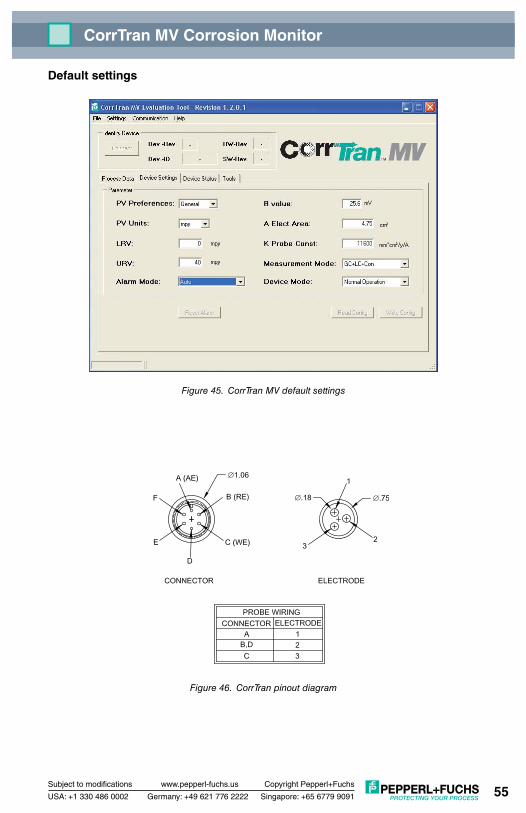
Subject to modifications www.pepperl-fuchs.us
USA: +1 330 486 0002 Singapore: +65 6779 9091
Copyright Pepperl+Fuchs
Germany: +49 621 776 2222
CorrTran MV Corrosion Monitor
55
Default settings
Figure 45. CorrTran MV default settings
Figure 46. CorrTran pinout diagram
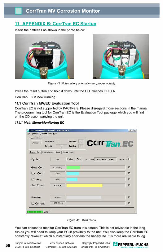
Subject to modifications www.pepperl-fuchs.us
USA: +1 330 486 0002 Singapore: +65 6779 9091
Copyright Pepperl+Fuchs
Germany: +49 621 776 2222
CorrTran MV Corrosion Monitor
56
11 APPENDIX B: CorrTran EC StartupInsert the batteries as shown in the photo below:
Figure 47. Note battery orientation for proper polarity
Press the reset button and hold it down until the LED flashes GREEN.
CorrTran EC is now running.
11.1 CorrTran MV/EC Evaluation ToolCorrTran EC is not supported by PACTware. Please disregard those sections in the manual. The programming tool for CorrTran EC is the Evaluation Tool package which you will find on the CD accompanying the unit.
11.1.1 Main Menu-Monitoring EC
Figure 48. Main menu
You can choose to monitor CorrTran EC from this screen. This is not advisable in the long run as you will need to keep your PC in proximity to the unit. You also keep the CorrTran EC constantly "awake" which substantially shortens the battery life. It is more advisable to log

Subject to modifications www.pepperl-fuchs.us
USA: +1 330 486 0002 Singapore: +65 6779 9091
Copyright Pepperl+Fuchs
Germany: +49 621 776 2222
CorrTran MV Corrosion Monitor
57
data internally to the CorrTran EC and then retrieve this data on a memory stick.
11.1.2 Device Settings Tab
Figure 49. Device settings tab
From the Device Settings Menu you can make the initial settings on the CorrTran EC and save them to the nonvolatile memory in the unit.
Timing Mode: Sets the data logging interval of CorrTran EC.
GC Units: General corrosion units. Choices are mils/year (mpy) or millimeters/year (mmpy).
Battery Type: Choose the battery type to match the ones you are using. For the Demo using the SAFT batteries choose 3.6 V Lithium.
Data to Log: Choose what you want logged internally to CorrTran EC.

Subject to modifications www.pepperl-fuchs.us
USA: +1 330 486 0002 Singapore: +65 6779 9091
Copyright Pepperl+Fuchs
Germany: +49 621 776 2222
CorrTran MV Corrosion Monitor
58
On the Corrosion Parameter panel, you may enter your own Stearn-Geary value for B value.
Figure 50. Corrosion parameter panel
A Elect Area: This parameter is the electrode area, it should remain 4.75 cm2 for standard finger electrodes and XXX cm2 for flush electrodes. For whatever reason, should you change the electrode area, this parameter should be updated to maintain the accuracy of the calculation.
K Probe Constant: You can update this value if you are using LPR Mode only. If you are using Normal Mode, the K constant will update automatically after the first measurement.
Measurement Mode: Selects which parameters are measured and therefore affect the speed in which the unit operates.
11.1.3 Retrieving Data From CorrTran ECTo retrieve data from CorrTran EC you must have a USB solid-state memory stick with at least 512 KB of available storage space.
Install the memory stick in the CorrTran EC. The green light will flash indicating a data transfer in progress.

Subject to modifications www.pepperl-fuchs.us
USA: +1 330 486 0002 Singapore: +65 6779 9091
Copyright Pepperl+Fuchs
Germany: +49 621 776 2222
CorrTran MV Corrosion Monitor
59
11.2 Hints on Extending Battery LifeBy comparison to CorrTran itself, the memory stick is a huge consumer of battery power and life. Your demo unit is shipped with very high-density, 3.6 V, Li-SOCl2 batteries. These batteries will operate CorrTran for months under typical use and allow retrieval of data on several occasions. Replacements are available from Pepperl+Fuchs. However, there may be a time when it is no longer possible to retrieve data from the unit. During this time, CorrTran will still log data. There is just insufficient battery capacity to retrieve the data from the memory. For this reason, we recommend that you take a spare set of batteries to the unit when you retrieve the data or connect the unit to auxiliary power.

Subject to modifications www.pepperl-fuchs.us
USA: +1 330 486 0002 Singapore: +65 6779 9091
Copyright Pepperl+Fuchs
Germany: +49 621 776 2222
CorrTran MV Corrosion Monitor
60
12 Notes


5 1
8
4
2
6
7
3
Subject to modifications • © 2012 PEPPERL+FUCHS, INC. • Printed in USA • Part No. 905681 Drawing No. 129-0239 (TDOCT-0970GENG ) 03/12
www.pepperl-fuchs.com
PROCESS AUTOMATION – PROTECTING yOUR PROCESS
Worldwide/German Headquarters Pepperl+Fuchs GmbH Mannheim · GermanyTel. +49 621 776 2222E-Mail: [email protected]
1
Asia Pacific HeadquartersPepperl+Fuchs PTE Ltd. SingaporeCompany Registration No. 199003130ETel. +65 6779 9091E-Mail: [email protected]
2
Central/Western Europe & Africa HeadquartersPepperl+Fuchs N.V. Schoten/Antwerp · BelgiumTel. +32 3 6442500E-Mail: [email protected]
3
Middle East HeadquartersPepperl+Fuchs M.E (FZE) Dubai · UAETel. +971 4 883 8378E-Mail: [email protected]
4
North/Central America Headquarters Pepperl+Fuchs Inc. Twinsburg · Ohio · USATel. +1 330 486 0002E-Mail: [email protected]
5
Northern Europe HeadquartersPepperl+Fuchs GB Ldt. Oldham · EnglandTel. +44 161 6336431E-Mail: [email protected]
6
Southern/Eastern Europe HeadquartersPepperl+Fuchs Elcon srl Sulbiate · ItalyTel. +39 039 62921E-Mail: [email protected]
7
South America HeadquartersPepperl+Fuchs Ltda. São Bernado do Campo · SP · BrazilTel. +55 11 4341 8448E-Mail: [email protected]
8
For over a half century, Pepperl+Fuchs has provided new concepts for the world of process automation. Our company sets standards in quality and innovative technology. We develop, produce and distribute electronic interface modules, Human-Machine Interfaces and hazardous location protection equipment on a global scale, meeting the most demand-ing needs of industry. Resulting from our world-wide presence and our high flexibility in production and customer service, we are able to offer complete individual solutions – wherever and whenever you need us. We are the recognized experts in our technologies – Pepperl+Fuchs has earned a strong reputation by supplying the world’s largest process industry companies with the broadest line of proven components for a diverse range of applications.