cos - citroen switchgearscitroenswitchgears.com/pdf/socomec/cat_cos-in.pdfcos on load changeover...
TRANSCRIPT
Cha
ngeo
ver
swit
ches
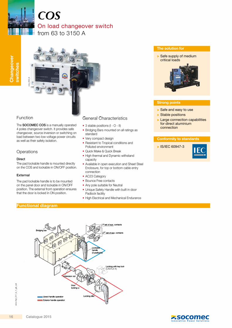
Function
The SOCOMEC COS is a manually operated 4 poles changeover switch. It provides safe changeover, source inversion or switching on load between two low voltage power circuits as well as their safety isolation.
Operations
DirectThe pad lockable handle is mounted directly on the COS and lockable in ON/OFF position.
External
The pad lockable handle is to be mounted on the panel door and lockable in ON/OFF position. The external front operation ensures that the door is locked in ON position.
General Characteristics
• 3 stable positions (I - O - II) • Bridging Bars mounted on all ratings as standard
• Very compact design • Resistant to Tropical conditions and Polluted environment
• Quick Make & Quick Break • High thermal and Dynamic withstand capacity
• Available in open execution and Sheet Steel Enclosure, for top or bottom cable entry connection
• AC23 Category • Bounce Free contacts • Any pole suitable for Neutral • Unique Safety Handle with built in door Padlock facility
• High Electrical and Mechanical Endurance
Function General Characteristics
COSOn load changeover switchfrom 63 to 3150 A
sirc
o-hp
l_01
1_b_
1_gb
_cat
cos_
002_
b
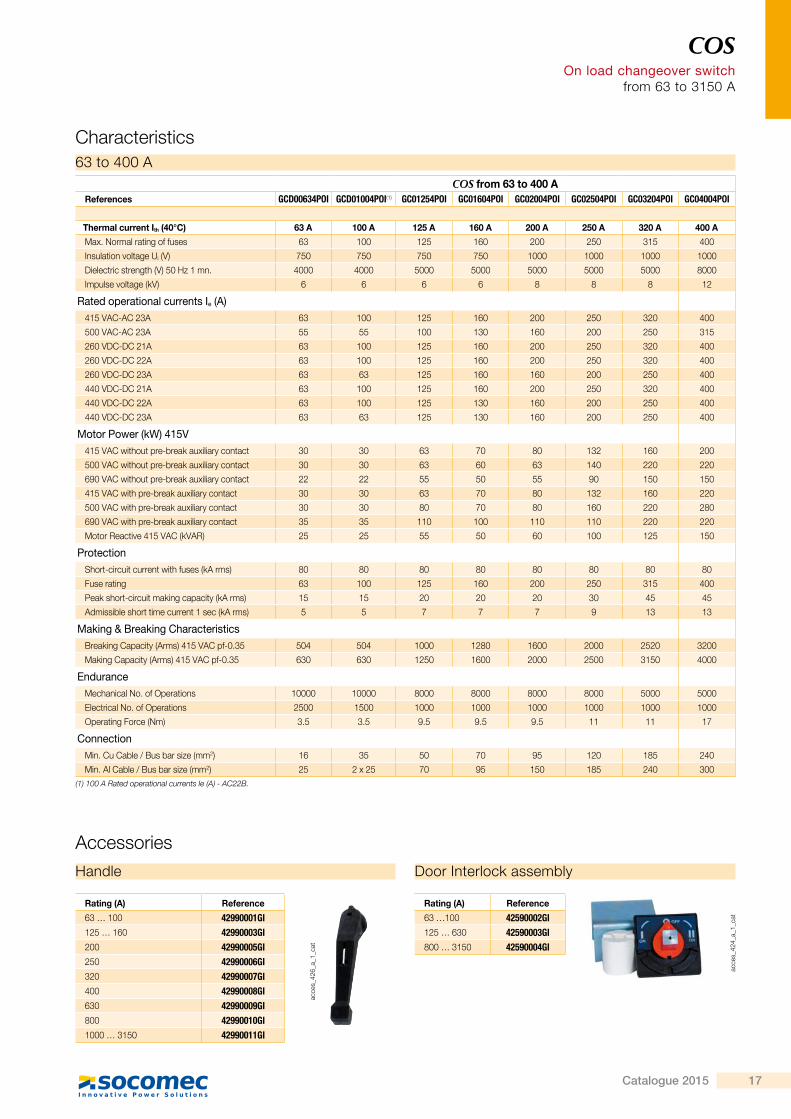
Functional diagram
> Safe supply of medium critical loads
The solution for
> Safe and easy to use > Stable positions > Large connection capabilities for direct aluminium connection
Strong points
> IS/IEC 60947-3
Conformity to standards
1st set of aux. contacts
2nd set of aux. contacts
Lockable handle(3 padlocks)
Locking with key lockLocking with key lock(CASTELL K)
Locking disc
Doorlocking U
Extension rod
Direct handle operation
Exterior handle operation
Bridging bar
(CASTLE K)
COSOn load changeover switch
from 63 to 3150 A
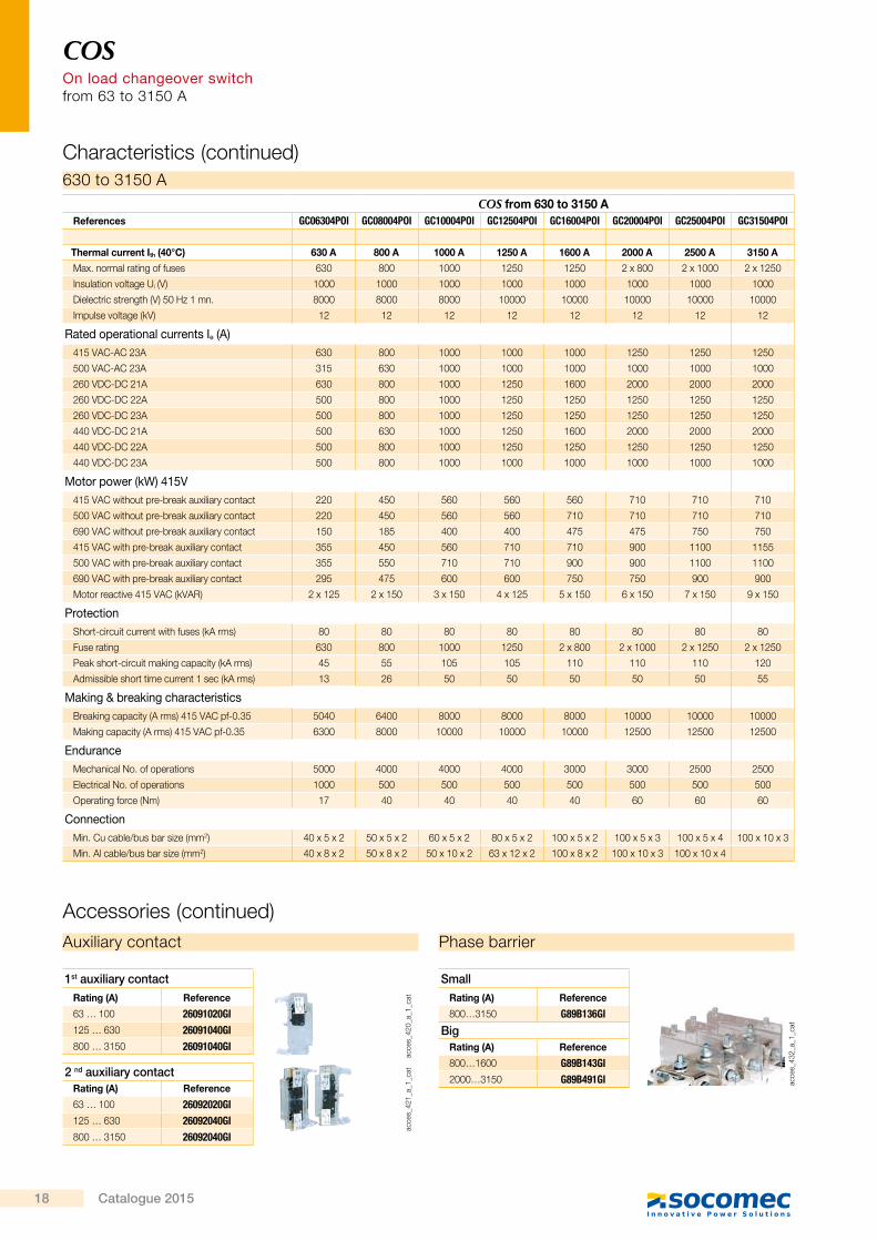
Characteristics
COS from 63 to 400 AReferences GCD00634POI GCD01004POI(1) GC01254POI GC01604POI GC02004POI GC02504POI GC03204POI GC04004POI
Thermal current Ith (40°C) 63 A 100 A 125 A 160 A 200 A 250 A 320 A 400 A
Max. Normal rating of fuses 63 100 125 160 200 250 315 400
Insulation voltage Ui (V) 750 750 750 750 1000 1000 1000 1000
Dielectric strength (V) 50 Hz 1 mn. 4000 4000 5000 5000 5000 5000 5000 8000
Impulse voltage (kV) 6 6 6 6 8 8 8 12
Rated operational currents Ie (A) 415 VAC-AC 23A 63 100 125 160 200 250 320 400
500 VAC-AC 23A 55 55 100 130 160 200 250 315
260 VDC-DC 21A 63 100 125 160 200 250 320 400
260 VDC-DC 22A 63 100 125 160 200 250 320 400
260 VDC-DC 23A 63 63 125 160 160 200 250 400
440 VDC-DC 21A 63 100 125 160 200 250 320 400
440 VDC-DC 22A 63 100 125 130 160 200 250 400
440 VDC-DC 23A 63 63 125 130 160 200 250 400
Motor Power (kW) 415V 415 VAC without pre-break auxiliary contact 30 30 63 70 80 132 160 200
500 VAC without pre-break auxiliary contact 30 30 63 60 63 140 220 220
690 VAC without pre-break auxiliary contact 22 22 55 50 55 90 150 150
415 VAC with pre-break auxiliary contact 30 30 63 70 80 132 160 220
500 VAC with pre-break auxiliary contact 30 30 80 70 80 160 220 280
690 VAC with pre-break auxiliary contact 35 35 110 100 110 110 220 220
Motor Reactive 415 VAC (kVAR) 25 25 55 50 60 100 125 150
ProtectionShort-circuit current with fuses (kA rms) 80 80 80 80 80 80 80 80
Fuse rating 63 100 125 160 200 250 315 400
Peak short-circuit making capacity (kA rms) 15 15 20 20 20 30 45 45
Admissible short time current 1 sec (kA rms) 5 5 7 7 7 9 13 13
Making & Breaking CharacteristicsBreaking Capacity (Arms) 415 VAC pf-0.35 504 504 1000 1280 1600 2000 2520 3200
Making Capacity (Arms) 415 VAC pf-0.35 630 630 1250 1600 2000 2500 3150 4000
EnduranceMechanical No. of Operations 10000 10000 8000 8000 8000 8000 5000 5000
Electrical No. of Operations 2500 1500 1000 1000 1000 1000 1000 1000
Operating Force (Nm) 3.5 3.5 9.5 9.5 9.5 11 11 17
ConnectionMin. Cu Cable / Bus bar size (mm2) 16 35 50 70 95 120 185 240
Min. Al Cable / Bus bar size (mm2) 25 2 x 25 70 95 150 185 240 300
63 to 400 A
Rating (A) Reference
63 … 100 42990001GI125 … 160 42990003GI200 42990005GI250 42990006GI320 42990007GI400 42990008GI630 42990009GI800 42990010GI1000 … 3150 42990011GI
AccessoriesHandle Door Interlock assembly
acce
s_42
4_a_
1_ca
t
Rating (A) Reference
63 …100 42590002GI125 … 630 42590003GI800 … 3150 42590004GI
(1) 100 A Rated operational currents Ie (A) - AC22B.
acce
s_42
6_a_
1_ca
t
16 Catalogue 2015
Cha
ngeo
ver
swit
ches
Function
The SOCOMEC COS is a manually operated 4 poles changeover switch. It provides safe changeover, source inversion or switching on load between two low voltage power circuits as well as their safety isolation.
Operations
DirectThe pad lockable handle is mounted directly on the COS and lockable in ON/OFF position.
External
The pad lockable handle is to be mounted on the panel door and lockable in ON/OFF position. The external front operation ensures that the door is locked in ON position.
General Characteristics
• 3 stable positions (I - O - II) • Bridging Bars mounted on all ratings as standard
• Very compact design • Resistant to Tropical conditions and Polluted environment
• Quick Make & Quick Break • High thermal and Dynamic withstand capacity
• Available in open execution and Sheet Steel Enclosure, for top or bottom cable entry connection
• AC23 Category • Bounce Free contacts • Any pole suitable for Neutral • Unique Safety Handle with built in door Padlock facility
• High Electrical and Mechanical Endurance
Function General Characteristics
COSOn load changeover switchfrom 63 to 3150 A
Terminal screens
1st set of aux. contacts
2nd set of aux. contacts
Lockable handle(3 padlocks)
Locking with key lockLocking with key lock(CASTELL K)
Locking disc
Doorlocking U
Terminal cage
Extension rod
Direct handle operation
Exterior handle operation
Bridging bar
sirc
o-hp
l_01
1_b_
1_gb
_cat
cos_
002_
b
Functional diagram
> Safe supply of medium critical loads
The solution for
> Safe and easy to use > Stable positions > Large connection capabilities for direct aluminium connection
Strong points
> IS/IEC 60947-3
Conformity to standards
COSOn load changeover switch
from 63 to 3150 A
Characteristics
COS from 63 to 400 AReferences GCD00634POI GCD01004POI(1) GC01254POI GC01604POI GC02004POI GC02504POI GC03204POI GC04004POI
Thermal current Ith (40°C) 63 A 100 A 125 A 160 A 200 A 250 A 320 A 400 A
Max. Normal rating of fuses 63 100 125 160 200 250 315 400
Insulation voltage Ui (V) 750 750 750 750 1000 1000 1000 1000
Dielectric strength (V) 50 Hz 1 mn. 4000 4000 5000 5000 5000 5000 5000 8000
Impulse voltage (kV) 6 6 6 6 8 8 8 12
Rated operational currents Ie (A) 415 VAC-AC 23A 63 100 125 160 200 250 320 400
500 VAC-AC 23A 55 55 100 130 160 200 250 315
260 VDC-DC 21A 63 100 125 160 200 250 320 400
260 VDC-DC 22A 63 100 125 160 200 250 320 400
260 VDC-DC 23A 63 63 125 160 160 200 250 400
440 VDC-DC 21A 63 100 125 160 200 250 320 400
440 VDC-DC 22A 63 100 125 130 160 200 250 400
440 VDC-DC 23A 63 63 125 130 160 200 250 400
Motor Power (kW) 415V 415 VAC without pre-break auxiliary contact 30 30 63 70 80 132 160 200
500 VAC without pre-break auxiliary contact 30 30 63 60 63 140 220 220
690 VAC without pre-break auxiliary contact 22 22 55 50 55 90 150 150
415 VAC with pre-break auxiliary contact 30 30 63 70 80 132 160 220
500 VAC with pre-break auxiliary contact 30 30 80 70 80 160 220 280
690 VAC with pre-break auxiliary contact 35 35 110 100 110 110 220 220
Motor Reactive 415 VAC (kVAR) 25 25 55 50 60 100 125 150
ProtectionShort-circuit current with fuses (kA rms) 80 80 80 80 80 80 80 80
Fuse rating 63 100 125 160 200 250 315 400
Peak short-circuit making capacity (kA rms) 15 15 20 20 20 30 45 45
Admissible short time current 1 sec (kA rms) 5 5 7 7 7 9 13 13
Making & Breaking CharacteristicsBreaking Capacity (Arms) 415 VAC pf-0.35 504 504 1000 1280 1600 2000 2520 3200
Making Capacity (Arms) 415 VAC pf-0.35 630 630 1250 1600 2000 2500 3150 4000
EnduranceMechanical No. of Operations 10000 10000 8000 8000 8000 8000 5000 5000
Electrical No. of Operations 2500 1500 1000 1000 1000 1000 1000 1000
Operating Force (Nm) 3.5 3.5 9.5 9.5 9.5 11 11 17
ConnectionMin. Cu Cable / Bus bar size (mm2) 16 35 50 70 95 120 185 240
Min. Al Cable / Bus bar size (mm2) 25 2 x 25 70 95 150 185 240 300
63 to 400 A
Rating (A) Reference
63 … 100 42990001GI125 … 160 42990003GI200 42990005GI250 42990006GI320 42990007GI400 42990008GI630 42990009GI800 42990010GI1000 … 3150 42990011GI
AccessoriesHandle Door Interlock assembly
acce
s_42
4_a_
1_ca
t
Rating (A) Reference
63 …100 42590002GI125 … 630 42590003GI800 … 3150 42590004GI
(1) 100 A Rated operational currents Ie (A) - AC22B.
acce
s_42
6_a_
1_ca
t
17Catalogue 2015
COS On load changeover switch from 63 to 3150 A
COS from 630 to 3150 AReferences GC06304POI GC08004POI GC10004POI GC12504POI GC16004POI GC20004POI GC25004POI GC31504POI
Thermal current Ith (40°C) 630 A 800 A 1000 A 1250 A 1600 A 2000 A 2500 A 3150 A
Max. normal rating of fuses 630 800 1000 1250 1250 2 x 800 2 x 1000 2 x 1250
Insulation voltage Ui (V) 1000 1000 1000 1000 1000 1000 1000 1000
Dielectric strength (V) 50 Hz 1 mn. 8000 8000 8000 10000 10000 10000 10000 10000
Impulse voltage (kV) 12 12 12 12 12 12 12 12
Rated operational currents Ie (A) 415 VAC-AC 23A 630 800 1000 1000 1000 1250 1250 1250
500 VAC-AC 23A 315 630 1000 1000 1000 1000 1000 1000
260 VDC-DC 21A 630 800 1000 1250 1600 2000 2000 2000
260 VDC-DC 22A 500 800 1000 1250 1250 1250 1250 1250
260 VDC-DC 23A 500 800 1000 1250 1250 1250 1250 1250
440 VDC-DC 21A 500 630 1000 1250 1600 2000 2000 2000
440 VDC-DC 22A 500 800 1000 1250 1250 1250 1250 1250
440 VDC-DC 23A 500 800 1000 1000 1000 1000 1000 1000
Motor power (kW) 415V 415 VAC without pre-break auxiliary contact 220 450 560 560 560 710 710 710
500 VAC without pre-break auxiliary contact 220 450 560 560 710 710 710 710
690 VAC without pre-break auxiliary contact 150 185 400 400 475 475 750 750
415 VAC with pre-break auxiliary contact 355 450 560 710 710 900 1100 1155
500 VAC with pre-break auxiliary contact 355 550 710 710 900 900 1100 1100
690 VAC with pre-break auxiliary contact 295 475 600 600 750 750 900 900
Motor reactive 415 VAC (kVAR) 2 x 125 2 x 150 3 x 150 4 x 125 5 x 150 6 x 150 7 x 150 9 x 150
ProtectionShort-circuit current with fuses (kA rms) 80 80 80 80 80 80 80 80
Fuse rating 630 800 1000 1250 2 x 800 2 x 1000 2 x 1250 2 x 1250
Peak short-circuit making capacity (kA rms) 45 55 105 105 110 110 110 120
Admissible short time current 1 sec (kA rms) 13 26 50 50 50 50 50 55
Making & breaking characteristicsBreaking capacity (A rms) 415 VAC pf-0.35 5040 6400 8000 8000 8000 10000 10000 10000
Making capacity (A rms) 415 VAC pf-0.35 6300 8000 10000 10000 10000 12500 12500 12500
EnduranceMechanical No. of operations 5000 4000 4000 4000 3000 3000 2500 2500
Electrical No. of operations 1000 500 500 500 500 500 500 500
Operating force (Nm) 17 40 40 40 40 60 60 60
ConnectionMin. Cu cable/bus bar size (mm2) 40 x 5 x 2 50 x 5 x 2 60 x 5 x 2 80 x 5 x 2 100 x 5 x 2 100 x 5 x 3 100 x 5 x 4 100 x 10 x 3
Min. Al cable/bus bar size (mm2) 40 x 8 x 2 50 x 8 x 2 50 x 10 x 2 63 x 12 x 2 100 x 8 x 2 100 x 10 x 3 100 x 10 x 4
630 to 3150 A
Characteristics (continued)
Auxiliary contact Phase barrier
Accessories (continued)
1st auxiliary contactRating (A) Reference
63 … 100 26091020GI125 … 630 26091040GI800 … 3150 26091040GI
SmallRating (A) Reference
800…3150 G89B136GI
BigRating (A) Reference
800…1600 G89B143GI2000…3150 G89B491GI
2 nd auxiliary contactRating (A) Reference
63 … 100 26092020GI125 … 630 26092040GI800 … 3150 26092040GI
acce
s_42
0_a_
1_ca
tac
ces_
421_
a_1_
cat
acce
s_43
2_a_
1_ca
t
COSOn load changeover switch
from 63 to 3150 A
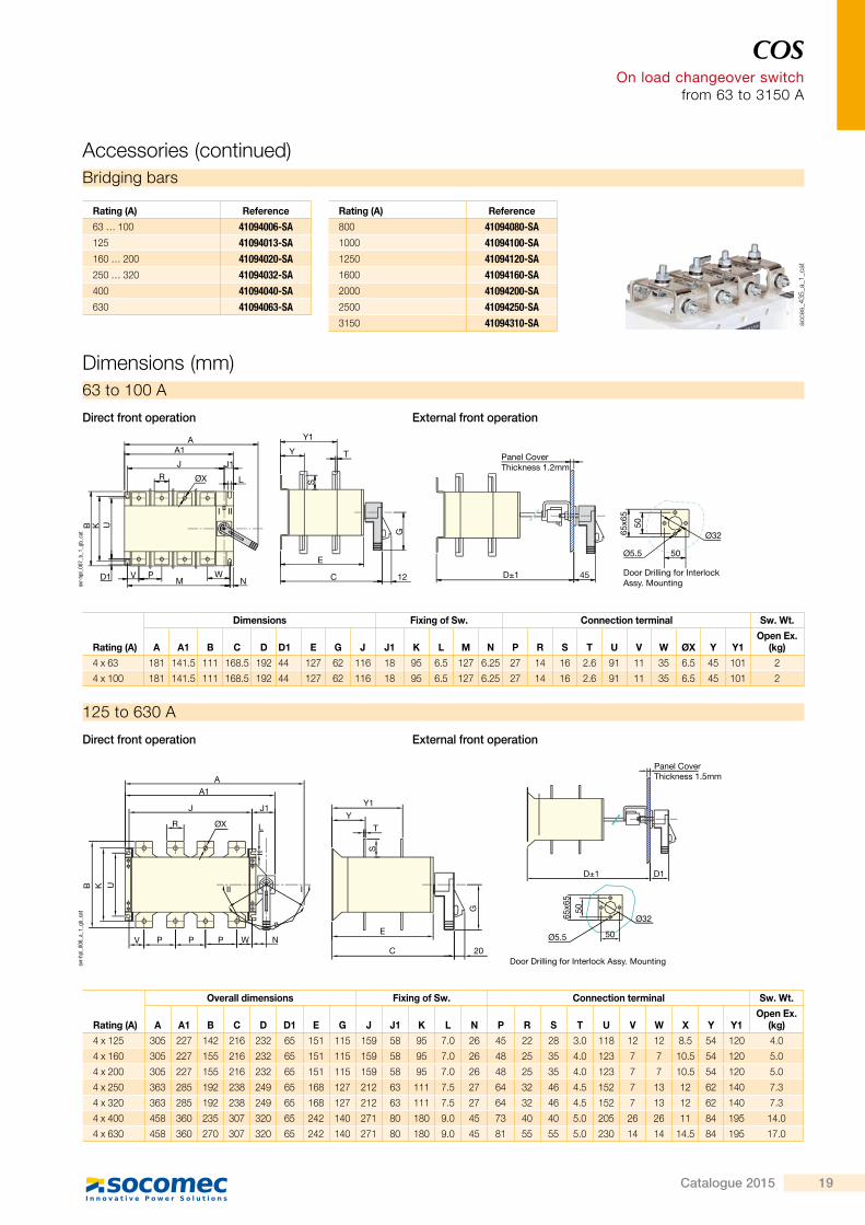
63 to 100 A
Dimensions (mm)
Rating (A)
Dimensions Fixing of Sw. Connection terminal Sw. Wt.
A A1 B C D D1 E G J J1 K L M N P R S T U V W ØX Y Y1Open Ex.
(kg)
4 x 63 181 141.5 111 168.5 192 44 127 62 116 18 95 6.5 127 6.25 27 14 16 2.6 91 11 35 6.5 45 101 2
4 x 100 181 141.5 111 168.5 192 44 127 62 116 18 95 6.5 127 6.25 27 14 16 2.6 91 11 35 6.5 45 101 2
AA1
J J1
LR ØX
B K U
D1 V PM
WN
E
C 12
G
Y1
Y T
S
D±1 45
Panel CoverThickness 1.2mm
65x6
5
50
Ø32
50Ø5.5
Door Drilling for InterlockAssy. Mounting
I II
svr-
hpl_
007_
b_1_
gb_c
at
Direct front operation External front operation
Door Drilling for Interlock Assy. Mounting
Panel CoverThickness 1.5mmA
A1
J J1
LR ØX
B K U
V P W N
III
PP
Y1
YT
S
E
C 20
G
D±1 D1
65x6
550
Ø32
50Ø5.5sv
r-hp
l_00
8_a_
1_gb
_cat
125 to 630 A
Direct front operation External front operation
Rating (A)
Overall dimensions Fixing of Sw. Connection terminal Sw. Wt.
A A1 B C D D1 E G J J1 K L N P R S T U V W X Y Y1Open Ex.
(kg)
4 x 125 305 227 142 216 232 65 151 115 159 58 95 7.0 26 45 22 28 3.0 118 12 12 8.5 54 120 4.0
4 x 160 305 227 155 216 232 65 151 115 159 58 95 7.0 26 48 25 35 4.0 123 7 7 10.5 54 120 5.0
4 x 200 305 227 155 216 232 65 151 115 159 58 95 7.0 26 48 25 35 4.0 123 7 7 10.5 54 120 5.0
4 x 250 363 285 192 238 249 65 168 127 212 63 111 7.5 27 64 32 46 4.5 152 7 13 12 62 140 7.3
4 x 320 363 285 192 238 249 65 168 127 212 63 111 7.5 27 64 32 46 4.5 152 7 13 12 62 140 7.3
4 x 400 458 360 235 307 320 65 242 140 271 80 180 9.0 45 73 40 40 5.0 205 26 26 11 84 195 14.0
4 x 630 458 360 270 307 320 65 242 140 271 80 180 9.0 45 81 55 55 5.0 230 14 14 14.5 84 195 17.0
Bridging bars
Accessories (continued)
Rating (A) Reference
63 … 100 41094006-SA125 41094013-SA160 … 200 41094020-SA250 … 320 41094032-SA400 41094040-SA630 41094063-SA
Rating (A) Reference
800 41094080-SA1000 41094100-SA1250 41094120-SA1600 41094160-SA2000 41094200-SA2500 41094250-SA3150 41094310-SA ac
ces_
435_
a_1_
cat
18 Catalogue 2015
COS On load changeover switch from 63 to 3150 A
COS from 630 to 3150 AReferences GC06304POI GC08004POI GC10004POI GC12504POI GC16004POI GC20004POI GC25004POI GC31504POI
Thermal current Ith (40°C) 630 A 800 A 1000 A 1250 A 1600 A 2000 A 2500 A 3150 A
Max. normal rating of fuses 630 800 1000 1250 1250 2 x 800 2 x 1000 2 x 1250
Insulation voltage Ui (V) 1000 1000 1000 1000 1000 1000 1000 1000
Dielectric strength (V) 50 Hz 1 mn. 8000 8000 8000 10000 10000 10000 10000 10000
Impulse voltage (kV) 12 12 12 12 12 12 12 12
Rated operational currents Ie (A) 415 VAC-AC 23A 630 800 1000 1000 1000 1250 1250 1250
500 VAC-AC 23A 315 630 1000 1000 1000 1000 1000 1000
260 VDC-DC 21A 630 800 1000 1250 1600 2000 2000 2000
260 VDC-DC 22A 500 800 1000 1250 1250 1250 1250 1250
260 VDC-DC 23A 500 800 1000 1250 1250 1250 1250 1250
440 VDC-DC 21A 500 630 1000 1250 1600 2000 2000 2000
440 VDC-DC 22A 500 800 1000 1250 1250 1250 1250 1250
440 VDC-DC 23A 500 800 1000 1000 1000 1000 1000 1000
Motor power (kW) 415V 415 VAC without pre-break auxiliary contact 220 450 560 560 560 710 710 710
500 VAC without pre-break auxiliary contact 220 450 560 560 710 710 710 710
690 VAC without pre-break auxiliary contact 150 185 400 400 475 475 750 750
415 VAC with pre-break auxiliary contact 355 450 560 710 710 900 1100 1155
500 VAC with pre-break auxiliary contact 355 550 710 710 900 900 1100 1100
690 VAC with pre-break auxiliary contact 295 475 600 600 750 750 900 900
Motor reactive 415 VAC (kVAR) 2 x 125 2 x 150 3 x 150 4 x 125 5 x 150 6 x 150 7 x 150 9 x 150
ProtectionShort-circuit current with fuses (kA rms) 80 80 80 80 80 80 80 80
Fuse rating 630 800 1000 1250 2 x 800 2 x 1000 2 x 1250 2 x 1250
Peak short-circuit making capacity (kA rms) 45 55 105 105 110 110 110 120
Admissible short time current 1 sec (kA rms) 13 26 50 50 50 50 50 55
Making & breaking characteristicsBreaking capacity (A rms) 415 VAC pf-0.35 5040 6400 8000 8000 8000 10000 10000 10000
Making capacity (A rms) 415 VAC pf-0.35 6300 8000 10000 10000 10000 12500 12500 12500
EnduranceMechanical No. of operations 5000 4000 4000 4000 3000 3000 2500 2500
Electrical No. of operations 1000 500 500 500 500 500 500 500
Operating force (Nm) 17 40 40 40 40 60 60 60
ConnectionMin. Cu cable/bus bar size (mm2) 40 x 5 x 2 50 x 5 x 2 60 x 5 x 2 80 x 5 x 2 100 x 5 x 2 100 x 5 x 3 100 x 5 x 4 100 x 10 x 3
Min. Al cable/bus bar size (mm2) 40 x 8 x 2 50 x 8 x 2 50 x 10 x 2 63 x 12 x 2 100 x 8 x 2 100 x 10 x 3 100 x 10 x 4
630 to 3150 A
Characteristics (continued)
Auxiliary contact Phase barrier
Accessories (continued)
1st auxiliary contactRating (A) Reference
63 … 100 26091020GI125 … 630 26091040GI800 … 3150 26091040GI
SmallRating (A) Reference
800…3150 G89B136GI
BigRating (A) Reference
800…1600 G89B143GI2000…3150 G89B491GI
2 nd auxiliary contactRating (A) Reference
63 … 100 26092020GI125 … 630 26092040GI800 … 3150 26092040GI
acce
s_42
0_a_
1_ca
tac
ces_
421_
a_1_
cat
acce
s_43
2_a_
1_ca
t
COSOn load changeover switch
from 63 to 3150 A
63 to 100 A
Dimensions (mm)
Rating (A)
Dimensions Fixing of Sw. Connection terminal Sw. Wt.
A A1 B C D D1 E G J J1 K L M N P R S T U V W ØX Y Y1Open Ex.
(kg)
4 x 63 181 141.5 111 168.5 192 44 127 62 116 18 95 6.5 127 6.25 27 14 16 2.6 91 11 35 6.5 45 101 2
4 x 100 181 141.5 111 168.5 192 44 127 62 116 18 95 6.5 127 6.25 27 14 16 2.6 91 11 35 6.5 45 101 2
AA1
J J1
LR ØX
B K U
D1 V PM
WN
E
C 12
G
Y1
Y T
S
D±1 45
Panel CoverThickness 1.2mm
65x6
5
50
Ø32
50Ø5.5
Door Drilling for InterlockAssy. Mounting
I II
svr-
hpl_
007_
b_1_
gb_c
at
Direct front operation External front operation
Door Drilling for Interlock Assy. Mounting
Panel CoverThickness 1.5mmA
A1
J J1
LR ØX
B K U
V P W N
III
PP
Y1
YT
S
E
C 20
G
D±1 D1
65x6
550
Ø32
50Ø5.5
svr-
hpl_
008_
a_1_
gb_c
at
125 to 630 A
Direct front operation External front operation
Rating (A)
Overall dimensions Fixing of Sw. Connection terminal Sw. Wt.
A A1 B C D D1 E G J J1 K L N P R S T U V W X Y Y1Open Ex.
(kg)
4 x 125 305 227 142 216 232 65 151 115 159 58 95 7.0 26 45 22 28 3.0 118 12 12 8.5 54 120 4.0
4 x 160 305 227 155 216 232 65 151 115 159 58 95 7.0 26 48 25 35 4.0 123 7 7 10.5 54 120 5.0
4 x 200 305 227 155 216 232 65 151 115 159 58 95 7.0 26 48 25 35 4.0 123 7 7 10.5 54 120 5.0
4 x 250 363 285 192 238 249 65 168 127 212 63 111 7.5 27 64 32 46 4.5 152 7 13 12 62 140 7.3
4 x 320 363 285 192 238 249 65 168 127 212 63 111 7.5 27 64 32 46 4.5 152 7 13 12 62 140 7.3
4 x 400 458 360 235 307 320 65 242 140 271 80 180 9.0 45 73 40 40 5.0 205 26 26 11 84 195 14.0
4 x 630 458 360 270 307 320 65 242 140 271 80 180 9.0 45 81 55 55 5.0 230 14 14 14.5 84 195 17.0
Bridging bars
Accessories (continued)
Rating (A) Reference
63 … 100 41094006-SA125 41094013-SA160 … 200 41094020-SA250 … 320 41094032-SA400 41094040-SA630 41094063-SA
Rating (A) Reference
800 41094080-SA1000 41094100-SA1250 41094120-SA1600 41094160-SA2000 41094200-SA2500 41094250-SA3150 41094310-SA ac
ces_
435_
a_1_
cat
19Catalogue 2015
COS On load changeover switch from 63 to 3150 A
Door Drilling for Interlock Assy. MountingHandle for 1000A-1600AHandle for 800A
Panel CoverThickness 1.5mm
AA1
J J1
LR ØX
B K U
V P W NPP
III
Y1Y
T
S
EC 20
G
D±1 81
65x6
5
50
Ø32
50Ø5.5
4xØ9 800A
Ø15
8.5 8.510
5033
33
1000/1250A16x11
19
25
25 171963
1600A
20
4xØ13
204080
2040
Connection terminal
svr-
hpl_
009_
a_1_
x_ca
t
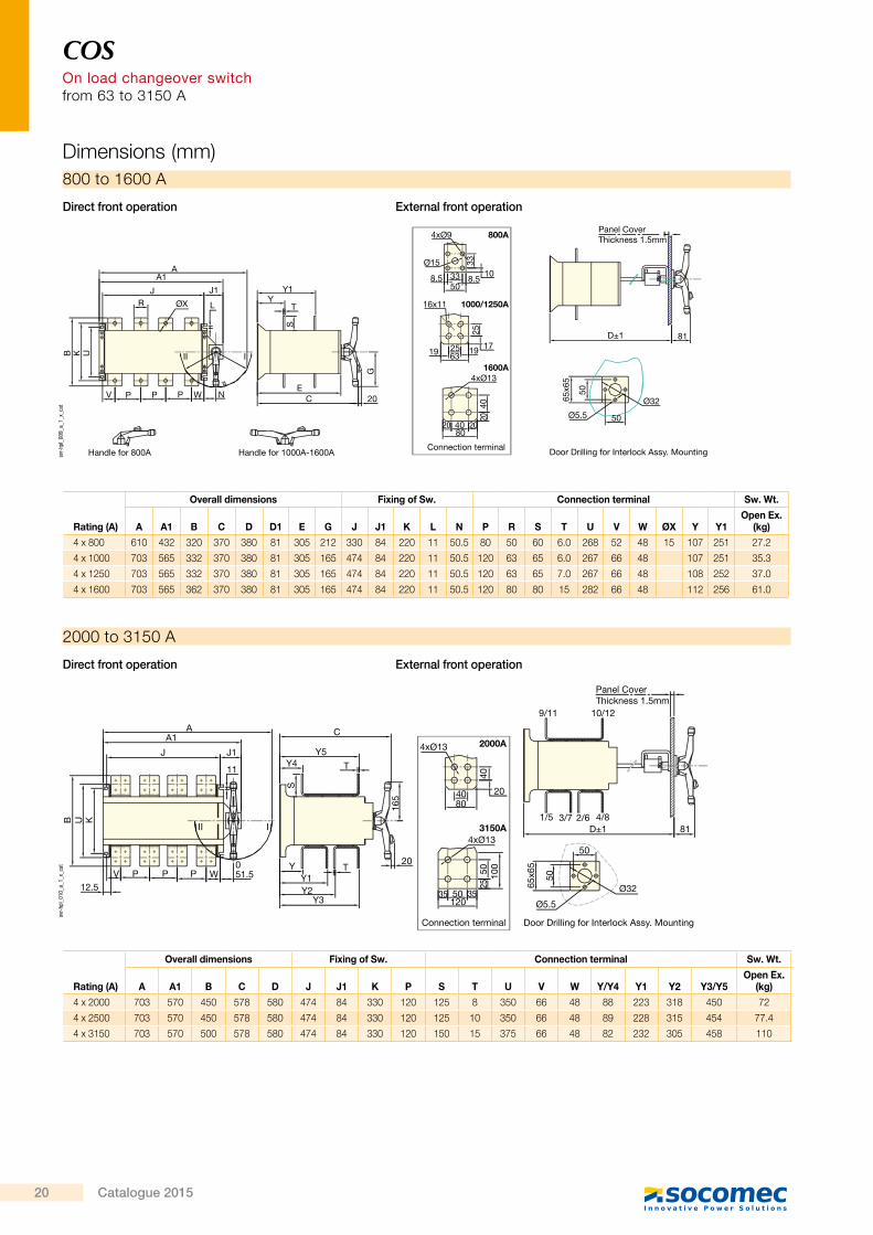
800 to 1600 A
Direct front operation External front operation
Rating (A)
Overall dimensions Fixing of Sw. Connection terminal Sw. Wt.
A A1 B C D D1 E G J J1 K L N P R S T U V W ØX Y Y1Open Ex.
(kg)
4 x 800 610 432 320 370 380 81 305 212 330 84 220 11 50.5 80 50 60 6.0 268 52 48 15 107 251 27.2
4 x 1000 703 565 332 370 380 81 305 165 474 84 220 11 50.5 120 63 65 6.0 267 66 48 107 251 35.3
4 x 1250 703 565 332 370 380 81 305 165 474 84 220 11 50.5 120 63 65 7.0 267 66 48 108 252 37.0
4 x 1600 703 565 362 370 380 81 305 165 474 84 220 11 50.5 120 80 80 15 282 66 48 112 256 61.0
Door Drilling for Interlock Assy. Mounting
Panel CoverThickness 1.5mm
Connection terminal
AA1
J J1
11
II I
B KU
V P WPP051.5
12.5
C
Y5Y4 T
S
Y TY1Y2
Y3
20
165
4xØ13 2000A
8040 20
40
3150A4xØ13
35 3550120
2550 10
0
9/11 10/12
1/5 3/7 2/6 4/8D±1 81
Ø32
50
50
65x6
5
Ø5.5
svr-
hpl_
010_
a_1_
x_ca
t
2000 to 3150 A
Direct front operation External front operation
Rating (A)
Overall dimensions Fixing of Sw. Connection terminal Sw. Wt.
A A1 B C D J J1 K P S T U V W Y/Y4 Y1 Y2 Y3/Y5Open Ex.
(kg)
4 x 2000 703 570 450 578 580 474 84 330 120 125 8 350 66 48 88 223 318 450 72
4 x 2500 703 570 450 578 580 474 84 330 120 125 10 350 66 48 89 228 315 454 77.4
4 x 3150 703 570 500 578 580 474 84 330 120 150 15 375 66 48 82 232 305 458 110
Dimensions (mm)
Cha
ngeo
ver
swit
ches
H
W X
LY
References & dimensions
coff_
379_
a_1_
x_ca
t
Enclosed COSOn load changeover switchfrom 63 to 3150 A
Function
Advantages
Manually operated sheet steel enclosed changeover switches provide changeover, source inversion or switching under load between two low voltage power circuits, as well as their safety isolation. The enclosure provides protection against contact with live parts as well as environmental factors such as dust, water and other hazards. • On load manual changeover between 2 sources
• Emergency breaking • Selection between two loads • Safe isolation of downstream loads for maintenance purpose
On load operation (AC22/AC23)Manual changeover enclosures are designed for operation on load and are able to make and break mixed/inductive loads (utilisation categories AC22/AC23).Robust products have been designed for severe industrial conditions with chemical, pollution or atmospheric corrosion risks.
General Characteristics
• Adapted to environments subject to chemical, dust, contamination and atmospheric corrosion risks.
• Black Handle padlockable in 0/I/II position • CRCA sheet (Door 1.2 mm, Body 1.6 mm) • Colour shade: RAL 7035 coating of epoxy polyester powder 70 micron
• 2 external earthing points on each side • Wall mounted with 4 bolts • Door locking system allows opening of door only in off position
• Incoming & outgoing easily interchangeable at site
• Removable plate top & bottom • Door with solid hinges
> Safe and easy to use > Stable positions > Large connection capabilities for direct aluminium cable connection
Strong points
Rating (A) Reference L (mm) W (mm) X (mm) Y (mm) H (mm)63 GCD00634PEI 250 200 160 280 212
100 GCD01004PEI 250 200 160 280 212
125 GCD01254PEI 355 285 245 385 254
160 GC01604PEI 355 285 245 385 254
200 GC02004PEI 355 285 245 385 254
250 GC02504PEI 425 375 335 455 271
320 GC03204PEI 425 375 335 455 271
400 GC04004PEI 510 475 422 560 342
630 GC06304PEI 510 475 422 560 342
800 GC08004PEI 555 470 422 605 404
1000 GC10004PEI 800 655 600 825 423
1250 GC12504PEI 800 655 600 825 423
1600 GC16004PEI 800 655 600 825 423
2000 GC20004PEI 800 750 685 825 632
2500 GC25004PEI 800 750 685 825 632
3150 GC31504PEI 800 750 685 825 632
> IS/IEC 60947-3
Conformity to standards
> Standby power
The solution for
coff_
459_
a
coff_
458_
a
20 Catalogue 2015