cost-effective separation technologies …infohouse.p2ric.org/ref/23/22090.pdfseparation...
TRANSCRIPT

GG37GUIDE
COST-EFFECTIVE SEPARATION TECHNOLOGIESFOR MINIMISING WASTESAND EFFLUENTS

© Crown copyright. First printed December 1996. This material may be freely reproduced except for sale or advertising purposes.
Paper made from 100% post-consumer waste.
COST-EFFECTIVESEPARATION TECHNOLOGIESFOR MINIMISING WASTESAND EFFLUENTS
This Guide was produced by the
Environmental Technology Best Practice Programme
Prepared with assistance from: AEA Technology plc

Many industrial processes generate effluent streams that contain a mixture of substances. To reducethe cost of processing these streams, operators can remove the substances that they contain usinga range of separation technologies.
Using separation technologies as part of the production process - for instance as a method ofcleaning continuously recirculating process water - can prove more cost-effective than using alarger effluent treatment plant. It is an approach that usually requires less energy and: is lesscapital-intensive in terms of plant; allows the recovery and re-use of individual substances, manyof which may be valuable; retains water of an appropriate purity within the process so that it canbe recycled.
This Good Practice Guide describes proven technologies and techniques for the cost-effectiveseparation of four types of dissolved substance from liquid streams:
■ heavy metals;
■ anions (metals and non-metals);
■ organics;
■ water in organics.
It also considers the separation of gases and liquids.
This Guide is intended to help companies decide whether separation technology can be used tominimise their waste streams and, if so, to indicate the most appropriate technologies available.
For each of the technologies examined, this Guide first discusses the general principles of thetechnology, its typical applications, main advantages and disadvantages and approximate costs. Itthen considers issues such as the technology’s efficiency and limitations, scale of operation, the mainoutputs and any ancillary plant required.
The choice of technology in any situation will depend on the specific nature of the streams involved.However, this Guide offers guidelines as to the likely suitability of each technology for certain tasks,basing its conclusions on that technology’s general characteristics.
In some cases, a technology is applicable to the removal of a whole range of substances. Reverseosmosis and nanofiltration, two membrane separation technologies, can, for instance, be used toremove dissolved heavy metals, anions, organics and water in organics. The same is true forevaporation. In other instances, a technology has a much narrower application. Adsorption and airstripping are only used in the separation of dissolved organics, for example. Some technologies fallbetween these two extremes. The main application of the various electrical technologies, forinstance, is in the removal of dissolved heavy metals and anions, and the same is true for ionexchange and precipitation techniques.
In the separation of gases from liquids, demisters and electrostatic precipitation techniques are usedto remove mists in gas streams, while defoaming technologies and separation vessels are usedwhere bubbles of gas occur in a liquid and also for treating two-phase mixtures.
The information provided represents an important starting point in the specification and selectionof an appropriate separation technology. More detailed information should then be sought fromequipment suppliers.
S U M M A R Y

Section Page
1 Introduction 1
2 Selecting the appropriate technology 2
3 Separation of dissolved substances from liquids 6
3.1 Adsorption 6
3.2 Ion exchange 9
3.3 Precipitation 11
3.4 Membrane technologies 13
3.5 Electrical technologies 19
3.6 Evaporation 25
3.7 Distillation 27
3.8 Dissolved air flotation 28
3.9 Air/steam stripping 30
4 Separation of gases from liquids 34
4.1 Separation vessels 34
4.2 Defoaming technologies 37
4.3 Demisting technologies 39
4.4 Electrostatic precipitation 41
Appendix Contacts for products and services 45
C O N T E N T S


Many industrial processes generate effluent streams that contain a mixture of substances. To reducethe cost of processing these streams, operators can remove the substances that they contain usinga range of separation technologies.
Using separation technologies as part of the production process - for instance as a method ofcleaning continuously recirculating process water - can prove more cost-effective than using alarger effluent treatment plant. It is an approach that usually requires less energy and: is lesscapital-intensive in terms of plant; allows the recovery and re-use of individual substances, manyof which may be valuable; retains water of an appropriate purity within the process so that it canbe recycled.
Substances can be present in a process stream in particulate or dissolved form. Particulates are easilyremoved, whereas the separation of truly dissolved materials is more difficult. This Guide describesthe various technologies that can be used for separating the following dissolved substances fromliquid streams:
■ dissolved organics, whether specific solvents or materials generating a high chemical oxygendemand (COD);
■ soluble metals (either ionic or complexed);
■ anions such as chloride or nitrate;
■ colour;
■ pesticides;
■ dissolved gases in liquids.
In Section 2 of this Guide, Tables 1 and 2 list potential technologies and the main categories ofsubstance they are capable of separating. Table 3 summarises the general characteristics of eachtechnology. You should use these tables for the initial screening process.
Once you have generated a short list of potentially suitable technologies, you should consult therelevant parts of Sections 3 and 4 of this Guide for more detailed information. This information isprovided to a standard format and considers issues such as the general principles of the technology,typical applications, main advantages and disadvantages, approximate costs, efficiency andlimitations, scale of operation, outputs and any ancillary plant required.
The Appendix contains a list of contacts for products and services relating to each technology. Thislist is by no means exhaustive, but will help you to contact recognised organisations and supplycompanies.
1
I N T R O D U C T I O N1
section
1

Before selecting a particular technology, you should assess the type of separation required andeliminate those technologies that would be unsuitable for treating the liquid stream specified. Thefollowing flow diagram (Fig 1) and Tables 1 - 3 will help you to do this more quickly.
Complete the flow diagram as fully as you can. It is designed to take you through the selectionprocess on a step-by-step basis.
Box 1 - Identify which effluent stream you wish to treat.
Box 2 - Identify the characteristics of the effluent stream.
Box 3 - Assess in detail any other factors that are likely to influence the technology selectionprocess.
Only when Boxes 2 and 3 are complete should you consider in more detail the individualtechnologies that might be appropriate to your situation.
Use Tables 1 and 2 initially to eliminate unsuitable technologies.
Then, by comparing the characteristics of the feed stream (Box 2) and other constraints (Box 3)with the main performance limitations listed in Table 3, the more probable technology choices canbe prioritised, before moving on to review more detailed information in later sections.
2
section
2
S E L E C T I N G T H E A P P R O P R I AT ET E C H N O L O G Y
2

Fig 1 Flow diagram: selecting the appropriate technology
3
section
2
4
5
3
2
1
Min Max
Organic content
Temperature
pH
Flow rate
Volume
Concentration of solids
Concentration ofdissolved substances 1
2
3
4
5
6
1 4
2 5
3
6
7
1st
2nd
3rd
Number the following from 1 - 7 according to priority.
Priority
Space/footprint
Substance recovery
Capital cost
Operating cost
Compliance withdischarge consents
Final effluent quality
Batch or continuous
Other
Identify which effluent stream you wish to treat.
Using Tables 1 and 2, select those technologies that are capable of removing the substances you identi-fied in Box 2.
Use Table 3 to assess these technologies in terms of the characteristics of your effluent stream (Box 2) and the factors influencing your choice of tech-nology (Box 3), and generate a short list.
Look up each of the short listed technologies in Sections 3 and/or 4, and establish the suitability of each for your particular effluent stream. Rank your choices.
Seek advice from appropriate sup-plier. A selection of contacts is given in the Appendix.
Establish the stream's main charac-teristics and variability. Identify any dissolved substances present.
Assess the factors that will influence your choice of technology.
1 6
2 7
3 8
4 9
5 10

4
section
2
Table 1 Matrix of technologies vs substances for removal - liquids
Table 2 Matrix of technologies vs substances for removal - gases
Substances for removal
Dissolved heavy metals
Monovalent ions (eg Ag+) ✓ ✓ ✓ ✓ ✓ ✓ ✓ ✓
Multivalent ions (eg Ni2+) ✓ ✓ ✓ ✓ ✓ ✓ ✓ ✓ ✓
Complexed metals (eg Cu + EDTA) ✓ ✓ ✓ ✓ ✓ ✓ ✓ ✓
Dissolved anions
Non-metals (eg Cl, SO42-) ✓ ✓ ✓ ✓ ✓ ✓ ✓
Metals (eg Cr2O72-) ✓ ✓ ✓ ✓ ✓ ✓ ✓ ✓ ✓
Dissolved organics
Solvents ✓ ✓ ✓ ✓ ✓
Macromolecules eg proteins ✓ ✓ ✓ ✓ ✓ ✓ ✓
General chemical oxygen demand (COD) ✓ ✓ ✓ ✓ ✓ ✓ ✓
Colour ✓ ✓ ✓ ✓ ✓ ✓
Pesticides ✓ ✓ ✓
Dissolved water in organics ✓ ✓ ✓ ✓ ✓
Ad
sorp
tio
n
Ion
exc
han
ge
Prec
ipit
atio
n
Mem
bra
ne
tech
no
log
ies
Rev
erse
osm
osi
s
Nan
ofi
ltra
tio
n
Ult
rafi
ltra
tio
n
Perv
apo
rati
on
Elec
tric
al t
ech
no
log
ies
Dir
ect
elec
tric
al p
roce
ssin
g
Elec
tro
coag
ula
tio
n
Elec
tro
dia
lysi
s
Elec
tro
chem
ical
ion
exc
han
ge
Evap
ora
tio
n
Dis
tilla
tio
n
Dis
solv
ed a
ir f
lota
tio
n
Air
/ste
am s
trip
pin
g
Technology type
Substances for removal
Mixtures of liquids and gases
Mist in gas stream ✓ ✓ ✓ ✓
Two-phase mixtures ✓ ✓ ✓
Bubbles of gas in liquid ✓ ✓ ✓
Sep
arat
ion
ves
sels
Gra
vity
sep
arat
or
Cyc
lon
ic s
epar
atio
n
Def
oam
ing
pro
cess
es
Dem
iste
rs
Kn
itte
d m
esh
Wav
e p
late
Fib
re m
ist
elim
inat
or
Elec
tro
stat
ic p
reci
pit
atio
n
Technology type

5 section
2Technology type Substances for which this technology is most effective
Adsorption 6 L M 1 L+ H+ A ** ** BC Y High molecular weight, low solubility organics, eg solvents
Ion exchange 9 H M 1 H+ H+ A ** *** BC Y Low molecular weight ionics (acids and metals)
Precipitation 11 L L 3 H+ H+ A * ** SB N Metals and anions, eg phosphate
Reverse osmosis and nanofiltration 13 M M 2 L+ L+ A *** ** BC Y Low molecular weight solutes, chemical oxygen demand (COD)
Ultrafiltration 16 M L 2 M+ M+ A/(O) ** ** BC Y Macromolecules and colloids, eg paints and proteins
Pervaporation 18 H M 2 N/A M+ O/(A) ** * BC N/A Dewatering solvents
Direct electrical processing 19 M M 1 H+ H+ A * * BC Y Heavy metals, eg cadmium, medium to high concentration
Electrocoagulation 21 M M 2 H+ H+ A * * BC N Organics, particulates, emulsions
Electrodialysis 22 H M 2 H+ M+ A ** ** BC N Acid recovery, salt concentration
Electrochemical ion exchange 24 H M 2 H+ M+ A ** * BC N Heavy metals, low to medium concentration
Evaporation 25 H H 2 H+ H+ O/A * *** BC N Concentration of dissolved solutes, eg salts
Distillation 27 H H 2 H+ H+ O/A * *** BC N Volatile organics, eg trichloroethylene, solvent recovery
Dissolved air flotation 28 M L 3 H+ H+ A * * C N Organics, particulates, emulsions
Air/steam stripping 30 L L 1 N/A H+ A * N/A BC N Volatile organics, eg trichloroethylene, solvent recovery
Pag
e n
um
ber
s
Cap
ital
co
st
Op
erat
ing
co
st
Foo
tpri
nt
pH
ran
ge
Tem
per
atu
re r
ang
e
Co
nti
nu
ou
s p
has
e
Pre-
trea
tmen
t n
eed
ed
Seco
nd
ary
was
te t
reat
men
t
Bat
ch o
r co
nti
nu
ou
s
Bac
k-u
p u
nit
s re
qu
ired
Comparative performance parameters
Key:ABBCCHLMNOSBY1,2,3
L+
M+
H+
******
AqueousBatchBatch and continuousContinuousHighLowMediumNoOrganicSemi-batchYesSmall, medium and large sizes respectivelyWill tolerate relatively small pH and temperature rangesWill tolerate moderate pH and temperature rangesWill tolerate broad pH and temperature rangesMinor treatment requiredModerate treatment requiredExtensive treatment required
Table 3 Matrix of technologies vs operating parameters

3.1 ADSORPTION
The technology
Adsorption is a commonly used physical and/or chemical process in which a substance becomesbound or attached to a surface and is thereby removed from a liquid stream. It is particularly suitablefor separating a stream that contains dissolved organics at levels of <10 mg/litre with low levels ofother contaminants.
Activated carbon is the most commonly used adsorbent and is particularly effective in the removalof soluble organics. It is an amorphous form of graphite with a porous structure and is used in bothgranular form (particle size 1 - 3 mm) and powdered form (particle size <100 µm). The powderedform is usually added to the feed stream, then filtered out downstream. The granular material ismost commonly used for water and waste-water treatment and is typically employed in a downflowfixed-bed pressure system, as shown in Fig 2.
The feed stream is introduced into the pressure vessel above the carbon bed and gradually flowsdownwards. Treated water is removed at the vessel base. The pore structure of the carbon graduallybecomes irreversibly saturated with water and adsorbed substances, and the bed eventually has tobe replaced.
Typical applications
Adsorption is typically used for removing moisture dissolved in gasoline, decolourising petroleumproducts and aqueous sugar solutions, and removing objectionable taste, colour and odour. Table 4gives examples of other industrial applications.
6
section
3
Fig 2 Adsorption using the downflow fixed-bed pressure system
S E PA R AT I O N O F D I S S O LV E DS U B S TA N C E S F R O M L I Q U I D S
3

Type of industry Typical impurity removed Plant size (m3/day)
Textiles and dyestuffs. Total organic carbon (TOC), colour, dyes. 200 - 6 000
Oil refinery and petrochemical. Chemical oxygen demand (COD), biological 8 000 - 15 000oxygen demand (BOD).
Detergents, resins, chemicals. TOC, COD, xylene, alcohols, phenolics, resin 60 - 10 000 intermediates, resorcinol, nitrated aromatics, polyols.
Herbicides and insecticides. Chlorophenols, cresol. 500 - 2 000
Pharmaceuticals. Phenol. 50 - 100
Explosives. Nitrated phenol. 20 - 100
Table 4 Examples of industrial applications for adsorption separation systems
Advantages and disadvantages
Advantages Disadvantages
Very effective at removing organics. Generates waste carbon.
Systems are automated. Operating costs may be high.
Wide range of substances can be treated.
Approximate costs
Table 5 gives typical capital costs for system purchase (excluding installation). The two smallersystems would be skid-mounted, pre-assembled units. The large system would require additionalfield assembly.
Using an adsorption process can improve product quality and reduce the costs of waste disposal.Companies can achieve an acceptable payback period when investing in this technology.
Bed capacity Typical max. series Capital cost
(kg carbon) flow rate (m3/hour) (including carbon)
1 000 14 30 000
5 000 60 75 000
10 000 120 110 000
Table 5 Adsorption separation systems: typical capital costs
Efficiency and limitations
Adsorption can reduce total residual organic concentrations to <1 µg/litre. However, wherecontamination levels of >10 mg/litre are present, the adsorber bed material would need to bechanged frequently. In these circumstances, it is more economical to employ a pre-treatmentprocess, such as air-stripping (see Section 3.9).
Adsorption efficiency also varies with the molecular weight and solubility of the compoundsinvolved. Table 6 indicates that the compounds most readily adsorbed using activated carbon arethose with a high molecular weight and a low solubility in water.
Readily adsorbed Poorly adsorbed
Chlorinated compounds (eg trichloroethylene) Alcohols
Aromatic compounds (eg toluene) Aldehydes
Polynuclear aromatics
High molecular weight amines
Table 6 Adsorption potential of specified compounds
7
section
3

The downflow fixed-bed pressure system that is commonly used for industrial waste-watertreatment by adsorption can handle large feed-stream flows, and a vessel with a diameter of 2.5 mcan treat flows of up to 120 m3/hour. However, because most adsorber beds are prefabricated priorto delivery, transportation limitations set an upper limit on the size of the adsorber bed and thereforeon feed-stream throughput.
Scale of operation
A typical adsorber unit normally contains about 10 tonnes of carbon on a dry-weight basis. Thespent carbon removed from such a unit, however, is about twice as heavy as the dry carbon (about20 tonnes). This brings it close to the practical limit for road transport. Where a process requireslarger-scale adsorption facilities, these are usually met using multiple units. Small units are alsoavailable for irregular or low throughput adsorption duties. These contain perhaps 50 kg of carbonand are capable of processing 2 m3/hour.
Outputs
Apart from the treated water, the main output of adsorption is spent carbon. This can be landfilled(costing perhaps £50/tonne), incinerated as a solid waste, or reactivated. Reactivation can beachieved by heating the spent carbon to temperatures of up to 1 000°C in a controlled atmosphereusing a rotary kiln or multiple-hearth furnace suitably equipped with off-gas treatment. Reactivationcosts may be between £1 000 and £2 000/tonne.
Ancillary plant needed
The range of ancillary plant needed will depend on the nature of the feed stream, including thedegree of contamination and the pH level. For example, pre-treatment is usually necessary toremove suspended solids, oils and greases, particularly where suspended solids are present inconcentrations greater than 50 mg/litre. Although the adsorption bed can effectively remove thesematerials, their presence may give rise to problems of head loss, and fouling and plugging of theadsorber. Chemical clarification, air flotation and filtration are common pre-treatment processes, andpH adjustment is sometimes used to enhance adsorption efficiency.
8
section
3
Industry Example 1
Devonport Management Ltd washes the hulls of ships. This generates waste waterthat contains tri-butyl tin (TBT) compounds (from the anti-fouling paints used toprotect the hulls). TBT is a Red List substance, and the effluent concentrationsgenerated by the Company can exceed the Environmental Quality Standard of lessthan 2 ng/litre.
Devonport Management Ltd uses adsorption onto granular activated carbon toreduce TBT levels, processing 15 m3/hour and discharging the treated stream into ariver. With this technology, operating costs for treating 4 000 m3 of waste watercontaining less than 150 ng/litre of TBT were £17 000/year, including carbon,maintenance, analysis and monitoring, labour and regulatory authorisation. Theequivalent cost of disposal by tanker to a waste site was £74 000/year. The net annualsaving using adsorption was £57 000. A payback period of about three years will beachieved, excluding savings in increased operational flexibility.

3.2 ION EXCHANGE
(See also Section 3.5.4 Electrochemical Ion Exchange)
The technology
Ion exchange is a method of separation that depends on the interchange of ions between a solutionand the surface of the ion exchange material. The technology is not normally suitable for highlycontaminated solutions. Furthermore, it may require the installation of tanks for storing the feedstreams during off-line regeneration, or cleaning, of the ion exchanger.
Ion exchange is reversible. There is no permanent change to the ion exchange material and, afterregeneration, this can be re-used.
There are several types of ion exchange material, including:
■ natural minerals such as zeolites (based on alumino-silicates), hydrous oxides or phosphates;
■ organic polymers with attached functional groups, which can be specific for cations(sulphonic or carboxylic functional groups) or anions (based on amine groups).
Water softening is one example of ion exchange. The exchanger is able to exchange sodium forcalcium ions, thus removing the hard component of the water. However, because the ion exchangeris not permanently altered by this process, it is possible, subsequently, to reverse the reaction. Thecalcium-loaded resin is regenerated using a sodium chloride solution (the regenerant solution) tobring it back to the sodium form ready for another cycle of operation. The concentrated salt solution(NaCl) used for regeneration has a much smaller volume than the original feed stream, and thecalcium ions present in this solution after regeneration provide a more concentrated by-product thatis ready for use, disposal or further treatment.
Typical applications
Ion exchange is applied to the treatment of spent process solutions and waste waters in a widerange of industries. Typical examples include the decontamination of various rinse waters generatedin the metal finishing industry. Table 7 lists potential applications.
Metal industry applications Non-metallic applications
Cyanide plating baths. Photographic processing effluent.
Nickel, copper, tin or zinc rinses. Chloralkali brines.
Aluminium anodising rinse waters. Textile and tannery effluents.
Pigment manufacture.
Table 7 Potential applications of ion exchange separation
Advantages and disadvantages
Advantages Disadvantages
Effective decontamination - very low finalconcentrations are possible.
Possible recovery of valuable species.
Water recovery may also be possible, for example from washing processes in the metalfinishing industry.
No sludges produced - metal ions removeddirectly, not by precipitation.
9
section
3
Efficiency depends on the feed stream.
A secondary waste may be produced from theregeneration process.
Stability of ion exchangers - these deteriorate with time,both mechanically and chemically.
Costs may be higher than for other technologies.

Approximate costs
Capital costs depend greatly on the nature of the feed stream. For a packed height of 1 m, an off-the-shelf column of 1 m diameter may cost about £60 000 (vessel, valves and resin only). Costs riseby about £20 000 for each 0.5 m increase in column diameter.
Synthetic polymer resins, unless they are being used to recover a high-value metal such as gold, aretoo expensive to replace once fully loaded. The principal operating cost is therefore regeneration,which is highly dependent on the type of resin employed, the feed-stream quality and the operatingarrangement. Under certain circumstances, the consumption of regenerant solution can be high,and this increases operating costs appreciably, particularly if the used regenerant solution needssubsequent treatment. However, the cost benefits in terms of reduced waste disposal costs,reduced raw material costs and improved product quality mean that an acceptable payback periodcan be achieved.
Efficiency and limitations
The efficiency of substance removal from the feed stream is dependent on four factors:
■ feed-stream quality - a high level of suspended solids can cause excessive pressure drops inthe resin bed, and the resin can also be fouled by the irreversible adsorption of large organicmolecules;
■ the initial concentration of the substance being removed;
■ the frequency of ion exchanger regeneration;
■ ageing - the resin can suffer a loss in performance as a result of either chemical degradationor physical change.
Loss of performance may also occur because of the precipitation of insoluble compounds such ascalcium sulphate.
Ion exchange equipment should be carefully monitored after installation to determine the conditionsrequired for optimum efficiency. Your equipment supplier will also be able to provide appropriateinformation in this respect.
Scale of operation
This is usually expressed in terms of the number of bed volumes (BV) of feed stream that can betreated in unit time; this varies according to the process. The bed volume is the actual (bulk) volumeof the ion exchange material in the vessel. As a guide, a normal bed depth in fixed-column operationis about 1 - 1.5 m, and the largest units can reach 4 m in diameter. Maximum loading of the ionexchanger can be 40 - 50 BV/hour, whereas regeneration cycles tend to operate at a rate of4 - 5 BV/hour. A bed of 1 m depth and 2 m diameter can process about 160 m3/hour.
Outputs
Apart from the treated stream leaving the ion exchange column, the main output is the regenerantsolution that has been used to remove metal ions or other substances from the exchanger surface,thereby restoring it to its original condition. The level of contamination of the used solution may behigh. As a result it, in turn, will require further treatment.
Ancillary plant needed
Ancillary plant may be required for the following processes:
■ pre-filtration of feed stream and/or removal of large organic species to ensure that the ionexchange bed does not become fouled;
■ temperature control;
■ additional process vessels to cope with on-line/off-line regeneration of the ion exchangematerial.
10
section
3

Electricity is also needed to pump the feed stream and the regenerant solution through the ionexchange bed.
3.3 PRECIPITATION
The technology
The addition of a chemical agent to cause a dissolved substance to precipitate out of solution is asimple and relatively cheap method of separation. However, there are four basic stages in theprocess - pH adjustment, flocculation, clarification and filtration (Fig 3) - all requiring tanks of asuitable capacity which, in turn, may take up a large amount of space.
Separation by precipitation is widely used in industry to treat metal-bearing effluents. Most of themetal ions exhibit decreasing solubility with increasing pH. Adding an alkaline agent thus promotesthe precipitation of a metal hydroxide sludge. The most commonly used agents are lime, causticsoda or sulphide-based materials.
Other species, such as anions, can also be treated by precipitation. Furthermore, under certaincircumstances, dissolved organics (as chemical oxygen demand), oils, greases and surfactants can beremoved by chemical treatment using reagents such as lime, aluminium sulphate or ferric chloride.
Typical applications
Typical applications for precipitation are shown in Table 8.
Industry Principal pollutants Chemical processes used
Food processing. Biological oxygen demand Emulsion cracking, flocculation.(BOD), fats, solids.
Inorganic chemicals. Acids, alkalis, metals. pH adjustment, flocculation.
Mining and minerals. Metals, acids, alkalis. pH adjustment, flocculation.
Surface treatment Cyanides, metals, Redox, pH adjustment,(including metal finishing). surfactants, greases. flocculation.
Wool processing. BOD, greases, solids. Emulsion cracking, pH adjustment,flocculation.
Table 8 Typical applications for precipitation
11
section
3
Fig 3 Separation by precipitation

Advantages and disadvantages
Advantages Disadvantages
Technology is well established.
Offers a low capital cost route for treatingmetal-bearing streams.
Approximate costs
The design of neutralisation and precipitation plant is highly specific to each application and issensitive to certain factors that will affect costs:
■ the generation of sludge, which incurs additional handling and disposal costs;
■ the production of by-product gases (such as hydrogen sulphide) from the acidification ofstreams containing certain solutes; such gases must be safely handled and treated.
A rough guide to the capital cost of a neutralisation plant can be obtained using the followingformula:
C = 90 + 16Q0.6
where C represents the capital cost in £ for a plant throughput of Q m3/hour.
Reagents make up the largest fraction of operating costs. They are supplied in 1 m3 intermediatebulk containers (IBCs), and approximate prices are shown in Table 9.
Reagent Concentration (%) Price (£/m3)
Hydrochloric acid 36 250 - 300
Sulphuric acid 96 350 - 400
Sodium hydroxide (caustic soda) 47 370 - 420
Calcium hydroxide (lime slurry) 18 100 - 150
Ferric chloride 60 600 - 700
Table 9 Reagent costs
Where the treated stream and the separated solids can be recovered for re-use or recycling, theprecipitation method provides a means for reducing waste disposal costs and raw material costs fora minimal capital outlay.
Efficiency and limitations
Separation by precipitation is suited to feed streams with high flow rates. However, the finalconcentration of metals in the treated stream depends on the nature of the feed stream and, inparticular, on whether complexing agents such as ethylene diamine tetra-acetic acid (EDTA) arepresent.
When using reagents such as lime or caustic soda, a hydroxide precipitate forms. The solubility ofthese hydroxide species varies with pH for each metal. Table 10 indicates minimum theoreticalsolubility and the pH at which it occurs1. This information thus sets the limits of performance forthe process.
12
section
3
1 The Hydrolysis of Cations, C F Baes and R E Mesmer, Robert E Krieger Publishing Co Inc, Florida 1986.
Optimum pH for mixed metal streams is uncertain- thus performance is variable.
Sludge is generated as secondary waste.
Complexed metals not easily treated.

Metal ion Minimum solubility (mg/litre) pH of minimum solubility
Cd2+ 0.05 11.4
Cr3+ 0.26 8.6
Cu2+ 3.2 x 10⁻⁵ 9.7
Hg2+ 80 >4
Ni2+ 5.9 x 10⁻⁴ 10.2
Pb2+ 83 10.9
Zn2+ 0.2 9.8
Table 10 Minimum solubility and associated pH for metal hydroxides
Scale of operation
This process can be operated to treat very small quantities, ie a few m3/day, or very large quantities,ie hundreds of m3/day. The appropriate size of balance and settling tank should be chosen to suitthe volume of the feed stream that requires treatment.
Outputs
All precipitation processes produce a secondary sludge that requires further treatment both toseparate it from the purified stream and to dewater it so that it is acceptable for disposal. Wheremetal concentrations are high, the volumes of sludge generated are large, and the costs of disposalmay, in some instances, limit the use of precipitation as a separation process.
Ancillary plant needed
The ancillary plant required for precipitation typically includes reactors for pH adjustment andmaturation, thickeners, and dewatering equipment (usually a filter and slurry pumps). Equipment forpH metering is also important for effective monitoring and control.
3.4 MEMBRANE TECHNOLOGIES
Introduction
A membrane allows specific types of substance to pass through while retaining others. Differenttypes of membrane retain different sorts of dissolved substance or solute. Reverse osmosismembranes, for example, will prevent low molecular weight salts from passing through, whereasultrafiltration membranes will allow those salts to pass through but will retain larger molecules suchas proteins. Membranes can therefore be used to separate certain dissolved substances fromsolvents (Fig 4). The different types and their applications are discussed separately in the followingsub-sections.
There are a number of process designs for membrane systems. The nature of the separation processdictates which is the most appropriate. Fig 5 illustrates the feed-and-bleed design, which is oftenused to concentrate products or to treat effluents.
3.4.1 Reverse osmosis and nanofiltration
The technology
Reverse osmosis and nanofiltration both generate a purified solvent (most often water) from astream containing solutes. The feed stream passes under pressure to a membrane module whichcontains the membranes in the form of tubes, hollow fibres or flat sheets in a plate-and-frame orspiral-wound formation. Solvent passes through the membrane to form the permeate, leaving astream that is more concentrated in solute (the retentate).
13
section
3

Reverse osmosis and nanofiltration differ in the level of separation obtained. Reverse osmosis retainseven small molecules and ionic species, whereas nanofiltration membranes retain molecules with amolecular weight of more than about 150 (such as sugars) and divalent ions such as calcium,magnesium or sulphate.
Typical applications
Typical uses of reverse osmosis and nanofiltration include:
■ the separation of ionic species from effluents such as the rinse waters from plating processes;
■ the removal of general chemical oxygen demand (COD) or solvents from effluent streams;
■ the generation of pure water for high purity use or plant recycling;
■ the removal of colour (iron and humic substances) from drinking water to satisfy EC qualitydirectives.
Advantages and disadvantages
Advantages Disadvantages
Compact and modular. Certain substances may cause performance loss.
Low risk. Generate secondary waste of spent cleaning reagents.
Easily automated.
14
section
3
Fig 5 Feed-and-bleed design of membrane separation system
Fig 4 Separation using membranes

Approximate costs
Plant cost varies with design throughput. One method of estimating this cost is to evaluate themembrane area required for a certain duty, then multiply the cost of the membrane elements andmodules by between about 5 and 8 to provide an approximate total plant cost.
Examples:
■ Municipal water desalination plant: 45 000 m3/day: cost approximately £10 million.
■ Removal of COD from effluent: 40 m3/day: cost approximately £100 000.
Operating costs are particularly significant for pumping power and cleaning chemicals. In both casescosts are generally proportional to plant size.
The cost of installing and operating membrane systems can be more than paid for by reduced wastedisposal costs and raw material costs where treated streams are re-used.
Efficiency and limitations
There are two measures of efficiency:
■ the production of a high and sustainable permeate flow;
■ the retention of solute by the membrane.
Permeate flows are measured in terms of flux, which is the flow rate of permeate per unit area ofmembrane surface (generally measured in litres/m2/hour). This may be in the 20 - 60 litres/m2/hourrange for effluent applications, and will be higher for clean duties. Progressive surface fouling limitsthis performance, giving rise to the need for periodic cleaning in situ.
The retention of solute depends on solute type, the membrane material chosen and the pressureapplied (Tables 11 and 12).
The main process limitations relate to the concentrations of solute that can be handled. For amembrane system to operate, the pressure applied to the feed stream must overcome the stream’sown osmotic pressure before a permeate can be obtained. For example, a stream containing 6%sodium chloride has an osmotic pressure of about 25 bar, thus needing an applied pressure of atleast 25 bar to generate permeate. Highly concentrated solutions may therefore require pressuresthat are not compatible with process equipment (usually rated at 70 bar) or that are not economical.
There are differences in this respect between reverse osmosis and nanofiltration. Nanofiltration doesnot retain very small molecules or monovalent ions (such as sodium or chloride). It can thereforeprocess streams with higher overall solute concentrations and operates at lower pressures (typically15 - 30 bar compared with 30 - 70 bar for reverse osmosis).
Scale of operation
Reverse osmosis and nanofiltration are modular processes that use arrays of membrane modules toachieve the desired plant performance. There is virtually no limit to the capacity of these membranesystems. Large desalination plants produce tens of thousands of cubic metres of potable water eachday whereas, for small applications, single modules can give product flows of as little as 1 m3/day.
15
section
3
Percentage retention
Sodium Magnesium chloride sulphate
Reverse osmosis 99+ 99+
Nanofiltration 20 80
Table 11 Reverse osmosis and nanofiltration:
retention of solute according to solute type
Pressure (bar)
20 30 40
% retention of sodium 98 98.5 99
chloride by reverse osmosis
Table 12 Reverse osmosis: retention of solute
according to pressure

Outputs
There are three main streams and wastes from reverse osmosis and nanofiltration:
■ permeate product with low solute content, often 80 - 95% of the feed stream volume;
■ a low-volume concentrate stream containing the retained solutes;
■ spent cleaning reagents containing substances such as detergents or chelating agents, whichcan be acidic or alkaline depending on the stream being processed.
Ancillary plant needed
The main item of ancillary plant required is for pre-filtering the feed stream prior to reverse osmosisor nanofiltration. It is normally necessary to screen out solids larger than about 10 µm, unless themembrane modules used have large flow channels (ie tubular systems).
3.4.2 Ultrafiltration
The technology
Ultrafiltration is a fine filtration process that can filter out macromolecular substances such asproteins or very fine colloidal material. The feed stream passes tangentially over a membranesurface. Applied pressure drives the solvent through tiny pores, with the membrane retainingdissolved molecules with a molecular weight in the 3 000 - 100 000 range, depending on the typeof membrane used.
Ultrafiltration systems comprise arrays of membrane modules which contain the membranes in theform of tubes, hollow fibres or flat sheets in a plate-and-frame or spiral-wound formation.
Typical applications
Typical applications for ultrafiltration include:
■ the separation of biological products such as proteins from fermentation broths;
■ the removal of haze from beverages such as beer or cider;
■ the recovery of sizing agents in the textile industry;
■ the recovery and recycling of electrophoretic paints in the automotive industry.
16
section
3
Industry Example 2
Contract Chemicals in Liverpool has a waste stream from a still that is used toconcentrate one of its final products, an aliphatic compound. Originally, this streamwas neutralised with acid and then discharged as trade effluent. Following tests andtrials, a 320 m2 membrane plant was built and commissioned in May 1994. This usesreverse osmosis to recover the aliphatic compound from the effluent stream, allowingit to be recycled back into the process.
The plant is designed to handle a feed stream with a 2% aliphatic content, atemperature of 20°C, and a pH of 11.5. It can operate at a rate of 2 300 litres/hour for21 hours/day, giving a permeate with an aliphatic content of less than 0.12% and aflow rate of more than 1 760 litres/hour. The plant has proved very successful. Itoperates for 5 000 hours/year, achieving a 75 - 80% reduction in volume of the originalfeed stream. Because it has reduced the chemical oxygen demand of the finaleffluent, it has significantly reduced effluent treatment and disposal costs.
The plant cost £160 000 to purchase and install. Operating costs, including labour,cleaning materials, utilities and routine maintenance (minimal) are £65 000/year.

Advantages and disadvantages
Advantages Disadvantages
Compact and modular. Certain substances may cause performance loss.
Low risk. Generates secondary waste of spent cleaning reagents.
Easily automated.
Approximate costs
The total plant cost for ultrafiltration applications can be estimated by multiplying the cost of themembrane units needed for a particular duty by about 4 - 5. This is lower than the cost of reverseosmosis and nanofiltration plant (see Section 3.4.1).
The cost of membrane modules variesgreatly. Table 13 shows approximatevalues for larger scale applications.
The cost of installing and operating suchmembrane systems can be more than paidfor by reductions in costs of waste disposaland raw materials when treated streamsare recovered and re-used.
Efficiency and limitations
Measures of permeate flow and solute retention are the key performance parameters. Permeateflows are measured in terms of flux, which is the flow rate of permeate per unit area of membranesurface (generally measured in litres/m2/hour). Flux does not usually vary linearly with appliedpressure, but often reaches a limiting value at between 3 and 5 bar. Depending on the application,flux can be between 30 and 100 litres/m2/hour.
Unlike reverse osmosis, osmotic pressure is not a limiting factor for ultrafiltration as the dissolvedsubstances involved are much larger. As a result, ultrafiltration can give effective separation ofmacromolecules over a range of concentrations.
Scale of operation
As with reverse osmosis and nanofiltration, ultrafiltration is a modular process that can beengineered to produce large or small flows. At the large scale, the limits are financial rather thantechnical.
Outputs
The main product of ultrafiltration can be either the permeate or the retentate, depending on theapplication. The permeate consists of purified solvent containing dissolved solutes of a smallermolecular weight than can be removed by the membrane. The retentate will contain thosesubstances that do not pass through the membrane. Spent membrane cleaning reagents are theusual secondary wastes.
Ancillary plant needed
The ancillary plant required depends in part on the type of membrane used. For example, membranemodules with narrow flow channels (such as hollow-fibre or spiral-wound modules) require pre-filtration to screen out solids larger than about 10 µm.
The required pumping power is much lower for ultrafiltration than for reverse osmosis ornanofiltration as the pressures used are mostly in the 1 - 5 bar range.
17
section
3
Type of module Cost (£/m2)
Spiral wound (polymeric membrane) 50 - 100
Hollow fibre (polymeric membrane) 100 - 200
Flat sheet (polymeric membrane) 700 - 1 000
Tubular (polymeric membrane) 300 - 900
Tubular (ceramic membrane) 1 000 - 2 000
Table 13 Ultrafiltration: cost of membrane modules

Cleaning chemicals are generally needed, although some tubular and hollow-fibre systems arecleaned by back-flushing the permeate through the membrane in the reverse direction to removesurface deposits.
3.4.3 Pervaporation
The technology
Pervaporation is a membrane separation process that can separate water from organic solvents andvice versa. The feed stream passes over the surface of a special, non-porous membrane that allowsone component (usually water) to permeate through the membrane. The other side of themembrane is kept under vacuum. This vacuum creates the driving force that vaporises thepermeating component. Heat is also required.
Typical applications
Pervaporation is typically used to remove solvents from water streams, for example, methyl ethylketone can be recovered from printing ink using pervaporation.
Advantages and disadvantages
Advantages Disadvantages
Lower energy requirements than distillation.
Easily automated.
Modular equipment, smaller than distillation systems.
Approximate costs
There are no pervaporation plants of significant scale operating in the UK at present. Accurate costinformation is, therefore, not available. For more information, consult the principal supplier of suchequipment (see Appendix).
Efficiency and limitations
Given a good choice of equipment that iswell suited to a particular process, theefficiency of pervaporation can be high. Aprocess for separating water anddichloroethane (DCE) in a feed streamgenerated the data shown in Table 141.
The main variable influencing separationefficiency is the choice of membranematerial for the application. Temperatureusually has no effect.
An important limitation is the energy cost of the process; this is proportional to the flow rate ofpermeate removed. Pervaporation is therefore usually applied to the de-watering of organic solventsin which the water content is low (10 - 20%), thereby minimising the operating costs.
Scale of operation
As with other membrane technologies, pervaporation is modular and can be engineered to a giventhroughput. Installations for flows of up to 150 m3/day are operational.
18
section
3
1 Filtration and Separation, November 1993, 620-622.
Still needs energy input.
Works economically only at low concentrations of thematerial to be removed (usually water).
Contamination in feed stream may influenceperformance.
Stream Main Concentration component of DCE
Feed Water 8 600 ppmv
Product stream 1 Water 5 ppmv
Product stream 2 DCE 99.7%
Table 14 Results of using pervaporation to separate water
and dichloroethane (DCE)
Outputs
The feed stream emerging from the process is liquid, whereas the product stream is a vapour, whichis usually then condensed.
Ancillary plant needed
Pervaporation requires ancillary plant to provide:
■ electrical power;
■ a vacuum;
■ heat (perhaps from a low-grade source) for pre-heating the feed stream;
■ condensation.
3.5 ELECTRICAL TECHNOLOGIES
Introduction
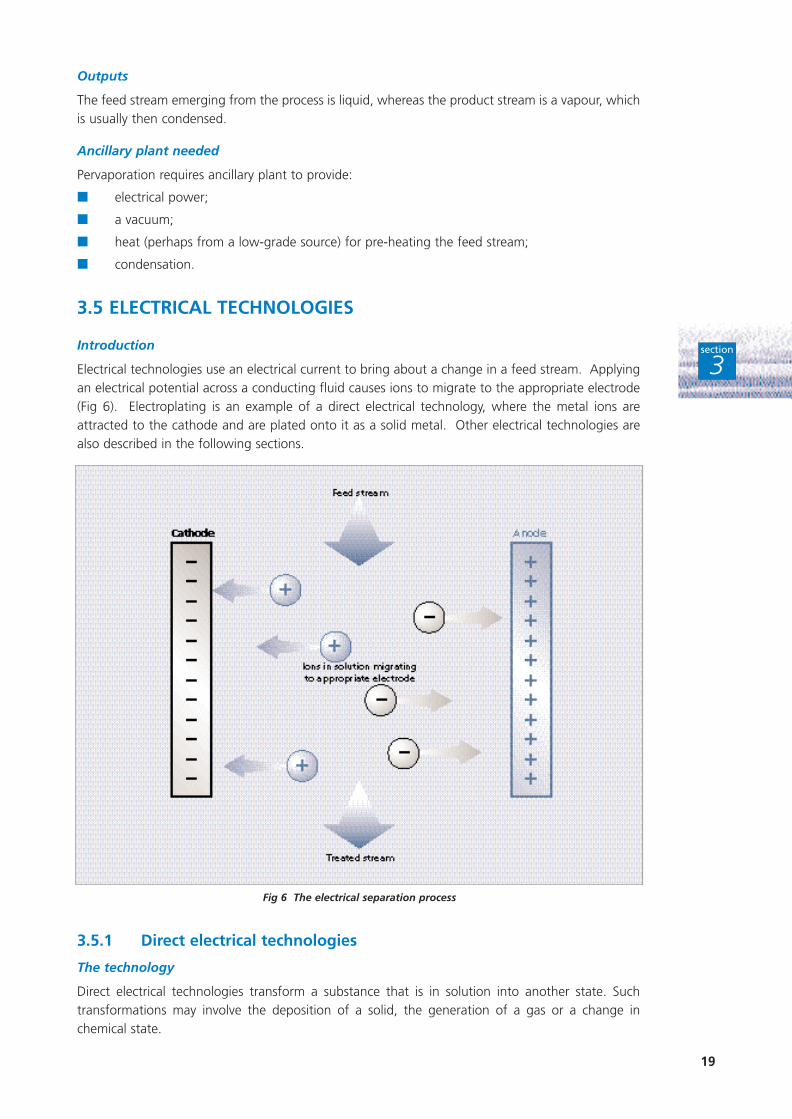
Electrical technologies use an electrical current to bring about a change in a feed stream. Applyingan electrical potential across a conducting fluid causes ions to migrate to the appropriate electrode(Fig 6). Electroplating is an example of a direct electrical technology, where the metal ions areattracted to the cathode and are plated onto it as a solid metal. Other electrical technologies arealso described in the following sections.
3.5.1 Direct electrical technologies
The technology
Direct electrical technologies transform a substance that is in solution into another state. Suchtransformations may involve the deposition of a solid, the generation of a gas or a change inchemical state.
19
section
3
Fig 6 The electrical separation process

When metal ions are removed, the solid formed is usually the metal itself or a metal oxide. Theelectrochemical reaction takes place at an electrode (usually solid) which may take any one of anumber of forms (for example, sheet, particle, fibre or mesh).
Typical applications
Direct electrical technologies are often used to recover metals such as copper, nickel and chromiumfrom waste streams.
Advantages and disadvantages
Advantages Disadvantages
Can be highly efficient.
Easily adaptable to different volumes and flow rates.
Simple and remote control.
Wide range of target concentrations.
Waste often in a recyclable form.
Approximate costs
An indication of costs can be derived from the following example. A company attached a 50 cmself-contained unit to an alkaline cadmium static rinse tank. The unit has a typical flow rate of 25litres/minute and is capable of removing 11 g of cadmium per hour. The cadmium concentration inthe rinse tank is maintained between 10 - 100 mg/litre. The system cost approximately £5 000, andelectrical operating costs are 1.2 pence/m3.
Recovery of valuable metals in this way can provide excellent cost benefits and short paybackperiods.
Efficiency and limitations
Under normal conditions, electrochemical cells are able to reduce the metal component of a feedstream down to concentrations of about 10 mg/litre. However, feed stream conditions such as pH,temperature, and the presence of other salts or organic substances influence the efficiency of theremoval process. A high concentration of ions in the feed stream is desirable to produce highcurrent density in the cell.
To achieve a high current efficiency (and therefore low operating costs) the rate of ion transport tothe electrode must be high. This is achieved by using either high surface area electrodes (eg packedbeds or reticulated beds) or forced convection (eg rotating cylinder), or both.
High levels of efficiency can have significant cost benefits to the companies involved. One companyusing direct electrical technologies to recover copper, nickel and chromium worth £11 000/yearachieves a recovery efficiency of more than 99% of the metal in solution. Current efficiency is upto 95%. Two sizes of cell are used in this instance: the P size uses 45 amperes (A)/5 volts (V) torecover 3 kg of copper per week; the S size uses 400 A/5 V to recover 35 kg of nickel per week.The use of this technology saves the company £28 000/year overall.
A second company focuses on copper recovery, achieving savings of £2/kg copper comparedwith chemical treatment. The system cost £40 000, and energy consumption is 1.4 kWh/kgcopper recovered.
20
section
3
Efficiency can be dependent on feed stream.
Does not operate efficiently at very lowconcentrations.
Suitable for a limited number of target substances(must be electroactive).
Feed stream must be conducting.

Scale of operation
Operating and capital costs normally limit the scale of operation.
The operating costs are dictated by the current and voltage required. The current required fortreating a metal-bearing feed stream will be proportional to the flow rate, the metal concentrationof the stream and the number of electrons required for the reduction; it will be inverselyproportional to the current efficiency - the ratio of the theoretical charge required to remove ionsfrom solution to the charge actually used.
Plant size (and therefore capital cost) will depend on the current density, the total current requiredto achieve the process, and the cell geometry. Plants can thus be sized to treat any flow rate.
Outputs
The main outputs are the metal itself and the treated feed stream. The metal occurs either on anelectrode or as a powder. It is also possible to generate a concentrated solution by stripping coatedelectrodes. The treated stream is simply the original feed stream with the ions removed.
Ancillary plant needed
Direct electrical technologies require:
■ an electrical supply (dc);
■ plant for pre-filtration of the feed stream;
■ cooling systems.
3.5.2 Electrocoagulation
The technology
In electrocoagulation, a sacrificial anode (usually iron or aluminium) dissolves in the feed stream. Inthe presence of suitable anions (usually hydroxide) this produces an insoluble floc whichencapsulates or adsorbs the impurity ions (usually other metal ions) and causes them to precipitateout.
Typical applications
A typical application is the removal of fluoride from solution using aluminium electrodes to generatethe alumina that subsequently adsorbs the fluoride.
Advantages and disadvantages
Advantages Disadvantages
Effective and controllable addition of a Electrodes are sacrificial and thus require chemical additive. replacement.
High precipitant concentrations local to the electrode Electrodes can be poisoned.can improve the efficiency of the precipitation.
Approximate costs
A pilot plant for treating a 0.6 m3/hour fluoride stream, reducing the concentration from 40 mg/litreto 5 mg/litre, costs about £25 000. Aluminium electrodes are used to generate precipitant.
Where the treated stream and the separated solids can be recovered for re-use or recycling,electrocoagulation provides a means of reducing waste disposal and raw material costs for aminimal capital outlay.
21
section
3
Efficiency and limitations
Efficiency depends on the chemistry of the precipitation and adsorption reactions with the impuritysubstance. Various factors influence these processes, including the choice of precipitant, othersubstances in the feed stream, and pH.
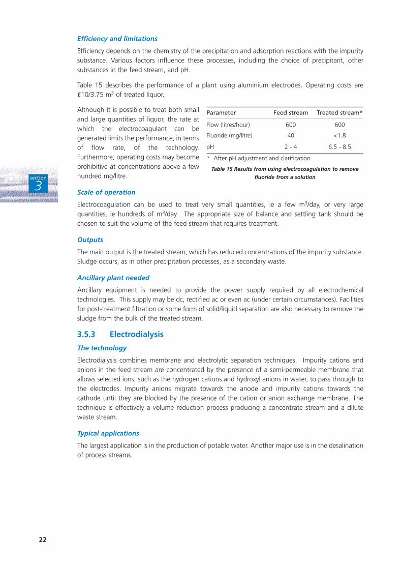
Table 15 describes the performance of a plant using aluminium electrodes. Operating costs are£10/3.75 m3 of treated liquor.
Although it is possible to treat both smalland large quantities of liquor, the rate atwhich the electrocoagulant can begenerated limits the performance, in termsof flow rate, of the technology.Furthermore, operating costs may becomeprohibitive at concentrations above a fewhundred mg/litre.
Scale of operation
Electrocoagulation can be used to treat very small quantities, ie a few m3/day, or very largequantities, ie hundreds of m3/day. The appropriate size of balance and settling tank should bechosen to suit the volume of the feed stream that requires treatment.
Outputs
The main output is the treated stream, which has reduced concentrations of the impurity substance.Sludge occurs, as in other precipitation processes, as a secondary waste.
Ancillary plant needed
Ancillary equipment is needed to provide the power supply required by all electrochemicaltechnologies. This supply may be dc, rectified ac or even ac (under certain circumstances). Facilitiesfor post-treatment filtration or some form of solid/liquid separation are also necessary to remove thesludge from the bulk of the treated stream.
3.5.3 Electrodialysis
The technology
Electrodialysis combines membrane and electrolytic separation techniques. Impurity cations andanions in the feed stream are concentrated by the presence of a semi-permeable membrane thatallows selected ions, such as the hydrogen cations and hydroxyl anions in water, to pass through tothe electrodes. Impurity anions migrate towards the anode and impurity cations towards thecathode until they are blocked by the presence of the cation or anion exchange membrane. Thetechnique is effectively a volume reduction process producing a concentrate stream and a dilutewaste stream.
Typical applications
The largest application is in the production of potable water. Another major use is in the desalinationof process streams.
22
section
3
Parameter Feed stream Treated stream*
Flow (litres/hour) 600 600
Fluoride (mg/litre) 40 <1.8
pH 2 - 4 6.5 - 8.5
* After pH adjustment and clarification
Table 15 Results from using electrocoagulation to remove
fluoride from a solution

Advantages and disadvantages
Advantages Disadvantages
Simple technique.
Can regenerate useful chemicals.
Current efficiency usually high (>75%).
Approximate costs
Capital costs for the treatment of brackish water (1 600 mg/litre salinity) to produce potable waterat a rate of 1 800 m3/hour are about £15 - 20 million. Operating costs are about 20 pence/m3.
Where treated streams are recovered and re-used, electrodialysis can reduce raw material and wastedisposal costs.
Efficiency and limitations
The efficiency of electrodialysis is equivalent to the ratio of the charge required to remove the ionsfrom the solution to the actual charge applied by the power source. Current efficiencies are oftenin excess of 75%, although this value falls significantly if the feed stream is acidic or if it containsionic substances at concentrations greater than 50 g/litre.
Electrodialysis can be used to treat low and high volumes of waste, but the current density andmembrane area will define the rate of liquor treatment for a fixed concentration. The amount ofelectrical energy consumed will be proportional to the concentration and volume of the feed stream.
Feed streams with an impurity concentration of less than about 0.3 g/litre are rarely treated since,because of resistance effects, it is not possible to pass high currents through them. The upperconcentration limit of the treated stream is usually about 150 g/litre.
Scale of operation
Flow rates of up to about 1 800 m3/hour are appropriate for electrodialysis. The technique can alsobe used to treat much smaller volumes of water at the pilot-plant scale.
Outputs
There are two main outputs: the desalinated feed stream from which most ions have been removedapart from the solvent (water); and a secondary concentrated form of the feed stream. If thesolubility of any substance is exceeded during the process, a precipitate can form. This can beinhibited by adding complexing agents.
Ancillary plant needed
Electrodialysis requires plant for:
■ the pre-filtration of solids;
■ chlorine removal (as the membranes are sensitive to chlorine);
■ a supply of dc power.
23
section
3
Streams must be conductive.
Is only a roughing technique. High decontaminationlevels cannot be achieved.
Not very selective.
Pre-filtration required.
Care needed to limit precipitation.

3.5.4 Electrochemical Ion Exchange
The technology
Electrochemical ion exchange (EIX) is an advanced ion exchange technology (see also Section 3.2 IonExchange) in which an electrical driving force enhances both the adsorption and regenerationreactions at the ion exchanger. EIX is a separation technology, and can be regarded as a crossbetween electrodialysis and conventional ion exchange. However, unlike the latter, regenerantchemicals are not usually required. This reduces the volume of waste requiring treatment.
Typical applications
EIX has been used to treat a waste stream at a pressurised water reactor in Belgium. Small-scaleunits have also been designed for treating radioactive waste from hospitals.
Advantages and disadvantages
Advantages Disadvantages
Minimal requirement for regenerant chemicals.
Higher utilisation of available exchange capacity than conventional ion exchange.
More tolerant to organic and particulate fouling than electrodialysis or ion exchange.
Technique can be selective to particular ions.
Approximate costs
The 200 litre/hour unit for treating the pressurised water reactor waste stream in Belgium cost£40 000 to construct and install. Operating costs were about 5 pence/m3 and were dominated byelectricity charges.
Where treated streams are recovered and re-used, EIX can reduce the cost of raw materials andwaste disposal.
Efficiency and limitations
A typical value for current efficiency is about 50%. Current efficiency is the ratio of charge requiredto remove ions from solution to the actual charge applied. This is influenced by:
■ the presence of any interfering substance in the stream, which may include other ions;
■ pH levels;
■ organic substances capable of fouling the column.
As the concentration of the target substance increases, so the pH of the treated liquor will decrease(for cation removal). This reduces current efficiency.
In terms of effectiveness, for the Belgian application described above, EIX reduced the radioactivityin the waste by 93%.
The resistance of the system limits the concentration of the impurity treated, since the currentrequired for the treatment is proportional to the impurity ion concentration. The maximumconcentration normally treated is in the 1.5 - 2 g/litre range.
Scale of operation
Only small or pilot-scale plants have been installed to date. The maximum flow rate achieved hasbeen of the order of 1 m3/hour. The design is modular and therefore commercial considerationsdefine the limit on the treatment rate. Very small-scale units have been produced and tested onradioactive hospital wastes at flow rates of only a few ml/hour. The size of the plant will increasewith total flow rate.
24
section
3Current efficiency can be low because of the presence of interfering substances.
Requires filtration if solids >10 mg/litre.
Still under development - only small to medium-scaleunits on site.

Outputs
The main output is the treated stream - the feed stream with the target substances removed. Thisremoval may cause a change in pH levels. The secondary wastes generated can take two forms:either concentrated solutions (acidic, basic or neutral) or plated metals.
Ancillary plant needed
Ancillary plant is needed to allow:
■ the provision of a dc power source;
■ pre-treatment of feed by filtration to <10 mg/litre solids;
■ the removal of oxidising species such as chlorine.
3.6 EVAPORATION
The technology
Evaporation uses a heat input, sometimes coupled with a reduction in pressure, to vaporise andremove one or more components from a liquid feed stream. These components can then becondensed to form a cleaner stream. If only one component of the original feed stream is volatile,the stream formed by condensation is pure. Evaporation reduces the volume of the original feedstream and concentrates non-volatile substances that were dissolved in it (Fig 7).
Typical applications
Common applications for evaporation include:
■ the dewatering of salt streams (especially for the production of potable water);
■ the concentration of saline effluents prior to disposal, further processing or recycling;
■ the recovery of salts from brines and saline waters using solar evaporation (mainly confinedto countries with a hotter climate than that experienced in the UK).
Evaporative technologies are not often used for effluent applications.
Advantages and disadvantages
Advantages Disadvantages
Can achieve high concentration factors.
Is an effective technology for the final concentration of some streams.
25
section
3
Fig 7 Separation by evaporation
Heat input can be high for large streams.
Heat exchange surfaces can be easily fouled.
Unsuitable for heat-sensitive materials.

Approximate costs
Because of the diversity of evaporator designs, little detailed information is available on system costs.For a vertical-tube, falling-film evaporator, capital and installation costs are dependent onthroughput. A unit treating about 30 m3/hour costs around £1 million. Costs for larger units areapproximately proportional to throughput.
Where evaporation is designed to recover a solid product, an appropriate crystalliser must beinstalled. This can greatly increase capital costs.
Where treated streams are recovered and re-used, waste disposal and raw material costs can begreatly reduced.
Efficiency and limitations
Several factors affect the efficiency of evaporation, including the energy required to vaporise thesolvent and the degree of fouling encountered on the heat exchange surfaces.
Performance is governed by the composition of the feed stream. Evaporation is a suitable separationtechnology where only one component of the feed stream, usually the solvent, is volatile. Thequantity of solvent evaporated is thus proportional to the heat input to the process.
Evaporator performance is rated on the basis of steam economy - mass of solvent evaporated perunit mass of steam used. Heat is used in the evaporation process to raise the initial temperature ofthe feed stream to boiling point and vaporise the solvent. Reducing the temperature at which thefeed solution boils reduces the heat input requirements, and re-using the vaporised solvent withinthe process also improves steam economy. These are the principles of the multiple-stage evaporator:the vapour from one stage provides the heat input to the next stage, where boiling takes place ata lower temperature and pressure.
Employing a thermo-compression evaporator further enhances performance. The vapour stream iscompressed so that it will condense at a temperature high enough to allow its use as the heatingmedium in the same evaporator.
Scale of operation
The energy costs can be prohibitive if using evaporation for more than tens of m3/day.
Outputs
Two streams emerge from the evaporation process:
■ the residual liquid feed stream, which will have an increased concentration of largely non-volatile dissolved substances;
■ a solvent vapour stream that may be condensed.
Evaporation produces no secondary wastes.
Ancillary plant needed
Ancillary plant is needed to generate the heat source that drives the evaporation process. Vacuumsystems may also be installed where improved performance justifies the extra expense. Although acondenser usually removes the vapour from the last stage of an evaporator, non-condensable gasesmay also be present in the vapour and may need to be removed, usually by venting. Some pre-treatment facilities may also be required to remove particulate or other fouling matter present in thefeed stream before it is processed.
When an evaporator is used to generate a crystalline product, there are several possible methods ofconcentrating and removing the salt from the system. One is to provide settling space in theevaporator itself. For larger throughputs, a salt trap may be used.
26
section
3

27
section
3
3.7 DISTILLATION
The technology
Distillation exploits the difference in volatility between the components of a liquid mixture. When aliquid stream of two or more components boils, the concentration of each component in the vapouris in proportion to its volatility. The remaining liquid is therefore rich in the less volatile substances,while the vapour product contains higher amounts of more volatile material. This generatesprogressive separation.
The equipment used for distillation will depend on the feed streams involved. A single-stage flashunit can be used for streams containing substances of greatly differing volatilities. A column isnecessary for more difficult separations that often involve multi-component mixtures. The generalarrangement of a distillation column is shown in Fig 8.
Typical applications
Distillation is typically used for:
■ the separation of solvent mixtures for recovery and re-use;
■ the removal of large fractions of volatile organic compounds from aqueous feed streams.
Advantages and disadvantages
Advantages Disadvantages
Separation generally very reliable.
Technology well established.
Performance easily predicted.
High flow streams can be handled.
Fig 8 Separation by distillation
High energy input.
Some separations require the addition of azeotropebreakers.
Vacuum may be required.

Approximate costs
The cost of distillation facilities varies greatly, depending on process conditions, separationspecifications and construction materials. It is not possible to give generic costs.
Where the treated streams are recovered and re-used, distillation can greatly help to reduce wastedisposal and raw material costs.
Efficiency and limitations
In theory, distillation is appropriate whatever the efficiency of separation required. In practice,several factors determine the level of efficiency that can be achieved, notably the relative volatilityof the components, the height of the distillation column, and the temperature and pressure usedfor the separation process.
Very demanding separations require a high energy input and tall columns. Examples includesituations where:
■ a high purity of one component is required;
■ volatilities of the components are similar.
The height of the unit is also influenced by the choice of internal column components, such aspacking. Increasing the column diameter allows the processing of high flow rates.
However, there are two potentially limiting factors that must be considered in any distillationapplication:
■ the formation of any immiscible phases in the process;
■ the presence of an azeotrope in the system.
This last phenomenon describes the situation when the vapour phase generated has the samecomposition as the liquid, making further separation of the components impossible. An example ofa common azeotrope is a water-ethanol mixture of about 96% by weight ethanol. Addingcomponents such as benzene can break the azeotrope. Alternatively, a technology such aspervaporation may be considered.
Scale of operation
The cost of energy can be prohibitive if treating more than tens of m3/day. The potential value ofthe recovered streams should be balanced against the energy requirements of the process.
Outputs
Feed streams are usually liquid, although they can enter the unit as vapour. The output streams willprobably be liquid, although the top vapour product will have to be condensed. These streams willprobably be hot unless the process uses vacuum distillation.
Ancillary plant needed
The application of heating and cooling at the bottom and top of the column respectively means thatheat exchangers and energy sources/sinks must be part of the process. Waste heat or cooling watercan be re-used where appropriate.
3.8 DISSOLVED AIR FLOTATION
The technology
Dissolved air flotation (DAF) is a clarification technology that removes suspended matter by inducedflotation using very fine air bubbles. Induced flotation occurs when suspended matter forms acomposite with air bubbles and floats to the top of a liquid. DAF can operate at higher rates thancommon gravity sedimentation equipment and therefore requires less space.
28
section
3

29
section
3
Dissolved substances can also be removed by DAF if appropriate coagulants are added to encourageadsorption at the air/water interfaces.
DAF is carried out in tanks about 1.5 m deep, with a water path of perhaps 4 m. The feed stream,treated with flocculating agents, enters the inlet mixing chamber, as does the recycle, which is nearlysaturated with air. The stream then passes to the flotation zone, where the solids migrate to thesurface and are mechanically skimmed (Fig 9).
Typical applications
Typical applications of DAF include:
■ the recovery of fibres from paper mill effluents;
■ the separation of flocculated and non-flocculated oils in waste water from refineries, airports,steelworks and foundries;
■ the thickening of sludges from biological waste-water treatment.
Advantages and disadvantages
Advantages Disadvantages
Volume of clarification is less than in gravity-based settling plant.
Quality of the clarified water is excellent.
Unaffected by changes of flow rate and temperature.
Approximate costs
Table 16 gives indicative capital and operating costs for DAF plant.
Flow rate m3/hour Capital cost £(thousands) Annual operating cost £(thousands) *
10 100 10
100 100 20 - 30
1 000 500 50 - 80
10 000 1 000 500 - 800*
* Higher operating costs will be incurred if chemical coagulation is used.
Table 16 Indicative capital and operating costs for dissolved air flotation plant
Fig 9 Separation by dissolved air flotation
Flocs or floats can easily be disturbed.
Higher operating costs than sedimentation.

If treated streams are recovered and re-used, DAF can prove an extremely cost-effective method ofreducing waste disposal costs.
Efficiency and limitations
Flotation is a very much more rapid process than sedimentation and is suitable for fine suspensions.The short hold-up time in flotation means smaller tanks, less space and lower capital costs. The totalhold-up time in a flotation tank is typically about half an hour, much less than that for a settlingtank. The short hold-up time makes flotation plants more responsive to changes in conditions andthey can be started and stopped almost without delay.
Typical rates for the production of treated effluent are 2.5 - 7.5 m3/hour. These rates are higher thanthose encountered in gravity sedimentation plant, resulting in smaller, more compact equipment.
The overflow of treated effluent from a DAF unit has a maximum flow rate which, if exceeded,results in floats or flocs being carried over with the effluent. At a given overflow rate, there isnormally an optimum air-to-solids ratio above which the flotation recovery no longer increases.
Scale of operation
Manufacturers provide a range of equipment, from small test units of up to 1.5 m2, throughprefabricated units of up to 50 m2, to units with flotation areas of 200 m2 that are constructedonsite.
Outputs
The two main outputs of DAF are the treated feed stream and the solids separated by the flotationprocess.
Ancillary plant needed
The removal of dissolved substances by flotation will succeed only if the floc is fully formed by thetime it enters the flotation tank. This means that a flotation plant using coagulants must have aseparate coagulation section preceding the flotation tank itself.
3.9 AIR/STEAM STRIPPING
The technology
Air/steam stripping separates dissolved organic compounds that vaporise readily (volatile organiccompounds or VOCs) from less volatile solvents, such as water, by transferring them from the liquidphase to a vapour phase. As a result, the VOC content of the liquid phase falls. The air or steam, onthe other hand, becomes contaminated and may require further treatment to prevent pollutingsubstances escaping into the environment.
Air/steam stripping involves generating contact between the air or steam and the feed streamcontaining the VOCs. This is achieved in a number of ways:
■ in packed towers with very high surface areas (Fig 10);
■ by spraying the liquid stream in a spray tower;
■ by air sparging in a stripping basin or tank.
In each case, the VOCs in the feed stream are volatilised and transferred to the air/steam.
30
section
3

The technique is based on the considerable difference in volatility that exists between thecomponents being separated. For an ideal case, the equilibrium constant of a solute between liquidand gas phases (the Henry’s Law constant) is given by:
H =concentration of solute in gas phase (mg/m3)
concentration of solute in liquid phase (mg/m3)
The potential for stripping increases with thehigher values for the Henry’s Law constant.Table 17 contains typical values for the Henry’sLaw constant at 20°C.
Steam stripping is useful for removing lessvolatile compounds from a feed stream. Thehigher temperatures involved increase thevolatility of the compounds markedly (Henry’sLaw constant).
Typical applications
Air/steam stripping is typically used for:
■ the removal of volatile compounds from process water or ground water;
■ the removal of carbon dioxide from process streams.
31
section
3
Fig 10 Air stripping
Compound Henry’s Law constant
Vinyl chloride 270
Dichloroethylene 7.1
Carbon dioxide 1.1
Carbon tetrachloride 1.0
Trichloroethylene 0.42
Hydrogen sulphide 0.34
Toluene 0.24
1,1,1-trichloroethane 0.15
Table 17 Typical values for the Henry’s Law
constant at 20°C
Advantages and disadvantages
Advantages Disadvantages
Technology can be very cheap to install and Compliance with regulations may involve additionaloperate - especially stripping tanks. equipment.
The use of waste heat can significantly If the feed stream is variable, final quality may not beimprove efficiency. guaranteed.
Easily automated. Plant can be large.
Plant does not generally need frequent maintenance. Prevention of scaling, biofilms and legionella must berigorous.
Approximate costs
A stripping tank plant may require relatively simple modifications, such as the installation of a bloweror compressor, which can cost less than £10 000.
The installation of packed towers for more efficient air stripping will be more expensive. A plantcapable of treating up to 50 m3/hour of water with VOC concentrations of tens of parts per millionby volume (ppmv) will cost around £70 000 - £100 000. Operating costs for such a plant may be£15 000 - £20 000/year.
As a guide, the cost of process plant for air stripping is related to the flow rate of the feed streamas follows:
C α Q0.7
where C is in £(thousands) and Q is m3/hour.
For steam stripping, both the capital and operating costs of the plant are much higher. For a50 m3/hour plant the capital cost is about £200 000 - £300 000, and is in proportion to the flow.Operating costs may be in the £300 000 - £400 000/year range and are dominated by the cost ofpower.
Where treated streams are recovered and re-used, air or steam stripping can reduce the costs ofdisposing of effluents contaminated with organic solvents.
Efficiency and limitations
The main factors influencing the efficiency of the operation are:
■ volatility of the solute (Henry’s Law constant, H);
■ temperature (volatility increases at higher temperatures by a factor of about 2 - 3 for every 10°C);
■ surface area of the equipment (the packed area in a tower; the bubble size and dimensionsof a stripping basin);
■ air flow rate.
Table 18 shows the results achieved by an air stripping tower used for treating a feed streamcontaining chlorinated organic compounds.
Large feed-stream flows can be accommodated using air stripping techniques, with columnsincreasing in size according to the liquid flow rate. For a flow rate of about 1 000 m3/day, thediameter of a packed tower will be about 1 m.
The height of the packing needed within the tower is determined by the percentage removalrequired and the volatile content of the stream.
32
section
3

Scale of operation
A simple stripping tank or basin can beused to treat many thousands ofm3/day. However, space restrictionsand/or energy requirements may belimiting factors.
Outputs
The two output streams from anair/steam stripping plant comprise anair/steam stream contaminated withvolatile material, and the treated feedstream from which the volatile solventshave been removed. The latter may besufficiently purified for recycling.
Ancillary plant needed
Ancillary plant is required to ensure the adequate supply of electrical energy to pumps and blowers.It may also be necessary to control air concentrations of VOCs. Monitoring equipment will help toensure safe working and compliance with discharge consents and, in some cases, techniques suchas carbon adsorption may be needed to remove organic contamination from the air stream prior todischarge.
33
section
3
Parameter Value
Packed height 5.0 m
Tower diameter 1.0 m
Water flow 17 m3/hour
Air flow 6 000 m3/hour
Liquid feed stream Mixed chlorinated species 600 mg/m3
(ppb) in water
Liquid effluent Mixed chlorinated species 3 mg/m3
(ppb) in water
Removal efficiency 99.5%
Gas effluent Mixed chlorinated species 1.7 mg/m3
Table 18 Results using an air stripping tower to remove
chlorinated organics from an aqueous effluent

4.1 SEPARATION VESSELS
Introduction
Separation vessels, also known as ‘knock-out pots’, are the simplest way of separating gas and liquidphases (Fig 11). They are used mainly for the separation of bulk liquid from gas streams.
34
section
4
Fig 11 Separation vessel
S E PA R AT I O N O F G A S E S F R O ML I Q U I D S
4

4.1.1 Gravity separators
The technology
The separation of gas from liquid in a feed stream that is a mixture of both is a two-stage process:
■ the bulk of the liquid entering the separator disengages from the gas in the inlet;
■ the droplets formed, together with any large droplets entering the separator, settle undergravity, while the gas rises and is vented through the top of the separator.
Typical applications
Gravity separators are commonly used for the bulk separation of gas and liquid phases in, forexample, oil-well drilling, flue-gas desulphurisation and wet scrubbing plants. They are also used inthe water industry for separating undissolved or surplus disinfecting gases from water.
Advantages and disadvantages
Advantages Disadvantages
Low costs. Poor efficiency in dealing with small droplets.
Very good for handling bulk separation. Relatively large in size.
Little maintenance. Demisting devices may be needed.
Reliable.
Low pressure drop.
Approximate costs
The costs depend on the size of the vessel and the nature of the phases being treated. A separatorwith a capacity of approximately 3 m3 and manufactured of galvanised steel for atmosphericpressure duties costs as little as £1 000.
Efficiency and limitations
The main factors that affect separation efficiency are the gas flow velocity and the settling velocityof the liquid droplets under gravity. The shape and location of the inlet nozzle also have animportant effect on overall performance.
A simple gravity separator should be able to separate:
■ bulk liquid from gas in the inlet;
■ entrained gas from the collected liquid;
■ liquid droplets from gas.
However, it cannot usually remove droplets smaller than a few hundred microns.
Scale of operation
Separation vessels have been constructed for use with flow rates ranging from several m3/s to50 m3/s. Streams with 30 - 60% by volume of gas are not uncommon.
Outputs
There are two main output streams: the separated gas, which is vented through the top of thevessel; and the liquid, which drains through the bottom. Because separation vessels are often fittedafter wet scrubbers or demisting devices, the liquid stream may contain particulates from thescrubbing process.
35
section
4

Ancillary plant needed
Ancillary plant needed includes a level indicator, sensors and liquid pumps for recirculating ordischarging the liquid phase. Some means of removing particulates from an upstream scrubbingprocess may also be required before the liquid can be recirculated or discharged.
4.1.2 Cyclones
The technology
When a bulk gas is caused to rotate, any entrained droplets are subjected to a centrifugal forcecausing them to flow outwards. This is the principle of cyclone operation. In such devices, the gasis introduced tangentially into a cylindrical or conical vessel at one or more points, and product gasis taken off through a central outlet at the top. The droplets, by virtue of their inertia, will tend tomove towards the outside separator wall and into a receiver. At normal operating conditions, theseparation force or acceleration could range from 5 g in very large diameter, low resistance cyclones,to 2 500 g in very small, high resistance units.
Typical applications
Cyclones are widely fitted after scrubbers for the removal of mists. They are also employed in boilerrooms, oil-well drilling, acid production plant and flue-gas desulphurisation.
Advantages and disadvantages
Advantages Disadvantages
Low cost of construction. Low efficiency for droplets < 5 µm.
Simple equipment with few maintenance problems. Swirling flow could give rise to erosion of vessel walls.
Relatively low operating pressure drops in the 50 - 150 mm water gauge range.
Temperature and pressure limitations imposed only by the construction materials used.
Small space required.
Approximate costs
A low pressure, mild steel cyclone of 0.3 m diameter costs around £1 000, excluding pump andother ancillary equipment.
Efficiency and limitations
Cyclones are medium efficiency devices that require little maintenance because of their simplestructure. They are generally capable of collecting droplets larger than 10 µm with 99.99%efficiency, depending on droplet density. They are equally effective when used with mist- or dust-laden gases. Although cyclones are less effective where the gas contains a large proportion ofdroplets or particles of less than about 10 µm in diameter, high efficiency designs are available, andthese are capable of separating 5 µm at 99.9% efficiency.
Cyclones can cope with a wide range of mist or liquid loadings (which also makes them very suitablefor pre-cleaning) and can handle gas throughputs per cyclone of as much as 45 m3/s. They aredesigned to meet specific pressure-drop limitations (pressure drops are typically in the 10 - 200 mm(water gauge) range, with inlet velocities of 7 - 30 m/s), and to handle feed streams at temperaturesof up to 1 000°C and pressures of up to 500 bar.
Scale of operation
Cyclones are available in numerous sizes and types, ranging from 25 mm diameter plastic units usedfor sampling purposes, to mild or stainless steel units 3 m or more in diameter. Small units for fine
36
section
4

separation are usually manifolded to give multiple units in parallel in a single casing. Larger sizes maybe used singly or manifolded.
Outputs
Depending on the liquid loading, the phase of the main feed/output stream may be gas or liquid orboth. When the cyclone is used as a mist eliminator, liquid is present as mist or droplets, and gasforms the main feed/output stream, with a secondary liquid output stream. However, whenoperated under heavy liquid loading (up to 60% by volume) so that the feed stream contains bothphases, the cyclones need to be operated under flooded conditions and generate two main outputstreams, one gas and one liquid.
Ancillary plant needed
Ancillary plant required may include level indicators, sensors, drain valves, an extraction fan andliquid pumps.
4.2 DEFOAMING TECHNOLOGIES
The technology
Foam is a colloidal system that contains relatively large volumes of dispersed process gas in arelatively small volume of liquid. It develops as a layer of stable bubbles on top of the main liquidfeed stream. Foam stability can be reduced and collapsed by reducing the bulk liquid, surfaceviscosity and surface concentration, or by increasing liquid surface tension and the surfactantadsorption rate. This is often achieved using an anti-foaming agent (Fig 12).
37
section
4
Industry Example 3
BP Exploration has installed a cyclonic separation system in place of an existingundersized wave plate demister to remove hydrocarbon droplets from a gas stream.The new equipment is capable of handling a gas flow rate of 5 900 m3/hour, with aliquid oil loading of 51 m3/day and a liquid water loading of 4.8 m3/day. The designoperating pressure is 12.4 bar and the operating temperature 40°C.
The system has proved to have an efficiency of 98%, with no detectable carry over ofdroplets in the clean gas supplied to the compressor. The liquid removed passes to alow-pressure separator for further treatment. This system protects the compressorfrom damage, thereby prolonging compressor life.
Fig 12 Separation by defoaming
Chemical compounds such as silicon oil, phosphates, vegetable oils, waxes or mineral oil are usedas defoaming agents. When added to the foam, these substances can work in two ways:
■ they may cause the foam-sustaining substances to be desorbed from the liquid film anddisplaced by another more surface-active but non-foam-sustaining compound;
■ chemical changes may occur in the surface layer, and new substances may be producedwhich are unstable.
Typical applications
Defoaming can be used in chemicalprocesses involving gas-liquid interaction.These include distillation, absorption,evaporation, particle separation andsettling. It is also used in the manufactureof pulp and paper, oil-well drilling fluids,water-based paints, lubricants and hydraulicfluids, and in steam boiler water treat-ment, fermentation and effluent treatment.
Approximate costs
Different processes need different types of anti-foam and operating costs vary with the cost of these.In the paper industry, the cost of anti-foams is around £600 - £1 000/ tonne. About 1 litre of anti-foam is needed for the production of 1 tonne of paper.
The use of anti-foams can prevent severe downstream processing problems and the consequentdowntime or loss of efficiency.
Efficiency and limitations
There is no easy way of measuring the efficiency of defoaming technology. Effective defoamerscause very rapid disintegration of the foam and often need to be present only in parts per million.Furthermore, because different processes require different anti-foams, many such compounds areavailable. These tend to be plant-specific and are not necessarily effective for every application.
Because reagents are added according to the volume of the foam layer, there is little limitation onthe size of feed stream that can be treated. Furthermore, high gas volumes in the 30 - 90% rangecan be processed.
There are other technology limitations. For instance, the fact that most anti-foaming substances areinsoluble or immiscible in the foam layer may have an adverse effect on the final product, forexample by leaving insoluble substances in water-based paints. Chemical anti-foaming substancesmust also be selected carefully to avoid adversely affecting product quality. Other limitations may berelated to health and environmental considerations. For example, mineral oil defoamer has nowbeen replaced by specifically approved materials in the sugar evaporation process.
Scale of operation
The scale of operation is entirely flexible and can be adapted by altering the dose of anti-foam used.From a few m3/day to up to hundreds of m3/day can be treated.
Outputs
The main output of the defoaming process is the liquid feed stream, but without the foam on top.This stream may contain various soluble or insoluble substances derived either from the originalfoam or from the anti-foam agents. Where these are likely to have an adverse effect on the finalproduct, it may be desirable to draw off the foam and treat it separately. Defoaming also releasesthe process gases contained in the foam.
38
section
4
Advantages and disadvantages
Advantages Disadvantages
Effective and quick in reaction. Process specific.
Low initial costs. Additive feeding required.
Additives are insoluble.
May affect productquality.

Ancillary plant needed
Ancillary plant required is likely to include electrodes for sensing foam layer thickness and automaticequipment for dispensing the defoaming agents. In some processes, timers are used to control theduration of defoaming additions. Water sprays may also be needed to help break up the foam.
4.3 DEMISTING TECHNOLOGIES
The technology
Where gas is the main continuous phase, but liquid is present as discrete droplets dispersedthroughout the gas, it is often possible to remove these droplets using a demister. There are threemain types of demister: knitted mesh, wave plate and fibre mist. The principles of operation aresimilar in each case in that the droplets are intercepted (Fig 13). This Section describes the knittedmesh demister.
The knitted mesh demister is designed and fabricated using layers of knitted wire, plastic mesh, glassfibre or a combination of these materials. A free volume as high as 99% can be obtained, whichensures good liquid drainage and a low susceptibility to blockage by solids in the feed stream.
When vapour carrying entrained liquid droplets or mist passes through a demister, the high voidageof the mesh provides a path with a low pressure drop for the gas. The droplets, however, areintercepted as they impinge on the wires.
Typical applications
Knitted mesh demisters have been used successfully in a wide range of industrial applications, forexample in air conditioning, flue gas treatment plant, turbine intakes, and after scrubbers and spraywashers.
39
section
4
Fig 13 Separation using a demister

Advantages and disadvantages
Advantages Disadvantages
Low pressure drop.
Low capital costs.
Relatively high efficiency.
High flow rate.
Low maintenance.
Approximate costs
A 1 m diameter, 150 mm thick stainless steel mesh pad costs around £1 500, excluding pump andvessel costs.
Very often a demister is used to comply with regulatory requirements. Therefore, a very small capitaloutlay can prevent the imposition of substantial fines.
Efficiency and limitations
Knitted mesh demisters are used extensively to remove fine droplets greater than 5 µm in diameter.The efficiency of removal reaches 99.5% at superficial gas velocities in the 0.2 - 5 m/s range,depending on the design of the mesh. Efficiency falls as the droplet size decreases.
The overall design depends on the permissible pressure drop and the required collection efficiency.At a fixed gas velocity, the amount of water retained in the pad reaches a maximum value. Anyfurther increase in the velocity of the gas results in a breakthrough of the liquid, and the efficiencyfalls to zero.
Scale of operation
Demisters are commercially available in a range of sizes - from 25 mm to 8 m in diameter and upto 200 mm thick. Under normal operating conditions, the largest units can treat a gas flow rate ashigh as 400 000 m3/hour, with a liquid flow of 200 m3/hour (4 m3/m2/hour).
Outputs
Demisting gives rise to a clean gas stream and a liquid stream. Depending on their nature and theprocess requirement, these are recycled, released to atmosphere or discharged to drain.
Ancillary plant needed
Ancillary equipment required includes an extraction fan or blower to force the gas stream throughthe knitted mesh; and a sight glass, level sensors, drain valves and liquid pumps to discharge orrecirculate the collected liquid to maintain a constant liquid level and hence a constant pressurewithin the vessel.
40
section
4
Clogging up by dust.
Local flooding and jetting of gas through the mesh canlead to failure.
Poor distribution of gas and liquid flow, resulting in adrop in efficiency.

4.4 ELECTROSTATIC PRECIPITATION
The technology
Electrostatic precipitation uses an electric field to create positively or negatively charged droplets orparticles in a gas stream. The particles/droplets are then attracted to electrodes and thus removedfrom the stream.
The working principles of an electrostatic precipitator (Fig 14) are as follows:
■ particle charging;
■ particle collection;
■ removal of the collected particulate.
Particle charging is achieved by generating an electrical corona. This produces gaseous ions thatattach themselves to the gas-borne droplets or particles. Particle collection occurs under an appliedelectric field.
Typical applications
Electrostatic precipitators can remove any type of liquid suspended in a gas to any required emissionlevel. They are used to collect tars and oils in the steel and petrochemical industry, and for collectingacid mists from sulphuric and phosphoric acid production. They are also used to clean gases fromcoke ovens and in air conditioning systems.
41
section
4
Industry Example 4
In a programme of continuous improvement, following achievement of BS7750,Bonar & Flotex Ltd of Derbyshire has installed a replacement fibre mist eliminator(candle filter) to increase efficiency of removal of plasticiser vapour associated with itsflooring manufacturing process. The objective is to meet lower internal targets foratmospheric pollution than currently demanded by environmental regulations.
The new system consists of pre-filter and cooler vessels, a tube cooler, a candle filtervessel, 20 candle filters, a mild steel fan and various items of ancillary plant. It isdesigned to achieve a gas flow rate of 40 000 m3/hour at a temperature of 35°C andwith a pressure drop of less than 250 mm water gauge. The equipment is specifiedto achieve 100% removal of particles above 1 µm and a 98% removal of particlesabove 0.5 µm. The final stream contains less than 20 mg of plasticiser per m3, givingcompliance with environmental regulations.
The system cost £70 000 to purchase, with additional costs for the necessary civilengineering work. The benefits realised are in terms of the continued compliancewith environmental regulations. Cost benefits are therefore associated with theability to continue to operate and with preventing the possible imposition of fines.

Advantages and disadvantages
Advantages Disadvantages
High efficiency.
Low pressure drop.
Capable of operating under high pressure or vacuum conditions.
Capable of operating at high temperatures (up to 700°C).
Designed for continuous operation with few maintenance requirements.
Can handle relatively high gas flow rates.
Approximate costs
The capital cost for a small unit is around £75 000. It is easy to recover substances for re-use froman electrostatic precipitator, although quantities are usually very small. The cost benefits arenormally associated with compliance with environmental and health and safety regulations.
Efficiency and limitations
Electrostatic precipitators are high efficiency collectors. In most applications, efficiencies of morethan 99.5% are possible, with the highest efficiencies being achieved using large units. Precipitators
42
section
4
Fig 14 Separation by electrostatic precipitation
High energy consumption due to current flow to earth.
Fire, explosion and high voltage hazard.
High temperature needed for viscous liquid to assistliquid drainage.
Relatively high capital cost.
Ozone forms during ionisation.
are therefore designed for the level required. If a collection efficiency of only 90% is required, theprecipitator is less than half the size of that needed to achieve an efficiency of 99%.
The removal efficiency with any given gas is a function of six basic parameters:
■ collection area;
■ operating voltage;
■ discharge current;
■ liquid-to-gas ratio;
■ treatment time;
■ local average velocity.
Because of a lower dielectric constant, condensable hydrocarbon and similar materials are moredifficult to collect than conductive droplets.
Gas flow velocity over the electrodes is usually limited to between about 0.6 m/s and 3 m/s, with anaverage contact time of about 2 s. Pressure drop over the separator is in the 25 - 40 mm watergauge range.
Scale of operation
Throughputs range from 1 000 m3/hour up to 400 000 m3/hour.
Outputs
When a process gas containing liquid as mist or as saturated vapour is fed to the electrostaticprecipitator, there are two main outputs:
■ the process gas with the liquid removed;
■ the mist or saturated vapour which has been captured in the collector electrode and drainsdown the pipe wall under the influence of gravity.
Ancillary plant needed
Ancillary equipment required includes an extraction fan, a pump, a power transformer, atransformer rectifier, a safety interlock, and electrical and control equipment.
43
section
4

44

A list of contacts for products and services is given below. The list is not exhaustive and has beencompiled from information currently available to the Environmental Technology Best PracticeProgramme. The listing of an organisation should not be regarded as an endorsement of its servicesor products by the Programme. Similarly, the Programme makes no claim for the competence orotherwise of any organisation not listed.
The list is regularly updated and is available free through the Environmental Helpline on 0800585794. The Helpline has access to the Joint Environmental Markets Unit (JEMU) database ofsuppliers of environmental products and services.
ADSORPTION AND ION EXCHANGE
PWT Tel: 0181 560 5199
Simon Hartley Ltd Tel: 01782 202300
PRECIPITATION
AEA Technology plc Tel: 01235 433360
Kvaerner Davy Tel: 01642 602221
MEMBRANE PROCESSES
Reverse osmosis and nanofiltration
PCI Membrane Systems Tel: 01256 896966
Desal Tel: 001 619 746 4995
Fluid Systems Tel: 0171 371 4544
Ultrafiltration
Kalsep Ltd Tel: 01276 675675
Koch Membrane Systems Tel: 01785 212565
Rhone Poulenc Tel: 0033 472 01 27 27
Pervaporation
Le Carbone Tel: 01273 415701
ELECTRICAL PROCESSES
Electrodeposition
EA Technology Tel: 0151 339 4181
Mining and Chemical Products Ltd Tel: 01933 255766
Electrocoagulation
Swift Environmental Systems 1919 Swift Drive, Oak Brook, IL 60521, USA
45
C O N TA C T S F O R P R O D U C T SA N D S E R V I C E S
Appendix
appx
A1

Electrodialysis
Ionsep Corporation PO Box 258, Rockland, DE 19732, USA
Electrocatalytic Ltd 01291 423833
Electrochemical ion exchange
AEA Technology plc Tel: 01235 434549
EVAPORATION
APV UK Tel: 01293 527777
DISTILLATION
Kvaerner Davy Tel: 01642 602221
Glitsch Tel: 01768 371661
DISSOLVED AIR FLOTATION
Esmil Process Systems Ltd Tel: 01494 526155
STRIPPING
ETA Tel: 01889 576501
Parsons Plastics Tel: 01922 404318
SEPARATION VESSELS
Forbes Plastics Ltd Tel: 01366 388941
Natco (UK) Tel: 0181 420 7333
Cyclonic separation
Van Tongeren International Tel: 01483 428082
EPC (RD) Ltd Tel: 01543 432839
DEFOAMING PROCESSES
Allied Colloids Tel: 01274 671267
DEMISTING PROCESSES
Begg, Cousland & Company Ltd Tel: 0141 556 5288
Knitmesh Ltd Tel: 0181 651 6321
ELECTROSTATIC PRECIPITATORS
Svedala Tel: 01372 379313
EPC (RD) Ltd Tel: 01543 432839
46
appx
A1

The Environmental Technology Best Practice Programme is a joint Department of Trade and
Industry and Department of the Environment initiative. It is managed by AEA Technology plc
through ETSU and the National Environmental Technology Centre.
The Programme offers free advice and information for UK businesses and promotes
environmental practices that:
■ increase profits for UK industry and commerce;
■ reduce waste and pollution at source.
To find out more about the Programme please call the Environmental Helpline on freephone
0800 585794. As well as giving information about the Programme, the Helpline has access to
a wide range of environmental information. It offers free advice to UK businesses on technical
matters, environmental legislation, conferences and promotional seminars. For smaller
companies, a free counselling service may be offered at the discretion of the Helpline Manager.
FOR FURTHER INFORMATION, PLEASE CONTACT THE ENVIRONMENTAL HELPLINE
0800 585794e-mail address: [email protected]
World wide web: http://www.etsu.com/ETBPP/