cotton ginning apparatus - university of arizona · cotton ginning apparatus abstract a cotton...
TRANSCRIPT
United States Patent: 3,959,851 http://patft.uspto.gov/netacgi/nph-Parser?Sect1=PTO1&Sect2=H...
1 of 11 6/18/03 8:05 AM
( 1 of 1 )
United States Patent 3,959,851Bledsoe June 1, 1976
Cotton ginning apparatus
Abstract
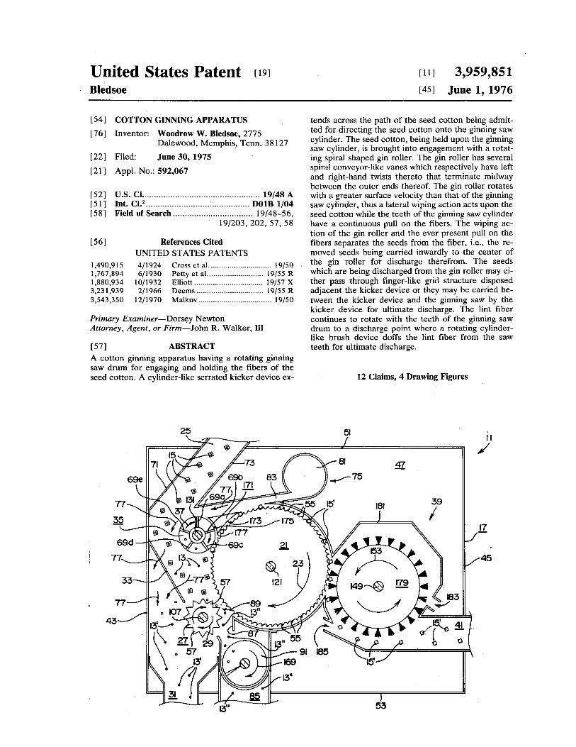
A cotton ginning apparatus having a rotating ginning saw drum for engaging and holding the fibersof the seed cotton. A cylinder-like serrated kicker device extends across the path of the seed cottonbeing admitted for directing the seed cotton onto the ginning saw cylinder. The seed cotton, beingheld upon the ginning saw cylinder, is brought into engagement with a rotating spiral shaped ginroller. The gin roller has several spiral conveyor-like vanes which respectively have left andright-hand twists thereto that terminate midway between the outer ends thereof. The gin rollerrotates with a greater surface velocity than that of the ginning saw cylinder, thus a lateral wipingaction acts upon the seed cotton while the teeth of the ginning saw cylinder have a continuous pullon the fibers. The wiping action of the gin roller and the ever present pull on the fibers separates theseeds from the fiber, i.e., the removed seeds being carried inwardly to the center of the gin roller fordischarge therefrom. The seeds which are being discharged from the gin roller may either passthrough finger-like grid structure disposed adjacent the kicker device or they may be carriedbetween the kicker device and the ginning saw by the kicker device for ultimate discharge. The lintfiber continues to rotate with the teeth of the ginning saw drum to a discharge point where a rotatingcylinder-like brush device doffs the lint fiber from the saw teeth for ultimate discharge.
Inventors: Bledsoe; Woodrow W. (2775 Dalewood, Memphis, TN 38127)Appl. No.: 592067Filed: June 30, 1975
Current U.S. Class: 19/48AIntern'l Class: D01B 001/04Field of Search: 19/48-56,203,202,57,58
References Cited [Referenced By]
U.S. Patent Documents
United States Patent: 3,959,851 http://patft.uspto.gov/netacgi/nph-Parser?Sect1=PTO1&Sect2=H...
2 of 11 6/18/03 8:05 AM
1490915 Apr., 1924 Cross et al. 19/50.1767894 Jun., 1930 Petty et al. 19/55.1880934 Oct., 1932 Elliott 19/57.3231939 Feb., 1966 Deems 19/55.3543350 Dec., 1970 Malkov 19/50.
Primary Examiner: Newton; Dorsey Attorney, Agent or Firm: Walker, III; John R.
Claims
I claim:
1. Apparatus for removing and segregating seeds from seed cotton, said apparatus comprisingframe-like housing means, a prime mover for rotatably driving certain structure of said apparatus, aginning saw cylinder for engaging and holding the fibers of the seed cotton, said ginning sawcylinder being journaled to said housing means and being coupled to said prime mover for rotationin a predetermined direction about a horizonatal axis, entry duct means disposed adjacent saidginning saw cylinder for admitting the seed cotton into said housing means, cylinder-like kickermeans disposed within said housing means and extending across the path of the seed cotton beingadmitted therein for agitating and directing the seed cotton onto said ginning saw cylinder, saidkicker means being journaled to said housing means and being coupled to said prime mover forrotation in a predetermined direction about a horizontal axis, first outlet duct means leadingoutwardly from said housing means for receiving and discharging at least a first portion of theseeds which have been removed from the seed cotton, grid means interposed between said entryduct means and said first outlet duct means for preventing passage into said first outlet duct meansof the locks of cotton and for permitting passage therethrough of the segregated seeds, spiralshaped ginning roller means coacting with said ginning saw cylinder for engaging and removing theseeds from the seed cotton, said ginning roller means being journaled to said housing means andbeing coupled to said prime mover for rotation in a predetermined direction about a horizontal axiswith the periphery thereof being a predetermined distance from the periphery of said ginning sawcylinder, doffing means for subsequently removing the lint cotton from said ginning saw cylinder,and lint cotton duct means leading outwardly from said housing means for receiving the lint cottonfrom said doffing means and for directing the lint cotton to further processing apparatus.
2. The apparatus as set forth in claim 1 in which is included deflector means interposed betweensaid entry duct means and said ginning saw cylinder for deflecting the locks of seed cotton enteringthrough said entry duct means to be caused to move along a prescribed path, said housing meanshaving a substantially disposed front plate member, said deflector means being effective to cause theprescribed path of the locks of cotton to be disposed adjacent said front plate member and at aspaced distance away from said ginning saw cylinder thus precluding coadunation of the incomingseed cotton with the seed free lint cotton being held by said ginning saw cylinder.
3. The apparatus as set forth in claim 1 in which is included air pressure wash means for dislodgingcertain foreign material from the seed free lint being held by said ginning saw cylinder, said airpressure wash means also establishing a mass of rushing air for aiding in conveying the seed cottonalong a prescribed path and for aiding in conveying the first portion of the seeds through said gridmeans for ultimate discharge outwardly through said first outlet duct means.
4. The apparatus as set forth in claim 3 in which said air pressure wash means includes a source ofair pressure, manifold means communicated with said source of air pressure, and nozzle means
United States Patent: 3,959,851 http://patft.uspto.gov/netacgi/nph-Parser?Sect1=PTO1&Sect2=H...
3 of 11 6/18/03 8:05 AM
communicated with said manifold means, said nozzle means being arranged to direct the airemanating therefrom against the circumferential surface of said ginning saw cylinder whereby thelocks of seed free cotton being held thereon are air washed, the flow of air from said nozzle meansbeing directed to flow in a direction which is opposite from the direction of travel of the surface ofsaid ginning saw cylinder.
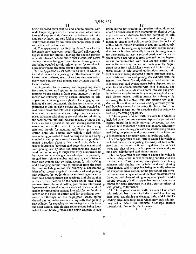
5. The apparatus as set forth in claim 1 in which is included second outlet duct means leadingoutwardly from said housing means for discharging at least a second portion of the seeds whichhave been removed from the seed cotton, and bypass means communicated with said second outletduct means for receiving the second portion of the segregated seeds from said kicker means and forintroducing these seeds to said second outlet duct means, said kicker means being disposed apredetermined spaced apart distance from said ginning saw cylinder with the generatrices thereofjointly defining at least in part an elongated gap, said bypass means being disposed subjacent to andcommunicated with said elongated gap whereby the loose seeds which enter into said gap gravitatedownwardly between said ginning saw cylinder and said kicker means thus entering said bypassmeans for ultimate discharge through said second outlet duct means.
6. The apparatus as set forth in claim 5 in which is included screw conveyor means disposedadjacent said bypass means for laterally moving the second portion of seeds into said second outletduct means, said screw conveyor means being journaled to said housing means and being coupledto said prime mover for rotation in a predetermined direction about a horizonatal axis.
7. The apparatus as set forth in claim 5 in which is included means for adjusting the effectiveness ofsaid kicker means, wherey seeds of various sizes may selectively pass between said ginning sawcylinder and said kicker means.
8. Apparatus for removing and segregating seeds from seed cotton said apparatus comprisingframe-like housing means having a front plate member, a prime mover for rotatably driving certainstructure of said apparatus, a ginning saw cylinder for engaging and holding the seed cotton, saidginning saw cylinder being journaled to said housing means and being coupled to said prime moverfor rotation in a predetermined direction about a horizonatal axis, entry duct means disposedadjacent said ginning saw cylinder for admitting the seed cotton into said housing means,cylinder-like kicker means disposed within said housing means and extending across the path ofthe seed cotton being admitted therein for agitating and directing the seed cotton onto said ginningsaw cylinder, siad kicker means being journaled to said housing means and being coupled to saidprime mover for rotation in a predetermined direction about a horizontal axis, deflector meansinterposed between said entry duct means and said ginning saw cylinder for deflecting the locks ofseed cotton entering through said entry duct means to be caused to move along a prescribed path inproximity to said front plate member and at a spaced distance from said ginning saw cylinder,means for air washing and dislodging certain foreign material from the seed free lint includingmeans for directing a continuous blast of air pressure against the surface of said ginning sawcylinder, first outlet duct means leading outwardly from said housing means for receiving anddischarging at least a first portion of the seeds which have been removed from the seed cotton, gridmeans interposed between said entry duct means and said first outlet duct means for preventingpassage into said first outlet duct means of the locks of cotton and for permitting pressuretherethrough of the segregated seeds, spiral shaped ginning roller means coating with said ginningsaw cylinder for engaging and removing the seeds from the seed cotton, said ginning roller meansbeing journaled to said housing means and being coupled to said prime mover for rotation in apredetermined direction about a horizontal axis with the periphery thereof being a predetermineddistance from the periphery of said ginning saw cylinder to enable said ginning roller means toengage and pull the seeds from the locks of cotton which remain attached to and are continuouslybeing pulled by said ginning saw cylinder, second outlet duct means leading outwardly from saidhousing means for discharging at least a second portion of the seeds which have been removedfrom the seed cotton, bypass means communicated with said second outlet duct means for receiving
United States Patent: 3,959,851 http://patft.uspto.gov/netacgi/nph-Parser?Sect1=PTO1&Sect2=H...
4 of 11 6/18/03 8:05 AM
the second portion of the segregated seeds from said kicker means and for introducing these seedsto said second outlet duct means, said kicker means being disposed a predetermined spaced apartdistance from said ginning saw cylinder with the generatrices thereof jointly defining at least in partan elongated gap, said bypass means being disposed subjacent to and communicated with saidelongated gap whereby the loose seeds which enter into said gap gravitate downwardly between theginning saw cylinder and said kicker means, doffing means for subsequently removing the lintcotton from said ginning saw cylinder, and lint cotton duct means leading outwardly from saidhousing means for receiving the lint cotton from said doffing means and for directing the lint cottonto further processing apparatus.
9. The apparatus as set forth in claim 8 in which is included screw conveyor means disposedadjacent said bypass means for laterally moving the second portion of seeds into said second outletduct means, said screw conveyor means being journaled to said housing means and being coupledto said prime mover for rotation in a predetermined direction about a horizontal axis.
10. The apparatus as set forth in claim 8 in which is included means for adjusting the width of saidelongated gap to permit optimum regulation for various types and sizes of seeds which passbetween said ginning saw cylinder and said kicker means.
11. The apparatus as set forth in claim 1 in which is included stripper bar means extending parallelwith the rotating axis of said ginning saw cylinder and being adjacent said ginning saw cylinder andsaid ginning roller means, said stripper bar being generally triangular shaped in cross-section, a firstportion of said stripper bar means being contoured for close clearance with the outer periiphery ofsaid ginning saw cylinder, and a second portion of said stripper bar means being contoured forclose clearance with the outer periphery of said ginning roller means.
12. The apparatus as set forth in claim 11 in which said stripper bar means includes a knifelikeleading edge thus establishing a cleaning unit, said knifelike leading edge deflecting seeds whichmay pass said ginning roller means for ultimate discharge thereof through said first outlet ductmeans.
Description
BACKGROUND OF THE INVENTION
1. Field of the Invention
This invention relates to the field of cotton ginning devices and is particularly directed towardginning devices which incorporate means for pneumatically conveying the cotton into the ginningapparatus.
2. Description of the Prior Art
Conventional cotton gins have arcuate ginning ribs extending between the individual saws, whichjointly constitute the ginning saw drum. The spacing between each of the saws is sufficient topermit seeds to pass between the individual saws to escape from the ginning area. For example, likethe ginning ribs shown on page 52 of a handbook entitled "Handbook for Cotton Ginners"published by the Agricultural Research Service of the United States Department of Agriculture andfurther identified as Agricultural Handbook No. 260. More specifically, this prior type of saw drumutilizes the space between the individual saw members for carrying the seeds. Accordingly, theseprior type saw drums were restricted to disk type circular saws having spacers therebetween, i.e., asopposed to garnet wire wrap type saw drums which simply have a barbed garnet wire convolutely
United States Patent: 3,959,851 http://patft.uspto.gov/netacgi/nph-Parser?Sect1=PTO1&Sect2=H...
5 of 11 6/18/03 8:05 AM
wound about a drum.
SUMMARY OF THE INVENTION
The concept of the present invention is to provide apparatus for removing seeds from seed cotton.The apparatus of the present invention may be of a permanent installation or it may be portable.More specifically, the complete system might be factory assembled and shipped as a unit, or thecomplete unit might be mounted on suitable wheels, a trailer, or truck to facilitate being transportedto the cotton field for total processing of the cotton in the field.
The cotton ginning apparatus of the present invention includes a rotating ginning saw drum forengaging and holding the fibers of the seed cotton. A cylinder-like serrated kicker device extendsacross the path of the seed cotton being admitted for directing the seen cotton onto the ginning sawcylinder. The seed cotton, being held upon the ginning saw cylinder, is brought into engagementwith a rotating spiral shaped gin roller. The gin roller has several spiral conveyor-like vanes whichrespectively have left and right-hand twists thereto that converge substantially midway between theouter ends thereof. The gin roller rotates with a greater surface velocity than that of the ginning sawcylinder, thus a lateral wiping action acts upon the seed cotton while the teeth of the ginning sawcylinder have a continuous pull on the fibers. The wiping action of the gin roller and the everpresent pull on the fibers separates the seeds from the fibers, i.e., the removed seeds being carriedinwardly by the several vanes to the center of the gin roller for discharge therefrom. The seedsbeing discharged from the gin roller may either pass through finger-like grid structure disposedadjacent the kicker device or they may be carried between the kicker device and the ginning saw bythe kicker device for ultimate discharge. The lint fiber continues to rotate with the teeth of theginning saw drum to a discharge point where a rotating cylinder-like brush device doffs the lintfibers from the saw teeth for ultimate discharge.
An important feature of the present invention is that the ginning action is accomplished entirely onthe surface of the rotating ginning saw drum. Therefore, the saws on the saw drum may be eitherdisk type with spacers or garnet wire wrap. It should be mentioned that in either type the preferredspacing between convolutions or individual disk saws is approximately 1/8 in. or 3.175 mm fromcenter to center. Another very important feature of the cotton gin of the present invention is thespiral gin roller which rotates in the same direction as the ginning saw drum. The significance of thespiral ginning roller is in the lateral wiping action thereof which provides superior seed removalresults. Another important feature of the spiral ginning roller is the deflecting action of the helicalflights, i.e., the helical flights or vanes deflect the removed seeds inwardly toward the converging leftand right-hand twists thereto. It will be appreciated by those skilled in the art that greatereffectiveness is achieved by deflecting the seeds away from the direction of the movement of thefibers, i.e., while the fibers are impaled upon the tooth structure of the saw drum, the lateral wipingaction of the spiral ginning roller separates the seeds from the fibers. This is believed to be a totallynew concept in cotton ginning. In fact, it is believed that this new concept in cotton ginning willresult in cotton being totally processed in the cotton field, as opposed to being transported to acentrally located factory-like cotton gin.
Another important feature of the cotton gin of the present invention is the introduction of the meansfor final air washing of the cotton fibers that are being held on the saw drum. This feature providesfor much cleaner cotton by removing any remaining trash, motes or remaining seeds. In otherwords, by forcing air through nozzles at a high velocity onto the saw drum, counter to the directionof the moving cotton fibers, considerable force is exerted on the cotton fibers resulting in trash,motes, or remaining seeds, being separated from the cotton fibers. The removed particles areentrained into the airstream and carried to the finger-like grid structure for ultimate dischargethrough an exhaust duct.
The ginned seeds, i.e., those which have been separated from the fiber, fall back to the serrated
United States Patent: 3,959,851 http://patft.uspto.gov/netacgi/nph-Parser?Sect1=PTO1&Sect2=H...
6 of 11 6/18/03 8:05 AM
kicker device and as a result of the agitation of the revolving kicker device are separated from theincoming cotton that is being directed to the teeth of the saw drum. A seed channel is provided forconveying the removed seeds to a screw conveyor which discharges the seeds from the apparatus. Itshould be emphasized that the air washing principle is a lint fiber cleaning system and may be usedindependent of the cotton ginning operation.
It should be pointed out that the cotton gin of the present invention is intended to normally receivethe seed cotton from a seed cotton cleaning apparatus which may be situated either at the cottonfield or at a centrally located permanent installation. Further, it may be desirable to first pass thecomingled seed cotton and trash through a cotton drier, i.e., in the event the moisture content ishigher than optimum conditions commensurate with the cleaning process. Therefore, it isanticipated that suitable cotton drying apparatus may be situated at either the cotton field or at acentrally located permanent installation.
DESCRIPTION OF THE DRAWINGS
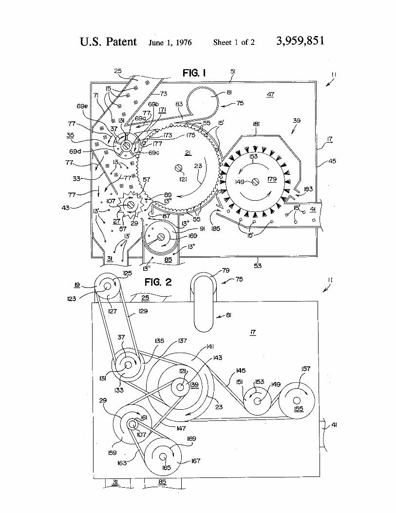
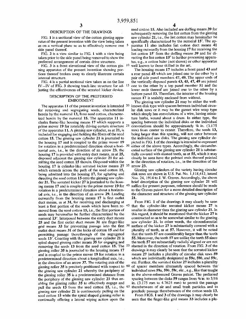
FIG. 1 is a sectional view of the cotton ginning apparatus of the present invention with the viewbeing taken as on a vertical plane so as to effectively remove one side panel thereof.
FIG. 2 is a view similar to FIG. 1 with a view being taken prior to the side panel being removed toshow the preferred arrangement of certain drive structure.
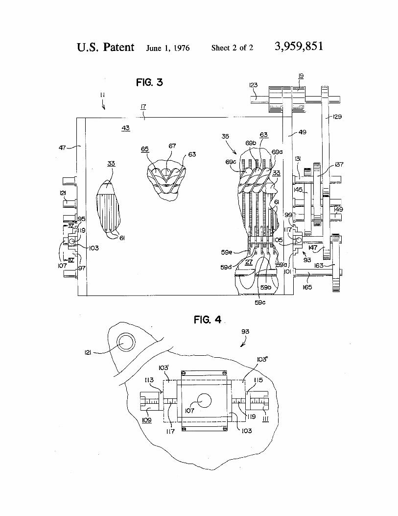
FIG. 3 is a front elevational view of the cotton ginning apparatus of the present invention showingportions thereof broken away to clearly illustrate certain internal structure.
FIG. 4 is a partial sectional view taken as on the line IV--IV of FIG. 3 showing track-line structurefor adjusting the effectiveness of the serrated kicker device.
DESCRIPTION OF THE PREFERRED EMBODIMENT
The apparatus 11 of the present invention is intended for removing and segregating seeds,characterized herein by the numeral 13, from seed cotton, characterized herein by the numeral 15.The apparatus 11 includes frame-like housing means 17 which supports a prime mover 19 forrotatably driving certain structure of the apparatus 11. A ginning saw cylinder, as at 21, is includedfor engaging and holding the fibers of the seed cotton 15. The ginning saw cylinder 21 is journaledto the housing 17 and is coupled to the prime mover 19 for rotation in a predetermined directionabout a horizontal axis, i.e., in the direction of an arrow 23. the housing 17 is provided with entryduct means, as at 25, disposed adjacent the ginning saw cylinder 21 for admitting the seed cotton 15therein. Disposed within the housing 17 is cylinder-like serrated kicker means 27 which extendsacross the path of the seed cotton 15, being admitted into the housing 17, for agitating and directingthe seed cotton 15 onto the ginning saw cylinder 21. The serrated kicker 27 is journaled to thehousing means 17 and is coupled to the prime mover 19 for rotation in a predetermined directionabout a horizontal axis, i.e., in the direction of an arrow 29. Leading outwardly from the housingmeans 17 is first outlet duct means, as at 31, for receiving and discharging at least a first portion ofthe seeds which have been removed from the seed cotton 15, i.e., the first portion of seeds mayhereinafter be further characterized by the numeral 13'. Interposed between the entry duct means 25and the first outlet duct means 31 are finger-like grid means 33 for preventing passage into the firstoutlet duct means 31 of the locks of cotton 15 and for permitting passage therethrough of thesegregated seeds 13'. Coacting with the ginning saw cylinder 21 is spiral shaped ginning rollermeans 35 for engaging and removing the seeds 13 from the seed cotton 15. The ginning roller 35 isjournaled to the housing means 17 and is coupled to the prime mover 19 for rotation in apredetermined direction about a longitudinal axis, i.e., in the direction of an arrow 37. The rotatingaxis of the ginning roller 35 is precisely positioned with respect to the ginning saw cylinder 21whereby the periphery of the ginning roller 35 is a predetermined distance from the periphery of the
United States Patent: 3,959,851 http://patft.uspto.gov/netacgi/nph-Parser?Sect1=PTO1&Sect2=H...
7 of 11 6/18/03 8:05 AM
ginning saw cylinder 21 thus enabling the ginning roller 35 to effectively engage and pull the seeds13 from the seed cotton 15, i.e., the ginning saw cylinder 21 is continuously pulling on the seedcotton 15 while the spiral shaped ginning roller is continually offering a lateral wiping action uponthe seed cotton 15. Also included are doffing means 39 for subsequently removing the lint cottonfrom the ginning saw cylinder 21, i.e., the lint cotton may hereinafter be specifically characterizedby the numeral 15'. The apparatus 11 also includes lint cotton duct means 41 leading outwardlyfrom the housing 17 for receiving the lint cotton 15' from the doffing means 39 and for directingthe lint cotton 15' to further processing apparatus, e.g., a cotton baler (not shown) or other apparatuswell known to those skilled in the art.
The housing means 17 includes a front panel 43 and a rear panel 45 which are joined one to theother by a pair of side panel members 47, 49. The upper ends of the vertically disposed panels 43,45, 47, 49 are joined one to the other by a top panel member 51 and the lower ends thereof arejoined one to the other by a bottom panel 53. Therefore, the interior of the housing means 17 issealably enclosed from without.
The ginning saw cylinder 21 may be either the well-known disk type with spacers betweenindividual circular disk saws or it may be the garnet wire wrap type which simply has convolutionsof a wire, having miniature barbs, wound about a drum. In either type, the spacing between theindividual disks or the individual convolutions should be approximately 1/8 in. (3.175 mm) fromcenter to center. Therefore, the seeds 13, being larger than this spacing, will not enter between theindividual saw disks. The ginning saw cylinder depicted in FIG. 1 of the drawings is intended torepresent either of the above types. Accordingly, the circumferential surface of the ginning sawcylinder 21 is substantially covered with slanted teeth, as at 55, which it may clearly be seen have thepointed ends thereof pointed in the direction of rotation, i.e., in the direction of the arrow 23.
Ginning saw cylinders of the variety having circular disk saws are shown in U.S. Pat. No.1,118,412, issued Nov. 24, 1914 to J. W. Graves. Accordingly, the above brief description of theginning saw cylinder 21 will suffice for present purposes, reference should be made to the Gravespatent for a more detailed description of the character and structure of the ginning saw cylinder 21.
From FIG. 1 of the drawings it may clearly be seen that the cylinder-like serrated kicker means 27is smaller in diameter than the ginning saw cylinder 21. In this regard, it should be mentioned thatthe kicker 27 is constructed so as to be somewhat similar to the ginning saw cylinder 21. In otherwords, the circumferential surface of the kicker 27 is substantially covered with a plurality of teeth,as at 57. However, it will be noted that the teeth 57 are considerably larger than the teeth 55.Moreover, the teeth 57 are unlike the teeth 55 since the teeth 57 are substantially radially aligned orare not slanted in the direction of rotation. From FIG. 3 of the drawings it may clearly be seen thatthe serrated kicker means 27 includes a plurality of circular disk saws 59 which are individuallydesignated as 59a, 59b, and 59c, etc. Further, the serrated kicker 27 includes a plurality of spacermembers alternately spaced between the individual saws 59a, 59b, 59c, etc., e.g., like that taught inthe above-referenced Graves patent. The preferred spacing between the disks 59 ranges from 1/8 in.to 3/16 in. (3.175 mm to 4.7625 mm) to permit the passage therebetween of air and small trashparticles and to preclude passage therebetween of the cotton seeds 13.
From FIGS. 1 and 3 of the drawings it may clearly be seen that the finger-like grid means 33includes a plurality of finger or rodlike members 61 having one of the respective ends thereoffixedly attached to the front panel 43 and the free ends thereof pointing downwardly toward theserrated kicker 27 and terminating adjacent thereto as indicated in FIG. 1. The spacing between therodlike members 61 is not critical, since the object of the grid means 33 is to prevent passage intothe first outlet duct means 31 of the licks of cotton 15 and to permit passage therethrough of thesegregated seeds 13', i.e., these seeds are free of lint fibers.
From the removed portions in FIG. 3 of the drawings it may clearly be seen that the spiral shaped
United States Patent: 3,959,851 http://patft.uspto.gov/netacgi/nph-Parser?Sect1=PTO1&Sect2=H...
8 of 11 6/18/03 8:05 AM
ginning roller means 35 includes a left-hand twist assembly 63 and a right-hand twist assembly 65,i.e., the left and right-hand twist assemblies 63, 65 terminating substantially midway between theends of the roller 35 at a mid portion characterized by the numeral 67. Each of the left andright-hand twist assemblies, 63, 65 preferably includes a plurality of individual continuous vanescharacterized by the numeral 69 and individually designated as 69a, 69b, 69c, etc., as best shown inFIG. 1 of the drawings, i.e., the assemblies 63, 65 are staggered to permit seeds to discharge fromeach.
The doffing means 39 may be of the well-known revolving type brush roller of the type similar tothat shown on pages 40 through 43 of the previously mentioned Argicultural Handbook No. 260.Therefore, a brief description of the doffing means 39 will suffice for present purposes; referenceshould be made to the above-mentioned handbook for a more detailed description of the characterand structure of the preferred doffing means 39. It should be understood that other well-knownmeans for detaching the lint cotton 15' from the saw cylinder 21 may alternately be employed. Also,various modifications and changes may be made in the character and form of doffing means 39herein disclosed without departing from the true spirit of the invention. For example, the lint cotton15' might be doffed from the saw cylinder 21 by a suitably directed blast of air or other structurewell known to those skilled in the art.
The entry duct means 25 includes deflector means or plate-like structure as at 71, 73 for deflectingthe locks of seed cotton 15 entering the entry duct means 25 to cause the locks of seed cotton 15 tomove along a path prescribed by the plate-like structure 71, 73 to the ginning saw cylinder 21. Thedeflector means 71, 73 are effective to cause the prescribed path of the locks of cotton 15 to bedisposed adjacent the front plate member or front panel 43 and at a spaced distance away from theginning saw cylinder 21, thus precluding co-adunation of the incoming seed cotton 15 with the seedfree lint cotton 15' being held by the ginning saw cylinder 21.
The apparatus 11 includes air pressure wash means, as at 75, for disloging certain foreign material,e.g., fine pepper dust or trash and the like, from the seed free lint cotton 15' being held by theginning saw cylinder 21. The air pressure wash means 75 establishes a mass of rushing air, i.e.,moving in the direction of arrows as at 77, for aiding in conveying the seed cotton 15 along theabove-mentioned prescribed path and for aiding in conveying the first portion of the seeds 15'through the finger-like grid means 33 for ultimate discharge outwardly through the first outlet ductmeans 31.
The air pressure wash means 75 includes a source of air pressure, e.g., a motor driven air pump 79(FIG. 2) or the like, manifold means, as at 81 (FIG. 1), communicated with the air pump 79, andnozzle means, as at 83 (FIG. 1), communicated with the manifold means 81. From FIG. 1 of thedrawings it may clearly be seen that the nozzle means 83 is arranged to direct the air, shown by thearrows 77, emanating therefrom against the circumferential surface of the ginning saw cylinder 21whereby the locks of seed free cotton 15' being held thereon are air washed. It may be seen that theflow of air from the nozzle means 83 is directed to flow in a direction which is opposite from thedirection of travel, i.e., indicated by the arrow 23, of the circumferential surface of the ginning sawcylinder 21.
The apparatus 11 also includes second outlet duct means 85 leading outwardly from the housingmeans 17 for discharging at least a second portion of the seeds which have been removed from theseed cotton 15, the second portion of the seeds may hereinafter be specifically referenced by thenumeral 13". From FIG. 1 of the drawings it may also be seen that the apparatus 11 includesbypass means 87 communicated with the second outlet duct means 85 for receiving the secondportion of the segregated seeds 13" from the kicker means 27 and for introducing these seeds 13"to the second outlet duct means 85. Further, it may be seen that the kicker means 27 is disposed apredetermined spaced apart distance from the ginning saw cylinder 21 with the generatrices thereofjointly defining at least in part an elongated gap, as at 89, the gap 89 extending the distance between
United States Patent: 3,959,851 http://patft.uspto.gov/netacgi/nph-Parser?Sect1=PTO1&Sect2=H...
9 of 11 6/18/03 8:05 AM
the side panel members 47, 49. Further, it may be seen that the bypass means 87 is disposedsubjacent to and communicated with the elongated gap 89 whereby the loose seeds 13" which enterinto the gap 89 gravitate downwardly between the ginning saw cylinder 21 and the kicker means 27thus entering the bypass means 87 for ultimate discharge through the second outlet duct means 85.
The apparatus 11 also includes screw conveyor means 91 disposed adjacent the bypass means 87for laterally moving the second portion of seeds 13" into the second outlet duct means 85. Thescrew conveyor means 91 is journaled to the side panel members 47, 49 and is suitably coupled tothe prime mover 19 for rotation in a predetermined direction about a horizontal axis. A preferredarrangement for coupling the screw conveyor means 91 to the prime mover 19 will be disclosedlater in the specification.
From FIGS. 3 and 4 of the drawings it may clearly be seen that the apparatus 11 includes means, asat 93, for adjusting the effectiveness of the serrated kicker means 27 or, more specifically, foradjusting the width of the elongated gap 89. Thus, permitting or facilitating optimum regulation forvarious types and sizes of seeds 13 which pass between the ginning saw cylinder 21 and the kickermeans 27. The means 93 preferably includes a pair of confrontingly arranged track members 95, 97fixedly attached to the side panel member 47 and a substantially identical pair of confrontinglyarranged track members 99, 101 fixedly attached to the side panel member 49. A pair of bearingblocks 103, 105 slidably engage the respective track members 95, 97; 99, 103, i.e., the kicker means27 having a rotatable shaft 107 which is carried by the bearing blocks 103, 105 in a manner wellknown to those skilled in the art. Accordingly, slidably moving the bearing blocks 103, 105 to andfro along their respective track members 95, 97; 99, 103 is effective to vary the width of theelongated gap 89.
The means 93 for adjusting the effectiveness of the kicker 27 also includes two pair ofconfrontingly arranged L shaped bracket assemblies 109, 111, i.e., one pair of bracket assemblies109, 111 being fixedly attached to the side panel member 47 and another substantially identical pairof bracket assemblies 109, 111 being fixedly attached to the panel member 49. Accordingly, sinceboth of the pairs of bracket assemblies 109, 111 are identical, only one pair will be shown in detail,as in FIG. 4 of the drawings. The L shaped bracket assemblies 109, 111 respectively include a pairof confrontingly arranged flange-like members 113, 115 which respectively are provided withthreaded apertures (not shown). The bracket assemblies 109, 111 respectively include a pair ofbolt-like members 117, 119 which are threadedly received in the apertures (not shown) provided inthe flange members 113, 115. The bolt members 117, 119 are arranged so that the ends thereofresting bear against opposite sides of the bearing block 103. Therefore, it may readily be seen thatturning the bolt members 117, 119 in one direction is effective to slidably move the bearing block103 to a position character referenced by the numeral 103'. Conversely, turning the bolt members117, 119 in an opposite direction is effective to slidably move the bearing block 103 in the oppositedirection or to a position character referenced by the numeral 103". The ginning saw cylinder 21includes a rotatable shaft 121 which is shown in FIGS. 1 through 4 of the drawings. From FIG. 4of the drawings it may be seen that moving the bearing block to the position 103' is effective indecreasing the distance between the shafts 107, 121, thus decreasing the width of the elongated gap89. Conversely, slidably moving the bearing block to the position 103" increases the distancebetween the shafts 107, 121 thus increasing the width of the elongated gap 89.
Particular attention is now directed toward FIG. 2 of the drawings wherein it may be seen that theprime mover 19 includes a rotatable shaft 123 which is rotatably driven in the direction of an arrow125. Coupled to the shaft 123 is a pulley device 127 which drives an endless belt 129. The ginningroller means 35 includes a rotatably driven shaft 131 and a pulley device 133 fixedly attachedthereto, i.e., the pulley device 133 is rotatably driven in the direction of the arrow 37 by the beltstructure 129. A second pulley device 135 is fixedly attached to the shaft 131 and which drives anendless belt 137.
United States Patent: 3,959,851 http://patft.uspto.gov/netacgi/nph-Parser?Sect1=PTO1&Sect2=H...
10 of 11 6/18/03 8:05 AM
The previously mentioned shaft 121 is rotatably driven by a pulley device 139 fixedly attachedthereto, i.e., the pulley device 139 is rotatably driven in the direction of the arrow 23 by the endlessbelt 137. A second pulley device 141 is fixedly attached to the shaft 121 and is rotatably driven inthe direction of the arrow 23 by the shaft 121. A third pulley device 143 is fixedly attached to theshaft 121 for rotation therewith in the direction of the arrow 23. The pulley device 141 drives anendless belt 145 and the pulley device 143 drives an endless belt 147.
The doffing means 39 includes a rotatable shaft 149. Fixedly attached to the shaft 149 is a pulleydevice 151 which is rotatably driven in the direction of an arrow 153 by the endless belt 145 asclearly shown in FIG. 2. An idler pulley 155 is rotatably attached to the side panel member 17 forrotation in the direction of an arrow 157, i.e., being rotatably driven by the endless belt 145 in themanner shown in FIG. 2. The kicker means 27 includes a pulley device 159 which is fixedlyattached to the shaft 107 and which is rotatably driven in the direction of the arrow 29 by theendless belt 147. A second pulley device 161 is fixedly attached to the shaft 107 and which drivesan endless belt 163. The screw conveyor means 91 includes a shaft 165 and a pulley device 167which are rotatably driven in the direction of an arrow 169 by the endless belt 163 as clearly shownin FIG. 2.
The principle of operation will now be disclosed. The cotton 15 enters the apparatus 11 through theentry duct means 25 and is forced toward the front panel 43 by air pressure which may begenerated from other apparatus, e.g., cotton cleaning apparatus as well as from air emanating fromthe nozzle 83. The cotton 15 passes downwardly with the flow of air to the cylinder-like serratedkicker means 27. The air passes between the serrated disks 59a, 59b, 59c, etc., and between thefinger grids 61 into the first outlet duct means 31. Small trash particles and motes conveyed by theair particles and motes conveyed by the air exhaust into the first outlet ducts means 31.
As the locks of cotton 15 contact the kicker means 27, which is rotating to direct the cotton 15 ontothe teeth 55 of the ginning saw cylinder 21, the cotton 15 is agitated to shake out fine trash. Thecotton fiber engages the saw teeth 55 and is lifted away from the kicker means 27. The cotton 15 isnow brought into contact with the spiral shaped ginning roller means 35 as the ginning saw cylinder21 rotates. The ginning roller 35 has several conveyor type flights or vanes 69a, 69b, 69c, etc.,secured to the center tube with the flights conveying from both the left and right ends 63, 65 towardthe midsection 67. The flights 69a, 69b, 69c, etc., are staggered so that the ends at midsection 67will discharge freely. The seeds 13 are deflected away from the fiber which is engaged by the sawteeth 55. The gin roller 35 rotates with a surface speed faster than the surface speed of the ginningsaw cylinder 21. The multiple flights or vanes 69a, 69b, 69c present a continuous barrier to the seedcotton 15 being moved by the ginning saw cylinder 21. The teeth 51 of the ginning saw cylinder 21have a continuous pull on the fiber as the ginning saw cylinder 21 rotates. Between these twocounteractions upon the fiber and seed, the seeds 13 are separated from the fiber 15' whichcontinues to move with the saw teeth 55 toward the doffing means 39. The seeds 13 which havebeen separated from the fiber 15' are deflected and forced away from the ginning saw cylinder 21by incoming seed cotton 15 on the ginning saw cylinder 21 and by the rotary movement of thevanes 69a, 69b, 69c on the ginning roller 35. The ginned seeds 13, i.e., those which have beenseparated from the lint cotton 15', fall back to the serrated kicker means 27. Thus, the agitationaffect of the teeth 57 (on the kicker means 27) separate ginned seeds from incoming seed cotton 15(the cotton 15 is being directed to the teeth 55 in the manner previously described). As the seeds 13have been cleaned of fibers they will then pass through the elongated gap 89 thence move into thescrew conveyor means 91 for ultimate discharge through the second outlet duct means 85.
The apparatus 11 includes a stripper bar 171 which extends between the side panels 47, 49 andwhich is disposed adjacent the ginning saw cylinder 21 and the ginning roller means 35. From FIG.1 of the drawings it may clearly be seen that the stripper bar 171 is generally triangular shaped incross section. More specifically, the stripper bar 171 has a portion thereof, as at 173, contoured forclose clearance with the teeth 55 and a portion thereof, as at 175, contoured for close clearance with
United States Patent: 3,959,851 http://patft.uspto.gov/netacgi/nph-Parser?Sect1=PTO1&Sect2=H...
11 of 11 6/18/03 8:05 AM
the vanes 69, 69a, 69b, 69c, etc. It should also be pointed out that the stripper bar 171 has aknifelike leading edge, as at 177, which acts as a cleaning unit and also deflects any seeds whichmay pass the ginning roller means 35 back into the airstream moving in the direction of the arrows77.
The air manifold means 81 is the air supply duct for the air nozzle means 83. The air nozzle means83 spans the total length of the ginning saw cylinder 21 forcing air into the fibers engaged with thesaw teeth 55 and dislodging mote, pepper trash, and other small particles of foreign material thatmight be detrimental to the quality of lint cotton 15'.
It must be emphasized that the air washing means 75 is a lint fiber cleaning system and may beused as an entity or independent of the apparatus 11 if desired. The foreign material dislodged fromthe fiber by the air pressure wash means 75 is forced toward the front panel 43 and is carried by theairstream through the finger-like grid means 33 where it passes into the first outlet duct means 31.
The lint cotton fibers 15' continue to rotate with the teeth 55 to the point of discharge where thedoffing means 39 doffs the lint cotton 15' from the teeth 55 and forces the ginned lint cotton 15' todischarge from the machine by air pressure which is either generated by the revolving brush shownin FIG. 1 of the drawings or by other suitable doffing means alluded to above, i.e., air pressuredoffing means or the like. It should be mentioned that the doffing means 39 as depicted in thedrawings includes a revolving brush cylinder 179 and shroud means 181 disposed circumjacent tothe brush cylinder 179. The shroud means 181 is preferably provided with a pair of openings 183,185 to enhance the ability of the brush cylinder 179 to generate a sufficient volume of air to notonly doff the lint cotton 15' from the teeth 55 but to also convey the lint cotton 15' through the lintcotton duct means 41, i.e., the openings 183, 185 provide inlets for this induced air.
An important feature of the present invention is that the ginning action is on the surface of theginning saw cylinder 21. This is believed to be a totally new concept in the state of the art of cottongins.
Although the invention has been described and illustrated with respect to a preferred embodimentthereof, it is to be understood that it is not to be so limited since changes and modifications may bemade therein which are within the full intended scope of the invention.
* * * * *