couch analysis - facultyfaculty.arch.tamu.edu/media/cms_page_media/4528/projpres.pdf · couch...
TRANSCRIPT

COUCH ANALYSISARCH 614 Tina Chanady
Ann FrankovichMorgan Harrison
Courtney KellyEllen Kiel
Winnie LamLeslie Leffke
Abby LeonardBrant Moore
David PearceDavid SeifertSi-Hyun Sung
Stefan Weissenstein
SPRING 2007

• The process and evaluation was documented to:– Model static structural behavior– Classify connections– Quantify capacity based on wood design practices
• This assignment is a practical application of taking structural formulas and concepts and applying them to a smaller, familiar object such as a couch that has similar behaving members.
Why?
Why? Process Structure Assembly Loads Description Conclusion

Process
• Upholstery removal– Fabric– Burlap– Padding– Staples
Why? Process Structure Assembly Loads Description Conclusion
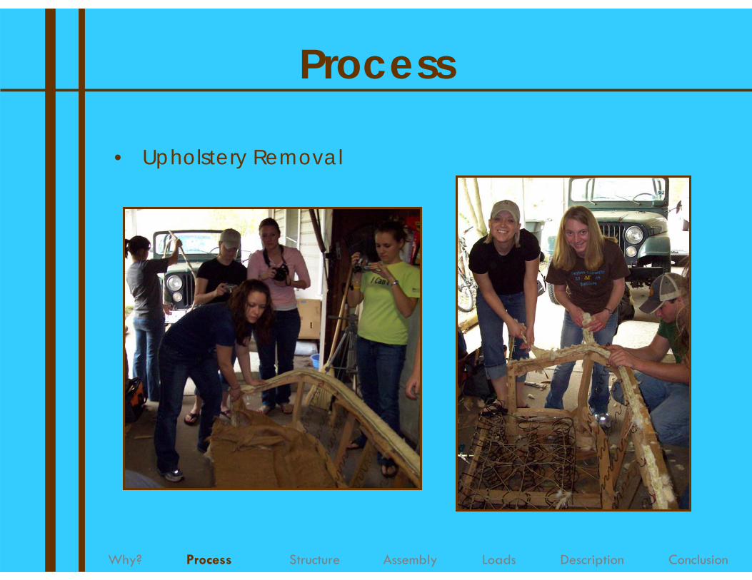
Process
• Upholstery Removal
Why? Process Structure Assembly Loads Description Conclusion

Process
• Labeling Structural Members
Why? Process Structure Assembly Loads Description Conclusion

Process
• Hardware Removal
Why? Process Structure Assembly Loads Description Conclusion

Process
• Hardware Removal
Why? Process Structure Assembly Loads Description Conclusion

Process
• Hardware Removal
Why? Process Structure Assembly Loads Description Conclusion

Process
• Measuring Components
Why? Process Structure Assembly Loads Description Conclusion

Process
• Recording Data Throughout Deconstruction
Why? Process Structure Assembly Loads Description Conclusion

Process
• Final Deconstruction
Why? Process Structure Assembly Loads Description Conclusion

Structure
Why? Process Structure Assembly Loads Description Conclusion
• General Couch Construction– Frame
• Kiln-dried hardwood1
– Springs• Eight-way hand-tied knot system1
• Metal clips 2• Coil placement2
– Connection techniques• Corners are wood glued, high pressure stapled and
reinforced with blocks.2

Structural Systems
• Structural Members– Vertical Components– Horizontal Components
Why? Process Structure Assembly Loads Description Conclusion

• Connection Types 3– Butt joints
– End lap joints
– Dowel joints
3
3
3
Why? Process Structure Assembly Loads Description Conclusion
Structural Systems

Structural Systems
• Connection Types4
– Adhesive• Wood glue
– Dowels
– Screws, Bolts, Staples
Why? Process Structure Assembly Loads Description Conclusion

• Bracing– Blocking for reinforcement
Why? Process Structure Assembly Loads Description Conclusion
5
Structural Systems

• Bracing– 8 way hand tied knot system– Burlap straps– Metal straps
Why? Process Structure Assembly Loads Description Conclusion
Structural Systems

Non-Structural Components
• Springs – used to redistribute weight throughout the frame
and as a cushioning device
Why? Process Structure Assembly Loads Description Conclusion

Assembly Order
• Step 1: Back section of couch constructed• Step 2: Arm rest sides are constructed
Why? Process Structure Assembly Loads Description Conclusion

Assembly Order
• Step 3: The sides and back are attached to the back legs.
Why? Process Structure Assembly Loads Description Conclusion

Assembly Order
• Step 4: Webbing Bridge attached to C2
Why? Process Structure Assembly Loads Description Conclusion

Assembly Order
• Step 5: The Front Legs are attached to C4• Step 6: C4, with the legs joined, is attached to the
front of the couch frame.
Why? Process Structure Assembly Loads Description Conclusion

Assembly Order
• Step 7: Bracing installed
Why? Process Structure Assembly Loads Description Conclusion

Assembly Order
• Step 8: Attachment of burlap and metal strap webbing to hold up the coil springs
Why? Process Structure Assembly Loads Description Conclusion

Assembly Order
• Step 9: Springs and heavy cord installed
Why? Process Structure Assembly Loads Description Conclusion

Assembly Order
• Step 10: Cushioning and Upholstery added
Why? Process Structure Assembly Loads Description Conclusion

Loads• Assumed Loads6
– 2 seated people– Vertical load (y-axis)
• 150 lb x 2 people = total weight of 300 lb• point load of 20 lbs on 18 fabric straps
– Lateral load (x-axis)• 55 lb/ person• Distributed load of 20 lbs/ft
Why? Process Structure Assembly Loads Description Conclusion

Loads• Abnormal Loads
– Arm rest load (z-axis load)• 175 lb/ft distributed• 175lb/ft x 1.25 ft = 219 lb total
Why? Process Structure Assembly Loads Description Conclusion
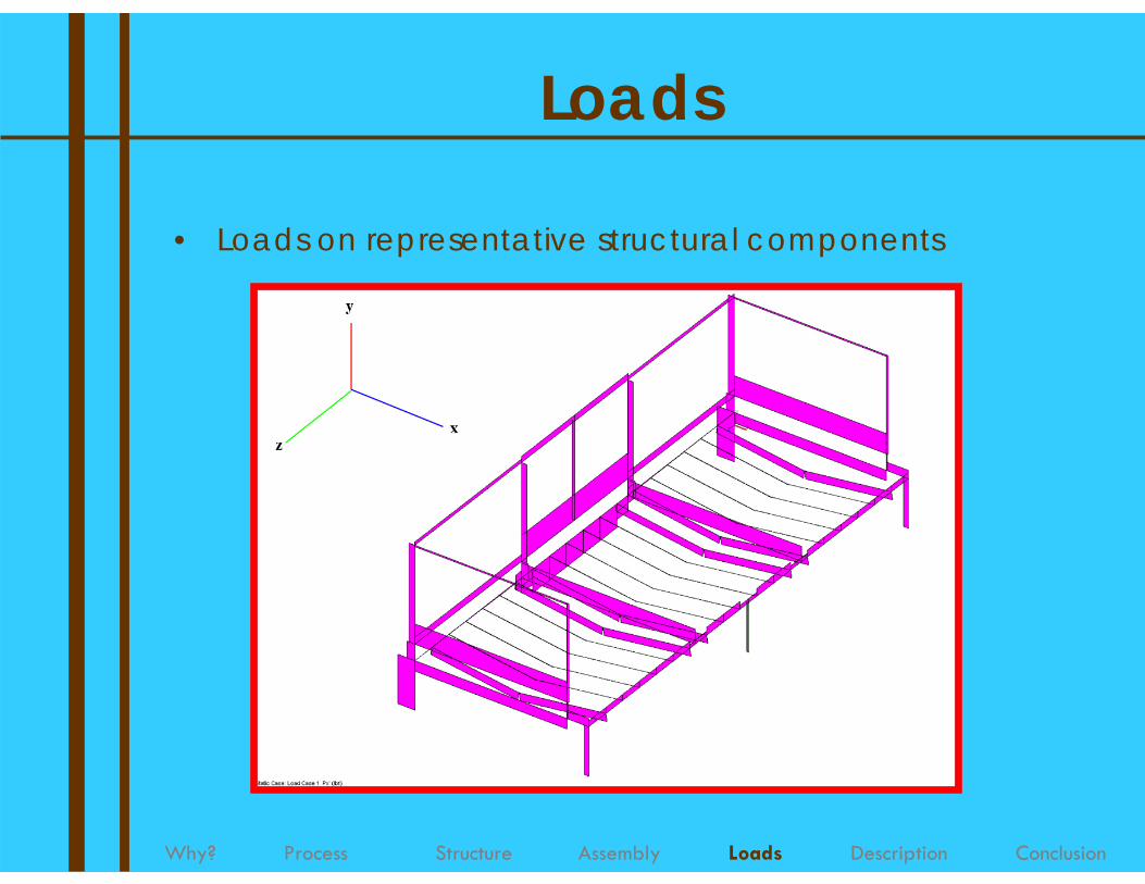
• Loads on representative structural components
Why? Process Structure Assembly Loads Description Conclusion
Loads

Description
• Deflection
Why? Process Structure Assembly Loads Description Conclusion

Description
• Moment
Why? Process Structure Assembly Loads Description Conclusion

Description
Why? Process Structure Assembly Loads Description Conclusion
0.00
100.00
200.00
300.00
400.00
500.00
600.00
PSI
A3 A4 B2 B3 C2 C3 C4 D4 D5 D6 D9 D10 E2MEMBERS
MOMENT LOADS COMPARISON
MAXIMUM MOMENTACTUAL MOMENT

Description
• Shear– Along y-axis
Why? Process Structure Assembly Loads Description Conclusion

1.00
10.00
100.00
1000.00
10000.00
PSI
A3 A4 B2 B3 C2 C3 C4 D4 D5 D6 D9 D10 E2MEMBERS
SHEAR LOADS COMPARISONLOG PLOT
MAXIMUM SHEARACTUAL SHEAR
Description
Why? Process Structure Assembly Loads Description Conclusion

Description
• Tension
Why? Process Structure Assembly Loads Description Conclusion

Description
• Compression
Why? Process Structure Assembly Loads Description Conclusion

Description
• Support
Why? Process Structure Assembly Loads Description Conclusion

Conclusion
Why? Process Structure Assembly Loads Description Conclusion
• Deconstruction– Revealing of structure and frame geometries in
addition to joint types.• Measurement of Frame
– Larger sections have greatest concentration of forces.
• Computer Models– Easy visualization from various loading conditions.
• The use of visual models to simulate numerical situations creates a great furniture design tool.

References1. www.hickorychair.com
2. www.mitchellgold.com
3. http://www.dixieline.com/woodjoint/woodjoints.htm
4. http://www.auf.asn.au/scratchbuilder/joints.html#adhesive_types
5. http://www.madehow.com/Volume-3/Sofa.html
6. Eckelman, Carl A. Textbook of Product Engineering and Strength Design of Furniture. Purdue University, West Lafayette, Indiana. January 15, 2003. (Professor of Wood science @ Purdue University)