counters registers
TRANSCRIPT
7/31/2019 Counters Registers
http://slidepdf.com/reader/full/counters-registers 1/56
Counters and
Shift Registers
7/31/2019 Counters Registers
http://slidepdf.com/reader/full/counters-registers 2/56
2
Flip-Flop Applications
• Applications of Flip-Flop:-
– Counters
• Asynchronous Counter
• Synchronous Counter
– Register
7/31/2019 Counters Registers
http://slidepdf.com/reader/full/counters-registers 3/56
3
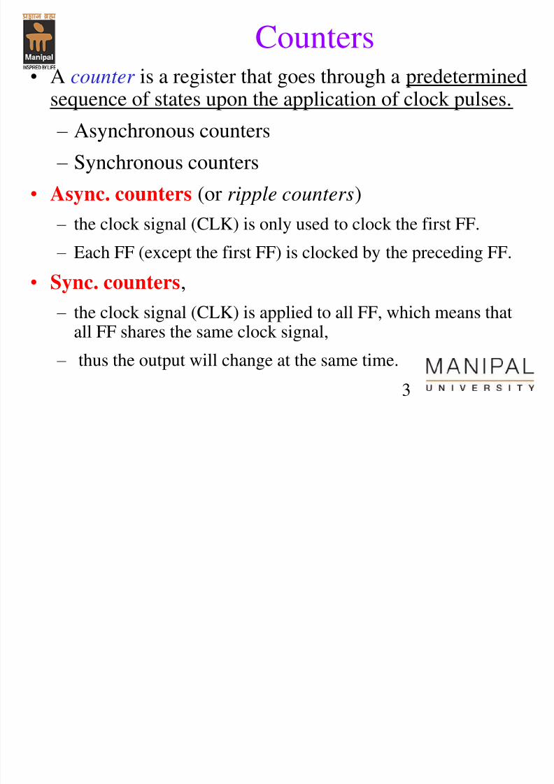
Counters• A counter is a register that goes through a predetermined
sequence of states upon the application of clock pulses.
– Asynchronous counters
– Synchronous counters
• Async. counters (or ripple counters)
– the clock signal (CLK) is only used to clock the first FF.
– Each FF (except the first FF) is clocked by the preceding FF.
• Sync. counters, – the clock signal (CLK) is applied to all FF, which means that
all FF shares the same clock signal,
– thus the output will change at the same time.
7/31/2019 Counters Registers
http://slidepdf.com/reader/full/counters-registers 4/56
4
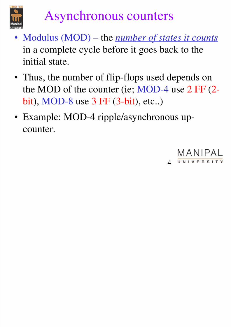
Asynchronous counters
• Modulus (MOD) – the number of states it counts in a complete cycle before it goes back to the
initial state.
• Thus, the number of flip-flops used depends onthe MOD of the counter (ie; MOD-4 use 2 FF (2-
bit), MOD-8 use 3 FF (3-bit), etc..)
• Example: MOD-4 ripple/asynchronous up-counter.
7/31/2019 Counters Registers
http://slidepdf.com/reader/full/counters-registers 5/56
5
Asynchronous Counters (continue)
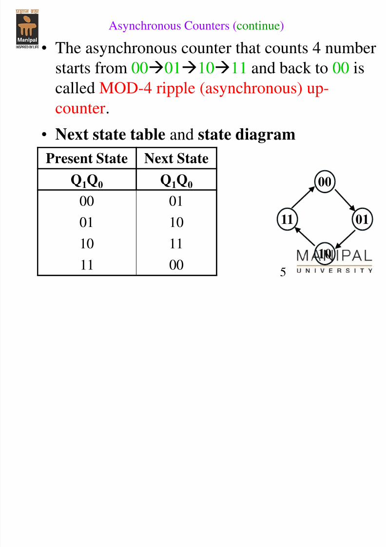
• The asynchronous counter that counts 4 number
starts from 00011011 and back to 00 iscalled MOD-4 ripple (asynchronous) up-
counter.
• Next state table and state diagram
Present State Next State
Q1Q0 Q1Q0
00 01
01 10
10 11
11 00
00
01
10
11
7/31/2019 Counters Registers
http://slidepdf.com/reader/full/counters-registers 6/56
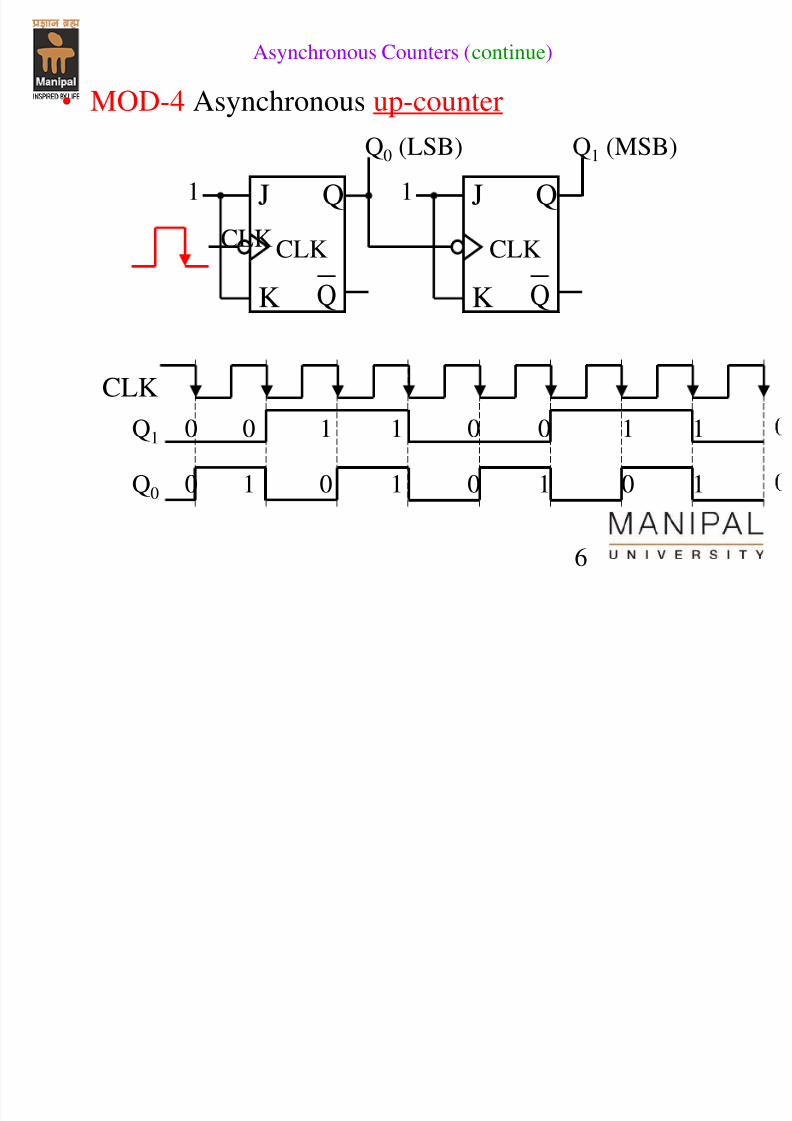
6
• MOD-4 Asynchronous up-counter
J Q
K Q
CLK
1 J Q
K Q
CLK
1
Q0 (LSB)
Q1 (MSB)
CLK
Q1 0 0 1 1 0 0 1 1
Q0 0 1 0 1 0 1 0 1
Asynchronous Counters (continue)
CLK
7/31/2019 Counters Registers
http://slidepdf.com/reader/full/counters-registers 7/567
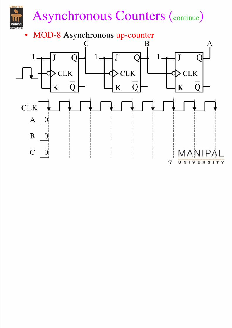
• MOD-8 Asynchronous up-counter
J Q
K Q
CLK
1 J Q
K Q
CLK
1 J Q
K Q
CLK
1
C B A
A 0
B 0
C 0
CLK
Asynchronous Counters (continue)
7/31/2019 Counters Registers
http://slidepdf.com/reader/full/counters-registers 8/568
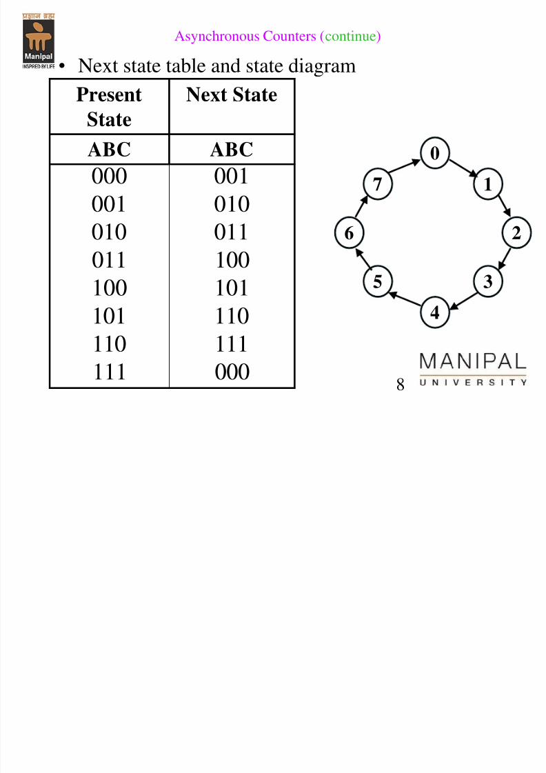
• Next state table and state diagram
PresentState
Next State
ABC ABC
000 001001 010
010 011
011 100
100 101
101 110
110 111
111 000
0
1
2
3
7
6
5
4
Asynchronous Counters (continue)
7/31/2019 Counters Registers
http://slidepdf.com/reader/full/counters-registers 9/56
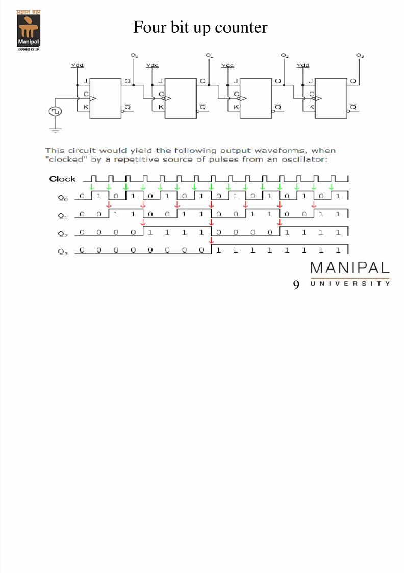
Four bit up counter
9
7/31/2019 Counters Registers
http://slidepdf.com/reader/full/counters-registers 10/56
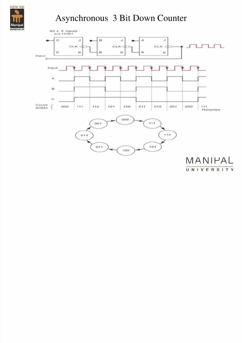
Asynchronous 3 Bit Down Counter
7/31/2019 Counters Registers
http://slidepdf.com/reader/full/counters-registers 11/5611
• So far, we have design the counters with MOD
number equal to 2N, where N is the number of bit (N =
1,2,3,4….) (also correspond to number of FF)
• Thus, the counters are limited on for counting MOD-2,
MOD4, MOD-8, MOD-16 etc..
• The question is how to design a MOD-5, MOD-6,
MOD-7, MOD-9 which is not a MOD-2N (MOD 2N)
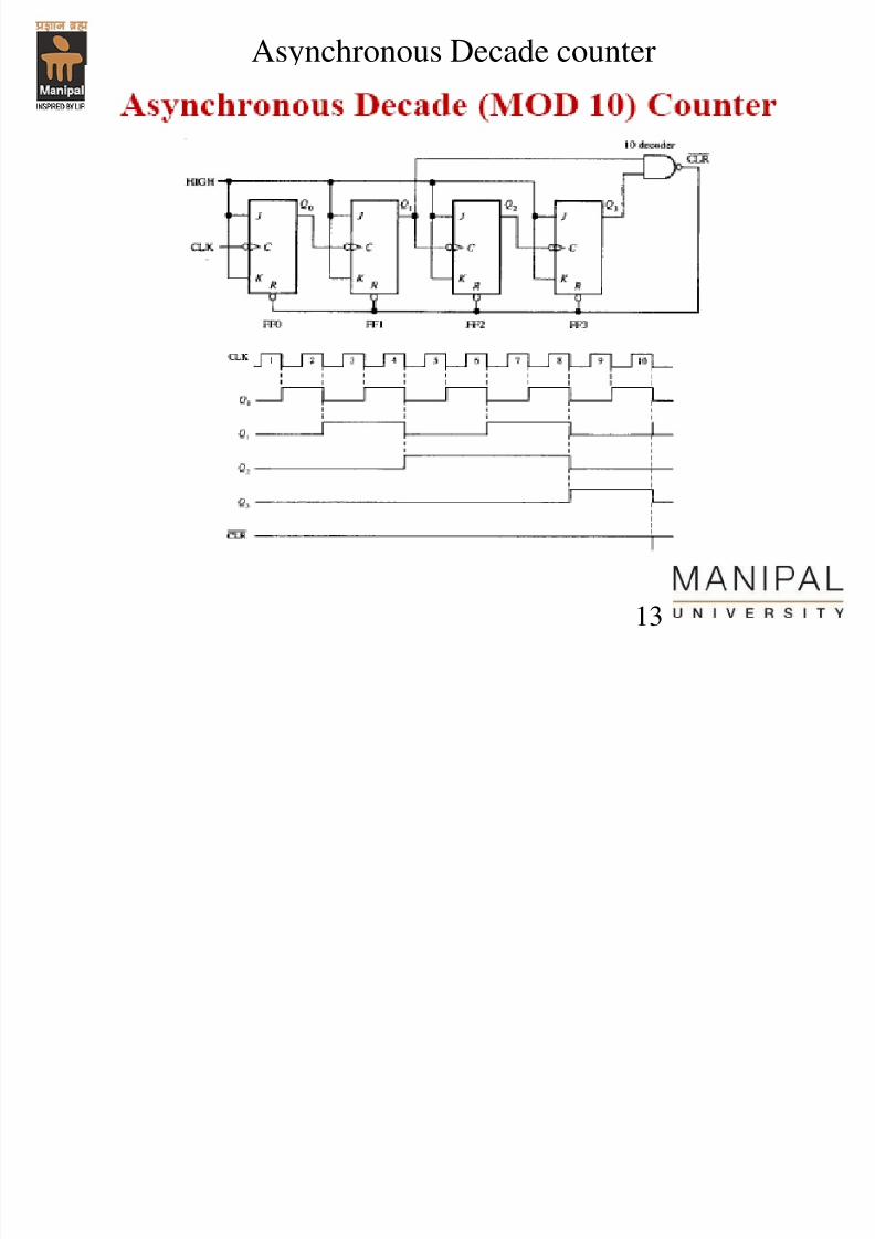
?• MOD-6 counters will count from 010 (0002) to
510(1012) and after that will recount back to 010 (0002)
continuously.
Asynchronous Counters (continue)
7/31/2019 Counters Registers
http://slidepdf.com/reader/full/counters-registers 12/56
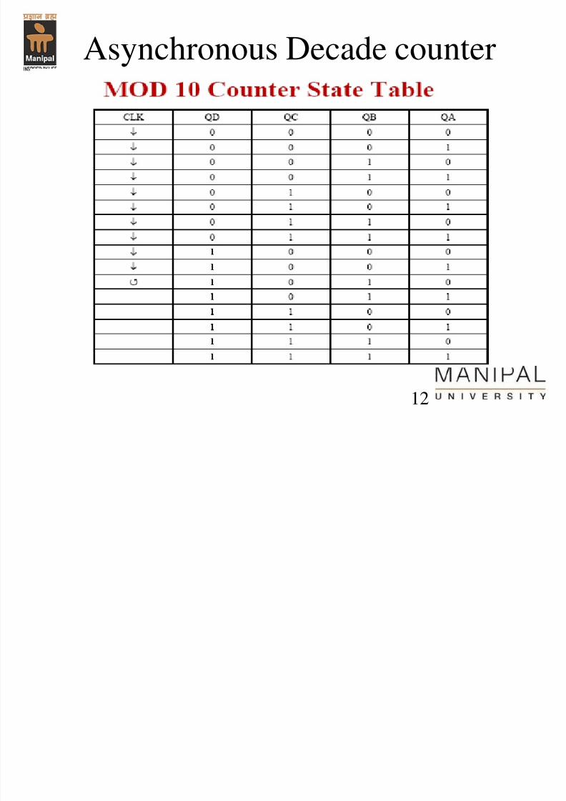
Asynchronous Decade counter
12
7/31/2019 Counters Registers
http://slidepdf.com/reader/full/counters-registers 13/56
Asynchronous Decade counter
13
7/31/2019 Counters Registers
http://slidepdf.com/reader/full/counters-registers 14/56
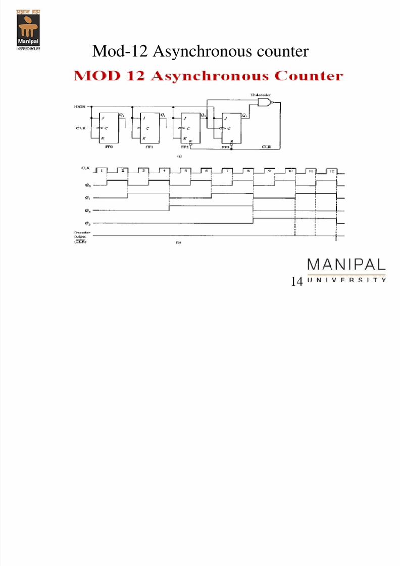
Mod-12 Asynchronous counter
14
7/31/2019 Counters Registers
http://slidepdf.com/reader/full/counters-registers 15/5615
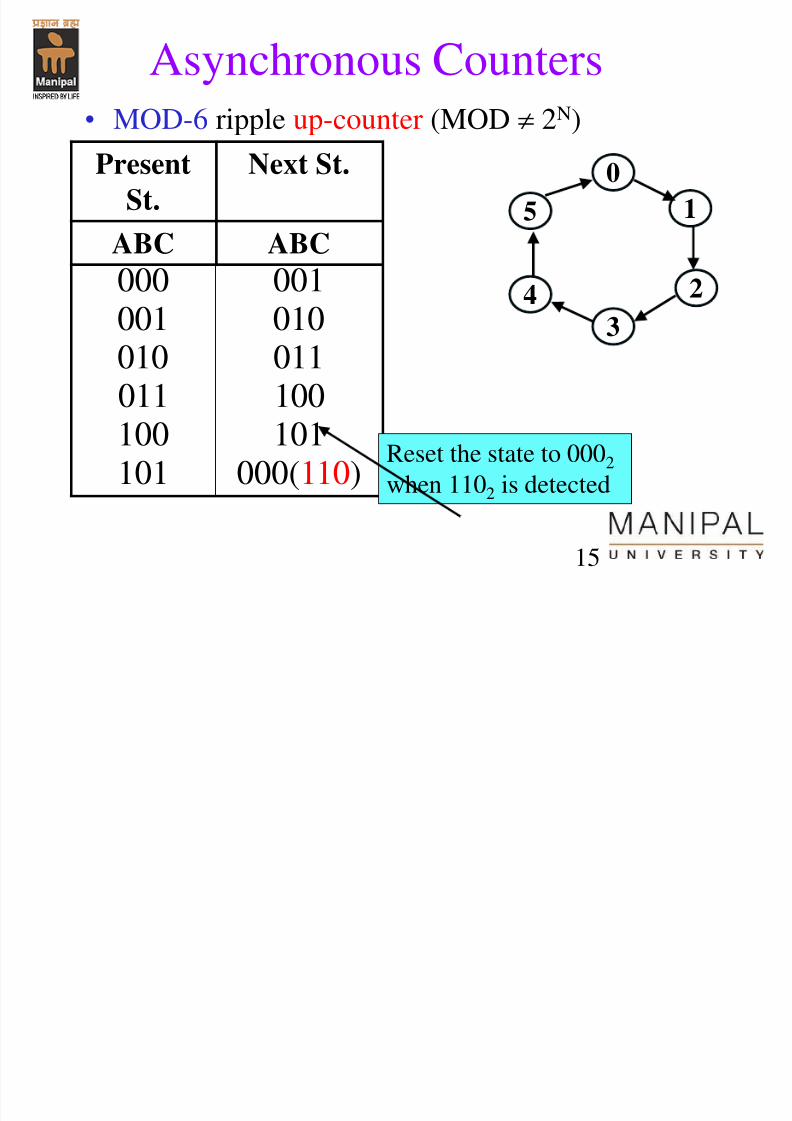
Asynchronous Counters
• MOD-6 ripple up-counter (MOD 2N)
Present
St.
Next St.
ABC ABC
000 001001 010010 011
011 100100 101101 000(110)
0
1
2
3
5
4
Reset the state to 0002
when 1102 is detected
7/31/2019 Counters Registers
http://slidepdf.com/reader/full/counters-registers 16/56
16
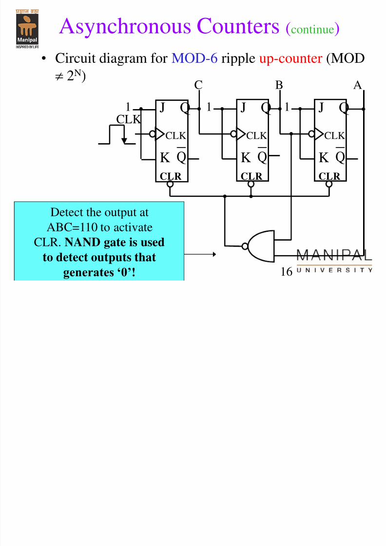
Asynchronous Counters (continue)
• Circuit diagram for MOD-6 ripple up-counter (MOD
2N)
J Q
K
CLR
Q
CLK
1 1 1
C B A
J Q
K
CLR
Q
CLK
J Q
K
CLR
Q
CLK
Detect the output at
ABC=110 to activate
CLR. NAND gate is used
to detect outputs that
generates ‘0’!
CLK
7/31/2019 Counters Registers
http://slidepdf.com/reader/full/counters-registers 17/56
17
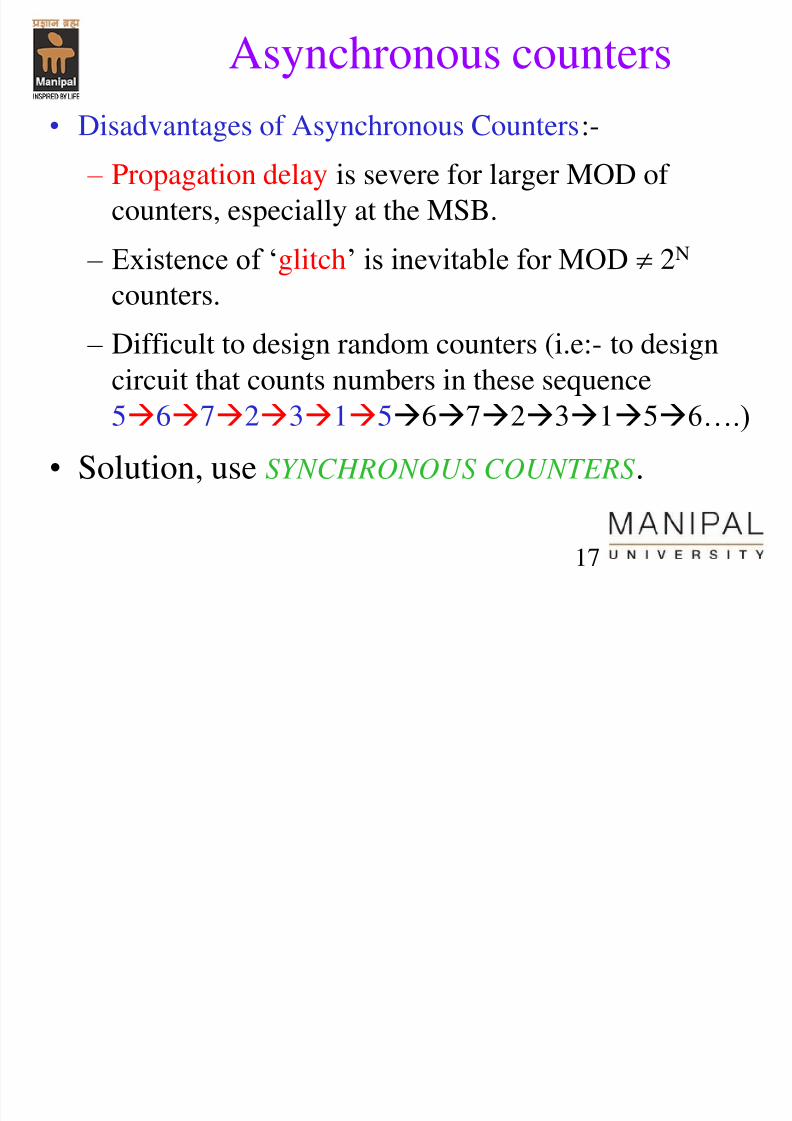
Asynchronous counters
• Disadvantages of Asynchronous Counters:- – Propagation delay is severe for larger MOD of
counters, especially at the MSB.
– Existence of „glitch‟ is inevitable for MOD
2N
counters.
– Difficult to design random counters (i.e:- to design
circuit that counts numbers in these sequence
56723156723156….)
• Solution, use SYNCHRONOUS COUNTERS.
7/31/2019 Counters Registers
http://slidepdf.com/reader/full/counters-registers 18/56
18
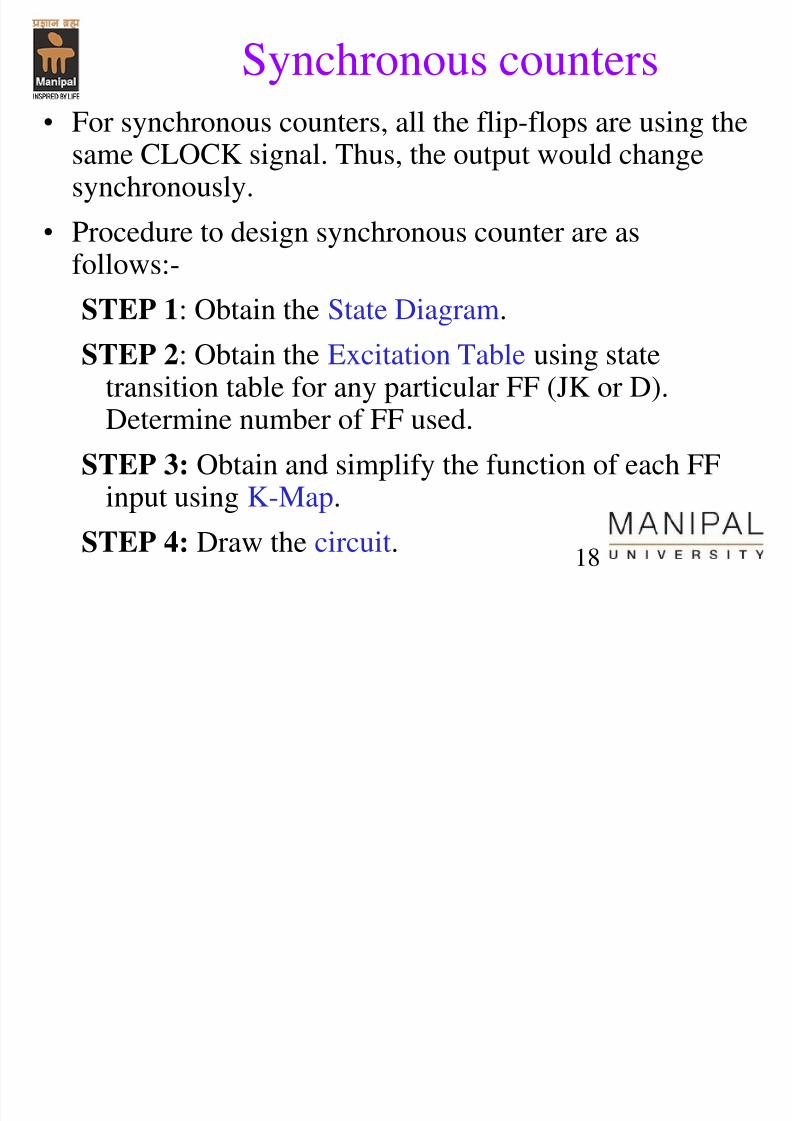
Synchronous counters
• For synchronous counters, all the flip-flops are using thesame CLOCK signal. Thus, the output would changesynchronously.
• Procedure to design synchronous counter are as
follows:-STEP 1: Obtain the State Diagram.
STEP 2: Obtain the Excitation Table using statetransition table for any particular FF (JK or D).Determine number of FF used.
STEP 3: Obtain and simplify the function of each FFinput using K-Map.
STEP 4: Draw the circuit.
7/31/2019 Counters Registers
http://slidepdf.com/reader/full/counters-registers 19/56
19
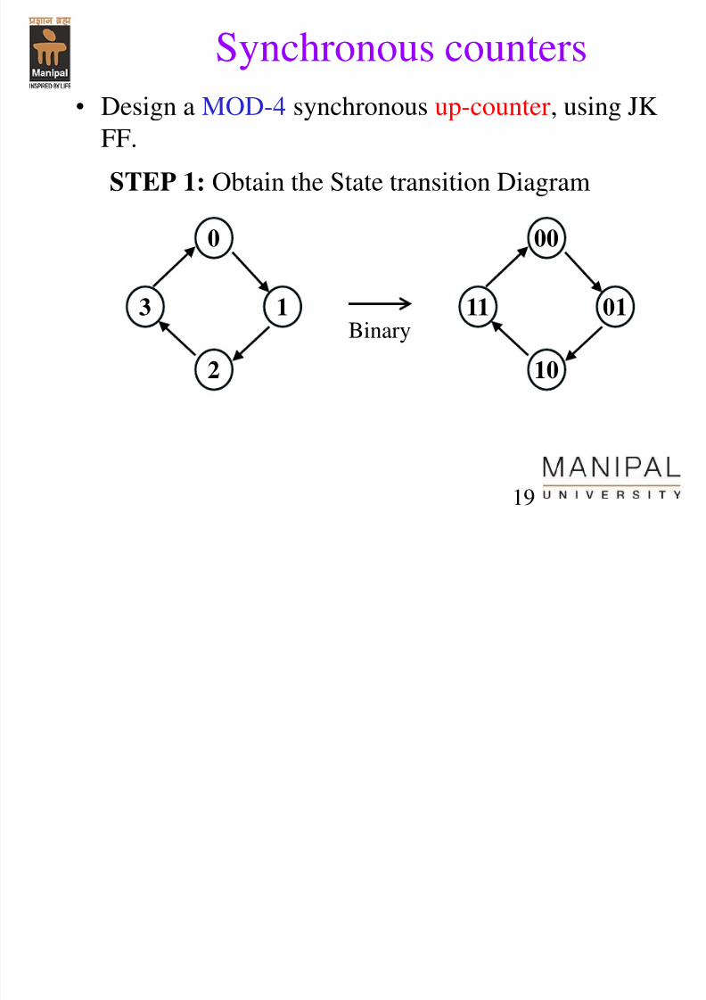
Synchronous counters
• Design a MOD-4 synchronous up-counter, using JK
FF.
STEP 1: Obtain the State transition Diagram
0
1
2
3
00
01
10
11Binary
7/31/2019 Counters Registers
http://slidepdf.com/reader/full/counters-registers 20/56
20
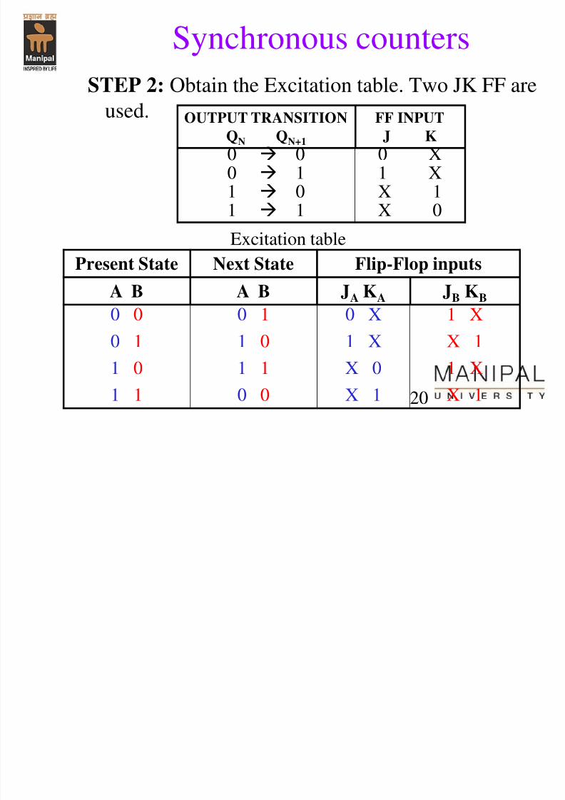
Synchronous counters
STEP 2: Obtain the Excitation table. Two JK FF are
used.
Present State Next State Flip-Flop inputs
A B A B JA KA JB KB
0 0 0 1 0 X 1 X
0 1 1 0 1 X X 1
1 0 1 1 X 0 1 X
1 1 0 0 X 1 X 1
OUTPUT TRANSITION
QN QN+1
FF INPUT
J K
0 0 0 X0 1 1 X
1 0 X 11 1 X 0
Excitation table
7/31/2019 Counters Registers
http://slidepdf.com/reader/full/counters-registers 21/56
21
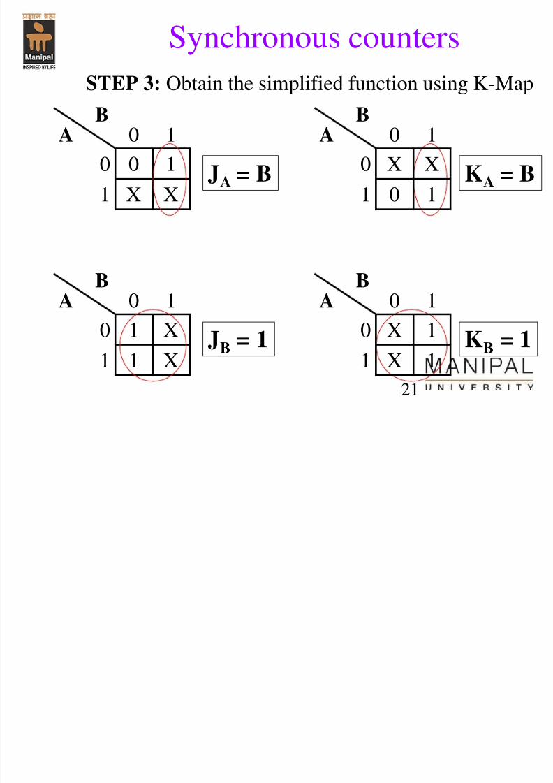
Synchronous counters
STEP 3: Obtain the simplified function using K-Map
BA 0 1
0 0 1
1 X X
JA = B
BA 0 1
0 X X
1 0 1
KA = B
BA 0 1
0 1 X
1 1 XJB = 1
BA 0 1
0 X 1
1 X 1KB = 1
7/31/2019 Counters Registers
http://slidepdf.com/reader/full/counters-registers 22/56
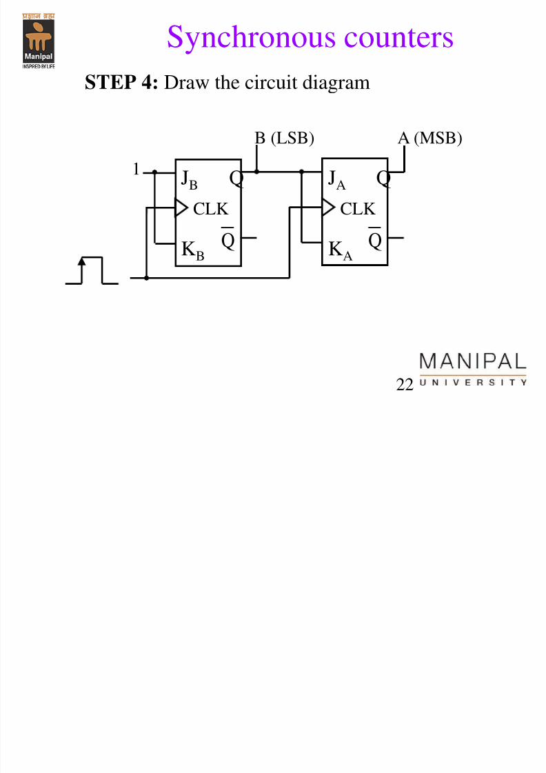
22
Synchronous counters
STEP 4: Draw the circuit diagram
JB Q
KB Q
CLK
1
JA Q
KA Q
CLK
B (LSB) A (MSB)

7/31/2019 Counters Registers
http://slidepdf.com/reader/full/counters-registers 23/56
23
Synchronous counters
• Design a MOD-4 synchronous down-counter, using JKFF?
STEP 1: Obtain the State transition Diagram
0
3
2
1
00
11
10
01Binary
S h t
7/31/2019 Counters Registers
http://slidepdf.com/reader/full/counters-registers 24/56
24
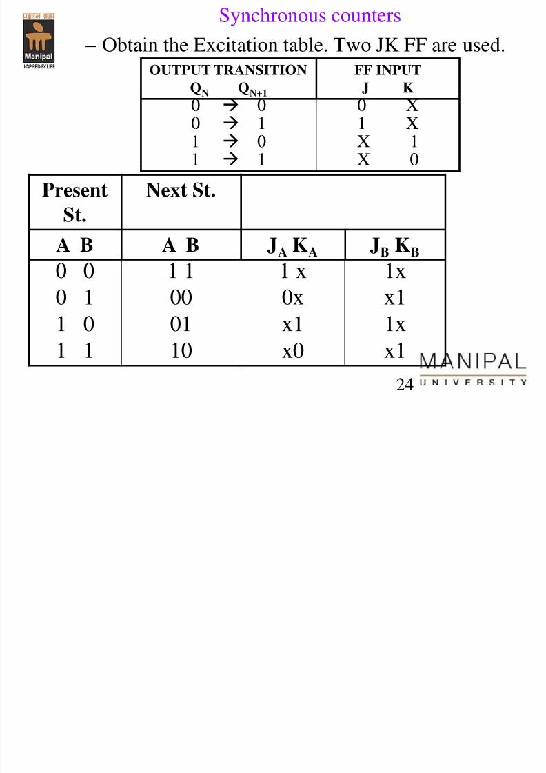
Synchronous counters
– Obtain the Excitation table. Two JK FF are used.
PresentSt.
Next St.
A B A B JA KA JB KB
0 0 1 1 1 x 1x0 1 00 0x x1
1 0 01 x1 1x
1 1 10 x0 x1
OUTPUT TRANSITION
QN
QN+1
FF INPUT
J K
0 0 0 X0 1 1 X1 0 X 11 1 X 0
7/31/2019 Counters Registers
http://slidepdf.com/reader/full/counters-registers 25/56
25
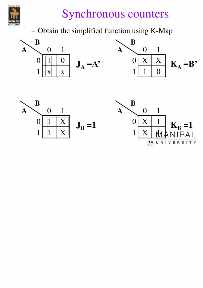
Synchronous counters
– Obtain the simplified function using K-Map
BA 0 1
0 1 0
1 x x
JA =A’
BA 0 1
0 X X
1 1 0
KA =B’
BA 0 1
0 1 X
1 1 XJB =1
BA 0 1
0 X 1
1 X 1KB =1
7/31/2019 Counters Registers
http://slidepdf.com/reader/full/counters-registers 26/56
26
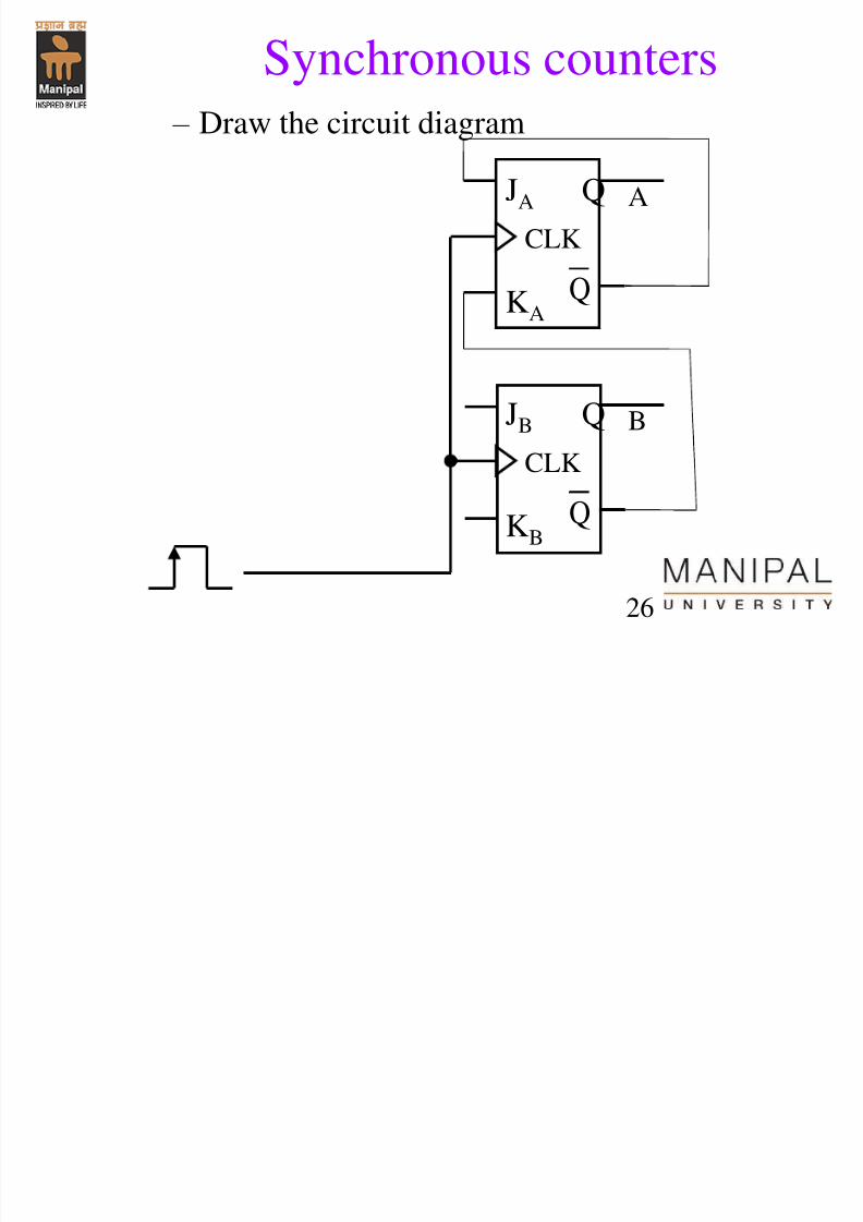
Synchronous counters
– Draw the circuit diagram
JB Q
KB Q
CLK
JA Q
KA Q
CLK
B
A
7/31/2019 Counters Registers
http://slidepdf.com/reader/full/counters-registers 27/56
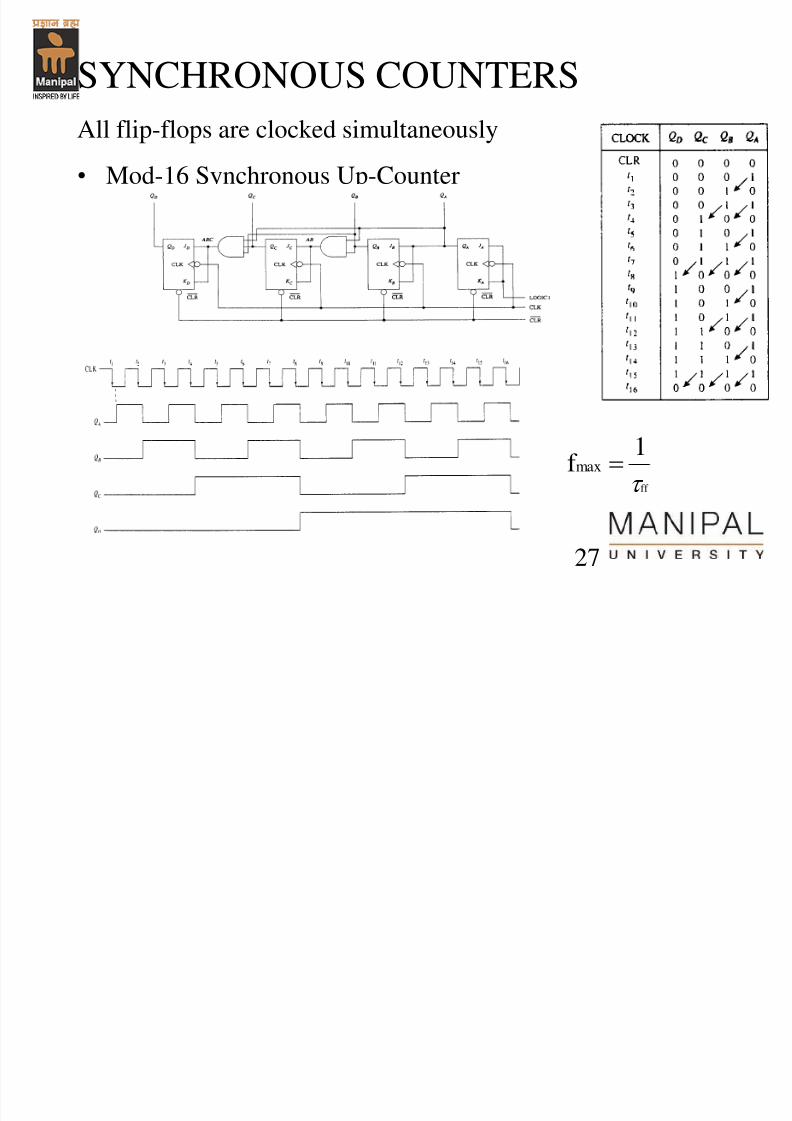
27
SYNCHRONOUS COUNTERS
All flip-flops are clocked simultaneously• Mod-16 Synchronous Up-Counter
ff
1f max
7/31/2019 Counters Registers
http://slidepdf.com/reader/full/counters-registers 28/56
28
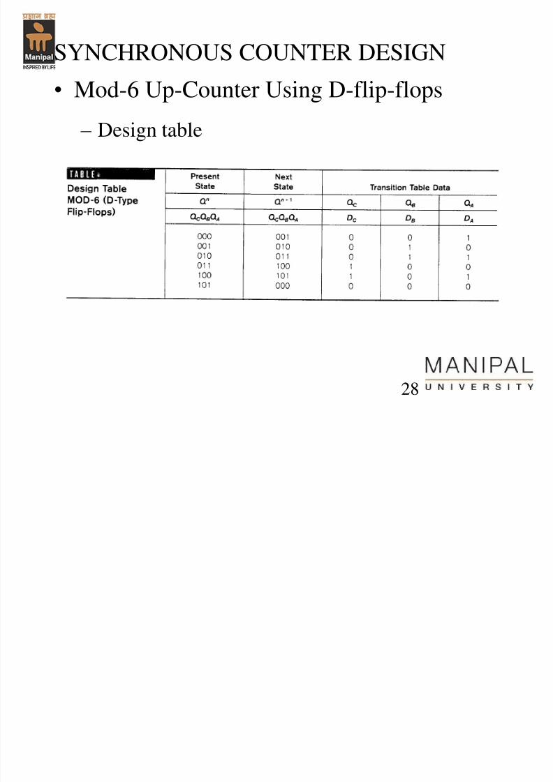
SYNCHRONOUS COUNTER DESIGN
• Mod-6 Up-Counter Using D-flip-flops – Design table
7/31/2019 Counters Registers
http://slidepdf.com/reader/full/counters-registers 29/56
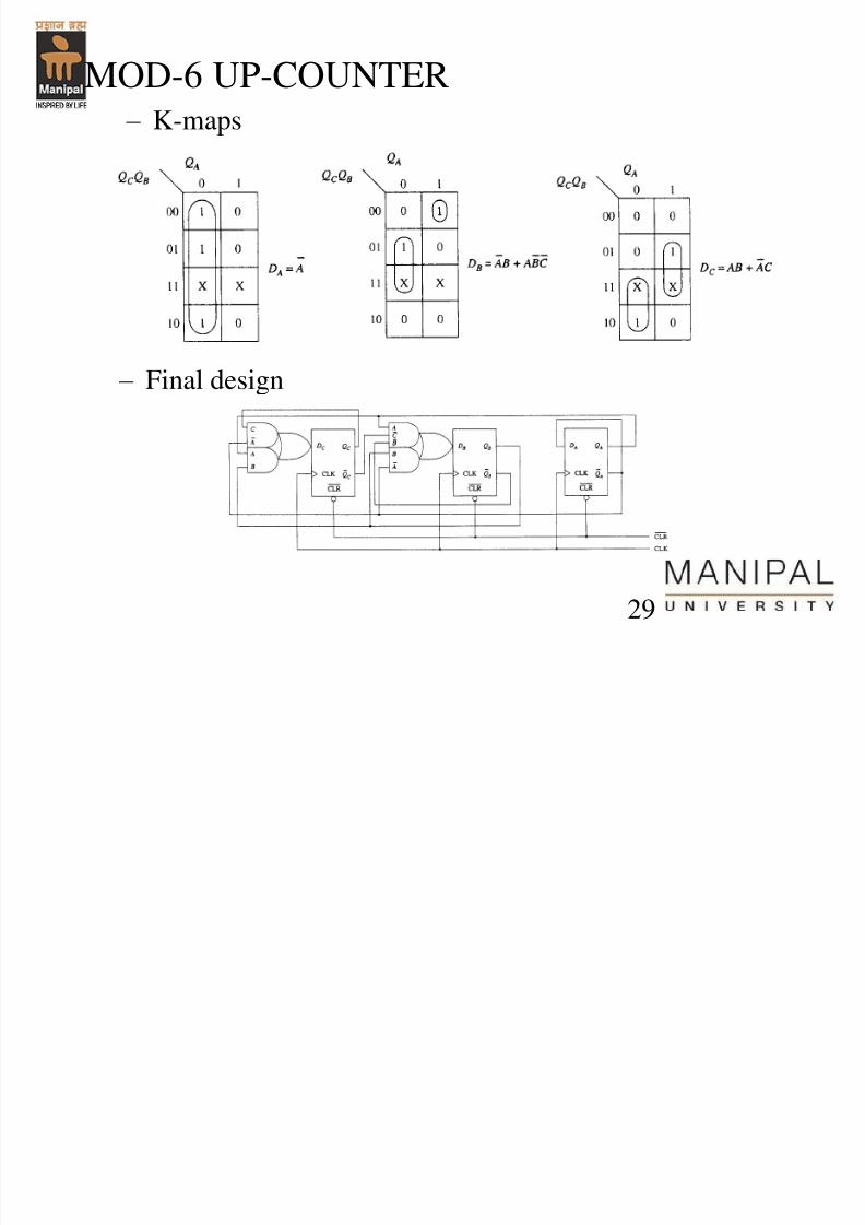
29
MOD-6 UP-COUNTER – K-maps
– Final design
7/31/2019 Counters Registers
http://slidepdf.com/reader/full/counters-registers 30/56
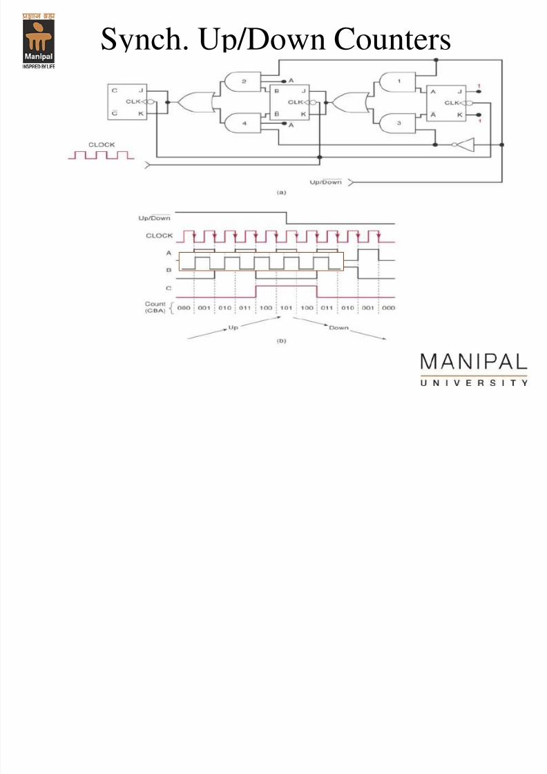
Synch. Up/Down Counters
7/31/2019 Counters Registers
http://slidepdf.com/reader/full/counters-registers 31/56
31
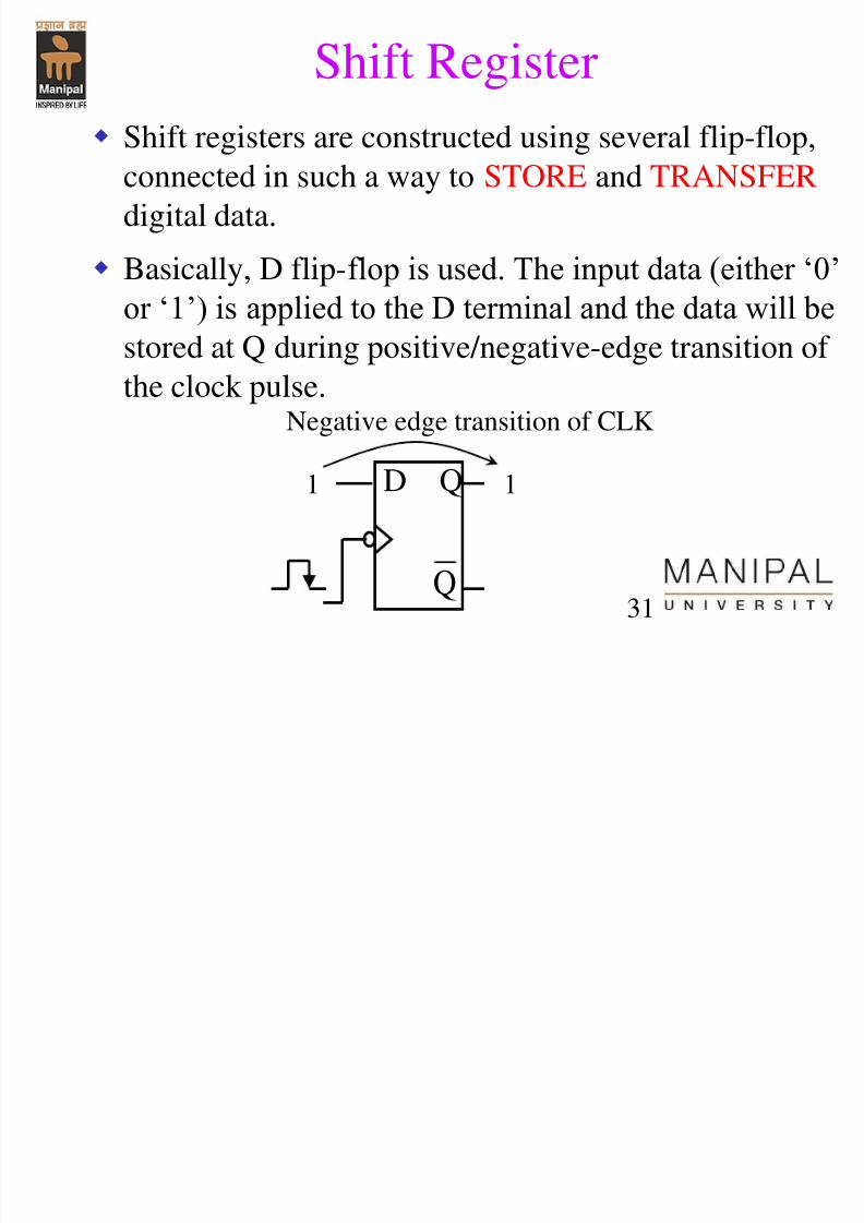
Shift Register
Shift registers are constructed using several flip-flop,connected in such a way to STORE and TRANSFER
digital data.
Basically, D flip-flop is used. The input data (either „0‟
or „1‟) is applied to the D terminal and the data will bestored at Q during positive/negative-edge transition of
the clock pulse.
D Q
Q
1 1
Negative edge transition of CLK
7/31/2019 Counters Registers
http://slidepdf.com/reader/full/counters-registers 32/56
32
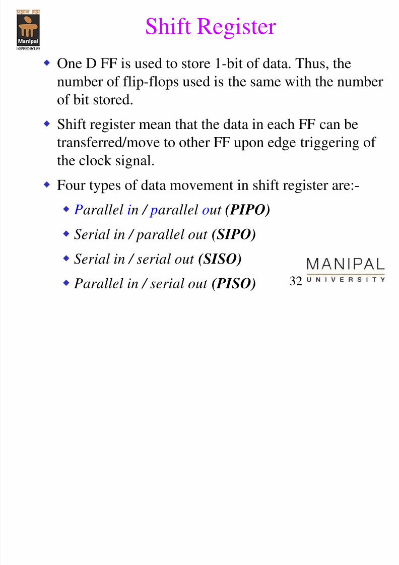
One D FF is used to store 1-bit of data. Thus, thenumber of flip-flops used is the same with the number
of bit stored.
Shift register mean that the data in each FF can be
transferred/move to other FF upon edge triggering of the clock signal.
Four types of data movement in shift register are:-
Parallel in / parallel out (PIPO)
Serial in / parallel out (SIPO)
Serial in / serial out (SISO)
Parallel in / serial out (PISO)
Shift Register
7/31/2019 Counters Registers
http://slidepdf.com/reader/full/counters-registers 33/56
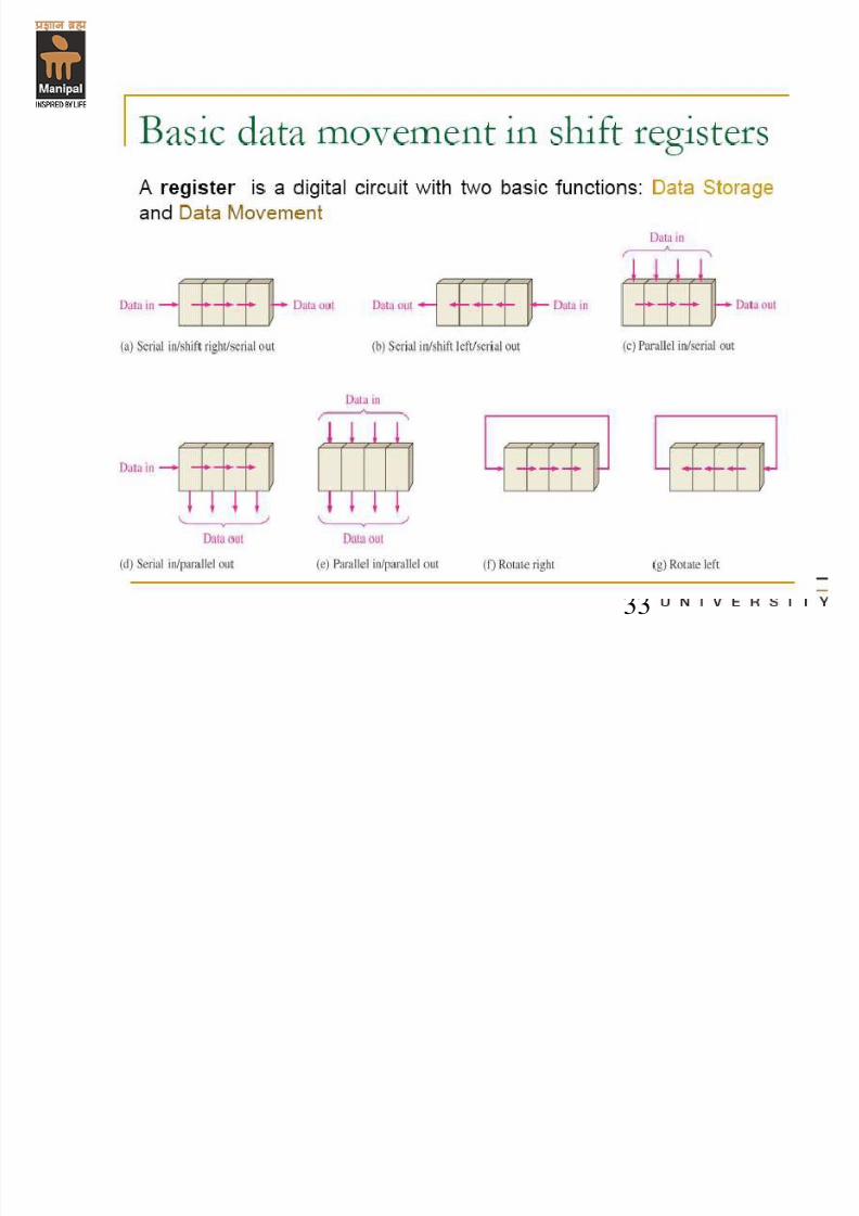
Shift Register
33
7/31/2019 Counters Registers
http://slidepdf.com/reader/full/counters-registers 34/56
34
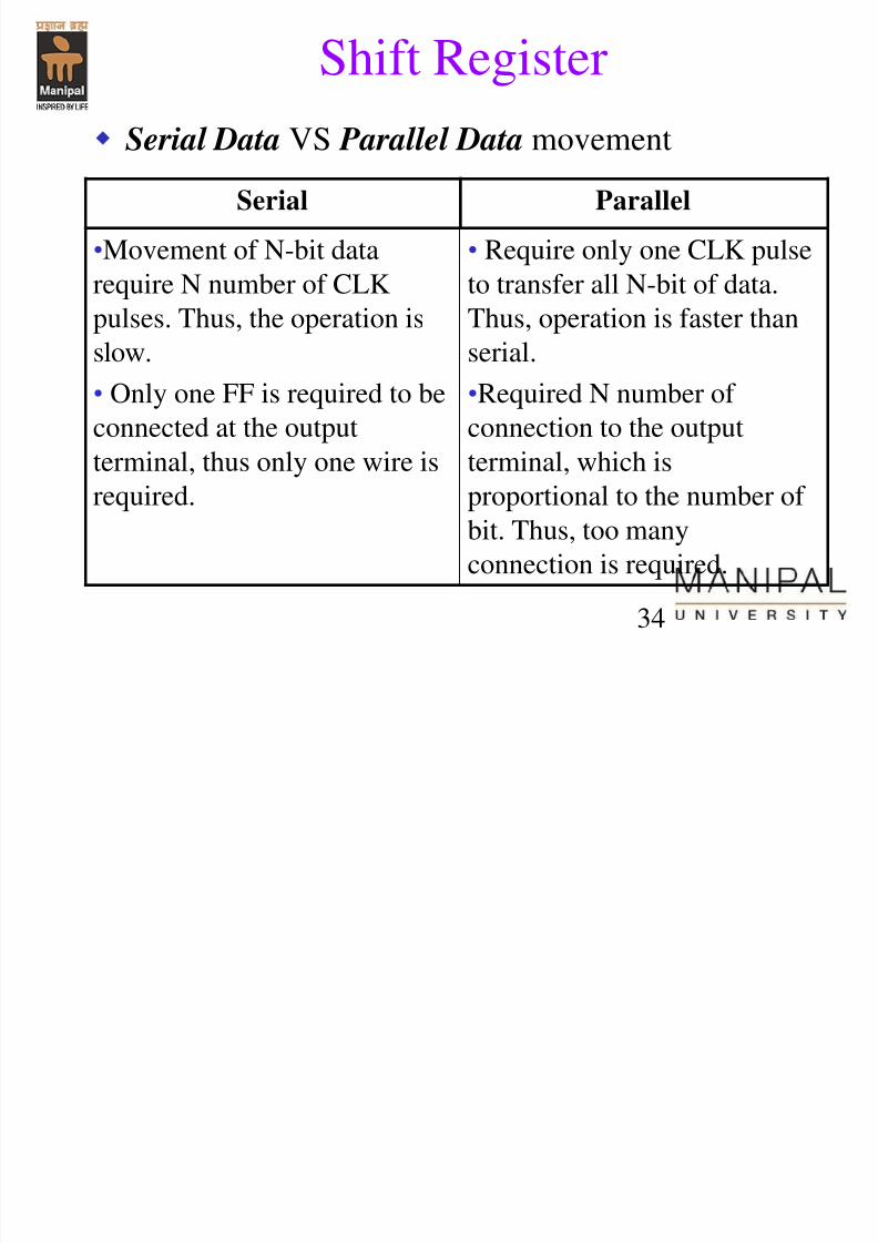
Serial Data VS Parallel Data movement
Serial Parallel
•Movement of N-bit data
require N number of CLK
pulses. Thus, the operation is
slow.
• Only one FF is required to be
connected at the output
terminal, thus only one wire isrequired.
• Require only one CLK pulse
to transfer all N-bit of data.
Thus, operation is faster than
serial.
•Required N number of
connection to the output
terminal, which isproportional to the number of
bit. Thus, too many
connection is required.
Shift Register
Parallel in / parallel out
7/31/2019 Counters Registers
http://slidepdf.com/reader/full/counters-registers 35/56
35
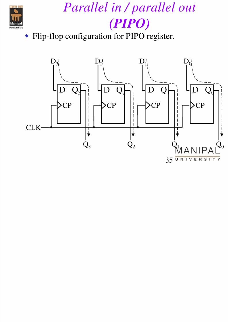
Parallel in / parallel out
(PIPO)
Flip-flop configuration for PIPO register.
D Q2
CP
D Q1
CP
D Q3
CP
D Q0
CP
CLK
D3 D2 D1 D0
Q3 Q2 Q1 Q0
Parallel in / parallel out
7/31/2019 Counters Registers
http://slidepdf.com/reader/full/counters-registers 36/56
36
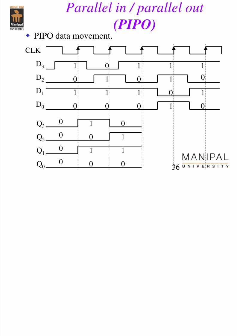
PIPO data movement.
Q3
Q2
CLK
Q1
Q0
1 0 1 1 1
0
0
0
0
1 0 100
0
0
1 1 1 1
0 0 1 0
D3
D2
D1
D0
1
0
1
0
0
1
1
0
Parallel in / parallel out
(PIPO)
7/31/2019 Counters Registers
http://slidepdf.com/reader/full/counters-registers 37/56
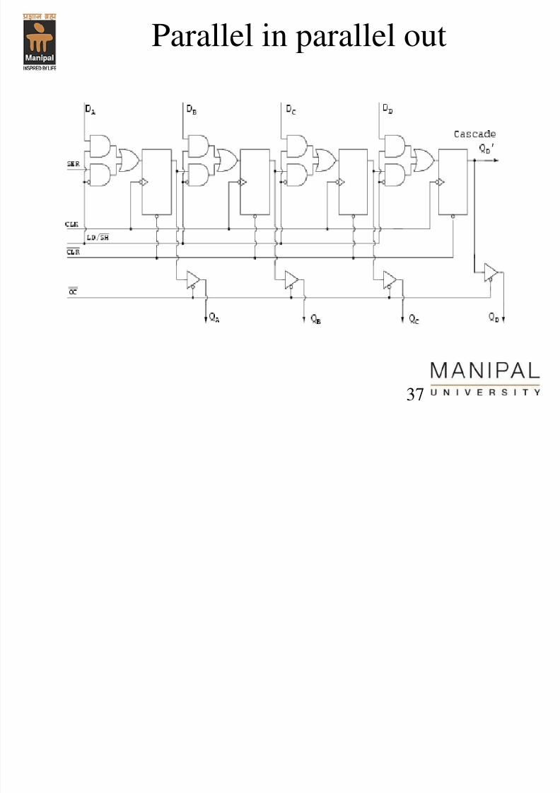
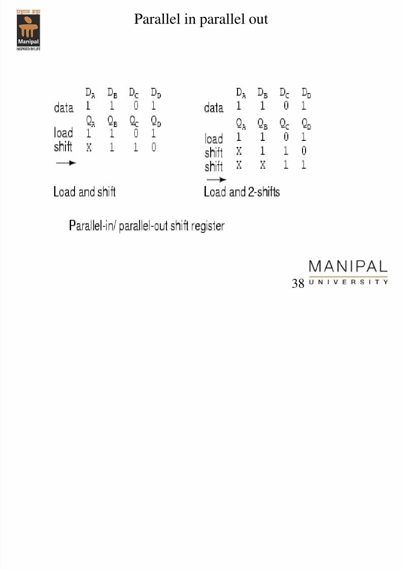
Parallel in parallel out
37
7/31/2019 Counters Registers
http://slidepdf.com/reader/full/counters-registers 38/56
Parallel in parallel out
38
7/31/2019 Counters Registers
http://slidepdf.com/reader/full/counters-registers 39/56
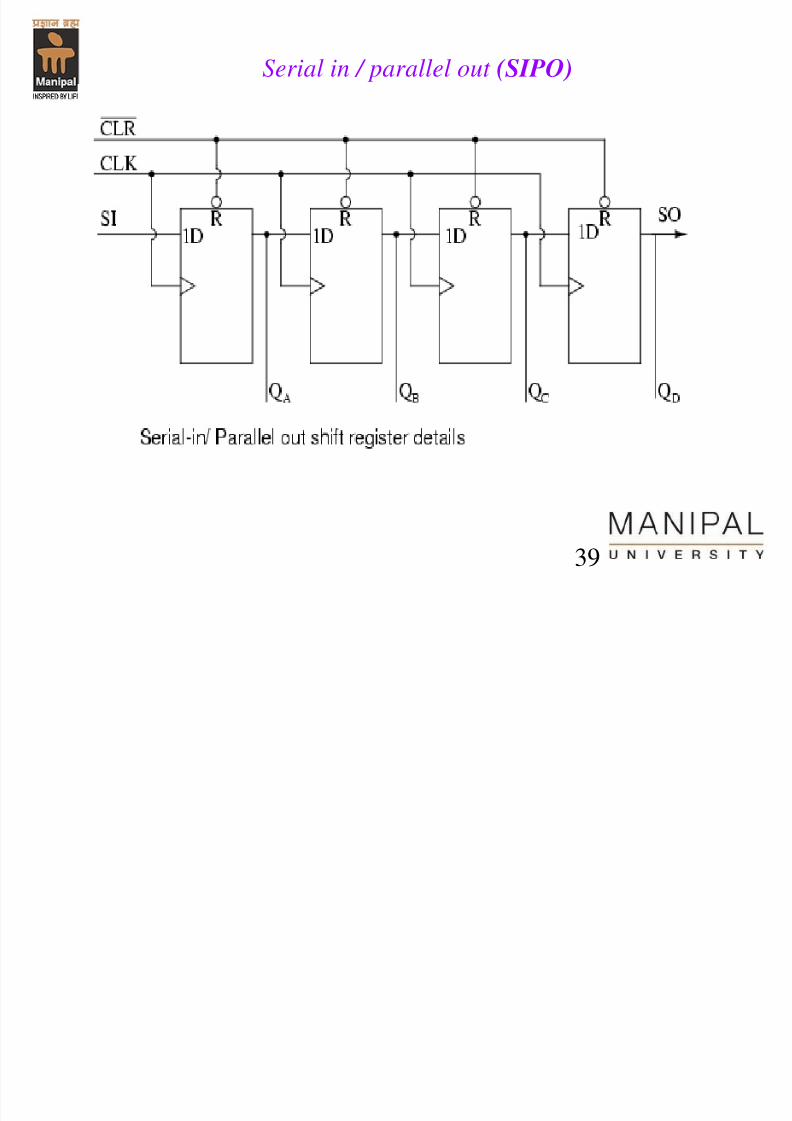
Serial in / parallel out (SIPO)
39
7/31/2019 Counters Registers
http://slidepdf.com/reader/full/counters-registers 40/56
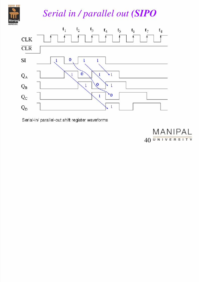
Serial in / parallel out (SIPO
40
7/31/2019 Counters Registers
http://slidepdf.com/reader/full/counters-registers 41/56
41
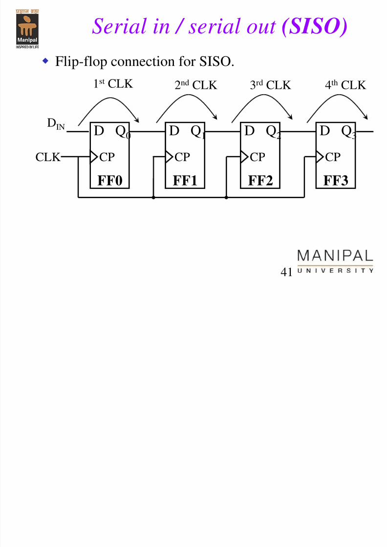
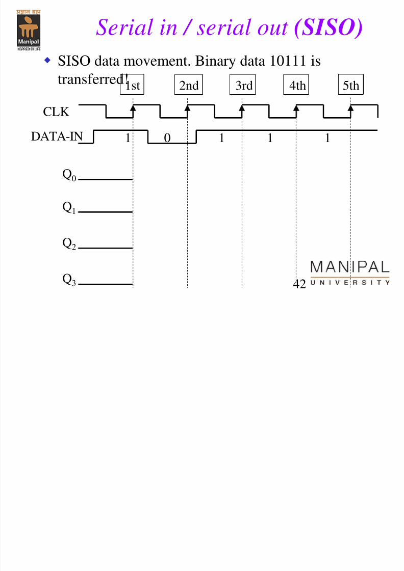
Serial in / serial out (SISO)
Flip-flop connection for SISO.
D Q1
FF1
CP
D Q2
FF2
CP
D Q0
FF0
CP
D Q3
FF3
CPCLK
DIN
1st CLK 2nd CLK 3rd CLK 4th CLK
7/31/2019 Counters Registers
http://slidepdf.com/reader/full/counters-registers 42/56
42
SISO data movement. Binary data 10111 is
transferred!
DATA-IN
Q0
Q1
1st
CLK
2nd 3rd 4th 5th
Q2
Q3
Serial in / serial out (SISO)
1 0 1 1 1
7/31/2019 Counters Registers
http://slidepdf.com/reader/full/counters-registers 43/56
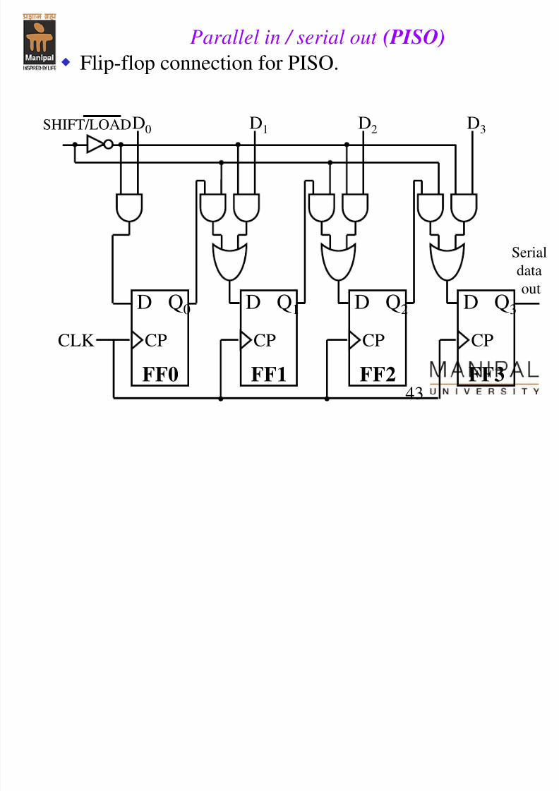
43
Flip-flop connection for PISO.
Parallel in / serial out (PISO)
D Q1
FF1
CP
D Q2
FF2
CP
D Q0
FF0
CP
D Q3
FF3
CPCLK
D0 D1 D2 D3 SHIFT/LOAD
Serial
data
out
7/31/2019 Counters Registers
http://slidepdf.com/reader/full/counters-registers 44/56
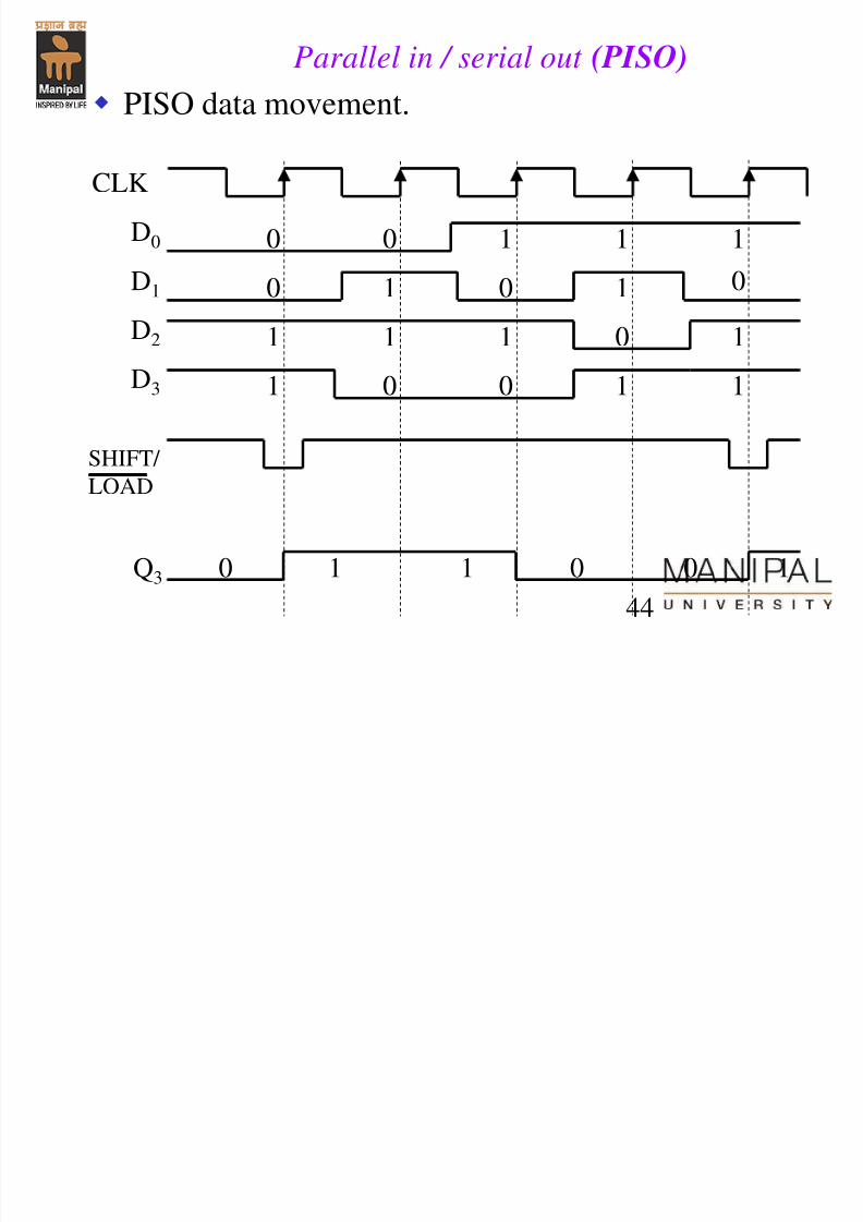
44
PISO data movement.
SHIFT/
LOAD
CLK
Q3
0
0 1 1 1
1 0 1
0
0
0
1
1 1 1 1
0 0 1 1
D0
D1
D2
D3
1 0
Parallel in / serial out (PISO)
0 1 0 1
7/31/2019 Counters Registers
http://slidepdf.com/reader/full/counters-registers 45/56
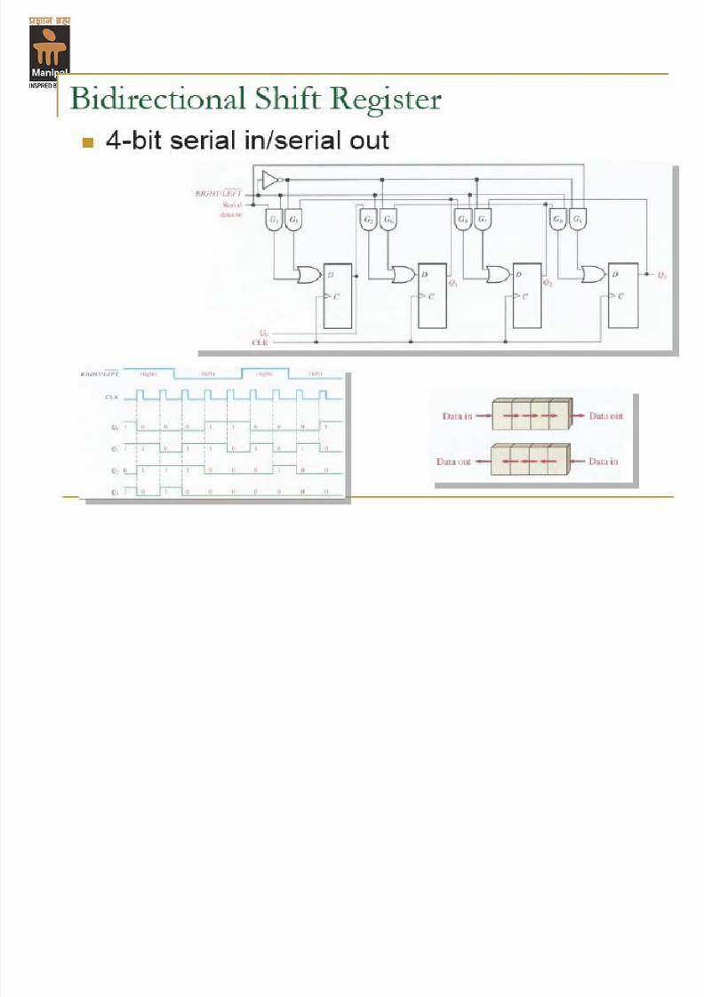
Bidirectional shift Register
45
7/31/2019 Counters Registers
http://slidepdf.com/reader/full/counters-registers 46/56
46
A shift register counter is a shift register whose output
being fed back (connected back) to the serial input.
This shift register would count the state in a unique
sequence!
Two types of shift register counter:-
The ring counter
The Johnson counter
Shift Register Counters
7/31/2019 Counters Registers
http://slidepdf.com/reader/full/counters-registers 47/56
47
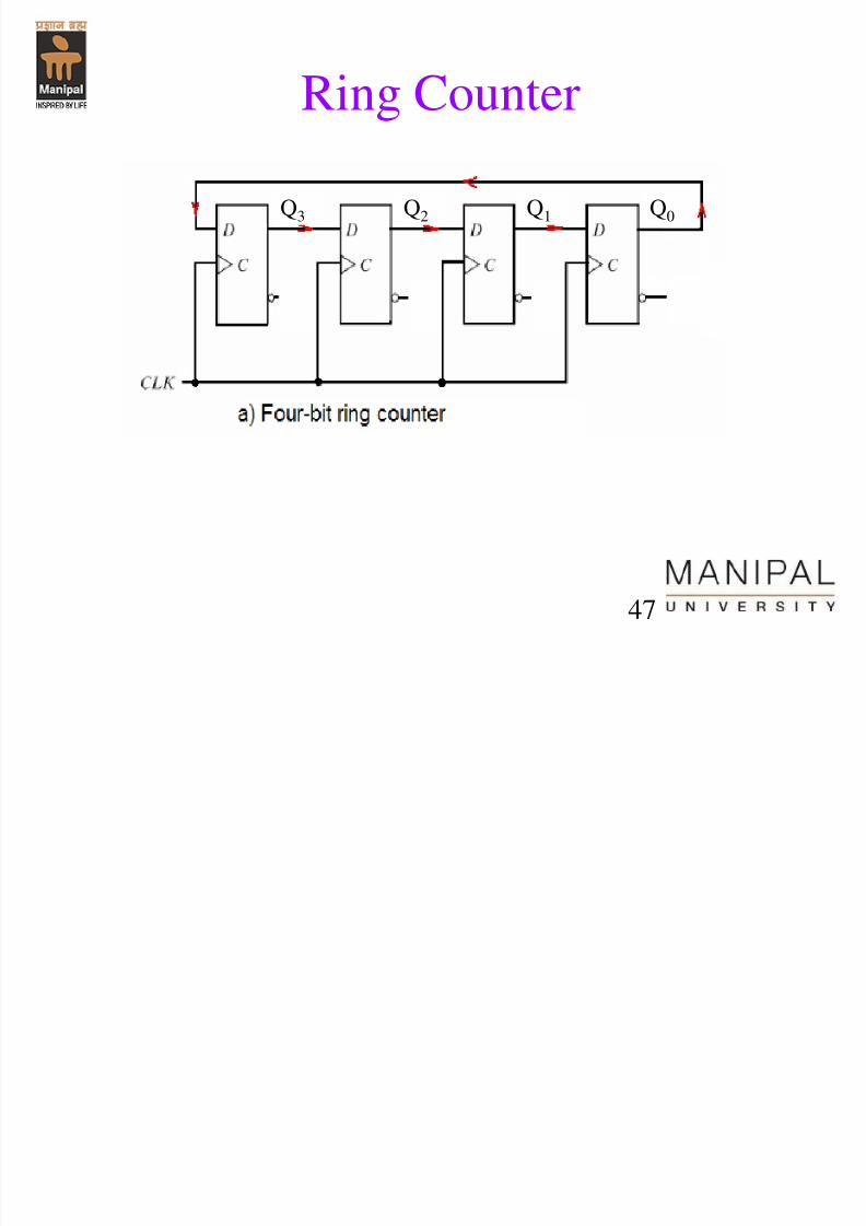
Ring Counter
Q3 Q2 Q1 Q0
7/31/2019 Counters Registers
http://slidepdf.com/reader/full/counters-registers 48/56
48
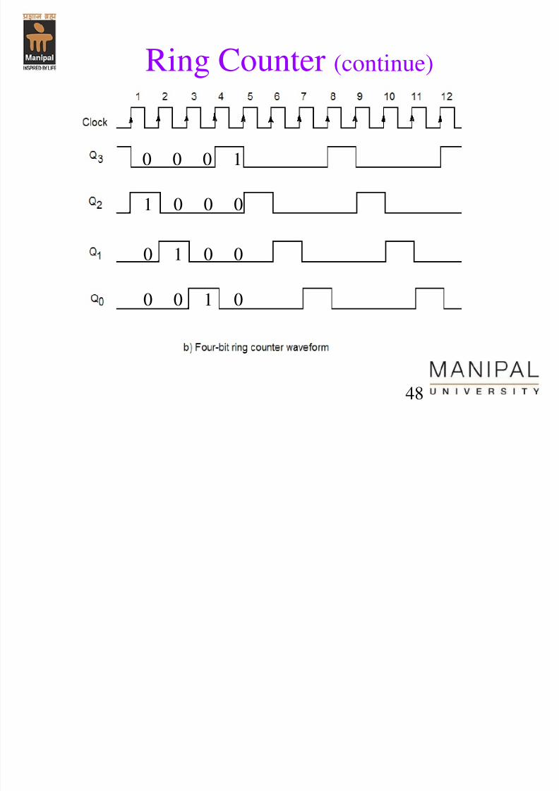
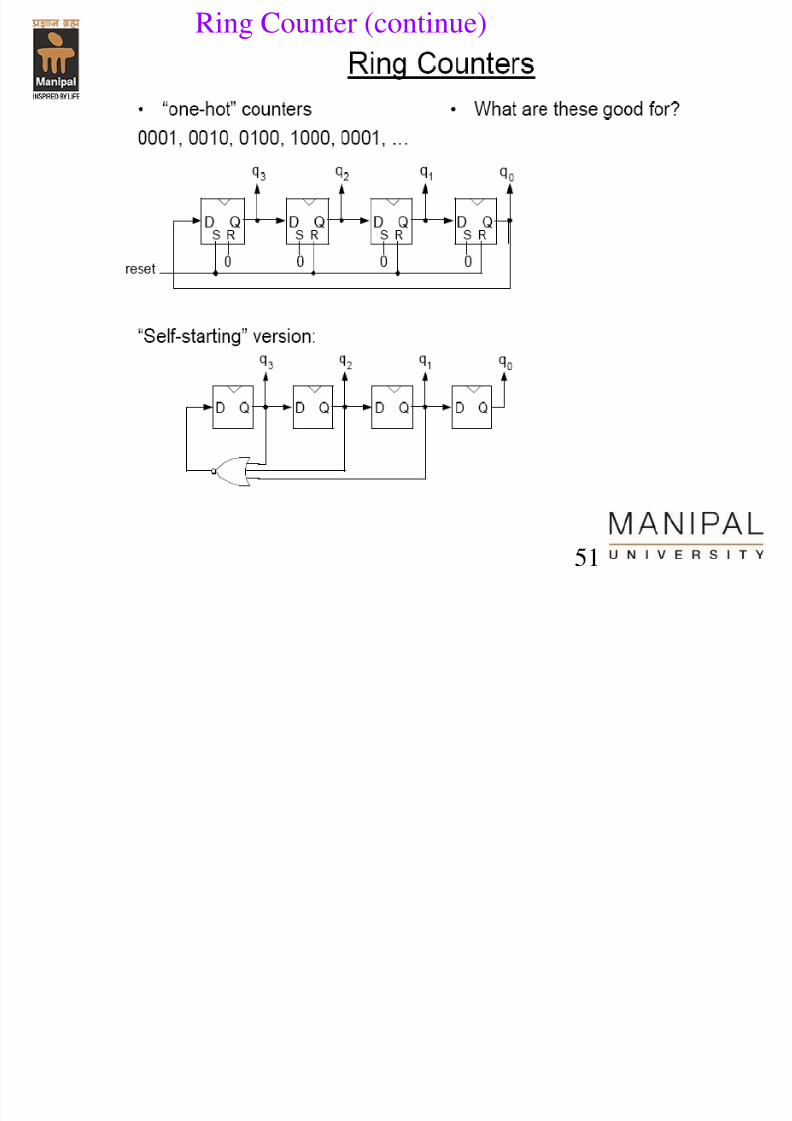
Ring Counter (continue)
0 0 0 1
1 0 0 0
0 1 0 0
0 0 1 0
7/31/2019 Counters Registers
http://slidepdf.com/reader/full/counters-registers 49/56
49
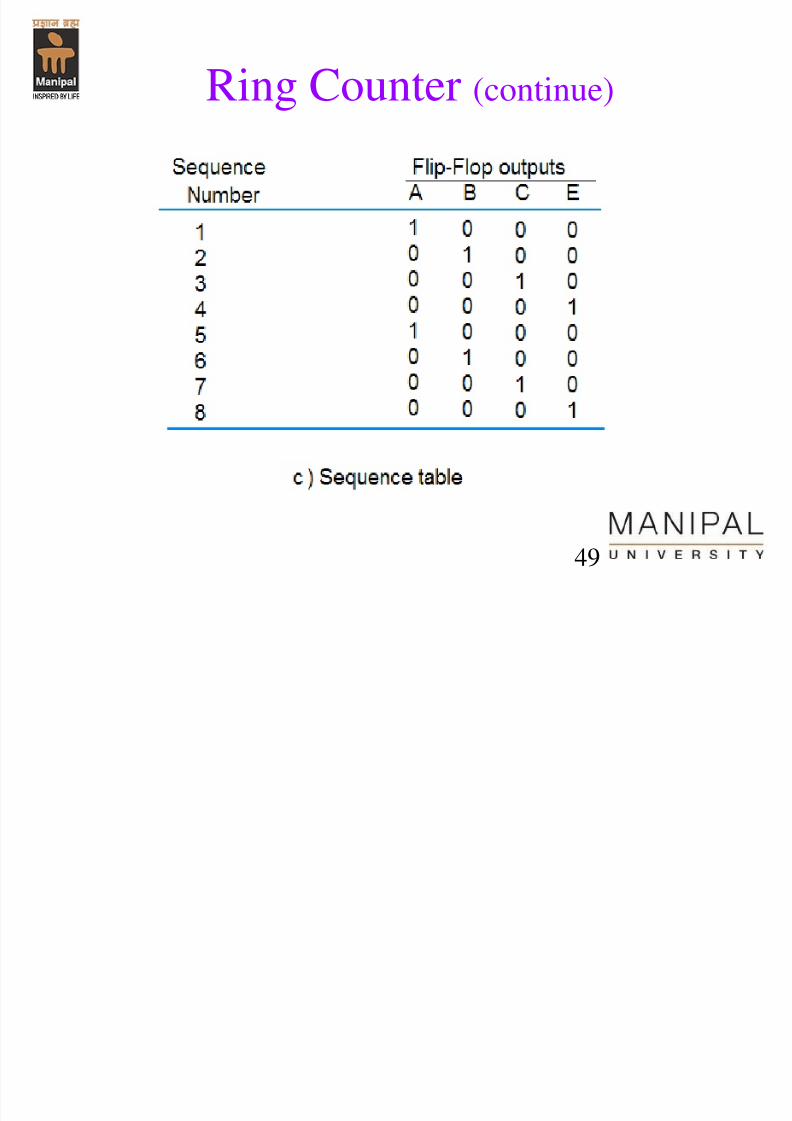
Ring Counter (continue)
7/31/2019 Counters Registers
http://slidepdf.com/reader/full/counters-registers 50/56
50
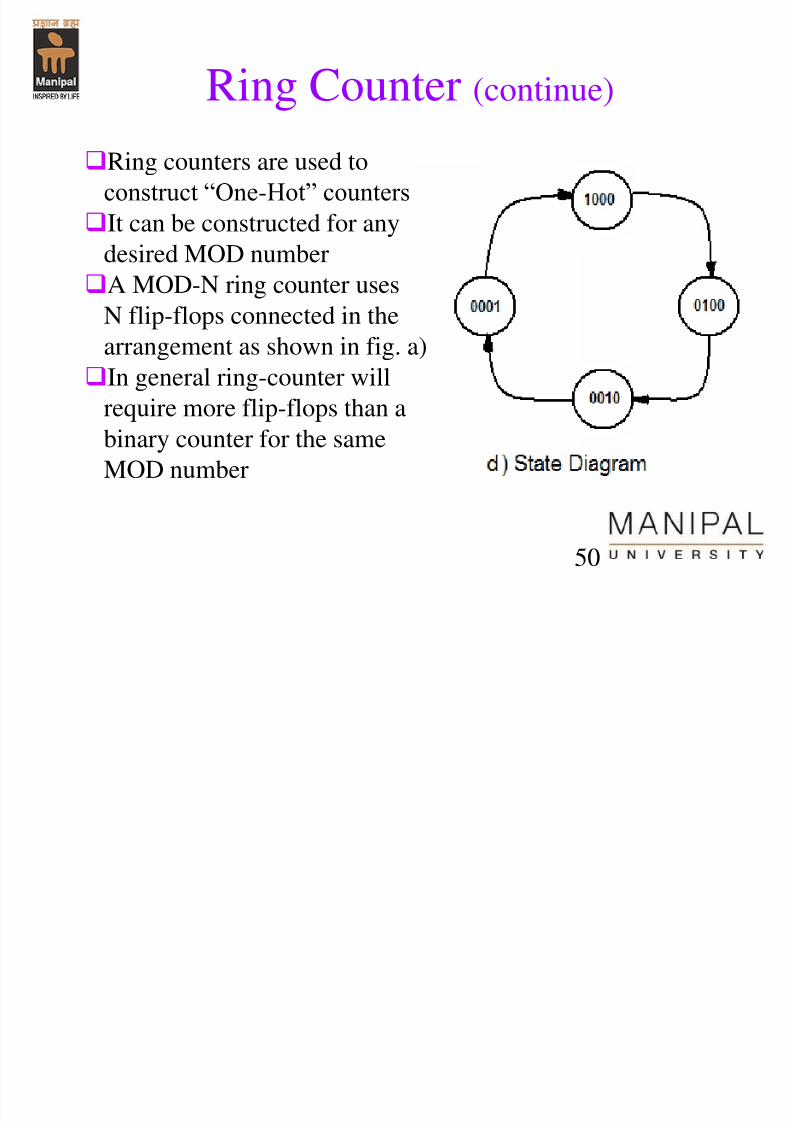
Ring Counter (continue)
Ring counters are used to
construct “One-Hot” counters
It can be constructed for any
desired MOD number
A MOD-N ring counter usesN flip-flops connected in the
arrangement as shown in fig. a)
In general ring-counter will
require more flip-flops than abinary counter for the same
MOD number
Ring Counter (continue)
7/31/2019 Counters Registers
http://slidepdf.com/reader/full/counters-registers 51/56
51
g ( )
7/31/2019 Counters Registers
http://slidepdf.com/reader/full/counters-registers 52/56
52
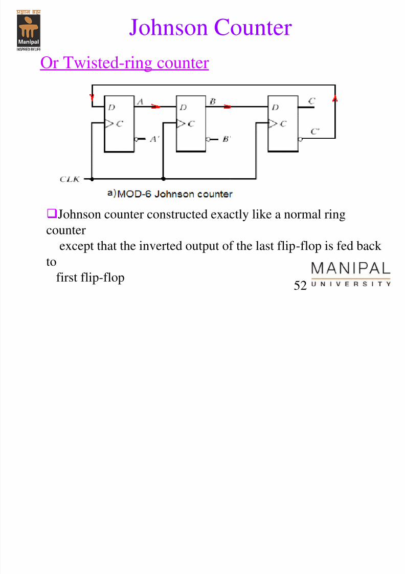
Johnson Counter
Or Twisted-ring counter
Johnson counter constructed exactly like a normal ringcounter
except that the inverted output of the last flip-flop is fed back
to
first flip-flop
h C
7/31/2019 Counters Registers
http://slidepdf.com/reader/full/counters-registers 53/56
53
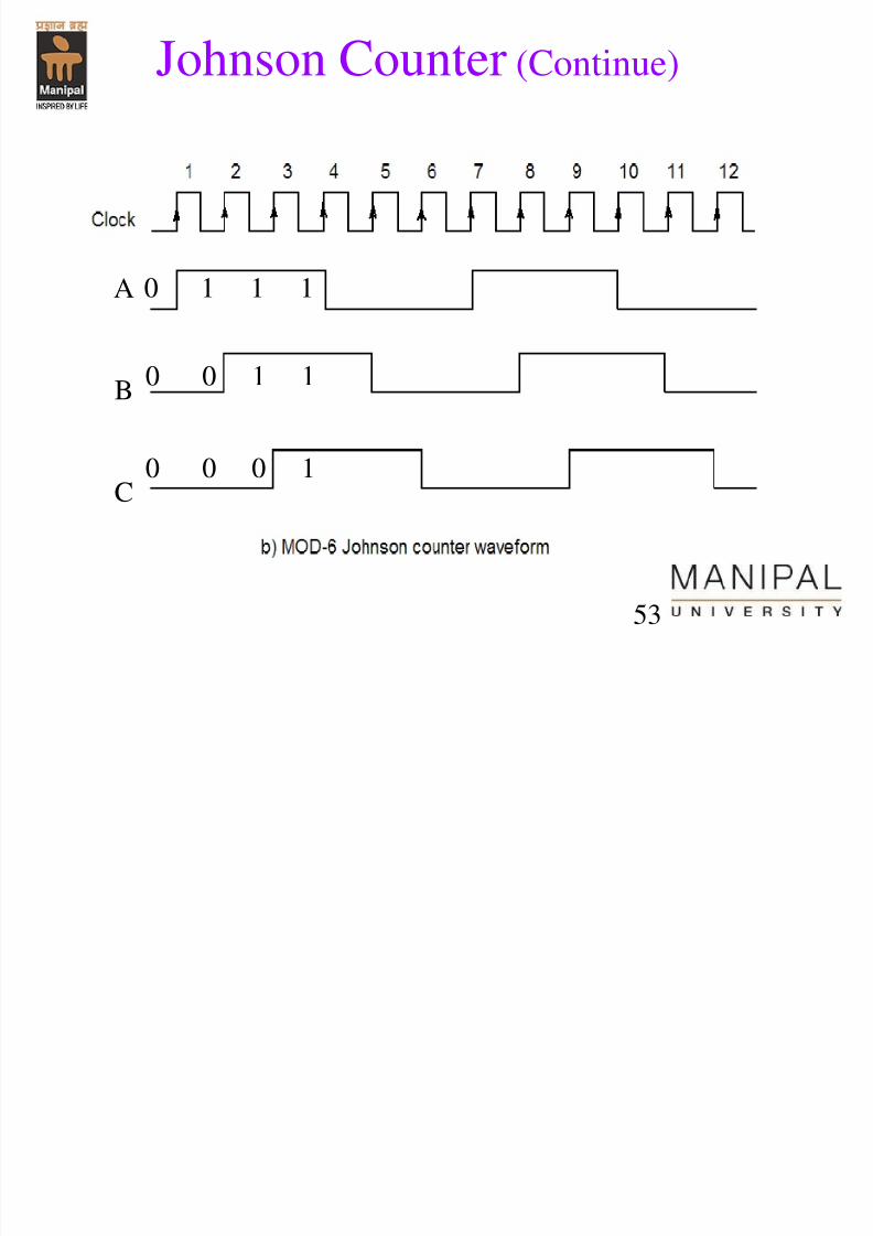
Johnson Counter (Continue)
A
B
C
0 1 1 1
0 0 1 1
0 0 0 1
J h C
7/31/2019 Counters Registers
http://slidepdf.com/reader/full/counters-registers 54/56
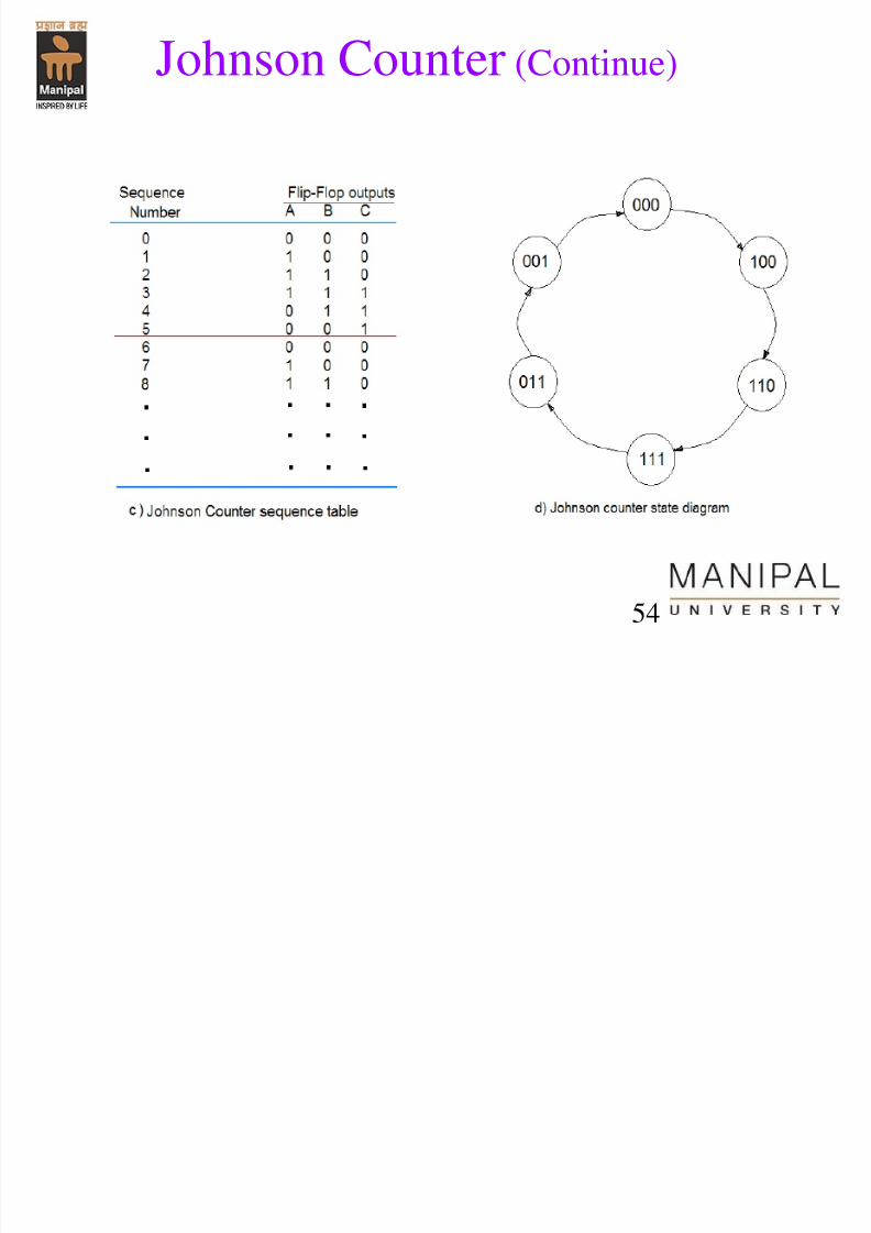
54
Johnson Counter (Continue)
7/31/2019 Counters Registers
http://slidepdf.com/reader/full/counters-registers 55/56
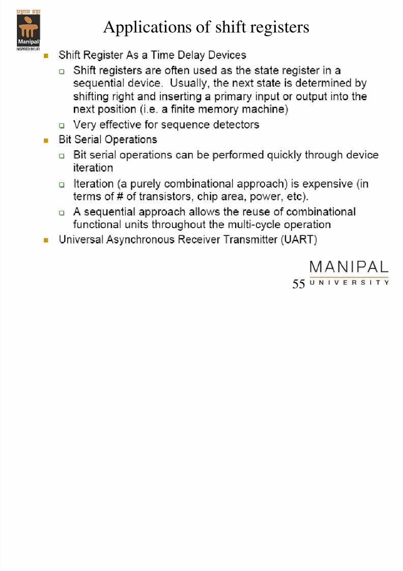
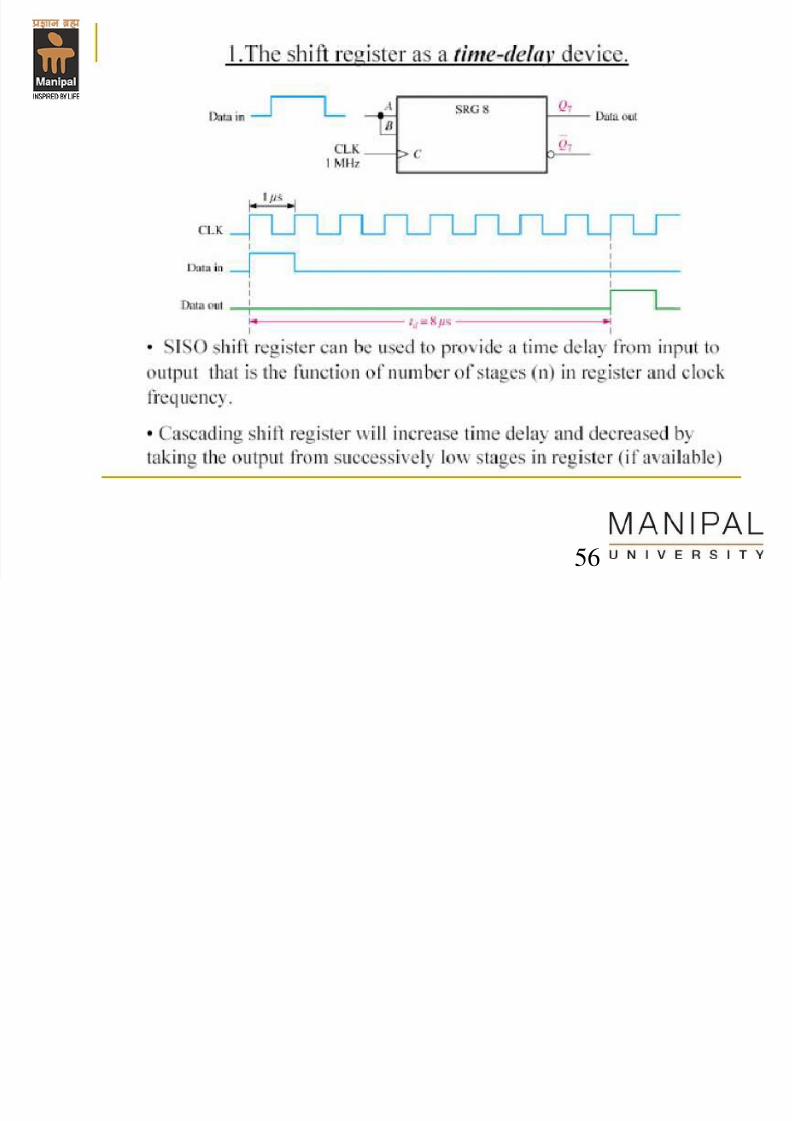
Applications of shift registers
55
7/31/2019 Counters Registers
http://slidepdf.com/reader/full/counters-registers 56/56
Applications of shift registers