county ground water studies 2 geology and ground …
TRANSCRIPT
NORTH DAKOTA GEOLOGICAL SURVEY
WILSON M. LAIRD, State Geologist
BULLETIN 4 1
NORTH DAKOTA STAT E
WATER CONSERVATION COMMISSION
MILO W. HOISVEEN, State Engineer
COUNTY GROUND WATER STUDIES 2
GEOLOGY AN DGROUND WATER RESOURCE S
of Stutsman County, North Dakot a
PART III
GROUND WATER AND ITS CHEMICAL QUALITY
By
C. J. HUXEL, JR . and L. R. PETRI
GEOLOGICAL SURVE Y
United States Department of the Interio r
Prepared by the United States Geological Surve yin cooperation with the North Dakota State Water Commission ,
North Dakota Geological Survey, and Stutsman County .
GRAND FORKS, NORTH DAKOT A
1965
This is one of a series of county reports
published cooperatively by the North Da-
kota Geological Survey and the North Da-
kota State Water Conservation Commission .
The reports are in three parts; Part I de-
scribes the geology, Part II presents ground
water basic data, and Part III describes th e
ground water resources. Parts I and II have
been published previously .
CONTENTS
Page
ABSTRACT 1
INTRODUCTION 2
Purpose and scope of investigation 2
Location and physiography 2
Previous investigations 4
Well-numbering and location system 4
Acknowledgements 4
WATER-BEARING CHARACTERISTICS OF THEGEOLOGIC UNITS 6
Cretaceous bedrock formations 6
Dakota Sandstone 6
Pierre Shale 9
Glacial drift 1 1
Glaciofluvial sediments 1 2
Valley outwash deposits 1 2
Jamestown aquifer 1 5
Plainview aquifer 1 7
Seven-mile Coulee aquifer 1 7
Unconfined outwash deposits 1 7
Marstonmoor Plain aquifer 20
Ice-contact deposits 22
Medina aquifer 23
Goldwin aquifer 23
Undifferentiated outwash deposits 23
Glaciolacustrine sediments 2 5
Buried glacioaqueous sediments 26
i
CONTENTS, Continued
Glacial drift (Cont.)
Page
Undifferentiated sand and gravel deposits 26
Eric Lake aquifer 2 9
Upper Buffalo Creek aquifers 29
Homer aquifer 2 9
Klose aquifer 2 9
Courtenay aquifer 3 2
Deer Lake aquifers 32
Streeter aquifer 3 2
Undifferentiated silt and clay deposits 32
Buried valley deposits 35
Spiritwood aquifer 35
Windsor aquifers 37
Midway aquifer 3 7
Mount Moriah aquifer 37
Sydney aquifer 37
Till
3 8
CHEMICAL QUALITY OF THE WATER 3 8
Water from Cretaceous bedrock 4 2
Water from Pleistocene drift 4 5
Suitability of the water for use 48
Municipal, domestic, and stock supply 48
Industry 5 2
Irrigation 5 4
SUMMARY 5 5
REFERENCES 5 7
ii
ILLUSTRATIONS
Page
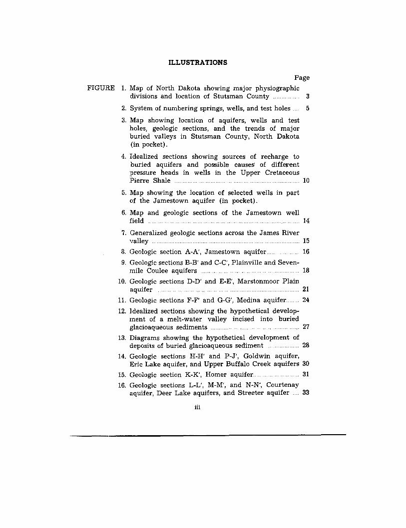
FIGU:RE 1 . Map of North Dakota showing major physiographicdivisions and location of Stutsman County 3
2. System of numbering springs, wells, and test holes 5
3. Map showing location of aquifers, wells and testholes, geologic sections, and the trends of majo rburied valleys in Stutsman County, North Dakota(in pocket) .
4. Idealized sections showing sources of recharge toburied aquifers and possible causes of differen tpressure heads in wells in the Upper Cretaceou s:Pierre Shale 1 0
5. Map showing the location of selected wells in par tof the Jamestown aquifer (in pocket) .
6. Map and geologic sections of the Jamestown wel lfield 14
7. Generalized geologic sections across the James Rive rvalley 1 5
8. Geologic section A-A', Jamestown aquifer 1 6
9. Geologic sections B-B' and C-C', Plainville and Seven -mile Coulee aquifers 1 8
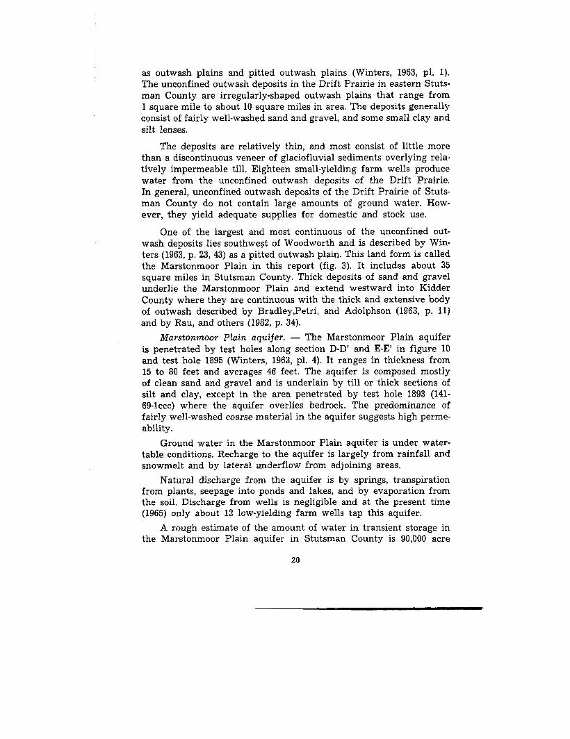
10. Geologic sections D-D' and E-E', Marstonmoor Plainaquifer 2 1
11. Geologic sections F-F' and G-G', Medina aquifer 24
12. idealized sections showing the hypothetical develop-ment of a melt-water valley incised into buriedglacioaqueous sediments 2 7
13. Diagrams showing the hypothetical development o fdeposits of buried glacioaqueous sediment 28
14. Geologic sections H-H' and P-J', Goldwin aquifer ,Eric Lake aquifer, and Upper Buffalo Creek aquifers 30
15. Geologic section K-K', Homer aquifer 3 1
16. Geologic sections L-L', M-M', and N-N', Courtenayaquifer, Deer Lake aquifers, and Streeter aquifer . . . . 33
iii
ILLUSTRATIONS, Continued
Page
17. Map and diagram showing relation between existingwells, test holes, and buried aquifers in the vicinityof Deer Lake township 3 4
18. Geologic sections P-P and Q-Q', Spiritwood aquifer 3 6
19. Geologic sections R-R', S-S', T-T' and U-U', Windsor ,Midway, Mount Moriah, and Sydney aquifers (inpocket) .
20. Map showing chemical-quality sampling sites 39
21. Percentages of the major constituents in water fro mCretaceous bedrock 42
22. Relation of major ions to dissolved solids in wate rfrom Pierre Shale 43
23. The percentages of the major constituents in waterfrom Pleistocene drift 44
24. Relations of major constituents to dissolved solids inwater from Pleistocene drift 47
TABLES
TABLE 1. Records of artesian wells in the Dakota Sandstonein Stutsman County 7
2. Stratigraphic units of the glacial drift and theirwater-bearing characteristics (in pocket) .
3. Public supply and industrial wells in the Jamestow naquifer 1 3
4. Results of aquifer tests performed on aquifers com-posed of glaciofluvial sediments 1 9
5. Chemical composition and physical characteristics o fthe ground water, Stutsman County 4 0
6. Relation of the quality of water in Stutsman Countyto drinking-water standards of the U. S. PublicHealth Service 49
iv
Geology and Ground Water Resources o f
Stutsman County, North Dakot a
Part 111—Ground Water and its Chemical QualityBy
C. J . Huxel, Jr. and L. R. Petri
ABSTRACT
Stutsman County comprises an area of about 2,300 square milesin south-central North Dakota . The western part of the county is i nthe Coteau du Missouri, a part of the Missouri Plateau section of th eGreat Plains physiographic province ; the eastern part is in the Drif tPrairie section of the Central Lowlands province . The Missouri Coteauescarpment forms a boundary separating the two physiographic divi-sions .
Most of the ground water is developed from : (1) the Cretaceou sbedrock formations, the Dakota Sandstone and the Pierre Shale, an d(2) the overlying Pleistocene glacial drift . Permable deposits of thedrift furnish the most readily available and largest supplies of groundwater and small quantities of ground water are available from th ebedrock formations .
The drift consists of exposed glaciofluvial and glaciolacustrin esediments, buried glacioaqueous sediments, and till .
The Jamestown, Marstonmoor Plain, and the Spiritwood are th emajor aquifers in the glacial drift . The Jamestown aquifer consist sof surficial outwash in the valley of the James River . It is extensivelydeveloped in the vicinity of Jamestown . The Marstonmoor Plainaquifer consists of surfical outwash that underlies a pitted plain . TheSpiritwood aquifer consists of glacioaqueous sediments in a larg eburied valley . The Marstonmoor Plain and the Spiritwood aquifer sare not extensively developed .
Most wells in the county are used to supply water for domesti cor stock-watering needs. Most of the ground water. is of relativel ypoor quality for domestic, municipal, or industrial uses . However ,water from surficial sand and gravel deposits can be treated to softe nit and to remove iron and manganese from it so that it is acceptabl efor most uses .
1
INTRODUCTIO N
Purpose and Scope of Investigatio n
The development of water supplies of suitable quality and quan-tity for municipal, industrial, and agricultural purposes has long beena major problem in North Dakota . This problem has become acut ein the past decade because of urbanization; industrial development ,even on a moderate scale ; and a growing interest in irrigation withground water . Recognizing that information on the water resource sof Stutsman County was in serious deficit, the Board of CountyCommissioners of Stutsman County and the city officials of James -town requested the U. S. Geological Survey, North Dakota StateWater Commission, and the North Dakota Geological Survey t omake an investigation of the geology and ground-water resources ofthe county. Thus the purpose of this report is to define and describ ethe geohydrologic character of the major water-bearing deposit sdiscovered or better understood as a result of the investigation .
The investigation of the geology and ground-water resource sof the county was begun in 1958 and included the following work :(1) assembling and evaluating water data from about 2,000 wells ;(2) geologic mapping of the surficial deposits ; (3) drilling 200 testholes to determine the extent of the known water-bearing rocks an dlocating previously unknown water-bearing rocks ; (4) determiningthe hydrologic characteristics of the water-bearing rocks ; (5) deter-mining the chemical quality of ground water ; and (6) preparin gthree reports of the results of the investigation .
The results of the investigation are described in a geology repor tby H. A. Winters (1963), a basic-data report by Huxel and Petri(1963), and this report on the ground-water resources of the county .
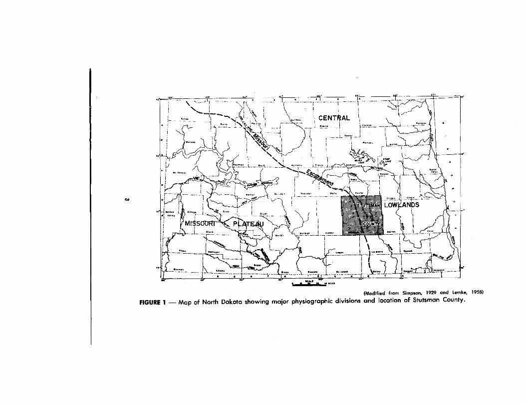
Location and PhysiographyStutsman County is in south-central North Dakota and comprises
approximately 2,300 square miles . Stutsman County is divided intotwo major physiographic divisions (fig . 1) . The western part of thecounty is in that part of the Missouri Plateau known as the Coteau duMissouri, an area characterized by lakes and marshes and an absenc eof integrated drainage. Most of the lakes and marshes are locallycalled "prairie potholes . " The eastern part of the county is within th eDrift Prairie of the Central Lowlands province . This area is gentl y
2
.00• •! C
— —,, .
N L..
-n CENTO AL .1 0000 0
i
i
\
i
i
-j--,
.
0 0000 0\S.%
L
t.
i
i
• 00 0000.0
!f!'Lrt .
_
0, Loani
Lr-
i
000400
0,011 0r L _
,i
00
00000
▪ Vell•o i
I
(Modified from Simpson, 1929 and Lemke, 1958 )
FIGURE 1 — Map of North Dakota showing major physiographic divisions and location of Stutsman County .
rolling with many lakes and marshes and a youthful drainage system .The James River and its tributary Pipestem Creek have cut deep ,wide valleys. In addition, the Drift Prairie has also been cut by man yshallow, irregular, winding coulees . The two major physiographi cdivisions in the county are divided by the Missouri Coteau escarp-ment, which trends north-northwest through the central part of th ecounty .
Previous Investigation sThe geology and ground-water resources of the Jamestown an d
Tower quadrangles have been described by Willard (1909) . Simpson(1929, p . 230-236) gave a general summary of the ground-water re-sources of Stutsman County . A report by Abbott and Voedisch (1939,p. 78-81) lists chemical analyses of water from 18 wells in StutsmanCounty. Well inventory records by the Works Progress Administra-tion and the North Dakota Geological Survey (unpublished records )include data that have been used in defining aquifers described inthis report. Wenzel and Sand (1942) described the water-bearin gcharacteristics of the Dakota Sandstone in part of Stutsman County .Adolphson (1961) and Dennis (1948) described the municipal watersupplies at Gackle and Wimbledon, respectively . Paulson's repor t(1962) on ground water in North Dakota is an excellent source o finformation on the occurrence of ground water in glacial drift .
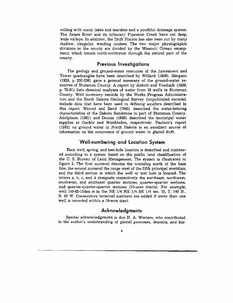
Well-numbering and Location Syste m
Each well, spring, and test-hole location is described and number-ed according to a system based on the public land classification o fthe U. S. Bureau of Land Management. The system is illustrated i nfigure 2. The first numeral denotes the township north of the bas eline, the second numeral the range west of the fifth principal meridian ,and the third section in which the well or test hole is located . Theletters a, b, c, and d designate respectively the northeast, northwest ,southwest, and southeast quarter sections, quarter-quarter sections ,and quarter-quarter-quarter sections (10-acre tracts) . For example,well 140-62-15daa is in the NE 1/4 NE 1/4 SE 1/4 sec . 15, T. 140 N . ,R. 62 W. Consecutive terminal numbers are added if more than on ewell is recorded within a 10-acre tract .
AcknowledgmentsSpecial acknowledgement is due H. A. Winters, who contributed
to the author 's understanding of glacial processes, deposits, and his -
4
tory of Stutsman County. He also added valuable criticisms an dsuggestions in review of this report . Appreciation is also expressedfor the information and help from well drillers and from the munici-pal and county officials .
WATER-BEARING CHARACTERISTICS OF THE
GEOLOGIC UNITS
The earth materials of Stutsman County that are significant i nthe development of ground-water supplies can be divided into tw ostratigraphic categories : (1) the Cretaceous bedrock formations an d(2) the Pleistocene glacial-drift deposits .
The Cretaceous bedrock formations are overlain unconformabl yby glacial drift in most areas . The bedrock formations that yiel dground water in the county are the Dakota Sandstone and the UpperCretaceous Pierre Shale . However, the permeable deposits of theglacial drift yield more water . The locations of some of the majoraquifers in the drift are shown on figure 3 . The limited scope of th einvestigation did not allow the definition of all aquifers in the County .Glacial-drift deposits are generally not uniform and test drilling i sdesirable to find a suitable production-well location . The aquifer sthat are shown on figure 3 generally may be expected to yield watersupplies, but the illustration is not intended for the selection ofspecific well sites . In addition to figure 3 the reader is referred t oplate 4 of Winter 's report (1963) for more detailed information con-cerning subsurface drift deposits .
Cretaceous Bedrock Formation sDAKOTA SANDSTON E
The Dakota artesian basin in North Dakota was first described inthe late 19th century and a complete list of publications through 193 9relating to the basin in North Dakota is given by Wenzel and Sand(1942, p . 11) . The Dakota Sandstone has been used as a source ofartesian water since the 1880's . Although it continues to supply wate rto flowing wells in much of South Dakota and eastern North Dakota ,it is not widely used in Stutsman County owing to the excessivedepth of the formation and poor quality of water . Records of 17 wellsthat draw or did draw water from the Dakota Sandstone in Stutsma nCounty are available (table 1) .
6
TABLE 1 . — Records of artesian wells in the Dakota Sandstone in Stutsman County .
Location
SourceDepth
Owner
(feet)
Use oregnd0ion
(1964)
Datele!ed
Chemica lPre : : :
analysiswater level
availabl e(feet)
(table 5 )
137-62-12d
3
137-63-21b
2
137-63-21d
3
138-62-24c
1
138-63-1c
1, 3
138-63-4c
2
138-63-9bca
4
138-66-24dda 4
139-63-5a
2
139-63-6
2
139-63-6cba 1,2,4
139-63-17a
3
140-63-24bcd 4
140-63-25
1, 2
140-63-25c
2, 3
140-63-25ccc 1,2,4
144-66-2abb
4
Union Central Life Ins. Co . 1 ,485
F. Lee
1,300
M. Lee
1,60 0
1,380
E. Steege
1,480
S. F. Corwin
1,35 8
1,350
A. Glinz
1,98 0
Dakota Meat Company
1,51 0
Jamestown State Hospital 1,536
do
1,524
Federal Land Bank
1,46 0
H. Tahran
1,57 2
City of Jamestown
1,57 0
Western Electric Company 1,490
City of Jamestown
1,476
R. F. Reimer
1,934
Destroyed
do
do
do
+20
do
do
Existing
do
Destroyed
do
Existing
Destroyed
Existing
Destroyed
-I-
do
Existing
do
Before 192 7
Before 192 0
Before 1937
Before 190 9
do
Before 1920
190 0
1962
Before 192 0
do
189 0
Before 1937
196 1
Before 1909
Before 192 0
188 7
1959
Flow
-50
Flow
Yes
Flow
Yes
Yes
Flow
Yes
-4
Yes
Yes
Yes
Source :1. Willard, 19092. Simpson, 19293. Wenzel and Sand, 19424. Huxel and Petri, 1963
In Stutsman County the Dakota Sandstone is overlain by younge rCretaceous formations, which consist mainly of shale. The top of thesandstone was penetrated by oil-test wells at depths ranging fromabout 1,250 feet in the eastern part of the county to 2,250 feet nea rthe western edge; it dips to the west at about 5 to 10 feet per mil e(Winters, 1963, p. 14) .
The Dakota Sandstone is described as layers and (or) lenses o ffriable sandstone interbedded with layers of clay and shale (Simpson ,1929, p . 40-41) . Hopkins and Petri (1963, p . 22) estimate that thelayers and lenses of sandstone constitute only about one-fourth t oone-fifth the total thickness of the formation. On the basis of oil-testwell logs, Hansen (1955, p . 17-29) describes the Dakota Sandstone inNorth Dakota as consisting of a group of formations called the Dakot a
Group. However, the well-established name Dakota Sandstone i sused in this report.
In Stutsman County, as in most of North Dakota, the water of theDakota Sandstone has been reported to flow from several intervals .These are called artesian flows (Wenzel and Sand, 1942, p . 15) . Willard(1909, p . 9) reported three flows and stated that the pressure an dchemical quality characteristics of each were different . Hard (1929 ,p. 49) reported that seven successive flows had been penetrated i n
drilling a single well . The flows are separated by shale or dens esandstone. Concerning differentiations of flow intervals, Wenzel an d
Sand (1942, p . 15) have stated : The chemical character of the wate r
probably provides as good a basis as any for differentiating betwee nthe several flow horizons . The water from the upper part of the sand -stone is generally soft but somewhat salty and is often assigned to the
`first flow' . The waters from the sandstone at greater depths areusually much harder but lower in chloride and are commonly regarde das `second flow' waters. However, a water of very high mineral con-tent but apparently of no consistent chemical character is encountere din some places in the deepest sandstone beds ; it is designated by somedrillers as `third flow' water."
Artesian pressure in the Dakota Sandstone and yields of wellstapping it began to decline immediately after the first wells wer e
developed in 1886 and have declined ever since . As a result, the area
of artesian flow in North Dakota has decreased accordingly . Wenzel
and Sand (1942, p. 31-38) present a summary of these changes through
1939 .
Since 1959, only three wells have been reported drilled to the
Dakota Sandstone in Stutsman County. It is likely, however, that
8
other wells will be drilled to the Dakota, especially in areas wheredrift aquifers are either absent or furnish inadequate supplies . Be-cause of its great depth and the poor quality of its water, however,it is unlikely that the Dakota Sandstone will be used as a majorsource of supply, at least in the foreseeable future.
PIERRE SHAL E
A thick section of predominantly shale underlies the Pierre Shal eand overlies the Dakota Sandstone (Winters, 1963, p . 11) . The shalesequence functions mainly as a confining bed on the Dakota Sand -stone. The Pierre Shale directly underlies glacial drift everywherein the county except in a few places where it is exposed (Winters ,1963, p . 12), where it was removed by erosion in pre-glacial valley s(test hole 1874, 143-62-11aba), and in the southwestern part of thecounty where it is overlain by the Upper Cretaceous Fox Hills Sand-stone Y (Huxel and Petri, 1963, table 2, test holes 1906 and 1907) . Out-crops of Pierre Shale are most abundant along parts of the Jame sRiver and Beaver Creek valleys (Winters, 1963, p . 12) .
Subsurface samples from Stutsman County indicate that th ePierre Shale is gray to dark-greenish-gray, dense, usually brittle ,noncalcareous shale . No sandy layers were penetrated in any of thetest holes drilled into the formation in the county . In this reportthe various members making up the Pierre Shale are not differentia-ted and it is considered as a single geologic unit .
The fine texture and the relatively impermeable nature of thePierre Shale suggest that the formation would not serve as anaquifer ; despite this, however, many wells yielding adequate wate rsupplies for domestic and stock uses are finished in the upper par tof the shale in Stutsman County .
Pierre Shale is in places extremely fractured and jointed, thu spermitting ground water to move along the planes of the fractures an djoints and to provide water to wells penetrating the shale . Thepressure head of the ground water in the shale differs at differentlocalities — probably for reasons illustrated in figure 4, section B .Well 2 is finished in a fractured zone that is hydraulically connectedto permeable zones in the drift (till with sand and gravel layers, silt ,sand and gravel) . The permeable zones in the drift are hydraulicallyconnected to a source of recharge at the surface (the lake) . Well 2has a high pressure head. Well 1 is finished in a fractured zone ofthe shale that is buried by relatively impermeable till . Although the
9
(A )
wel l
~~
(I )i
(2)
La
. err
\\\\\\\\\\\\\\\\\\\\\\\\\\\\\XX .\\\\\\\\\\\\\(B )
(C )
EXPLANATIO N
Silt Sand andgrave l
'I ` IArrow Indicate
Til ldirection o f
ground-Totermovement
Curved arrowsindicate aatremey
star rate of mowmeel .
Till olthBond an d
gravel layers
.tlnfraehred
FracturedPierre Shale
Pierre Shal e
Figure 4 — Idealized sections showing sources of recharge to buriedaquifers and possible causes of different pressure head i nwells in the upper Cretaceous Pierre Shale .
I0

fractured zone receives small amounts of recharge through the till, i thas no effective hydraulic connection with surface sources of recharg eor with more permeable zones in the drift . Therefore, the pressurehead in well 1 is low .
Glacial Drif tSediments deposited directly or indirectly as a result of glaciatio n
may be referred to as glacial drift. Drift covers all of Stutsman Countyexcept along the bluffs of the James River and other major strea mvalleys where it has been removed by erosion . Throughout much o fthe county the drift is more than 100 feet thick and in some place sis as much as 500 feet thick. The materials of the drift range fro mclay-size particles to large boulders .
The drift may be divided into sediment types and geohydrologicunits on the basis of : (1) lithology, (2) mode of origin, (3) associationwith particular landforms, and (or) '(4) water-bearing characteristics(table 2). Three major geohydrologic units are recognized in the coun-ty; two of these consist of glacioaqueous materials and the third i sglacial till. The till was deposited directly by glacial ice with littl eor no modification by wind or water and consists of approximatel yequal portions of clay, silt, and sand, with minor amounts of large rparticles. Glacioaqueous is a genetic term describing materials tha thave been deposited from glacial melt water . The three major typesof glacioaqueous sediments recognized in the county are : (1) surficialglaciofluvial sediments, (2) surficial glaciolacustrine sediments, and(3) buried glacioaqueous sediments . The term buried glacioaqueoussediments as used in this report refers to deposits of both glaciofluvia land glaciolacustrine origin that are buried by till or are overlain b ysurficial glaciiofluvial or glaciolacustrine sediments .
Ground-water recharge to glacial sediments in Stutsman Count yis derived from direct infiltration of precipitation, infiltration fromstreams and lakes, underflow from sediments in adjacent areas, andupward percolation from underlying sediments. A major factor thataffects the amount of recharge in any area is the permeability of th eunderlying materials . Other important factors include the nature ofthe topography, the type and profusion of vegetation, and climaticconditions . Glaciofluvial sediments readily accept surface rechargebecause of the high permeability of these materials . Till or glacio-lacustrine sediments accept surface recharge at a much lower rat ebecause these sediments are less permeable .
In general, buried glacioaqueous sediments are isolated from the
11
surface by intervening relatively impermeable till and, thus, receiv erecharge from infiltration of precipitation at extremely low rates.However, where these deposits are contiguous with more permeabl edeposits that have access to infiltrating precipitation, the rate of re-charge resulting from underflow may be large . An example of suchrecharge is shown by arrows in figure 4 B .
The rate at which ground water moves through a rock unit de-pends on the permeability of the unit and the hydraulic gradient .Permeabilities of the various deposits of the glacial drift in Stutsma nCounty are classified into the categories of very low, low, moderate ,and high. The four categories are arbitrary qualitative estimates base don the texture and modifying texture of the materials making upthe deposits and on the observed performance of wells penetratingthem. Deposits with very low permeability permit only a negligibl eamount of ground-water movement through them and function es-sentially as "permeable confining beds" (Meinzer, 1923, p . 40). De-posits that are too fine-grained to function as aquifers but that ar ecoarse enough to permit appreciable ground-water movement ar eclassified as low in permeability and can function as avenues of re -charge to the aquifers with which they are connected. Deposits classi-fied as moderate or high in permeability are sufficiently coarse t ofunction as good aquifers .
Discharge of ground water from saturated glacial sediments takesplace by seepage into springs, lakes, marshes, and streams ; by evapo-transpiration ; by flow or withdrawal from wells ; and by underflowinto adjacent areas .
GLACIOFLUVIAL SEDIMENTS
Glaciofluvial sediments in Stutsman County are classified intofour types of deposits — valley outwash, unconfined outwash, ice -contact deposits, and undifferentiated outwash. These deposits aremappable, surficial units and are called geohydrologic units in thisreport . (See table 2 .) Winters (1963, p . 22-23, 75-76) has discussed thelithology and landforms of surficial glaciofluvial sediments in detail .
Valley Outwash Deposit s
Valley outwash deposits consist of glaciofluvial sediments thatwere deposited in valleys . They include the units defined by Winters(1963, pl . 1) as valley outwash, erosional terraces other than thos ecomposed of till, pitted valley outwash, and kame terraces. In gen-eral, valley outwash deposits are continuous in the drainage system
12
TABLE 3. — Public supply and industrial wells in the Jamestown aquifer .
vro : B, ---_ ; Or , drilled ; un_ 49H_ Uwe of Toter : Ind, induatrial ; PO, public supply ;Pe (a), auxiliary public supply ; U, .wind .
Diameter
Depth to .
Length
UseDepth of well or 'is* Type
Date
voter
of
of
Nlevation of
nett
(feet) -limbos)
completed
(feet below screen water land surfac e1"nd surface)
Owner or name
2 . Midland Continental Railroad
2. Northern Pacific Railroad
3. Fargo Iron and Metal Co . (No . 1 )
4. Fargo Iron and Metal Co . (No . 2 )
5. Ottertail Power Co .
6. Bridgman-Russell Creamery (No . 1 )
7. Bridgeaan-Russell, Creamery (No . 2 )
8. Equity Union Creamery
9. City of Jamestown (No . 1 )
10. City of Jamestown (No . 2 )
11. City of Jamestown (No . 3 )
12. City of Jamestown (Jo . 4 )
13. City of Jamestown (No . 5 )
14. City of Jamestown (No . 6)
15. City of Jamestown . (No . 7)
16. City of Jamestown (No . 8)
17. City of Jamestown (PS 1 )
18. City of Jamestown (PS 2 )
19. City of Jamestown (PS 3 )
20. City of Jamestown (PS 4 )
21. Jamestown State Nast& .(Nn. 1)"
22. Jamestown State Hospital (Bo . 2 )
23. Jamestown State Hospital (Bo . 3)
48
36 - 72
B
1912
42
99
12
Dr
. . . .
1 3
214
1940
24
194 4
98
16
Dr
1949
26
30
96
Du
1920
24
90
8
Dr
1932
20
22
72
Du
1932
18
85
12
Dr
1909
12
87
10
Dr
1909
12
84
10
Dr
1909
12
85
10
Dr
1909
12
8o
16
Dr
1925
1 3
80
16
Dr
1928
36
300
Du
1929
57
300
Du
1958
14 .18
82 .5
16
Dr
1960
10. 5
87
16
Dr
1960
8 . 7
90
16
Dr
1960
8 . 6
104
16
Dr
1960
12 . 2
40
192
Du
. . . .
20
58
8
Dr
1944
13 .62
50
240
Du
1951
31 .42
Ind, U
1,420
48,000 gpd .
Ind, U
1,400
600,000 gpd .
Ind, U
1,405
8,000 gpd.
Ind, U
1,405
16,000 gpd .
Ind
1,410
60,000 - 100,000 gp4.
• Ind, U 1,410 60,000 gpd .
Ind, U
1,410
. .00. . . .
• Ind, U 1,400 10,000 gpd .
PS (a)
1,395
300 cm .
PS (a)
1,395
. .Do . . . .
PS (a)
1,395
. .DO . . . .
PB (a)
1,395
. .DO . . . .
PB (a)
1,395
500 SM .
PS (a)
1,395
PS (a)
1,395
1,400 gpm .
PS (a)
1,395
PS
1,390
3 - 5 mgd.
PS
1,390
. .Do . . . .
P8
1,390
. .00 . . . .
PB
1,390
. .00 . . . .
U 1,385
U 1,385
P8
1,385
260,000 gpd .
SCAL E250 Its
0
2tw
500 F.. t
EXPLANATIO N
Flll
oil
0raeay cloy
Send odd . . . . I
BEIClay
Sand
Clepy send and grave l
send, clay
0127 .2 tend
Boold .rs
scALE100 200 0 40F. . t
EXPLANATIONt
G v
Public supply wel land test-hole site
Test-hole site
e e sObservation well
A tlA'
Location of geologic sectio n
Boundary of Jamestown well field
of the Drift Prairie section of Stutsman County . Valley outwashdeposits consist of clean to clayey sand and gravel with intercalate dbeds of silt and clay. The sediments are known to be more than 130feet thick and to overlie older drift or bedrock. The valley outwashdeposits are locally overlain by Recent alluvium or colluvim .
Data from 91 wells in the valley outwash deposits of Stutsma nCounty were collected during this investigation . Most of the well shave small yields, generally less than 10 gpm, and are used for domes-tic and stock needs . Some have relatively high yields, as much a s1,400 gpm, and are used for industrial and public supply. The valleyoutwash deposits are not areally extensive, but, in places, they hav ethe potential to yield substantial quantities of water to wells .
Jamestown aquifer . — Valley outwash deposits of the Jame sRiver valley and Pipestem Creek valley join at Jamestown and for mthe largest valley outwash aquifer in the county . The configurationof the Jamestown aquifers is shown on figure 3 . The largest waterusers in the county are the city of Jamestown, various industries in
EXPLANATION
--J2 •I19
iiAaI,,121/iAI
test hol e1500145014001350
130 0
1250 7(A )
(A) section at the site of the Jamestown dam (hosed on unpublishe dtest drilling data, U . S. Bureau or Reclamation) .
Pierre Shale o fLate Cretaceous age
;CAL(
wotoo 1100 loo 0
1100
.Po .a n
test holes
ft'..;~„r'rA~,fzw,u i'd 1500 —
= 1450A.%1400
°1350 .1300 J
a
i(8 )
(E) section 3.5 miles downstream from Jamestown (based on dat afrom Paulson, 1962).
FIGURE 7 — Generalized geologic sections across the James River valley .
15
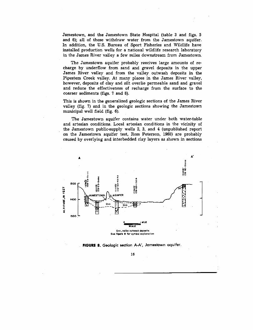
Jamestown, and the Jamestown State Hospital (table 3 and figs . 5and 6) ; all of these withdraw water from the Jamestown aquifer.In addition, the U .S. Bureau of Sport Fisheries and Wildlife haveinstalled production wells for a national wildlife research laborator yin the James River valley a few miles downstream from Jamestown .
The Jamestown aquifer probably reecives large amounts of re -charge by underflow from sand and gravel deposits in the uppe rJames River valley and from the valley outwash deposits in thePipestem Creek valley. At many places in the James River valley ,however, deposits of clay and silt overlie permeable sand and grave land reduce the effectiveness of recharge from the surface to thecoarser sediments (figs . 7 and 8) .
This is shown in the generalized geologic sections of the James Rivervalley (fig. 7) and in the geologic sections showing the Jamestownmunicipal well field (fig. 6) .
The Jamestown aquifer contains water under both water-tableand artesian conditions . Local artesian conditions in the vicinity ofthe Jamestown public-supply wells 2, 3, and 4 (unpublished repor ton the Jamestown aquifer test, Ross Peterson, 1960) are probabl ycaused by overlying and interbedded clay layers as shown in section s
a
°a
e1a
m'
a
aMM
lm
m °
iM0
bMM
MM
MalM M
JAMESTOWN
AQUIFER
vs'vs'M M
500
400
300
0
I MILESCALE
Qvo,valley outwash deposit sSee figure 9 for symbol explanatio n
FIGURE 8 . Geologic section A-A', Jamestown aquifer .
16
A-A" and B-B' (fig . 6) . Water-level and pumpage records have bee nkept on the public-supply wells and observation wells in the James -town municipal well field since their development in 1960 .
More water was withdrawn in 1963 from the Jamestown aquife rfrom any other aquifer in Stutsman County. Table 4 lists data onpublic and municipal wells that are now in use or have in the pas twithdrawn water from the aquifer . Most of the industrial wells i nthe Jamestown aquifer are no longer in use, but the Otter Tail PowerCompany well still produces between 0 .1 and 0 .2 mgd (million gallon sper day) during the summer (oral communication from officials ofOtter Tail Power Company) . The State Hospital has its own water-supply system and pumps about 0 .2 to 0.3 mgd from the Jamestownaquifer . Since 1960 an enlarged municipal water-supply system capa-ble of producing 5 mgd has been in operation and has furnishe dwater for most of Jamestown industrial and public facilities. Priorto 1960 the municipal water supply for the city was obtained fro m8 wells (table 3, fig . 5) with a combined daily rate of pumping o fover 2 mgd. In 1960 the city expanded production from the aquife rin the present municipal well field (fig . 6) . Aquifer tests of 18- to 24-hours duration were made on the Jamestown aquifer using each o f4 new wells . Table 4 summarizes the results of these tests .
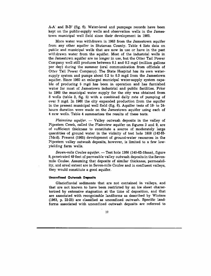
Plainview aquifer. — Valley outwash deposits in the valley o fPipestem Creek, called the Plainview aquifer on figures 3 and 9, areof sufficient thickness to constitute a source of moderately largequantities of ground water in the vicinity of test hole 1808 (142-65 -17dcd) . Present (1965) development of ground-water resources in th ePipestem valley outwash deposits, however, is limited to a few low -yielding farm wells .
Seven-mile Coulee aquifer . — Test hole 1366 (140-62-19aaa), figure9, penetrated 49 feet of permeable valley outwash deposits in the Seven-mile Coulee. Assuming that deposits of similar thickness, permeabil-ity, and areal extent are in Seven-mile Coulee and in confluent valleys ,they would constitute a good aquifer .
Unconfined Outwash Deposits
Glaciofluvial sediments that are not contained in valleys, an dthat are not known to have been restricted by an ice sheet charac-terized by extensive stagnation at the time of deposition, and tha tare associated with recognizable landforms as described by Winter s(1963, p . 22-23) are classified as unconfined outwash . Specific land-forms associated with unconfined outwash deposits are referred t o
17
B
B .
TILL
Til l
Til(all,
Gravel, clayey
Till, sandy
Gravel, portl ycemente d
Gravel, sandyand claye y
Till, gravelly
Graphic lithologic symbols
SAND
SILT AND CLAY
Sand
Silt
EXPLANATIONGRAVE L
InGravel
OTHER
Detrital lignite
Pierre Shale
Sand, clayey to silty
Clay
Boulder and a
Fox Hills Sandstonecobble concen-
Clay, silty
tranon
j l
Niobrarato sandy
Symbols :Qicl,
local ice-contact depositsQvo,
valley outwash depositsquo,
confined outwash depositsGive,
extensive ice-canton deposit sQug,
undifferentiated sand and gravel depositsGuc,
undifferentiated silt and cloy deposits, an dQvb,
buried valley deposits of Quaternary age .Qo,
undifferentiated outwash depositsAbbreviation s
B
Boulder
Sdy
Sandy
Lig
Detrital lignite
Gv
GravelCb
Cobble
Sty
Silty
Cent
Cemented
Sd
SandCI
Clay
Cly
Clayey
Ft
Feet
St
SiltCby
Cobbly
T
Till
DO
Depth of oxidation
WLESCAL E
1600
170 0
160 0
1500
Sand, portlycemented
Gravel, sand y
i iTill, cobbl y
Till with sandand gravel layer s
Figure 9 . Geologic sections B-B' and C-C', Plainview and Seven-mile Coule eaquifers .
18
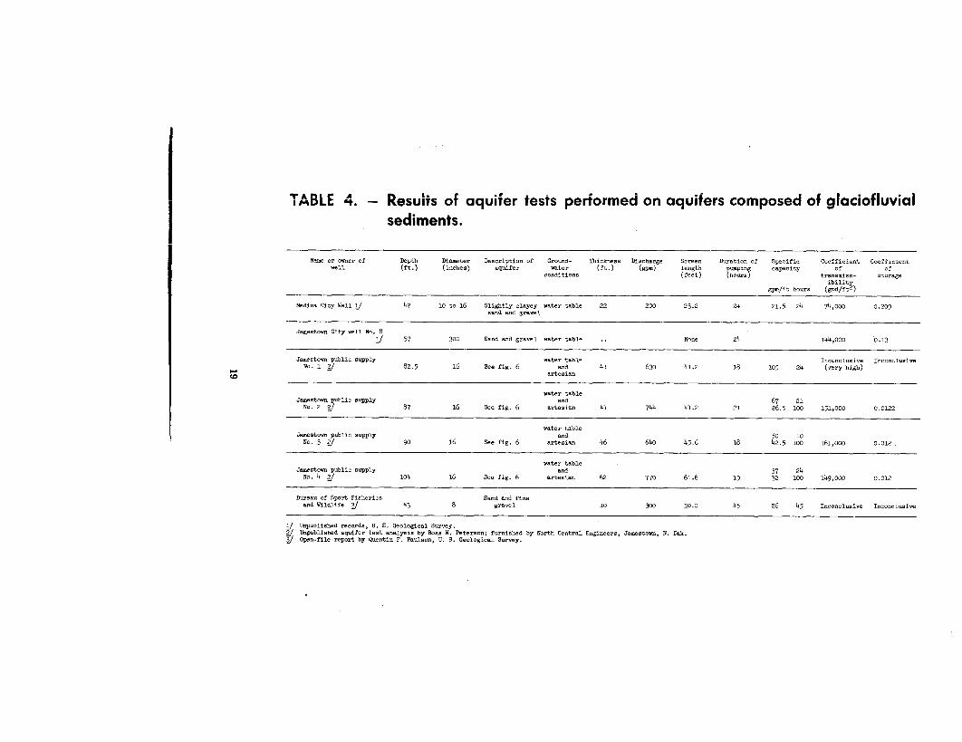
TABLE + . — Results of aquifer tests performed on aquifers composed of glaciofluvia lsediments.
Name or owner of
Depth
Diameter
Description of
Ground-
Thickness Discharge
Screen
Duration of
Specific
Coefficient Coefficientwell
(ft .)
(inches)
aquifer
water
(ft .)
(gym)
length
pumping
capacity
of
ofconditions
(feet)
(hours)
transmiss-
storageibility
gpm/ft hours
(gpd/ft2 )
Medina City Well J 42 10 to 16 Slightly clayey
water tablesand and gravel
22 200 23 .2 24 21 .5 24 74,000 0 .20 9
Jamestown City well No . 8
J 57 300 Sand and gravel water table None 24 144,000 0 .13
Jamestown public supplyNo . 1
2/ 82 .5 16 See fig . 6water table
andartesian
41 630 41 .2 18 105 24Inconclusive(very high)
Inconclusive
Jamestown public suppl yNo . 2
2/ 87 16 See fig . 6
water tableand
artesian 41 744 41 .2 216726 .5
2 1100 151,000 0 .012 2
Jamestown public supply90 16 See fig . 6
water tableand
artesian 46 640 45 .6 185042 .5
10100 161,000 0 .012 .No . 3
21
Jamestown public supply104 16 See fig . 6
water tableand
artesian 62 770 61 .6 193 732
24100 149,000 0 .01 2No . 4
2,
Bureau of Sport Fisheries
43 8Sand and fine
gravel 10 300 10 .0 45 26 45 Inconclusive Inconclusiveand Wildlife
J
1/ Unpublished records, U . S . Geological Survey .
J Unpublished aquifer test analysis by Ross W . Peterson ; furnished by North Central Engineers, Jamestown, N . Dak .2/ Open-file report by Quentin F . Paulson, U . S . Geological Survey.
as outwash plains and pitted outwash plains (Winters, 1963, pl . 1) .The unconfined outwash deposits in the Drift Prairie in eastern Stuts-man County are irregularly-shaped outwash plains that range fro m1 square mile to about 10 square miles in area . The deposits generallyconsist of fairly well-washed sand and gravel, and some small clay an dsilt lenses .
The deposits are relatively thin, and most consist of little mor ethan a discontinuous veneer of glaciofluvial sediments overlying rela-tively impermeable till . Eighteen small-yielding farm wells producewater from the unconfined outwash deposits of the Drift Prairie .In general, unconfined outwash deposits of the Drift Prairie of Stuts-man County do not contain large amounts of ground water . How -ever, they yield adequate supplies for domestic and stock use .
One of the largest and most continuous of the unconfined out -wash deposits lies southwest of Woodworth and is described by Win-ters (1963, p . 23, 43) as a pitted outwash plain . This land form is calle dthe Marstonmoor Plain in this report (fig . 3) . It includes about 3 5square miles in Stutsman County . Thick deposits of sand and gravelunderlie the Marstonmoor Plain and extend westward into KidderCounty where they are continuous with the thick and extensive bod yof outwash described by Bradley,Petri, and Adolphson (1963, p . 11 )and by Rau, and others (1962, p. 34) .
Marstonmoor Plain aquifer. — The Marstonmoor Plain aquiferis penetrated by test holes along section D-D' and E-E' in figure 1 0and test hole 1895 (Winters, 1963, pl. 4) . It ranges in thickness fro m15 to 80 feet and averages 46 feet . The aquifer is composed mostl yof clean sand and gravel and is underlain by till or thick sections o fsilt and clay, except in the area penetrated by test hole 1893 (141 -69-lccc) where the aquifer overlies bedrock . The predominance o ffairly well-washed coarse material in the aquifer suggests high perme-ability .
Ground water in the Marstonmoor Plain aquifer is under water -table conditions . Recharge to the aquifer is largely from rainfall an dsnowmelt and by lateral underflow from adjoining areas .
Natural discharge from the aquifer is by springs, transpirationfrom plants, seepage into ponds and lakes, and by evaporation fro mthe soil. Discharge from wells is negligible and at the present time(1965) only about 12 low-yielding farm wells tap this aquifer .
A rough estimate of the amount of water in transient storage i nthe Marstonmoor Plain aquifer in Stutsman County is 90,000 acr e
20
D
D'
190 0
I-W
LT.
2
Y 179 00
Q
180 0
1500
pc 0
100 0
Z
W 1700
H
I --Ia
18110
1000 —
I:7
ff
At
i =
1 .4
Or.,3a} Nt.
QYa
QUOCL, OIY•Elt/
/ /Ll
/
M-
E'
— u Ott
M 11t.St Itt.It IM.00 . 1It.M . I re.
MAROTONMOOR4 PLAIN AQUIFE R
1 Qu o
E
MARSTONMOOR PLAIN {-j AQUIFER
1 MILE
SCAL E
Quo, unconThwa outwash OEposItsS . . flaws 9 for symbol explanation
Figure 10
Geologic sections D-D' and E-E', Marstonmoor Plain aquifer .
2 1
feet. The estimate is based on an area of 35 square miles, an averagesaturated thickness of 28 feet, and an estimated specific yield of 1 5percent (from observed texture of test-hole samples) .
Ice-contact Deposits
Glaciofluvial sediments that have been deposited in direct con-tact with glacial ice are termed ice-contact deposits (table 2) . The land -forms that they comprise ordinarily have ice-contact slopes and maybe higher in altitude than the surrounding glacial terrain (Winters,1963, p . 22-23) . For discussion of ground-water conditions ice-contac tdeposits have been subdivided into two categories, local ice-contac tdeposits and extensive ice-contact deposits .
Local ice-contact deposits are scattered throughout Stutsma nCounty and are discontinuous, small in areal extent, and generall y
thin. They comprise the landforms mapped as kames, kame com-plexes, eskers, and kettle chains (Winters, 1963, pl . 1). The kamecomplexes are the largest landforms underlain by local ice-contac tdeposits .
The local ice-contact deposits are generally composed of clayeyto silty sand and gravel that is interbedded with till .
Wells in local ice-contact deposits are not common, but som estock wells have been developed in the sand and gravel associatedwith kettle chains . The large kame complexes that range in size from1/3 to 4 1/2 square miles have the greatest ground-water storage po-tential. In general, the small local ice-contact deposits are not goo dsources of ground water.
Extensive ice-contact deposits in Stutsman County are restricte dto the Coteau du Missouri and underlie the landforms described b yWinters (1963, p. 43) as ice-restricted outwash plains and ice-walledgravel trains. Winters (1963, p. 23) calls the underlying material stag-nation outwash . Two ice-restricted outwash plains are present in thecounty. One extends from the vicinity of Medina west to KidderCounty and the other extends south from T . 138 N., R. 68 W. to thesouthern boundary of Stutsman County (Winters, 1963, pl . 1) . Thesediments underlying the two ice-restricted outwash plains range i nthickness from less than 1 foot in test hole 1911, 139-67-28cdd (Win-ters, 1963, pl . 4) to at least 85 feet (test hole 1556, fig. 11). The lithol-ogy of the ice-restricted outwash plain sediments is extremely varie dand ranges from gravel to clay . In many areas the sediments are inti-mately associated with till . The sand and gravel deposits may alsobe interbedded with silt and clay layers . The permeability of th e
22
sediments underlying the ice-restricted outwash plains varied greatl ybecause of the wide variation in the deposits of the two ice-restricte doutwash plains described above .
Discharge of ground water from the extensive ice-contact de -posits; underlying the ice-restricted outwash plains and the ice-walle dgravel train is largely through evaporation from numerous larg eand permanent lakes and ponds that are located in them, and fromtranspiration by plants . In addition, numerous springs and seeps ofground water exist, and five springs are developed for farm use .The ]lakes and ponds in or adjacent to the extensive ice-contact de -posits rarely dry .up even in drought years ; this indicates that there iseffective circulation between the surface- and ground-water res-ervoirs .
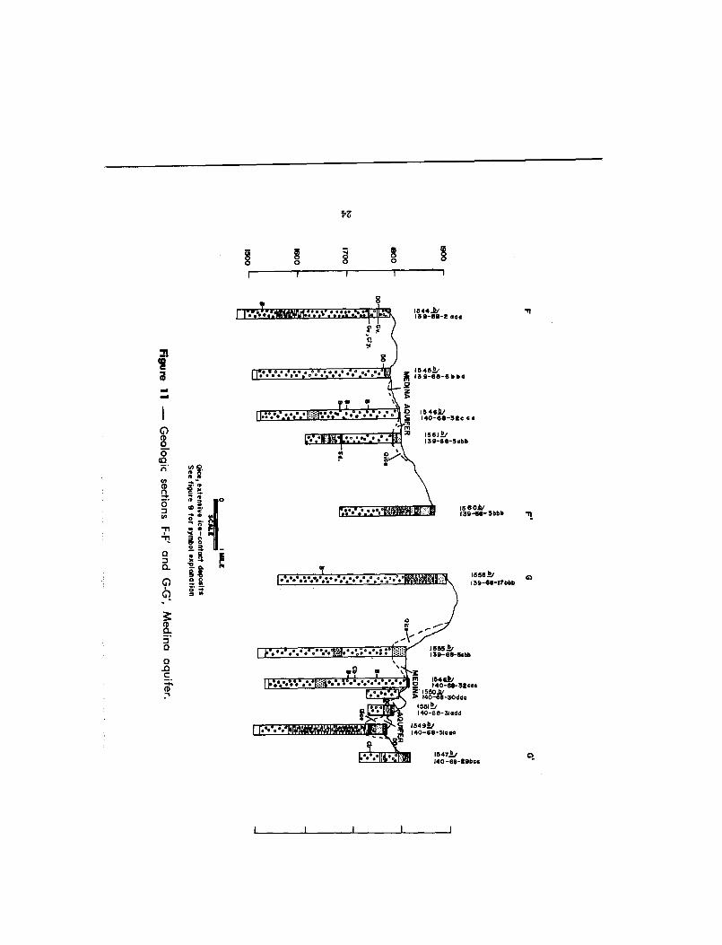
Medina aquifer . — The extensive ice contact deposits in the vi-cinity of Medina (population 545, 1960 census), mapped as the Medin aaquifer (fig. 3, fig 11), furnish the town with its municipal watersupply. A 24-hour test of the aquifer indicates that it has a transmis-sibility of 74,000 gallons per day per foot . The performance of theMedina municipal well indicates that the aquifer can supply mod-erately large quantities of ground water. (See table 4. )
Goldwin aquifer . — An ice-walled gravel train (Winters, 1963 ,
p. 44-45) extends southwest from a point east of Woodworth an dmerges with the Marstonmoor Plain aquifer (fig. 3). This deposit hasbeen named the Goldwin aquifer . A test hole in the aquifer pene-trated 24 feet of surficial gravel overlying thick clay (test hole 1814 ,142-68-12cdd) ; the gravel constitutes a potentially good aquifer (fig .
14) .
Undifferentiated Outwash Deposits
Undifferentiated outwash deposits consist of isolated masses o fglaciofluvial sediments that are not characterized by a recognizable
landform (table 2) . The deposits are scattered throughout the DriftPrairie and Coteau du Missouri of Stutsman County (Winters, 1963 ,pl. 1), are generally thin and discontinuous, and are usually under -lain by till . The areal extent of the sediments ranges from less thana quarter to about 2 square miles . Undifferentiated outwash de -posits composed of interbedded layers of clay, silt, sand, and grave lin varying proportions are known to be as much as 32 feet in thick-ness (test hole 302, 137-69-26bcbl, Paulson, 1952, fig . 8) .
The undifferentiated outwash deposits are generally of low to
23
Z
mCa
0
00
• w Cn•
ww
n g
qn
ao
• 40co
o
7'
.c'
1 n m
o e0
P• v
Y/
og'
i"dk'k-k6f1556 3139-66-17bbb
M:I .ZC =WEIR
CD0
0
C
15551/139-66-5cbb
\
nowilssii*saumseasevica
A n
a -
C
m 16461/0
140-68-3tcccZ 1550./
140-68-3Odda1551)140-68-31 ad d
1549)140-6 $-31a a o
15 4111140-65-tOboe
0
C
CD1
0
moderate permeability. Data on 10 wells developed in undifferentiatedoutwash deposits in the county were collected during this investiga-tion . All are small-yielding wells used for domestic or stock-wateringpurposes. Although the undifferentiated outwash is not a source oflarge supplies, where it is thick and extensive enough to provideappreciable ground-water storage, it may provide a potential sourc efor small supplies. Undifferentiated outwash deposits may also act a savenues of recharge to buried aquifers with which they are hydrau-lically connected. For example, it is likely that the undifferentiate doutwash mapped in the vicinity of Streeter serves as a source of re-charge to the buried aquifer that furnished the town with its wate rsupply . '
GLACIOLACUSTRINE SEDIMENTS
Glaciolacustrine sediments are deposited in proglacial lakes . De-posits of glaciolacustrine material in the form of lacustrine plainsand perched lacustrine plains are numerous in Stutsman County(Winters, 1963, pl . 1) . Winters, (1963, p . 23-24) has discussed the formand origin of these deposits .
Laminated silt and clay in the form of low-lying flat plains hav ebeen identified as lacustrine-plain deposits . They are of small arealextent and continuity, generally thin, and are not aquifers .
Perched lacustrine-plain deposits consisting mainly of laminate dclay, silt, and fine sand, are numerous throughout western StutsmanCounty. Some are at a higher altitude than the surrounding terrain .They are discontinuous and limited in areal extent . The thickness o fthe perched lacustrine-plain deposits ranges from less than a few fee tto at least 46 feet (test hole 1559, 139-68-31ddd, fig. 3, and Winters ,1963, pl . 4) .
The perched lacustrine-plain deposits are generally not aquifers .They are, however, sufficiently permeable to permit a small amoun tof ground-water movement. Auger holes in these deposits ordinarilypenetrate a distinct water table and the presence of springs and seep salong the margins of the deposits indicates lateral ground-wate rmovement . It is possible that some of the more permanent pondsbordering perched lacustrine-plain deposits in T. 142 N., R. 67 W .(Winters, 1963, pl . 1) are replenished by lateral movement of groun dwater. Shallow wells in a few such deposits yield small quantities
' Paulson (1952, p . 27) has called the deposits that are called undifferentiated out .wash deposits in this report, "ice-crevasse fillings."
25
of water. The perched lacustrine-plain deposit northwest of Medin ain T. 140 N., R. 69 W. is composed primarily of fine sand. Three low -yielding farm wells are located in the deposits underlying this plain .
BURIED GLACIOAQUEOUS SEDIMENT S
Buried glacioaqueous sediments are, in general, similar genetic -ally and lithologically to the surficial glaciofluvial and glaciolacus-trine sediments .
Buried glacioaqueous sediments are classified in table 2 as : (1)undifferentiated sand and gravel deposits, (2) undifferentiated sil tand clay deposits, and (3) buried-valley deposits . The types may grad einto one another both laterally and vertically . The first two geohydro-logic types are distinguished entirely on the basis of their lithology.The third type is found only in association with bedrock lows whic hprobably represent buried preglacial or proglacial valleys .
Undifferentiated Sand and Gravel Deposit s
Undifferentiated sand and gravel deposits are distributed ran-domly throughout the drift of Stutsman County. They have beenpenetrated by test holes at depths ranging from a few feet (test hole1805, 142-63-19ddd) to more than 400 feet (test hole 1821, 144-69-24ddd )and range in thickness from less than 2 feet (test hole 1747, 138-64-29cdd) to more than 100 feet (test hole 1923, 142-69-2ddc, Winters ,1963, pl . 4) .
Most of the undifferentiated sand and gravel is unconsolidated bu tzones of partly cemented material ranging from 1 foot to over 40feet in thickness have been penetrated in some test holes . The ce-menting material is generally calcium carbonate but consists of ironcompounds in some places; it appears in the drill cuttings as angularshards.
The overall range in extent and configuration of the undifferen-tiated sand and gravel deposits is obscure . Based on evidence fro mdrilling and from well data, the deposits are usually discontinuou sand rarely can they be correlated for more than a mile . Detailed sub-surface exploration is needed to define the individual deposits mor eprecisely .
Most undifferentiated sand and gravel beds probably were de-posited in glaciofluvial environments . Valley outwash deposits, whic hare protected by their containing walls and their low altitudes, are
26
NN
°rk
• •
• Bea .
EXPLANATION
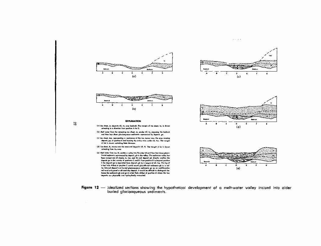
(a) Ion sheet, ia, deposits till, ta, over bedrock . The margin of ice sheet, ia, is show nreheating in direction from position A to G.
(b) Melt water from the reheating it. sheet, la, erodes till, to, exposing the bedroc kand then lays down glonioaqueos sediments represented by deposit, ga.
(c) Ice shot, Ma, representing a rodvance of the ice, moves over the area erodin gdeposit, go, at position E and burying the entire area under till, too . The marginof ioa is shown retreating framake
. -
(d) Ice shot, b, moves over the area and deposits till, tb . The margin of ib is shownretreating from the area.
(e) Melt water from ice, ib, modes o volley into the older till and then lays down glacio-fluvial sediments represented by deposit, gb in the valley. The meltwater valley ha sbeen incised into till shots, to, too, and tb and deposit gb directly overlies th edeposit go in the vicinity of positions C and P. From position D to beyond positionE the deposit go is separated from deposit, gb by a tongue of till, too . The log ofa test hob drilled at position E would newrd gladoflurial sediments gb as a val-ley ...Awash deposit and buried glacioaqueous sediments go as an ondifferotia-ted sand and gravel or silt and cloy deposit . It would be difficult to distinguish be-tween the sediments 66 and ga in a test hole drilled at position D where the tw odeposits are physically and hydraulically connected .
ti?_.mss _~_ _ _
•• /~~ 'etn'
D
E
F
6
(d )A
A
B
t
D
E
F
6
(a )
Figure 12 — Idealized sections showing the hypothetical development of a melt-water valley incised into olde rburied glacioaqueous sediments .
\\\ \ \ \ \\\ \
(d )
Block (a) shows a glaciated area from which the ice margin is retreating. Valley outwash deposits underlying the valley train and unconfined outwash deposits under -
lying outwash plain have been laid down by melt water from the retreating ice. Block (b) shows the area free of ice . Till (2) has been deposited by the glacial ice an d
underlies an end moraine. Block (c) shows the same area covered by ice of a glacial readvance . The ice is depositing till over the entire area burying the valley outwas h
and unconfined outwash deposits . Block (d) shows the area after the ice margin has retreated. A thick layer of till has completely buried the landscape represente d
in block (b), preserving the underlying deposits intact .
Figure 13 — Diagrams showing the hypothetical development of deposits of buried glacioaqueous sediment .
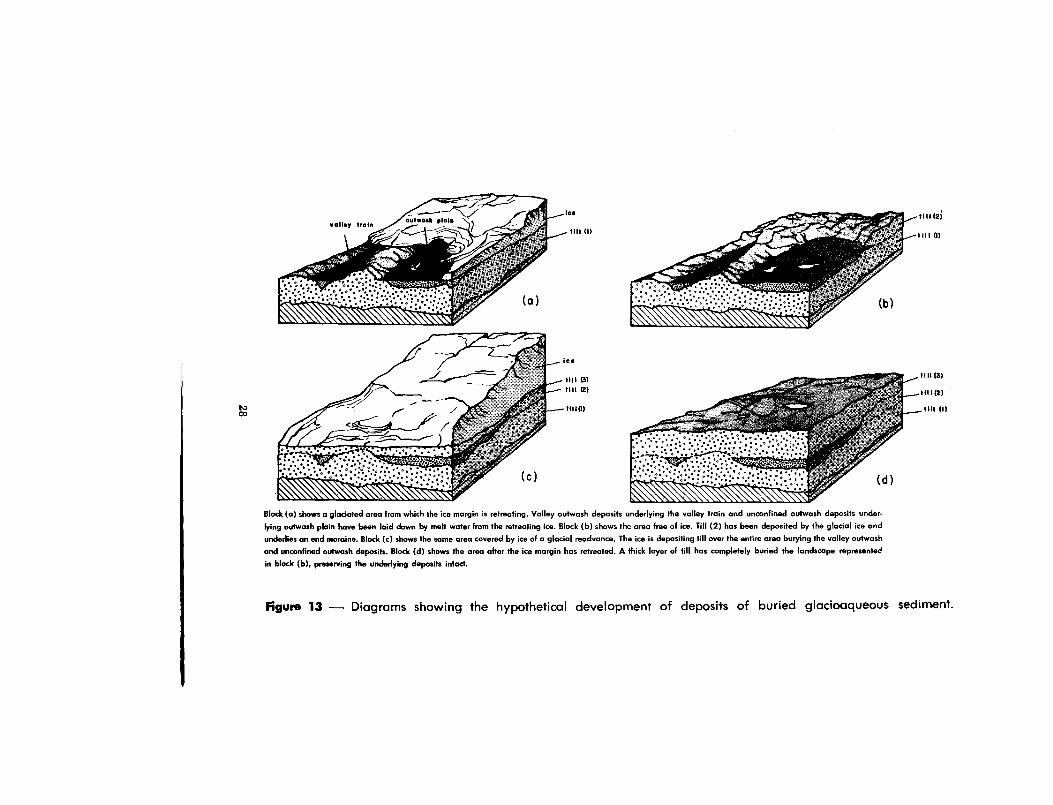
more likely to be buried intact than other glaciofluvial deposits .Many of the undifferentiated sand and gravel deposits are probabl yremnants of proglacial outwash deposited in valleys that were cu tinto older till and subsequently buried by later ice advances (fig . 12and 13) .
Eric Lake aquifer . — The Eric Lake aquifer is penetrated by 3 tes tholes. and consists of thick deposits of sand and gravel overlying til l(fig . 14) . Although the deposits are classified as undifferentiated sandand gravel, it is possible that they are associated with a major buriedproglacial valley. The areal limits of the aquifer are poorly definedand only 3 wells are known to penetrate it (fig . 3) . The small amoun tof development in the aquifer is probably because the northwesternpart of Stutsman County is rather sparsely populated .
Upper Buffalo Creek aquifers. — The Upper Buffalo Creek aqui-fers occupy an area of about 5 square miles in T . 137 N., R. 66 W. ,and T. 138 N., R. 66 W. (fig. 3) . There are 3 flowing wells in the are athat range in depth from 120 to 310 feet . Two other deep wells in thearea are reported to have flowed in the past . All of the wells are usedto supply farms and the average rate of flow does not exceed abou t5 gpm. Test hole 1761 (138-66-35bbb, fig . 14) penetrated three distinc tdeposits of undifferentiated sand and gravel .
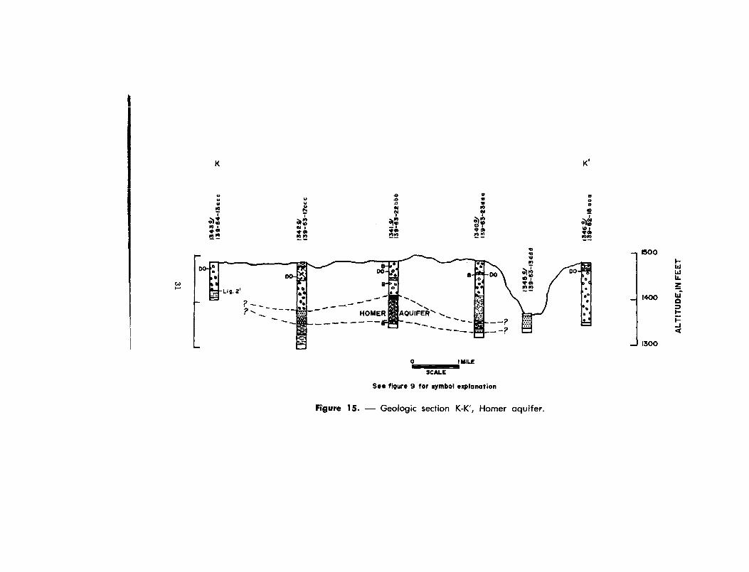
Homer aquifer . — In the central part of T. 139 N., R. 63 W., threetest holes penetrated relatively thick deposits of undifferentiated san d
and gravel (fig . 3 and 15) . These deposits contain water-bearing ma-terial called the Homer aquifer, which probably has an east-west di-mension of at least 4 miles . The thickness of the undifferentiated sandand gravel ranges from 20 feet in test hole 1340 to 47 feet in test
hole, 1341 . The aquifer consists of coarse sand and fine to mediumgravel, which include abundant quantities of detrital shale and some
clay . The deposits may be hydrologically and geologically connectedwith the valley outwash deposits in the James River valley .
The farm wells in the area have small yields, but wells withhigher yields could be developed due to the thickness and extent o fthe deposits. Water levels in wells penetrating the aquifer are ap-proximately 100 feet below land surface ..
Klose aquifer . — The Klose aquifer is located in southeasternStutsman County (fig . 3) . Its presence is indicated by data from 10wells all of which have high water levels and produce from a rela-tively shallow aquifer ; one of the wells flows . No test holes were
29

H '
IB0 0
1100
1600
50 0
400
1600
100
000
1500
400
.cu[
0lJ0,WkIH.M1ntlat .d solid and aray.I d.pa.iM; OI ., .arm .i0. I.-oon+acr 4 .50011 . ; and0uc,unditt.r.nriar.d ,ilr and cloy 0.00.1, . of 0umvnwy aa.
S. Bwr . B for .ymSol . .plant on
Figure 14 — Geologic sections H-H' and J-J', Goldwin aquifer, Eric Lak e
aquifer, and Upper Buffalo Creek aquifers.
30
K
K '
u 0 0 au u aa u a eaN 11''! NN
0N 0i
10NION
aNN NiMN
Mldb
NN
N
.AN'2
lbIf +
NN
- 1500
- 1300
1400
MIL E
SCALE
See figure 9 for symbol explanatio n
Figure 15 . — Geologic section K-K', Homer aquifer .
drilled in the vicinity of the aquifer . The aquifer may receive re -charge from an esker and a small glacial melt-water channel (Winters,1963, pl . 1) .
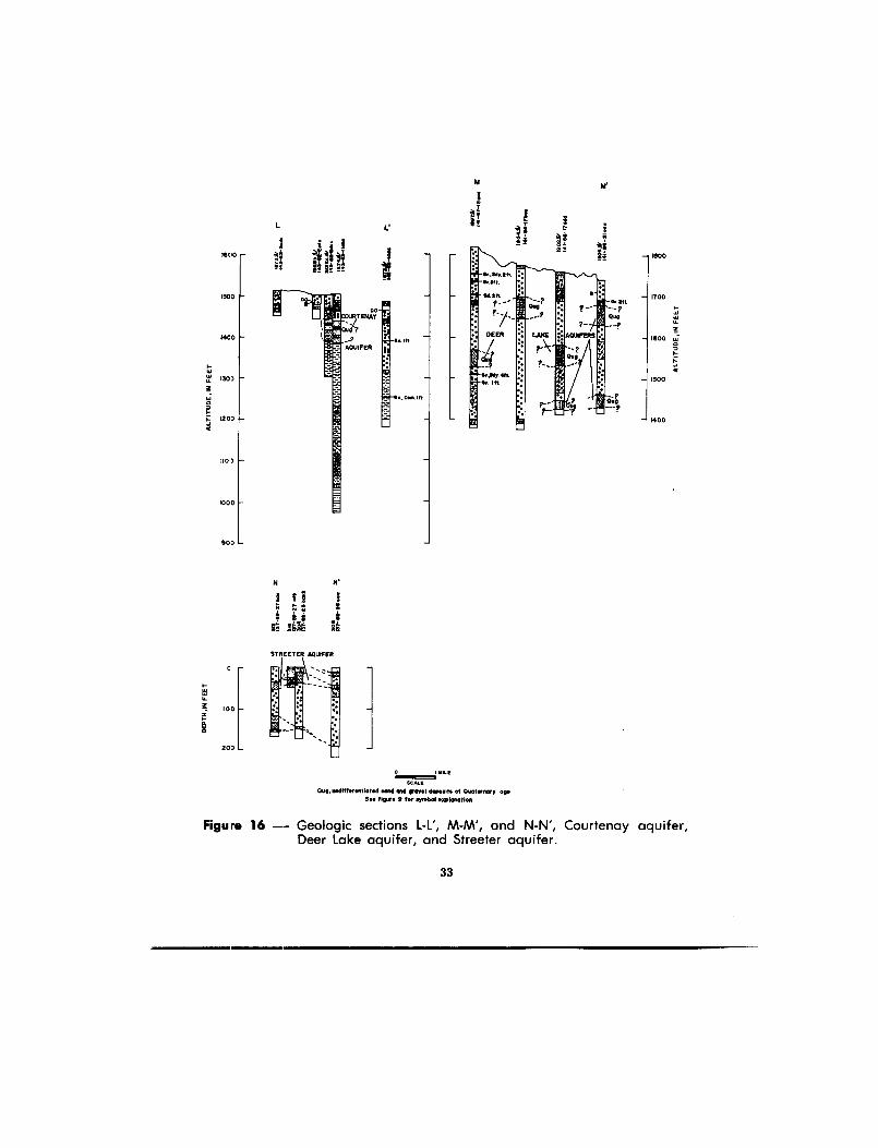
Courtenay aquifer. — The Courtenay aquifer is located in north -eastern Stutsman County (fig . 3 and 16) . The aquifer is 68 feet thickin test hole 1928c and 53 feet thick in test hole 1874. Several holesaugered into the aquifer were equipped with casings and used toobserve water-level fluctuations .
At least one farm obtains its domestic and stock-water suppl y
from wells penetrating this aquifer . Although it is not areally ex-tensive, the aquifer is thick and is present at a shallow depth; prob-ably, therefore, it can be recharged through the overlying till mor ereadily than aquifers that are deeply buried . Several aquifers of thistype exist within the upper part of the drift in Stutsman County ,although few are as thick or as potentially prodctive as the Courtenayaquifer .
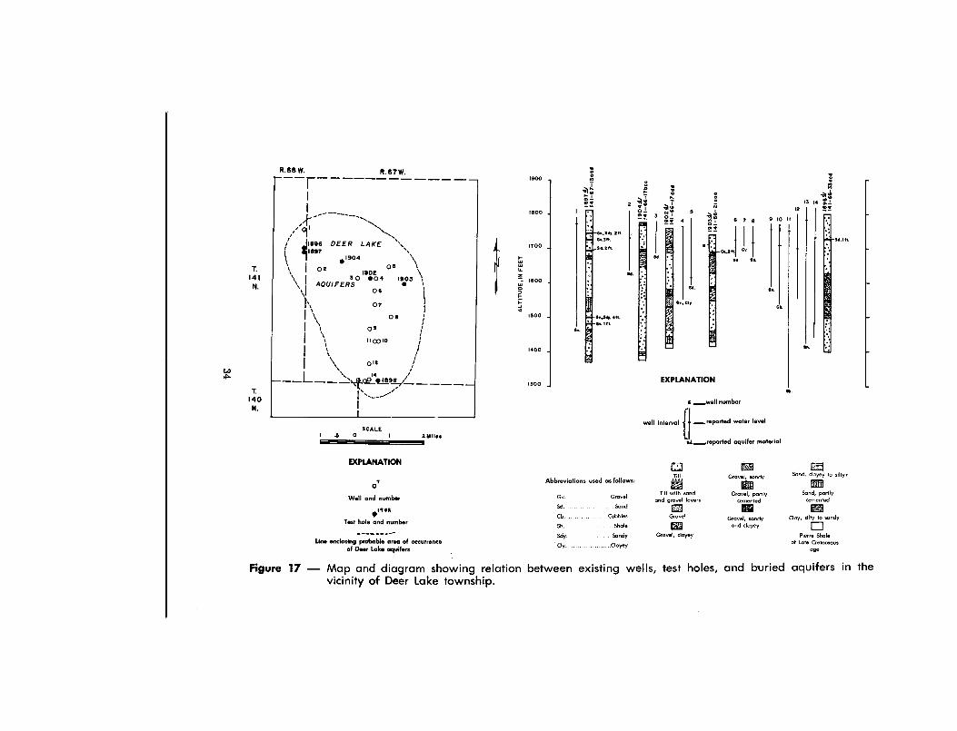
Deer Lake aquifers . — Deposits of undifferentiated sand andgravel, penetrated by 4 test holes in the Deer Lake Township area ,comprise a group of apparently unconnected aquifers (figs . 16 and 17).
The various undifferentiated sand and gravel deposits in the Dee rLake Township area are of considerable thickness; nevertheless, the ymay have low permeability because of clay within the sand an d
gravel, interbedded layers of clay, and (or) the presence of partl ycemented materials.
Streeter aquifer. — Streeter (pop . 485, 1960) obtains its water
supply from a shallow undifferentiated sand and gravel deposit over -
lain by till (fig . 16). The aquifer is probably connected with the un-differentiated outwash deposits west of the town and receives re -charge through these deposits (Paulson, 1952, p . 38-42) . The config-uration of the Streeter aquifer and recharge area is shown on fig. 3 .The relation between the aquifer and the recharge area is illustrate din fig. 4a .
Undifferentiated silt and clay deposits
The undifferentiated silt and clay deposits are composed predom-inantly of silt and clay-sized particles . They range from smooth tosandy and from weakly cohesive to very tight .
Undifferentiated silt and clay deposits that range in thicknes sfrom 1 foot to 161 feet were penetrated during test drilling. Theirpattern of distribution throughout the drift is equally as complex as
32
St.csm.IR.
1000
L L'
1800
150 0
100 0
1100
— 1000
ITOO
1600
1500
— 140 0
80D
STREETER AQUIFE R
0
200 —
0
YILEtlmmmmnis
SOALLQSBrrpldiNSrSstiot.E sad aN growl deposits of Ouotsrnory asp
Sw 'Moro 9 for symbol sxplanotlon
Figure 16 -- Geologic sections L-L', M-M', and N-N', Courtenay aquifer ,Deer Lake aquifer, and Streeter aquifer .
33
T.14 1
N.
T.14 0
N .
1300
,500
1400
800
900
1700
a.
SCALE.5
0
1
26111 . .
Ce.
EXPLANATIO N
JrI
6
wall numbe r
well interval
LI
. .reported wafer level
al/..---.reporfed aquifer materia l
R .68 W .
R.67 W.
\\I
`
AQUIFERS004 1.0 3
1902
O 6
~ys
07
111
\ o eI
0 9
110010
I
tI1
~01 2
14
/r
~
\,01 1
ri 1ile90 DEER LAKE
1 18x71904
~
0 2
\
05
lem2 0
af
a e21 4
_av 3 o f
46,60,211.
s. .sn.S1. tn.
d W
n a
6 7 8
9 10 I I
I
ma
_
ell
a s
a . .
4 ..36.
12
de13 14 p`
2
es .
EXPLANATION
Til l
Grave l
Gravel, clayey
Grovel, sand y
Till with sandand grovel layers
Grovel, partl ycemented
Gravel, sondyand clayey
is07
Well and number
Test hole and number
Lire enclosing probable area of occurrenceof Deer Lake aquifers
Abbreviations used as follows :
Gv Grave lSd .
SandCb CobblesSh ShaleSdy.
SandyCly .. . Clayey
Sand, clayey to silty .
Sand, portl ycemented
Cloy, silty to sand y
I]Pierre Shale
of Lote Cretaceousage
Figure 17 — Map and diagram showing relatio nvicinity of Deer Lake township .
between existing wells, test holes, and buried aquifers in the
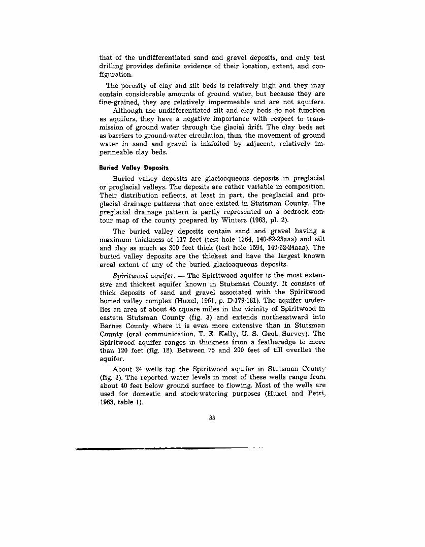
that of the undifferentiated sand and gravel deposits, and only tes tdrilling provides definite evidence of their location, extent, and con -figuration.
The porosity of clay and silt beds is relatively high and they ma ycontain considerable amounts of ground water, but because they arefine-grained, they are relatively impermeable and are not aquifers .
Although the undifferentiated silt and clay beds do not functio nas aquifers, they have a negative importance with respect to trans -mission of ground water through the glacial drift . The clay beds actas barriers to ground-water circulation, thus, the movement of groundwater in sand and gravel is inhibited by adjacent, relatively im-permeable clay beds.
Buried Valley Deposits
Buried valley deposits are glacioaqueous deposits in preglacia l
or proglacial valleys. The deposits are rather variable in composition .Their distribution reflects, at least in part, the preglacial and pro -glacial drainage patterns that once existed in Stutsman County . Thepreglacial drainage pattern is partly represented on a bedrock con -tour map of the county prepared by Winters (1963, pl . 2) .
The buried valley deposits contain sand and gravel having amaximum thickness of 117 feet (test hole 1364, 140-62-23aaa) and siltand clay as much as 300 feet thick (test hole 1594, 140-62-24aaa) . Theburied valley deposits are the thickest and have the largest know nareal extent of any of the buried glacioaqueous deposits .
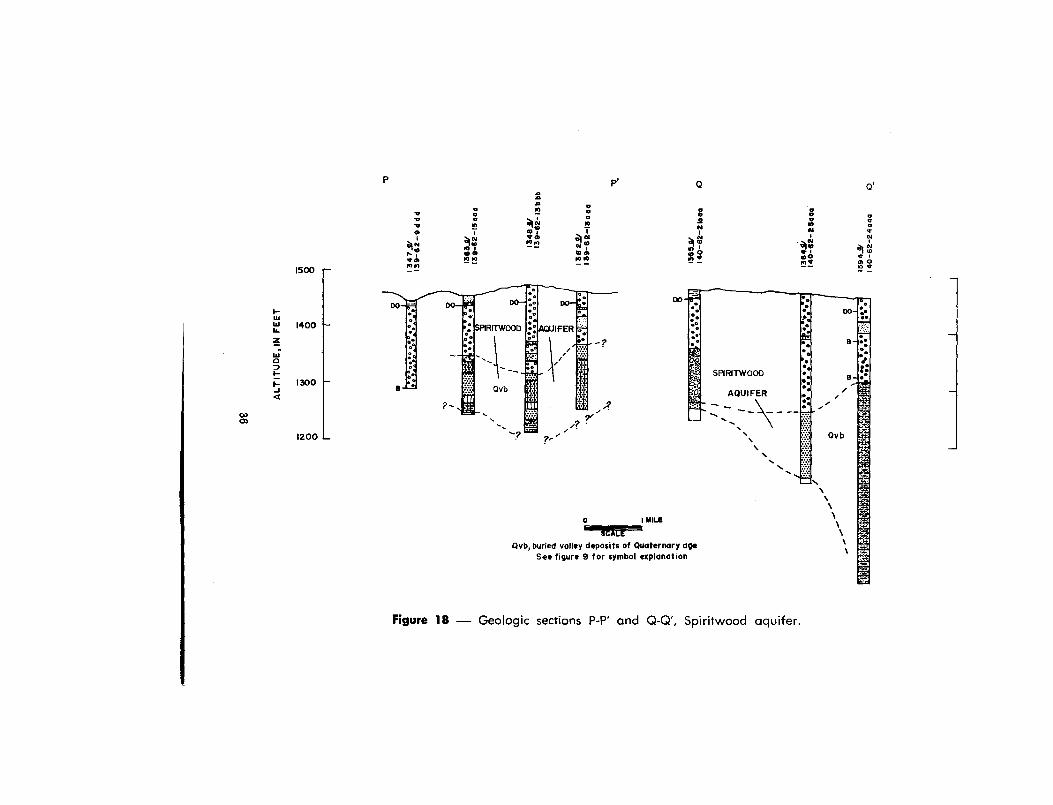
Spiritwood aquifer . — The Spiritwood aquifer is the most exten-sive and thickest aquifer known in Stutsman County . It consists of
thick deposits of sand and gravel associated with the Spiritwoodburied valley complex (Huxel, 1961, p . D-179-181). The aquifer under -
lies an area of about 45 square miles in the vicinity of Spiritwood ineastern Stutsman County (fig . 3) and extends northeastward intoBarnes County where it is even more extensive than in Stutsma nCounty (oral communication, T . E. Kelly, U. S. Geol . Survey). TheSpiritwood aquifer ranges in thickness from a featheredge to morethan 120 feet (fig. 18) . Between 75 and 200 feet of till overlies th eaquifer .
About 24 wells tap the Spiritwood aquifer in Stutsman Count y
(fig. 3) . The reported water levels in most of these wells range fro m
about 40 feet below ground surface to flowing . Most of the wells ar eused for domestic and stock-watering purposes (Huxel and Petri ,1963, table 1) .
35
1500
P
P.
Q
Q '
0 o aeV m aN
0A s
N
ee
ac
°o. 1 v
701 INto
I NN le ml ~ N m
mq m I aIm 41 m
amm m
M MM m yM _ 0 ai1.710
Figure 18 — Geologic sections P-P' and Q-Q', Spiritwood aquifer .
I200
1400
1300
0
IIMILE
SCALE
Qvb, buried volley deposits of Quaternary ag e
See figure 9 f or symbol explanation

Discharge from the Spiritwood aquifer in Stutsman County is b yunderflow to adjacent areas and withdrawal of water by wells. Thetotal discharge through wells is small. Recharge to the aquifer is byseepage through the overlying drift and by upward leakage fromadjacent bedrock. Natural discharge by upward leakage through rel-atively impermeable deposits may occur at some places . The relativel ylow total dissolved-solids content of water from the Spiritwood aqui-fer suggests that there is appreciable ground-water movement throughthe deposits .
Windsor aquifers . — Test holes in the vicinity of Windsor pene-trated the deposits of a buried valley in which there is one or mor eaquifers, which in this report are called the Windsor aquifers (fig . 3) .The Windsor aquifers are under artesian conditions, and six wells i nthe aquifer flow . There are 10 wells penetrating the aquifer in th earea and these wells range in depth from 113 to 400 feet . In test hole1582, (fig. 19) 41 feet of sand and gravel are penetrated, and in tes thole 1584, 68 feet of partially cemented gravel were found overlyin gthe Pierre Shale. Because the Windsor artesian aquifers lie in a burie dvalley system, it is possible that they may extend beyond the areashown in figure 3 .
Midway aquifer. — Thick buried valley deposits contained in a
bedrock low in Midway Township (T . 140 N., R. 64 W.) were pene-trated by test holes (fig. 3) . The sand and gravel of these deposits isextensively interbedded with silt and clay. The sand and gravel con-tains clay in some places and is partially cemented in others (fig . 19) .Consequently, although the deposits are thick, the permeability is
low at some sites .
Mount Moriah aquifer . — The Mount Moriah aquifer (fig. 3) con-sists of sand and gravel . Test hole 1922 (fig . 19) penetrated 245 feet o fthe deposits, which underlie 160 feet of till. The sand and gravel isextensively interbedded with silt and clay and in many places con-tains clay or is partly cemented . The deposits may be associated with
the ancestral Cannonball Valley (Winters, 1963, p . 33-36 and pl . 2). Nowells are known to tap the aquifer, but this may simply be due to thefact that it has not been explored rather than to any limitation in
the permeability or areal extent of the aquifer.
Sydney aquifer . — Near Sydney, a buried valley is cut into th e
bedrock. The aquifer consists of sand and gravel . The thicknessof the aquifer ranges from 13 feet in test hole 1756 to 47 feet in tes t
hole 1.752 (fig. 19) . No wells are known to tap this aquifer .
37
TILL
The most extensive landforms of Stutsman County are end mor-aine, ground moraine, and hummocky stagnation moraine (Winters ,1963, pl. 1) and all are composed largely of till . Till is also the mostabundant drift material in the subsurface and it influences much o fthe ground-water movement. Test holes have penetrated till tha tranged in thickness from less than 10 to 400 feet .
The typical till of Stutsman County consists of an unstratifiedand unsorted mass of silty to sandy clay that binds together largerfragments of igneous, metamorphic and sedimentary rock . The natureof the till in the subsurface has been determined from test drillin g(Huxel and Petri, 1963, p. 6-9) . Lithology of the surficial till was de-scribed in detail by Winters (1963, p. 24-34) .
Geohydrologic variations in till lithology are shown by the di -vision of the till into units in each test-hole log (Huxel and Petri ,
1963, table 2). These till units do not necessarily have stratigraphicsignificance; rather the observed variation in gross till lithology i sdescribed .
The permeability of till is generally very low and it is not con-sidered an aquifer. In most cases it restricts the movement of groun dwater into or out of more permeable deposits that it completely orpartially encloses . The till is not, however, an absolute barrier toground-water movement. Wells have been dug as much as 80 fee tinto the till and have been reported dry at the time of their comple-tion. Over a period of months these "dry" wells gradually accumulat eground water until their water levels finally stabilize .
The differing till lithologies and their patterns of distributionin the subsurface can be important in ground-water studies . Differ-entiation of tills of differing permeabilities permits evaluation of re -charge possibilities to buried aquifers adjacent to the tills . For ex -ample, a buried aquifer that is contiguous with a till that is inter -bedded with sand and gravel or a sandy till has a greater rechargepotential than an aquifer that is continguous with a silty or clayey till .
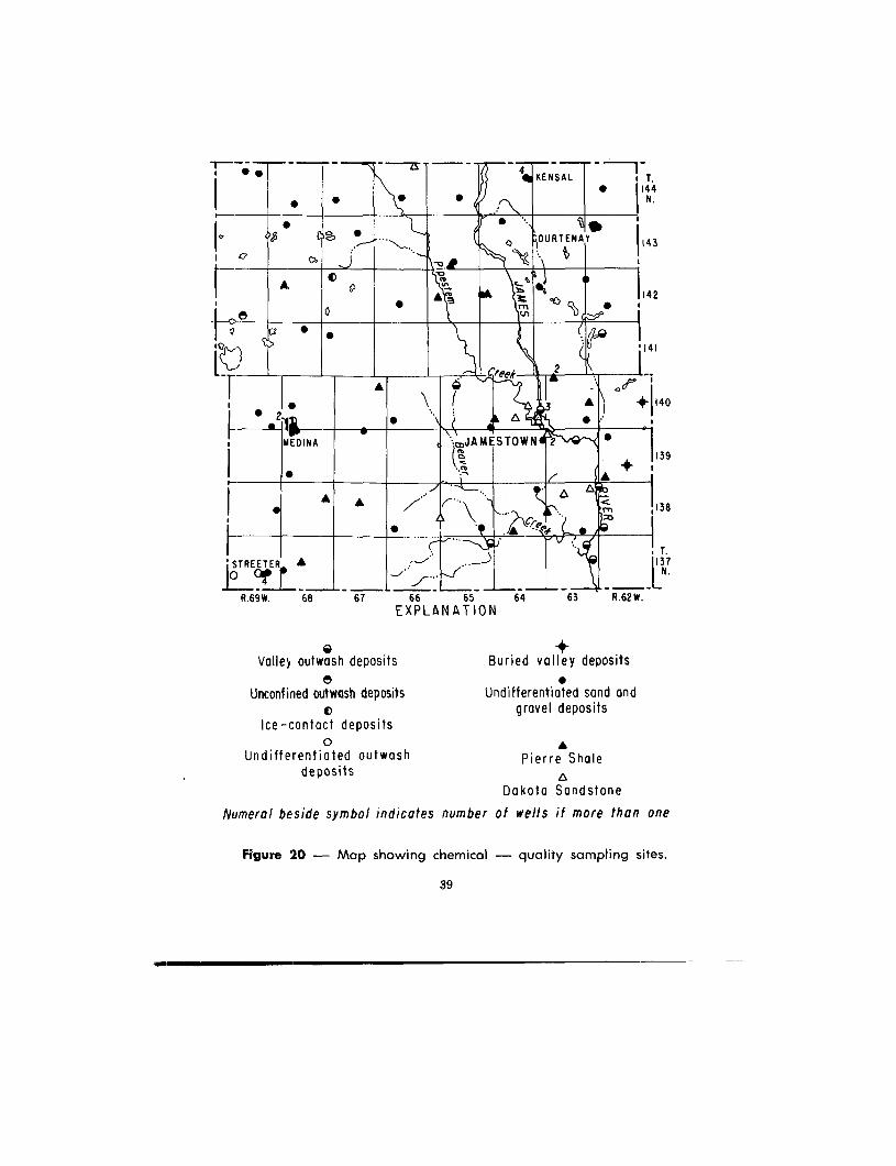
CHEMICAL QUALITY OF THE WATE RThe chemical quality of ground water generally is attributable t o
inorganic solids dissolved from the earth materials with ' which thewater has had contact . These dissolved solids may cause hardness o fthe water, stain laundry, discolor food products, form scale in pipes ,and produce other undesired effects . Significant amounts of thes edissolved solids may limit the economic use of the water .
38
I—
• - - --~ - - - - -1-aKENSAL ,
T .
• • • •• I 14
N
I°
°~11
~°c~ •' J
'w• I
Q OURTENAY 1 4
O flo
k
,'p
• A l a
• • 11a
L •• . - ♦
IMEDINA •m JAMESTOWN ~~~~ •
I'
a
CrP
6
' STREETER
R.69 W .
68
67
66
65
64
63
R .62 W .EXPLANATION
3
2
14 0
13 9
13 8
T .13 7
N .
Valley outwash deposit se
Unconfined outwash deposit s0
Ice-contact deposits0
Undifferentiated outwas hdeposits
Buried valley deposit s•
Undifferentiated sand an dgravel deposit s
aPierre Shal e
Dakota Sandston e
Numeral beside symbol indicates number of wells if more than on e
Figure 20 — Map showing chemical — quality sampling sites .
39
of,
Fi ll
1111
111 111 MI.a .
~~1 OWN F~
m m• : FF~
~ G1N N Kn
O'
~i'i YO FJ~Lo.
~1 Q~W ~O 1+
m m• . rrr
n n0 Ov
Ul !O+~ r
:Pi
Y H F—'
N 0>
r
r r
r
r r Cob os o o\
(n FN FF O tN~ V OJv F O O v O N O Wv 000r 007
n
r-~V O 0 nv
$~~wG
00-.,NA GYSnW 0
nH 4~~
,~ GN
rmNU,
0VFi&W Hw =2
v
Lo ro
GGG~ =
F Fw C'.--4 WNOv
COWyy toF10 ,O
Y W N
1~-
O O O N
vwN
wn€~O'
:88t
SO F'r"
W ANN
{Y{Y
aNWW N
000n o,o
WW,F
wN .N
N—FFOFOO) F
rr FHO FO l~
Ww
W
1-1 -4 G
ss e.
FFNF-- Co,.•O ~n FWv
i£S
ppO ~
W ~ O J
r l+~
IV F,0W
to tOut
N
8 .9 8 Z
O '.j' Fb
m 00(0 co_.N
5
rg 'a
ip
r
r
w
NOGO
OWN 812 :2
o ..
W SW FW F
W% .osg
V+ Nza' :50 1,
Vr ..
n.rl
• r
w
• 8Z
P
a
. 6
8ap°...4 7
a
9
I
6
5
N N H W.0w O Cov W 0- 0 0,
t F ,O_
NN NG 0:1U1 W vO • O• ._.
N nO O W.
W W VN O srD -1W
W O V
G1W F
O
O
W N F~"~ W WI;S msws
pppv
N W1
N Y a\v
v 6
4- -71 ,Q"
-'
v
r 00~p~p00 wO O N
N N CO
0o-Io-
NwN O\
oo~o°
yy~~w3So.Yg-
m m
e l
W m
a-
a
CD1
The chemical analysis of water from more than a hundred well sand springs in Stutsman County were studied to determine the suit -ability of the water for use .
The chemical quality of the ground water is influenced by thechemical and physical characteristics of the sediments through whichthe water moves. Therefore, water quality may range significantl yfrom one geologic unit to another . The areal distribution of the sam-pling sites is shown in figure 20 for each of the geohydrologic units .The sampling sites for water from the Pierre Shale and from un-differentiated sand and gravel deposits are fairly numerous and ar ewell distributed throughout the county and are chiefly from domesti cand stock wells. Samples were obtained from all the wells that wereknown to produce water from the Dakota Sandstone . The DakotaSandstone underlies the whole county at relatively great depths . Dis-tribution of sampling sites for water from valley outwash deposits ,outw ash plain deposits, ice-contact deposits, and buried valley deposit swas limited by the relatively small areal extent of these units.
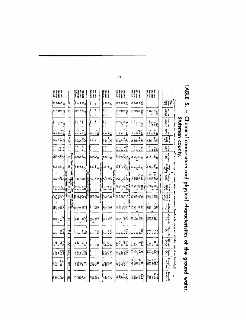
The chemical composition and physical characteristics of th eground water are summarized in table 5 from chemical analyses givenin tables 3 and 4 of Huxel and Petri (1963) .
Most of the samples were analyzed 1950-62, but some were an-alyzed as early as 1909. Methods of laboratory analysis and of re-porting analytical results differed somewhat from one agency to
another. To provide uniformity, some of the laboratory results origi-nally reported were converted to present standard reporting units o fthe U. S. Geological Survey .
Variations of ground water temperature with well depth wer e
evident. The water from wells less than 20 feet deep varied from
42 to 51°F; from wells 21 to 120 feet deep, 43 to 45°F; and from well s
120 to 340 feet deep, 45 to 49° F . Water from wells penetrating th e
Dakota Sandstone, at depths of about 1,300 to 2,000 feet is about 73°F .Temperature of the water from the Dakota Sandstone in Barne sCounty ranged from 68 to 72°F (Kelly, 1964, table 4) .
Water from both the Cretaceous bedrock and the Pleistocene drif tis nearly colorless when it is discharged from the well . Generally ,
iron and manganese precipitate soon after the water is exposed t o
the air and the water appears to be colored. These precipitates wil l
settle to the lbottom of a container if the water is allowed to stand .
Most of the water in Stutsman County is very hard . The hardes t
water is from undifferentiated sand and gravel deposits, and th esoftest water is from Pierre Shale .
41
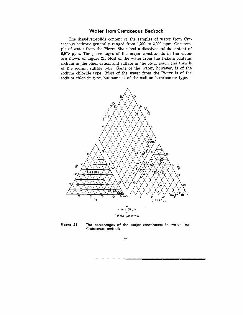
Water from Cretaceous Bedroc kThe dissolved-solids content of the samples of water from Cre-
taceous bedrock generally ranged from 1,000 to 3,000 ppm . One sam-ple of water from the Pierre Shale had a dissolved solids content o f6,970 ppm. The percentages of the major constituents in the waterare shown on figure 21 . Most of the water from the Dakota contain ssodium as the chief cation and sulfate as the chief anion and thus i sof the sodium sulfate type . Some of the water, however, is of th esodium chloride type. Most of the water from the Pierre is of thesodium chloride type, but some is of the sodium bicarbonate type .
Ca
CI+F+NO 3
Pierre Shal e0
Dakota Sandston e
Figure 21 — The percentages of the major constituents in water fro mCretaceous bedrock .
4 2
--AWWWA
AWWWAY----AY
ao -- CATION S
AWWWAWWWAWLWAAWATAVAVANAVA
AVAVA-VAWAVAMAMMY/Ai►VAV fii
9 ♦ 'S
so
E.
20
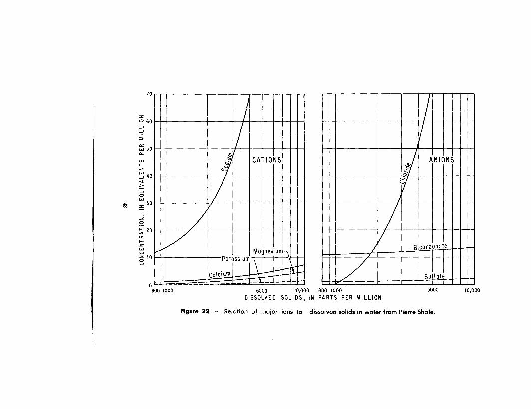
7 0
5 0d
z0
a 2 0
L.)1 00
V
0
III 1 I 1
~ CAT ION S
PotassiumMagnesium
C alcium
ANION S
c/0
Bicarbona te _
Sulfat e
5000
10,000
800 1000DISSOLVED SOLIDS, IN PARTS PER MILLIO N
800 1000 5000 10,00 0
Figure 22 — Relation of major ions to dissolved solids in water from Pierre Shale .
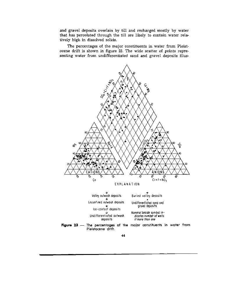
and gravel deposits overlain by till and recharged mostly by waterthat has percolated through the till are likely to contain water rela-tively high in dissolved solids .
The percentages of the major constituents in water from Pleist-ocene drift is shown in figure 23. The wide scatter of points repre-senting water from undifferentiated sand and gravel deposits illus -
c l'''
X % :A!ArA`Q!A.
AWAV-AYJA.A.A
A.O~~.AVA.ALCM l►TATAYAYA
AWA NIAWAAMIKI. 'i0IMB4A.A
AYAW CATIONSAYAWA
40
20
a
•' --
° YATATA.A.A10310MIO:13ML
Z )VAWff .-AIMPPAIRMLIK1611k
*TAW ANIONS AWAao
0o
00CI+F+NO 3
40
8 080
60 60Y
2 0
EXPLANATIO N
cValley outwash deposits
eUnconfined outwash deposit s
0Ice-contact deposit s
0Undifferentiated outwas h
deposit s
Figure 23 — The percentages of th ePleistocene drift .
44
+Buried volley deposit s
Undifferentiated sand andgravel deposit s
Numeral beside symbol in-dicates number of wellsifmore than on e
major constituents in water from
The chemical character of the water from the Pierre Shale varie swith dissolved-solids content (fig . 22). Sodium is the principal cationof all dissolved solids concentrations . Bicarbonate is the principalanion in the water having less than about 2,000 ppm . Bicarbonat econcentration is consistently higher in water from the Pierre tha nin water frorn any of the other geohydrologic units .
Examination of table 5 discloses several noteworthy facts relat-ing to some constituents in the water in Stutsman County . The firstis that the boron content of the water from the bedrock is highe rthan that of water from the glacial drift . Generally, the boron con-tent of the water from the bedrock is from 1 to 5 ppm, whereas thatof water from the drift is less than 0 .5 ppm. Therefore, differencesin boron content may help to distinguish the geohydrologic sourc eof water.
The average of 2 .4 ppm of fluoride from the Dakota Sandston e
(table 5) contrasts sharply with the averages of 0 .4 ppm or less for
the water from Pierre Shale and Pleistocene drift. Only one sampl e(from Pierre Shale) had a fluoride content that exceeded the mini -
mum fluoride content of water from the Dakota . The fluoride con -
tent is helpful in differentiating between water from the Dakota an d
water from other units .
Two additional facts are the relatively low silica content of wate rfrom the Dakota and the low nitrate content of water from both the
Dakota and the Pierre . The silica content of water from the Dakota
averages about half that of the water from the Pierre and glacial
drift . Most high concentrations of nitrate in ground water are asso-ciated with drainage of nitrogen-laden water from barnyards, fer-tilized fields., and outhouses ; the thickness of relatively impervious
till overlying bedrock prevent seepage of such water into the bedroc k
aquifers .
Water from Pleistocene Drift
Aquifers in the Pleistocene drift located at or near the lan dsurface generally have water with low dissolved solids consistin g
mostly of calcium and bicarbonate . Aquifers in which many shalefragments or much till is incorporated generally have water with dis-solved solids that differ according to the amount and composition o f
the shale fragments or till present . Water from such aquifers gen-erally has, in addition to calcium and bicarbonate, significant con-centrations of sodium, sulfate, and, in some places, chloride . Sand
45
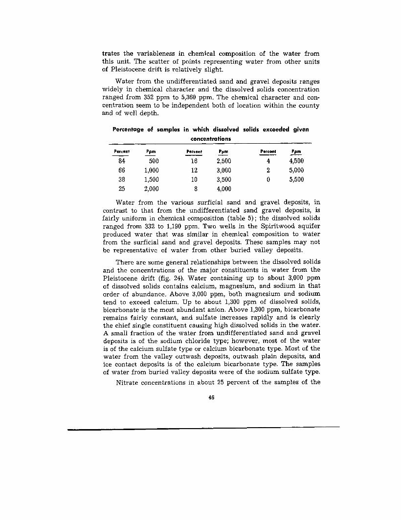
trates the variableness in chemical composition of the water fromthis unit . The scatter of points representing water from other unit sof Pleistocene drift is relatively slight .
Water from the undifferentiated sand and gravel deposits range swidely in chemical character and the dissolved solids concentratio nranged from 352 ppm to 5,360 ppm . The chemical character and con-centration seem to be independent both of location within the count yand of well depth .
Percentage of samples in which dissolved solids exceeded give n
concentration s
Percent Ppm Percent Ppm Percent Pp m
84 500 16 2,500 4 4,500
66 1,000 12 3,000 2 5,00 0
38 1,500 10 3,500 0 5,50 0
25 2,000 8 4,000
Water from the various surficial sand and gravel deposits, incontrast to that from the undifferentiated sand gravel deposits, i sfairly uniform in chemical composition (table 5) ; the dissolved solid sranged from 332 to 1,190 ppm . Two wells in the Spiritwood aquiferproduced water that was similar in chemical composition to wate rfrom the surficial sand and gravel deposits . These samples may notbe representative of water from other buried valley deposits .
There are some general relationships between the dissolved solid sand the concentrations of the major constituents in water from the
Pleistocene drift (fig . 24) . Water containing up to about 3,000 ppm
of dissolved solids contains calcium, magnesium, and sodium in tha torder of abundance . Above 3,000 ppm, both magnesium and sodiumtend to exceed calcium. Up to about 1,300 ppm of dissolved solids ,bicarbonate is the most abundant anion . Above 1,300 ppm, bicarbonateremains fairly constant, and sulfate increases rapidly and is clearl ythe chief single constituent causing high dissolved solids in the water .A small fraction of the water from undifferentiated sand and grave ldeposits is of the sodium chloride type ; however, most of the wate ris of the calcium sulfate type or calcium bicarbonate type . Most of thewater from the valley outwash deposits, outwash plain deposits, an dice contact deposits is of the calcium bicarbonate type . The samplesof water from buried valley deposits were of the sodium sulfate type .
Nitrate concentrations in about 25 percent of the samples of th e
4 6
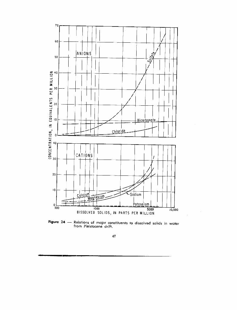
7
6
5
=30wa
)— /
//
ANIONS
/— //
/
-/
//
/
/Bicarbonat e
i
__~~ Chlori d e
C A
Co-
1000
5000DISSOLVED SOLIDS, IN PARTS PER MILLION
10,00 0
o —30 0
2 0
1 0
Figure 24 — Relations of major constituents to dissolved solids in wate rfrom Pleistocene drift .
47

water from shallow undifferentiated sand and gravel deposits ex-ceeded 45 ppm. The samples were from wells less than 40 feet deep.Many of the wells are in or near barnyards .
Suitability of the Water for UseThe ground water in Stutsman County is used principally for
municipal, domestic, and stock supplies . Most of the water used in-dustrially is from the few municipal supplies of which the largest is
the supply for Jamestown . At the present, ground water is used fo rirrigation in areas of valley outwash . Perhaps, irrigation may provefeasibile in some areas of buried valley deposits . The suitability o fground water for irrigation is also of interest to many residents wh oirrigate flowers, lawns, and small gardens .
MUNICIPAL, DOMESTIC, AND STOCK SUPPLY
Ideally, drinking water should be cool, clear, colorless, odorless ,
free of offensive taste, and free of pathogenic or noxious organisms .Also, it should be free of high concentrations of any chemical con-stituents that may be physiologically harmful, esthetically objection-
able, or economically damaging. Nature seldom provides such an"ideal" water ; few supplies can be found that could not be improve dby some form of water treatment.
For drinking water, most people prefer a temperture of 50°F o r
lower. According to the California Institute of Technology (1957) ,p. 392), temperatures of 60° F or higher are usually objectionable t omany people and temperatures of 65° F or higher are objectionable to
most people. The average temperature of about 45° F contributes sig-nificantly to the palatability of the water from Pierre Shale andPleistocene drift . The average temperature of 62° F, however, un-doubtedly detracts from the palatability of the water from the Dakot aSandstone. The low average temperature of most of the groundwater is undoubtedly an advantage to farmers in cooling and pre -serving dairy products destined for market .
Most of the ground water when pumped is clear, nearly color-less, and odorless. However, water from some of the old flowing wellstapping the Dakota Sandstone contains fine sand and rust particle swhich settle rapidly from the water . The water becomes cloudyupon exposure to the air because of the formation of iron, manga-nese, and possibly aluminum oxides . None of the water sampled hadobjectionable odor, but some had objectionable taste . Taste, however ,
48
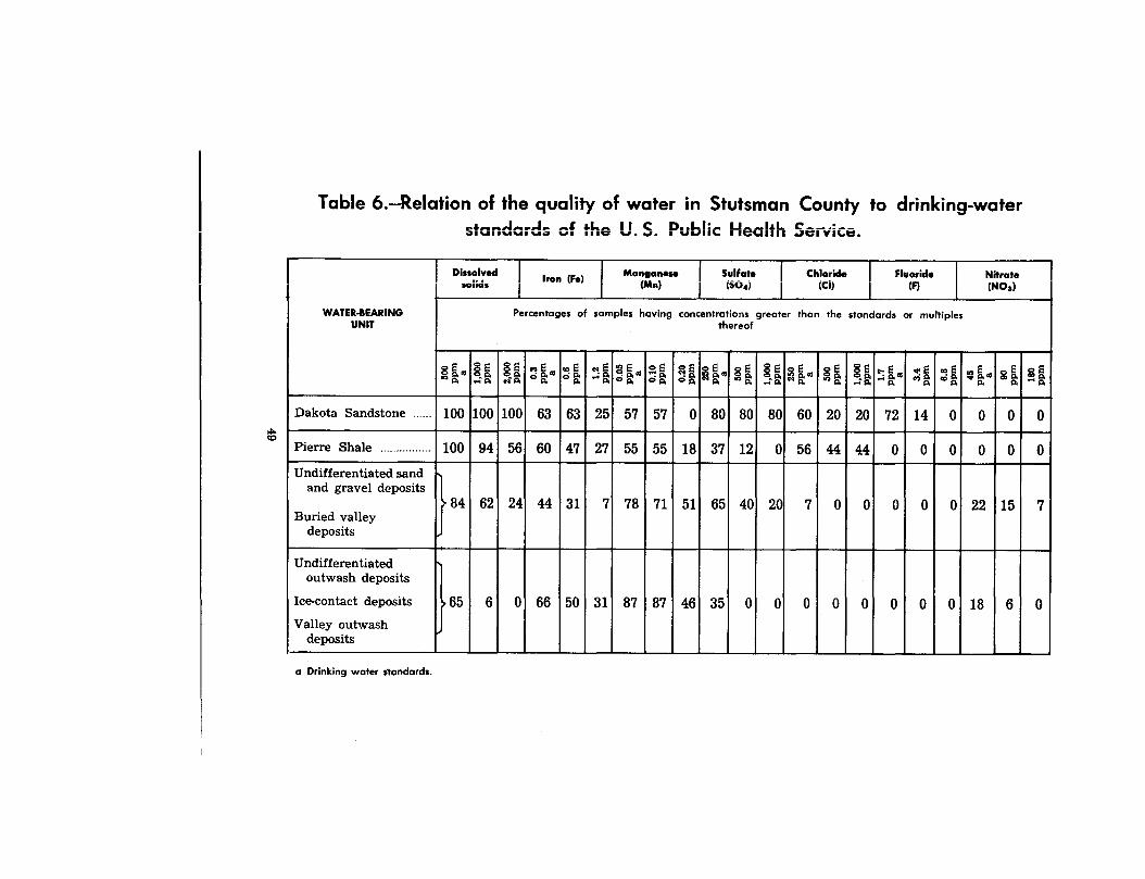
Table b .--Relation of the quality of water in Stutsman County to drinking-waterstandards -of the 11 C
Health Service.
l l
Dissolvedso lids
I
Iron (Fe) I
Manganese(Mn)
jSulfate(So.)
Chloride(CI)
FluorideI
(F)I
NitrateI
(NO3)1
WATER-BEARINGUNIT
Percentages of samples having concentrations greater than the standards or multiple sthereof
8a aa
§a ac,a oa ea oaa - oa ea
a oaNa Ra m
aSa
a$ a..a
ga ea
8 aa
Saa saea qaa ma wa sa $ aa °te a" a
Dakota Sandstone 100 100 100 63 63 25 57 57 0 80 80 80 60 20 20 72 14 0 0 0 0
Pierre Shale 100 94 56
yalc v. ., .
Public
a Drinking water standards.
60 47 27 55 55 18 37 12 0 56 44 44 0 0 0 0 0 0
Undifferentiated sandand gravel deposits
84 62 24 44 31 7
78 71 51 65 40 20 7 0 0 0 0 0 22 15 7Buried valley
deposits
Undifferentiate doutwash deposits
Ice-contact deposits 65 6 0 66 50 31 87 87 46 35 0 0 0 0 0 0 0 0 18 6 0Valley outwash
deposits
cannot be evaluated objectively, for what to one person may tast eobjectionable may to another . taste good. No attempt was made inthis investigation to determine the presence or absence in the waterof harmful micro-organisms .
The suitability of water for drinking commonly is evaluated inrelation to the standards of the U. S. Public Health Service (U . S.Department of Health, Education, and Welfare, 1962), which are given ,in part, in table 6 . The dissolved-solids content of most of the waterfrom the Dakota Sandstone, Pierre Shale, and undifferentiated san dand gravel deposits exceeds the recommended limit by several fold .The dissolved-solids content of most of the water from the other aqui-fers exceeds the standard concentration by only a few hundred partsper million . Drinking of water having 2,000 to 4,000 ppm of dissolvedsolids probably does not cause physiological effect of a permanen tnature in people. However, such water is likely to be unpalatable, apoor thirst quencher, and a laxative to some people . Water having avery high dissolved-solids content is likely to contain one or mor eindividual constituents in high concentration, is likely to be ver yhard, and is likely to be esthetically objectionable as well .
Iron and manganese, which chemically are closely related, wer efound in ground water from all the aquifers . The samples did no tcontain amounts known to cause harmful physiological effects . Theydo, however, affect adversely the taste of the water and may dis-color food products during cooking . Also, they stain porcelain, enamel-ware, and fabrics . Concentrations of both iron and manganese inmost of the water are sufficiently high to be objectionable . Much ofthe iron probably can be removed by chemical softening processes .Manganese, however, is more difficult to remove than iron and fre-quently is not removed at all by ordinary softening methods . Bothiron and manganese can be precipitated merely by allowing the waterto stand in contact with the atmosphere for a sufficient time .
Large amounts of sulfate in water, especially in combination wit hmagnesium, act as a laxative to new users . Most people who regu-larly drink water containing much sulfate develop a tolerance for it ,but the upper limit that the body can tolerate is not known. The sul-fate content of most of the water from Dakota Sandstone and fro mundifferentiated sand and gravel deposits is much in excess of th erecommended limit .
The high chloride content in much of the water from the Dakot aSandstone and Pierre Shale causes a salty taste .
50
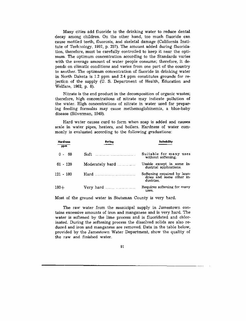
Many cities add fluoride to the drinking water to reduce denta ldecay among children . On the other hand, too much fluoride ca ncause mottled teeth, fluorosis, and skeletal damage (California Insti-tute of Technology, 1957, p . 257) . The amount added during fluorida-tion, therefore, must be carefully controlled to keep it near the opti-mum, The optimum concentration according to the Standards varie swith the average amount of water people consume; therefore, it de-pends on climatic conditions and varies from one part of the countryto another . The optimum concentration of fluoride in drinking wate rin North Dakota is 1 .2 ppm and 2 .4 ppm constitutes grounds for re-jection of the supply (U. S. Department of Health, Education an dWelfare, 1962, p . 8) .
Nitrate is the end product in the decomposition of organic wastes ;therefore, high concentrations of nitrate may indicate pollution o fthe water. High concentrations of nitrate in water used for prepar-ing feeding formulas may cause methemoglobinemia, a blue-babydisease (Silverman, 1949) .
Hard water causes curd to form when soap is added and cause sscale in water pipes, heaters, and boilers . Hardness of water com-monly is evaluated according to the following graduations :
Hardiness Rating Suitabilit y
PP"'
0 -
60 Soft Suitable for many use swithout softening.
61 - 120 Moderately hard Usable except in some in-dustrial applications .
121 - 180 Hard Softening required by laun-dries and some other in-dustries.
180- Very hard Requires softening for manyuses .
Most of the ground water in Stutsman County is very hard .
The raw water from the municipal supply in Jamestown con-tains excessive amounts of iron and manganese and is very hard . Thewater is softened by the lime process and is fluoridated and chlor-inated. During the softening process the dissolved solids are also re-duced and iron and manganese are removed. Data in the table below,provided by the Jamestown Water Department, show the quality o fthe raw and finished water .
5 1
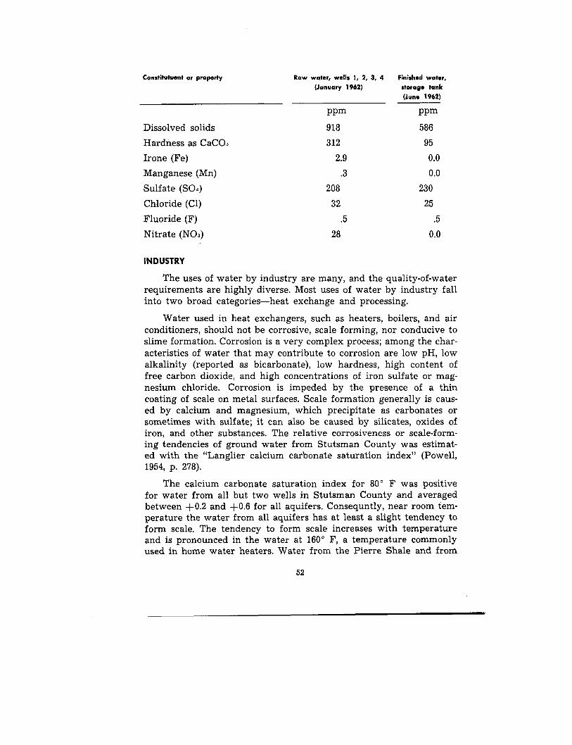
Constitutuent or property
Raw water, wells 1, 2, 3, 4
Finished water,(January 1962)
storage tan k
(June 1962 )
ppm ppm
Dissolved solids 918 58 6
Hardness as CaCO3 312 9 5
Irone (Fe) 2 .9 0 . 0
Manganese (Mn) .3 0 .0
Sulfate (SO4) 208 230
Chloride (Cl) 32 2 5
Fluoride (F) .5 . 5
Nitrate (NO3) 28 0 . 0
INDUSTRY
The uses of water by industry are many, and the quality-of-wate rrequirements are highly diverse. Most uses of water by industry fallinto two broad categories—heat exchange and processing .
Water used in heat exchangers, such as heaters, boilers, and ai rconditioners, should not be corrosive, scale forming, nor conducive t oslime formation . Corrosion is a very complex process ; among the char-acteristics of water that may contribute to corrosion are low pH, lo walkalinity (reported as bicarbonate), low hardness, high content o ffree carbon dioxide, and high concentrations of iron sulfate or mag-nesium chloride. Corrosion is impeded by the presence of a thi ncoating of scale on metal surfaces. Scale formation generally is caus-ed by calcium and magnesium, which precipitate as carbonates o rsometimes with sulfate ; it can also be caused by silicates, oxides ofiron, and other substances . The relative corrosiveness or scale-form-ing tendencies of ground water from Stutsman County was estimat-ed with the "Langlier calcium carbonate saturation index" (Powell ,1954, p . 278) .
The calcium carbonate saturation index for 80° F was positiv efor water from all but two wells in Stutsman County and average dbetween +0.2 and +0.6 for all aquifers . Consequntly, near room tem-perature the water from all aquifers has at least a slight tendency t oform scale . The tendency to form scale increases with temperatur eand is pronounced in the water at 160° F, a temperature commonlyused in home water heaters . Water from the Pierre Shale and from
52
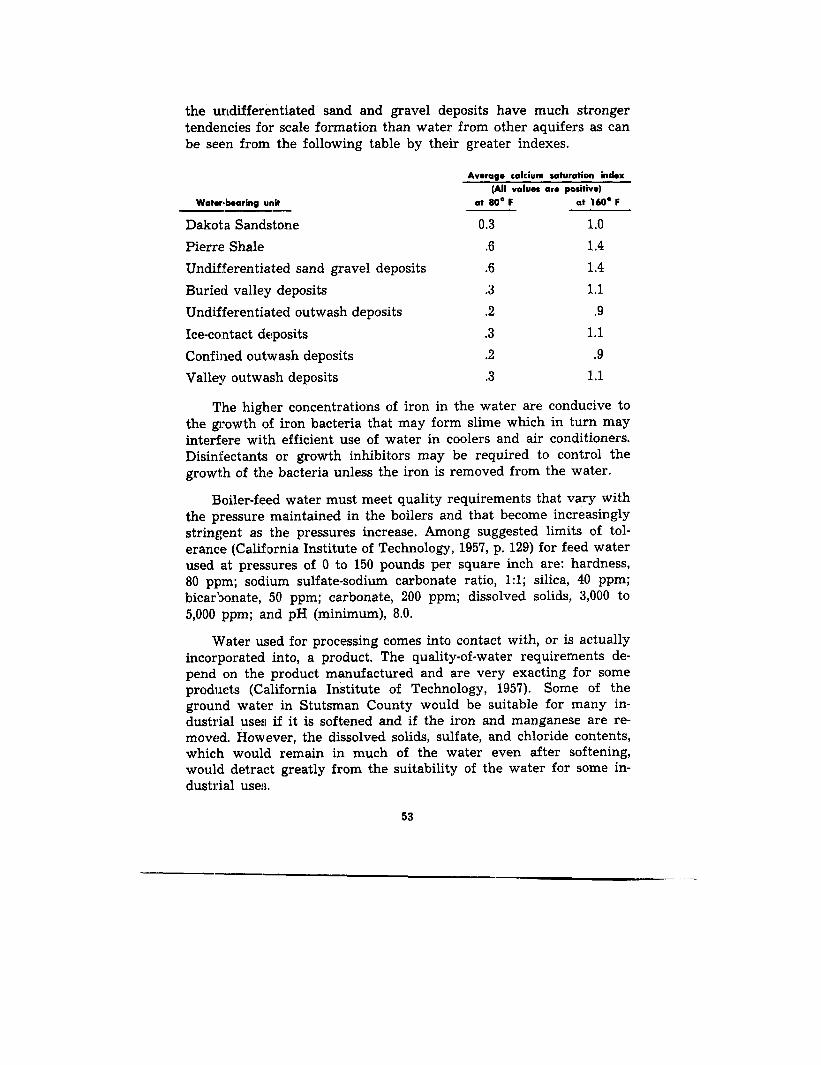
the undifferentiated sand and gravel deposits have much strongertendencies for scale formation than water from other aquifers as ca nbe seen from the following table by their greater indexes .
Average calcium saturation index(All values are positive)
Waterd»aring unit at 80° F at 160° F
Dakota Sandstone 0.3 1 . 0
Pierre Shale .6 1 . 4
Undifferentiated sand gravel deposits .6 1 . 4
Buried valley deposits .3 1 . 1
Undifferentiated outwash deposits .2 . 9
Ice-contact deposits .3 1 . 1
Confined outwash deposits .2 . 9
Valley outwash deposits .3 1 .1
The higher concentrations of iron in the water are conducive tothe growth of iron bacteria that may form slime which in turn ma yinterfere with efficient use of water in coolers and air conditioners .Disinfectants or growth inhibitors may be required to control th e
growth of the bacteria unless the iron is removed from the water .
Boiler-feed water must meet quality requirements that vary wit hthe pressure maintained in the boilers and that become increasingl y
stringent as the pressures increase . Among suggested limits of tol-erance (California Institute of Technology, 1957, p . 129) for feed wate rused at pressures of 0 to 150 pounds per square inch are : hardness ,
80 ppm; sodium sulfate-sodium carbonate ratio, 1 :1 ; silica, 40 ppm ;
bicarbonate, 50 ppm; carbonate, 200 ppm; dissolved solids, 3,000 to
5,000 ppm; and pH (minimum), 8 .0 .
Water used for processing comes into contact with, or is actuall yincorporated into, a product . The quality-of-water requirements de-pend on the product manufactured and are very exacting for someproducts (California Institute of Technology, 1957) . Some of theground water in Stutsman County would be suitable for many in-dustrial uses if it is softened and if the iron and manganese are re -moved. However, the dissolved solids, sulfate, and chloride contents ,which would remain in much of the water even after softening ,would detract greatly from the suitability of the water for some in-dustrial uses .
53
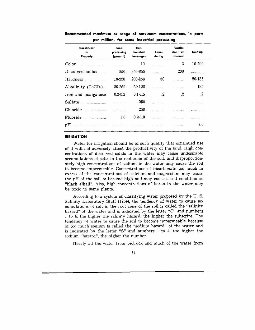
Recommended maximum or range of maximum concentrations, in parts
per million, for some industrial processing
Constituent
Food
Car-
Plastic sor
processing
bonated
Laun-
clear, un-
Tannin gProperty
(general)
beverages
dering
colore d
Color 10
2
10-100
Dissolved solids 850 850-855
20 0
Hardness 10-250 200-250
50 50-135
Alkalinity (CaCO3) .
30-250
50-128 135
Iron and manganese
0 .2-0 .3
0 .1-1 .5
.2
.2
.2
Sulfate 250
Chloride 250
Fluoride 1 .0
0 .2-1 .0
pH 8 . 0
IRRIGATIO N
Water for irrigation should be of such quality that continued us eof it will not adversely affect the productivity of the land . High con-centrations of dissolved solids in the water may cause undesirableaccumulations of salts in the root zone of the soil, and disproportion-ately high concentrations of sodium in the water may cause the soil
to become impermeable. Concentrations of bicarbonate too much i nexcess of the concentrations of calcium and magnesium may caus ethe pH of the soil to become high and may cause a soil condition a s"black alkali ". Also, high concentrations of boron in the water ma ybe toxic to some plants .
According to a system of classifying water proposed by the U. S.Salinity Laboratory Staff (1954), the tendency of water to cause ac -cumulations of salt in the root zone of the soil is called the "salinit yhazard" of the water and is indicated by the letter "C" and number s1 to 4; the higher the salinity hazard, the higher the subscript . Thetendency of water to cause the soil to become impermeable becaus eof too much sodium is called the "sodium hazard" of the water andis indicated by the letter "S" and numbers 1 to 4 ; the higher thesodium "hazard", the higher the number .
Nearly all the water from bedrock and much of the water fro m
54
undifferentiated sand and gravel deposits is either of the C4-S4 o rthe C4-S3 class ;; because of the very high salinity hazard and the hig hor very high sodium hazard, the water from these aquifers is of poorquality for irrigation. Some of the water from the undifferentiate dsand and gravel deposits and most of the water from the other Pleisto-cene drift aquifers are of either the C2-Sl or the C3-Sl class, hav eno excess of bicarbonate, and have low concentrations of boron . Thesewaters, therefore, are of fair to good quality for irrigation . Waterfrom some of the buried valley deposits, however, according to thetwo samples from the Spiritwood aquifer, may have excessive con-centrations of bicarbonate.
SUMMARYSources of ground water in Stutsman County are the Cretaceou s
bedrock formations and the Pleistocene glacial drift . The drift fur-nishes the most readily available and the largest ground-water sup -plies .
The bedrock formations that function as aquifers are the Dakot aSandstone and the Upper Cretaceous Pierre Shale . The shale is anaquifer only in its upper part where it is fractured or jointed . Thewater from the Dakota Sandstone has limited use because of it sdepth and high mineral content . The Pierre Shale furnishes som eground-water to many farms in Stutsman County, especially in areaswhere adequate supplies from the glacial drift are not available .
Glacial drift is the most important water-bearing material inStutsman County. It is a complex of materials that have a very lo wto high permeability and range in size from clay to boulders. Thedrift is classified as: (1) glaciofluvial, (2) glaciolacustrine, (3) buriedglacioaqueous, and (4) till . With the exception of till, the sedimenttypes are classified into two or more geohydrologic units on one o rmore of the following bases : lithology, associated landforms, positionin the drift, and water-bearing characteristics (table 2) .
The three major aquifers in Stutsman County are : (1) the James -town aquifer which consists of valley outwash deposits ; (2) the Mar-stonmoor Plain aquifer which consists of unconfined outwash de -posits; and (3) the Spiritwood aquifer which consists of buried valleydeposits . The Jamestown aquifer furnishes water to the city of James -town and several industries and institutions in Jamestown. The Mar-stonmoor Plain aquifer is virtually undeveloped as a source of ground -water supply, but its size and its assumed permeability indicate that
55
its water-yielding potential is equal to that of the Jamestown aquifer .The Spiritwood aquifer is buried under a thick cover of till and i sareally the largest aquifer in Stutsman County. It is tapped onlyby farm wells yielding supplies for domestic and stock uses . Its ca-pacity for furnishing large ground-water supplies is unknown, how -ever, its size and the coarseness of its sediments indicate that it is anexcellent aquifer .
Till greatly influences the occurrence and movement of groundwater in the drift . It is generally a tight, silty, clay with minor ad-mixtures of sand, gravel, cobbles, and boulders .
The dissolved-solids content of water from the Dakota Sandston eand of more than half the water from the Pierre Shale exceeded 2,000ppm. Most of the water from these Cretaceous deposits was very hardbut some from the Pierre was soft. Most of the water from the Dakot awas of the sodium sulfate type and most of the water from the Pierr ewas of the sodium chloride type .
Dissolved solids concentration in samples of water from undif-ferentiated sand and gravel deposits of Pleistocene age ranged fro m352 to 5,360 ppm, whereas that from surficial sand and gravel de-posits ranged from 332 to 1,190 ppm. Most of the water from deposit sof Pleistocene age is of the calcium bicarbonate type if the dissolve dsolids concentration is less than 1,300 ppm. If the dissolved solidsconcentration exceeds 1,300 ppm, most of the water is of calciumsulfate type .
The boron content of 1 to 5 ppm for water from the Dakota an dthe Pierre and the average fluoride content of 2 .4 ppm for wate rfrom the Dakota are significantly higher than the content of theseconstituents in water from other aquifers . Fluoride and boron con-tent of the water are helpful in distinguishing between waters frombedrock units and geohydrologic units of the drift .
Because of the high dissolved solids, iron, manganese, sulfate o rchloride contents of the water and because of the hardness, most ofthe ground water is of relatively poor quality for domestic, munici-pal, or industrial uses. However, softening and iron and manganeseremoval from water of surficial sand and gravel deposits, such a sthe valley outwash deposits used for municipal supply by Jamestown,results in water that is acceptable for most uses .
56
REFERENCES
Abbott, G . A. an.d Voedisch, F. W., 1938, The municipal ground-water suppliesof North Dakota : North Dakota Geol. Survey Bull. 11 .
Adolphson, D. G., 1961, Glacial drift aquifers in the Gackle area, Logan an dStutsman Counties, North Dakota : North Dakota Ground-Water Studie sNo. 33 .
Bradley, E ., Petri, L . R., and Adolphson, D. G., 1963, Geology and ground-waterresources of Kidder County, North Dakota, Part III, Ground water an dchemical quality of water : North Dakota Geol. Survey Bull. 36 andNorth Dakota State Water Commission County Ground Water Studies 1 .
California Institute of Technology, 1957, Water quality criteria: State WaterPollution Control Board pub . 3, 2d printing, 676 p.
Dennis, :P . E., 1948, Ground-water in the Wimbledon area, Barnes and Stuts-man Counties, North Dakota : North Dakota Ground Water Studies No . 10.
Flint, R. F ., 1957, Glacial and Pleistocene geology : New York, John Wiley andSons, Inc .
Hansen, D. E., 1955, Subsurface correlations of the Cretaceous Greenhorn-La-kota interval in North Dakota : North Dakota Geol . Survey Bull . 29 .
Hard, H. A., 1929, Geology and water resources of the Edgeley and LaMour eQuadrangles, North Dakota : U. S . Geol . Survey Bull . 801.
Hopkins, W. B., and Petri, L. R., 1963, Geology and ground-water resources ofthe Lake Dakota plain area, South Dakota : U. S . Geol . Survey Water-Supply Paper 1539-T.
Huxel, C . J . Jr., 1961, Artesian water in the Spiritwood buried valley complex ,North Dakota: U. S . Geol. Survey Prof. Paper 424-D, p. D-179-181 .
Huxel, C, J . Jr., and Petri, L . R., 1963, Geology and ground-water resourcesof Stutsman County, North Dakota, Part II, Ground-water basic data :North Dakota Geol . Survey Bull . 41 and North Dakota State WaterCommission County Ground Water Studies 2 .
Kelly, T. E., 1964, Geology and ground-water resources of Barnes County ,North Dakota, Part II, Ground-water basic data : North Dakota Geol.Survey Bull . 43 and North Dakota State Water Commission CountyGround Water Studies 4 .
Lemke, R. W., 1958, Glacial history of the Souris River lobe, North Dakota :North Dakota Geol . Survey Midwestern Friends of the Pleistocene 9thAnn. Field Conf. Guidebook, p . 41-57 .
Meinzer, O . E., 1923, Outline of ground-water hydrology with definitions :U. S . Geol . Survey Water-Supply Paper 494 .
Paulson, Q. F., 1952, Geology and occurrence of ground water in the Streeterarea, Stutsman, Logan, and Kidder Counties, North Dakota : North Da-kota Ground-Water Studies No . 20 .
, 1962, Ground water—a vital North Dakota resource: North DakotaGeol . Survey Miscellaneous Series No . 16, 26 p.
, 1962, Report on results of test drilling and pumping test in wildlif eresearch project area, James River valley, Stutsman County, North Da-kota: U. S . Geol. Survey open-file report, 18 p .
Powell, S. T., 1954,, Water conditioning for industry : McGraw-Hill Book Com-pany, Inc .
11111/1•11111P .ww.-11111111110wasmill
57

Rau, J . L., Bakken, W. E., Chmelik, J ., and Williams, B, J ., 1962, Geolog yand ground-water resources of Kidder County, North Dakota, Part I ,Geology: North Dakota Geol . Survey Bull. 36 .
Robinove, C . J ., Langford, R. H., and Brookhart, J. W., 1958, Saline-water re-sources of North Dakota : U. S . Geol. Survey Water-Supply Paper 1428, .
Silverman, L . B., 1949, Methemoglobinema: Report of two cases and clinicalreview: Journal-Lancet, v . 69, p . 94-97 .
Simpson, H . E., 1929, Geology and ground-water resources of North Dakotawith a discussion of the chemical character of the water, by H . B. Riffen-burg: U. S . Geol . Survey Water-Supply Paper 598 .
U . S . Department of Health, Education, and Welfare, 1962, Public Health Serv-ice drinking water standards : Public Health Service Pub. 956, Washing-ton Govt. Printing Office .
U. S . Salinity Laboratory Staff, 1954, Diagnosis and improvement of saline an dalkali soils : U. S. Dept . Agriculture, Agriculture Handbook 60, 160 p.
Wenzel, L . K. and Sand, H. H., 1942, Water supply of the Dakota Sandstone inthe Ellendale-Jamestown area, North Dakota : U. S. Geol . Survey Water-Supply Paper 889-A .
Willard, D. E., 1909, Jamestown-Tower folio no . 168 : Geol . Atlas of the U. S .Geol. Survey, 9 p.
Winters, H. A., 1961, Landforms associated with stagnant glacial ice : Prof.Geog., v . 13, p . 19-23 .
1963, Geology and ground-water resources of Stutsman County ,North Dakota, Part I, Geology, North Dakota Geol . Survey Bull . 41 .
58