coupled power transfer systems concepts...
TRANSCRIPT

Capacitively Coupled Power Transfer Systems Concepts & Opportunities
Dr. Dan Ludois
Assistant Professor, Electrical & Computer EngineeringUniversity of Wisconsin ‐Madison
University of Illinois Urbana ChampaignNovember 2, 2015

University of Wisconsin

A Little Group History
• Founded in 1981 – Prof. Don Novotny and Prof. Tom Lipo– 4 corporate sponsors
• Today– ~90 corporate sponsors (~$15k buy in)
• Flexible money, compliments federal grants– Individual sponsored projects case by case– 22 M.S. Students – on campus– 49 Ph.D. Students – on campus– 26 Distance Learning Graduate Students – off campus
• 34 years in power & energy research– power electronics, electric machines, grid applications
• MS Degrees granted: 364• PhD Degrees granted: 147
Prof. Don Novotny(Emeritus)
Prof. Tom Lipo(Emeritus)

Tenured Faculty
Prof. Giri Venkataramanan• Application of wide band-
gap devices
• Power converters for energy applications
• End-user power quality
• Microgrids
• Distributed generation for sustainable power
Prof. Tom Jahns• Electric machines,
especially PM machines
• Power conversion and control for distributed generation
• Microgrids
• Battery energy storage
Prof. Bob Lorenz• Physics-based control and
estimation methodologies
• Design for sensing, loss minimization, dynamic power conversion and observer-based sensor replacement
• Volt-second based control approaches
• Shaping fields for power semi sensor integration

Prof. Bulent Sarlioglu• Converters using wide band-
gap devices
• Electric machines
• High-speed electric machines and controls
• Axial flux machines
• Power converters for energy applications
Prof. Dan Ludois• Multi-level converters
• Wireless power transfer
• Capacitive power transfer
• New wound-field machine topologies
• Integrated L-C filters
• Electrostatic machines
Prof. Yehui Han• Resonant converters
• High frequency magnetic components
• Battery equalizers
• Multi-level converters
• Switched capacitor converters
• Integrated modular drives
Tenure‐Track Faculty

Research Projects
15
14
1312
0
5
10
15
20
25
30
Con
verte
rs
Con
trols
Mac
hine
s
Dev
ices
&M
ulti-
Phys
Inte
g
Pow
er S
ys

Why Wireless Power?
• Connector free• Increased reliability• No compatibility issues• Freedom of motion• Galvanic isolation• Access enclosed spaces

Wireless Power Transfer
• Large‐gap, coreless, inductive coupling
• Small‐gap, ferrous core, inductive coupling (gapped transformers)
• Electrostatic coupling, i.e. capacitive coupling
BPrimary
ElectronicsSecondary ElectronicsVin Vout
PrimaryElectronics
SecondaryElectronicsVin Vout
B
B
Magnetic field coupler
PrimaryElectronics
SecondaryElectronicsVin Vout
E
EElectric field coupler

Capacitive Power Transfer (CPT)
• CPT is the use of electric fields to transfer power and/or data across a boundary
• CPT provides galvanic isolation • CPT eliminates physical electrical contact (no connectors)• Electrically possible via:
– High frequency power electronics– Surface Area – Dielectric materials
PrimaryElectronics
SecondaryElectronicsVin Vout
E
EElectric field coupler

CPT Fundamentals
• What are the underlying physics that govern CPT?• How do we “push” power though a simple CPT system?
iC
Gap, d
Primary
A
Secondary
vC
Rload
E E
Primary
Secondary
dAC or

• Calculate vC for a sinusoidal iC:• Typically C is small, ~10s -100s pF
– High reactance– Results in high voltage
• If the gap field exceeds its dielectric strength, breakdown will occur!
• Calculate E by subbing in:
• The gap electric field:
CPT Fundamentals Cont.
Cjiv cC
c
or
C iA
jdvE
dAC or
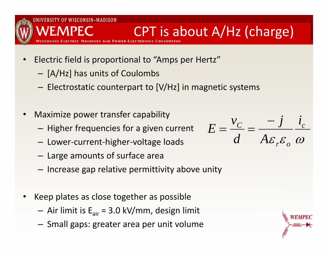
CPT is about A/Hz (charge)
• Electric field is proportional to “Amps per Hertz”– [A/Hz] has units of Coulombs– Electrostatic counterpart to [V/Hz] in magnetic systems
• Maximize power transfer capability– Higher frequencies for a given current– Lower‐current‐higher‐voltage loads – Large amounts of surface area– Increase gap relative permittivity above unity
• Keep plates as close together as possible– Air limit is Eair = 3.0 kV/mm, design limit– Small gaps: greater area per unit volume
c
or
C iA
jdvE

CPT Potential Advantages
Materials• Displace the use of Copper windings• Displace the use of Iron• Displace the use of Litz wire coils
These are replaced with:
• Thin Aluminum foil surfaces
Shielding• For small gaps with wide surface area, E‐fields largely cancel
outside the gap

CPT Beginnings
Nikola Tesla using the electric field of a parallel plate capacitor to drivefluorescent tube lighting, at Columbia University NY, May 20th 1891.online: http://en.wikipedia.org/wiki/File:TeslaWirelessPower1891.png

Low Power Applications
Culurciello and Andreou 2006 Piipponen, et al 2007
Byungcho, et al 2004Wahab, et al 1997
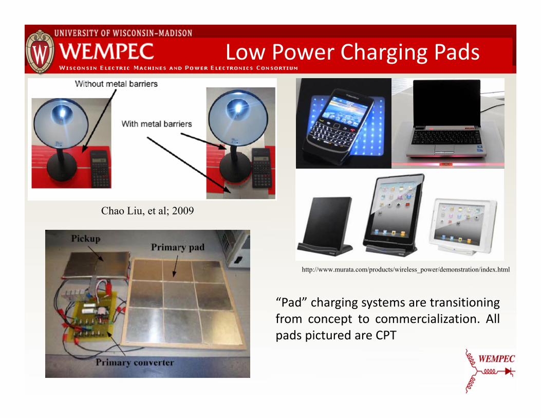
Low Power Charging Pads
“Pad” charging systems are transitioningfrom concept to commercialization. Allpads pictured are CPT
http://www.murata.com/products/wireless_power/demonstration/index.html
Chao Liu, et al; 2009

Low Power Vehicle Charging
A.P. Hu, et al; 2008
• Battery charging for mobile robots• Robot “backs up” to a wall with imbedded coupling plates• “Strip” or “ribbon” form factor

Brush & Slip Ring Replacement
L. Chao, A. P. Hu, and N. K. C. Nair, "Coupling study of a rotary Capacitive Power Transfer system," in Industrial Technology, 2009. ICIT 2009. IEEE International Conference on, 2009, pp. 1-6.
D. C. Ludois, K. Hanson, and J. K. Reed, "Capacitive power transfer for slip ring replacement in wound field synchronous machines," in Energy Conversion Congress and Exposition (ECCE), 2011 IEEE, 2011, pp. 1664-1669

Kilowatt Scale CPT
• 1kW to load, 90.1% efficient• 200kHz, 300V input• 12nF Coupling Cap
– ~200in2 Al foil – ~4mil Polypropylene dielectric
Jiejian Dai; Ludois, D.C., "Single Active Switch Power Electronics for Kilowatt Scale Capacitive Power Transfer," in Emerging and Selected Topics in Power Electronics, IEEE Journal of , vol.3, no.1, pp.315-323, March 2015

Large Gap Higher Power CPT
2.4kW system, large gap, 1MHz, 7.2 kVrms tank
Fei Lu; Hua Zhang; Hofmann, H.; Mi, C., "A Double‐Sided LCLC‐Compensated Capacitive Power Transfer System for Electric Vehicle Charging," in Power Electronics, IEEE Transactions on , vol.30, no.11, pp.6011‐6014, Nov. 2015
A. Kumar, S. Pervaiz, C.‐K. Chang, S. Korhummel, Z. Popovic, and K. K. Afridi, “Investigation of power transfer density enhancement in large air‐gap capacitive wireless power transfer systems,” in 2015 IEEE Wireless Power Transfer Conference (WPTC), 2015, pp. 1–4.
kW Scale Vehicle Concept
• Large air gap high power CPT systems are emerging, but serious safety concerns remain
• Low coupling capacitance requires High Voltage & Higher Frequency
•614 V/m for 0.03 – 1.34 MHz and falls with increasing frequency as 823.8/f V/m for 1.34 –30MHz“IEEE Standard for Safety Levels With Respect to Human Exposure to Radio Frequency Electromagnetic Fields, 3 kHz to 300 GHz,” IEEE Std C951‐2005 Revis. IEEE Std C951‐1991, pp. 0_1–238, 2006.

Survey of Published Work
• Compare CPT & IPT• >100 publications with
empirical results
Observations• Similar power levels• CPT<1mm gap• IPT>1mm gap• Similar power density• Frequencies differ
Jiejian Dai; Ludois, D.C., "A Survey of Wireless Power Transfer and a Critical Comparison of Inductive and Capacitive Coupling for Small Gap Applications," in Power Electronics, IEEE Transactions on , vol.30, no.11, pp.6017-6029, Nov. 2015

Survey of Published Work Cont.
Observations Continued• Coupling area is similar• Power‐frequency growing
– “Moore’s law like”– Advances due to
technologies like wideband gap devices
– Optimization – Packaging

CPT Research Community ThrustsIncrease power levels via:• Advanced power electronics
– Wide band gap semiconductors for high frequency– Minimal active components – Active and passive control techniques– Modular and pixilated architectures
• Surface area management– Surface (plate) alignment issues – Gap maintenance
– Flexible & Conformal Surfaces– Minimize Gap– Dielectric Materials (Solid & Fluid)

Applications to Explore
OK, so where can we deploy CPT?
Application 1: Slip Ring Replacement for Wound Field Synchronous Machines
Application 2: Conformal Bumper for Wireless Vehicle Charging
Both projects funded by DOE EERE Program

PM Machines for EV Traction
• Commercial & societal detractions of permanent magnet synchronous machines (PMSMs)
– Rare earth PMs are significant fraction of EV motor cost
– Rare earth PM market is volatile
– Rare earth PM extraction and refinement environmentally hazardous
– Rare earth PMs are largely single source from a foreign power

WFSMs for EV Traction
• PMSM’s operational detractions in a traction application‒ PMs have a fixed flux level, non variable, always “on”; safety
concerns during inverter faults.
– Interior PMSMs typically operate with negative d-axis current (especially during field weakening operation);
• Power factor lowered because of the reactive current
• Traction inverter oversized to supply reactive current
• Increased losses in inverter and stator (ohmic)
Wound Field Synchronous Machines (WFSM) stand to overcome the limitations of PMSMs via electromagnets

Rotor Excitation Techniques
7.5kW generator
CPT
Rotary transformer
Brushless Exciter
Brushes

IPT vs CPT Coupling for Machines
© Brusa 2004-2010 To Inverter
• Mechanical robustness (no windings, no ferrite, continuous surface)• Potential ease of manufacturing
Basic idea: replace PMs with electromagnets
Why CPT for this application?

Class E2 Converter
• Class E amplifier and rectifier, “class E2”• kW capable, 500kHz – 1MHz switching, 1200V SiC switches• Requires 2‐5 nF of coupling capacitance for C1, C2

Interleaved Configurations

Journal Bearing Coupling
• Journal style hydrodynamic bearing (GET THE GAP SMALL!)• Air gap space is constrained by OD & ID• Light weight oil working fluid• Simple construction, bidirectional rotation possible• Windage losses lend this configuration to smaller diameters

Journal Bearing Coupling
Sleeve journal version– Rotor rings are anodized AL
– Stator Rings are brass– Stator rings retained by silicone sleeve
– Designed for 1800rpm– Thermal image shows max temp of 36C.
Hagen, S.; Knippel, R.; Jiejian Dai; Ludois, D.C., "Capacitive coupling through a hydrodynamic journal bearing to power rotating electrical loads without contact," in Wireless Power Transfer Conference (WPTC), 2015 IEEE , vol., no., pp.1-4, 13-15 May 2015

Journal Capacitance vs. Speed
• Sleeve journal version• Hydrodynamic operation
established• Capacitance
asymptotically approaches steady state
• Coupling capacitance suitable for kW scale power transfer
• Track tank frequency for speed sensing
.
.

10kVA Generator Set Test
Field Voltage
Generator Output
Demo CPT on a machine2nd prototype sleeve coupling, all ALGenerator: 2 pole 10kVA
A simple CPT coupling solution, but… What if we want more capacitance per volume ?

Axial Flux Rotating Capacitors
Hub
Rotor Plate
Flexure
Stator Plate
Air
Air
Air
Air
• Axially stack thin plates• Spiral grooves on stators channel air into gaps• Air bearing action is established• Thin plates and flexures allow contouring
stator plate
rotor plate
Ludois, D.C.; Erickson, M.J.; Reed, J.K., "Aerodynamic Fluid Bearings for Translational and Rotating Capacitors in Noncontact Capacitive Power Transfer Systems," in Industry Applications, IEEE Transactions on , vol.50, no.2, pp.1025-1033, March-April 2014

Spiral Groove Hydrodynamics
34
1 , , , , , ,
, , , ,1
1
• Use Analytical techniques to get close• “Dial it in” with finite element• Finite element challenging, aspect ratio• Multi physics cross coupling• Need for further optimization Thrust Equations:
, ,cot 1 1
1 cot 1

Solid Rendering of Plates
• Spiral groove thrust bearing design, air is working fluid• Cascade as many plates as needed• 100mm diameter, 50 micron gap, 5 nF realized for C1 & C2

Rotor Plate Rendering
• 0.016in. thick 3003‐O Aluminum sheets• Hard anodized beyond flexures• Torque transmitted through featured I.D.
and nylon 6/6 alignment pins • 3003‐O• Resistivity – 3.649E‐8 [Ohm‐m]• Yield Strength – 144.78 [Mpa]• 6061‐T6• Resistivity – 4.066E‐8 [Ohm‐m]• Yield Strength – 241.31 [Mpa]
Φ 100mm
Φ 60mm

Stator Plate Rendering
• 0.016in. thick 3003‐O Aluminum sheets
• Designed as outwardly pumping spiral groove bearing
• Supported on flexure beams at OD
Φ 60mm
Φ 113mm
Φ 85mm

Stator & Rotor Plates
• Prototype hydroflex coupling plates• Stator ‐ left, Rotor – right• Outward pumping groove pattern on stator

Rotary Capacitor Dyne Stand
• 0.001” air gap (25 micron)• Smallest air gap maintained to
date. (previously 0.003”)

Plate Capacitance vs. Speed
• 3 rotors sandwiched between 4 stators, lift off functionality• Capacitance drops 32% between 0 and 10 krpm (speed sense)• Adjust flexure design to compensate for pressure
0
5E‐10
1E‐09
1.5E‐09
2E‐09
2.5E‐09
3E‐09
0 20 40 60 80 100 120
Measured Ca
pacitance [F]
Percent Rated Speed

Integration into EV Traction
Integration in progress with a 70kW, 3500rpm base, 12000rpm max, WFSM
Machine rotor and stator (above)
Capacitive coupling plates (left)

Application 2: EV Charging
• Can we extend rotating capacitors concepts to EV Charging?• What do we do about the gap? • Large gaps result in high voltage between transmitter and
receiver• Let’s keep the small gap, viable for fleet applications
• Mechanical tricks for small gaps & pads• Confine the field for safety, EMI, etc.

No Surface is truly flat!
• Like the rotation systems, use the dielectric to mechanically guide• Make the surfaces flexible and compressible!• A conformal bumper/pad

Conformal Bumper Docking
On the Wall
Insulation/dielectrics
Transmitter metal foil
Foam
Wall
On the vehicle
Vehicle body
Receiver metal foil

Rigid vs. Conformal Pad

Corbin Sparrow Implementation
• Aluminum foil strips adhered to car• Identical strips on bumper station• 4” foam rubber backing for station• Polyethylene insulation
Aside from foam thickness, all attributes match the benchtop model

EV Bumper Capacitance
0
5
10
15
20
0 0.5 1 1.5 2 2.5 3
EV: C1EV: C2
• The EV conformal bumper capacitance was sized to match the bench• Coupling capacitance was comparable• Power electronics development on bench, then vehicle deployment

Measured Performance
Parameter Class E2
on EVClass E2
on bench
Input 250V 4.73A (1183W)
240V 4.83A (1159W)
Output 173.9V 5.98A (1040W)
185.4V 5.76A (1068W)
Efficiency 88% 92%
500kHz operation, ~400V on coupling caps

Loss Distribution
• Proximity and skin effects • Current crowding at edges of plates• Distance corresponds to loss discrepancy between EV and Bench• Future versions optimized for higher frequency & power
• 1MHz +, 4‐6kW, different electronics architecture
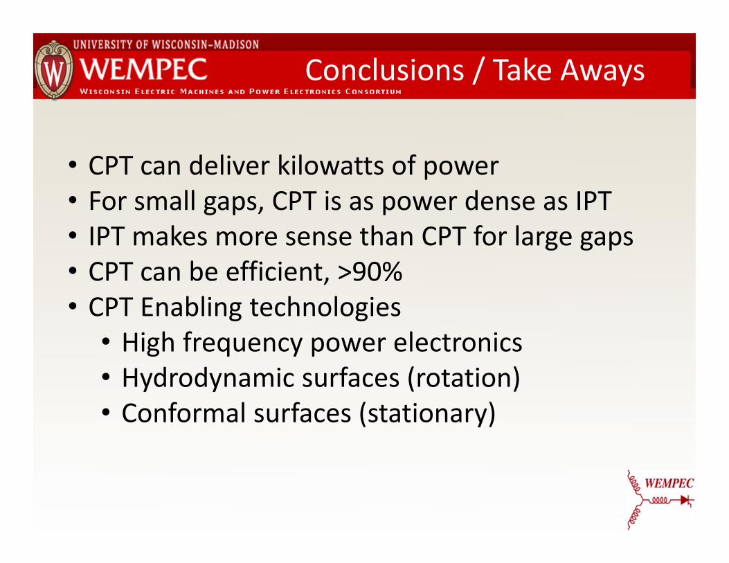
Conclusions / Take Aways
• CPT can deliver kilowatts of power• For small gaps, CPT is as power dense as IPT• IPT makes more sense than CPT for large gaps• CPT can be efficient, >90%• CPT Enabling technologies
• High frequency power electronics• Hydrodynamic surfaces (rotation)• Conformal surfaces (stationary)

Thank You!Q&A