course no: d04-001 credit: 4 pdh - ced engineering of steam traps.pdf · advantages of the inverted...
TRANSCRIPT

Overview of Steam Straps Course No: D04-001
Credit: 4 PDH
A. Bhatia
Continuing Education and Development, Inc. 9 Greyridge Farm Court Stony Point, NY 10980 P: (877) 322-5800 F: (877) 322-4774 [email protected]
Overview of Steam Traps
Steam traps are automatic valves used in every steam system to remove condensate,
air, and other non-condensable gases while preventing or minimizing the passing of
steam. If condensate is allowed to collect, it reduces the flow capacity of steam lines
and the thermal capacity of heat transfer equipment. In addition, excess condensate can
lead to “water hammer,” with potentially destructive and dangerous results. Air that
remains after system startup reduces steam pressure and temperature and may also
reduce the thermal capacity of heat transfer equipment. Non-condensable gases, such
as oxygen and carbon dioxide, cause corrosion. Finally, steam that passes through the
trap provides no heating service. This effectively reduces the heating capacity of the
steam system or increases the amount of steam that must be generated to meet the
heating demand.
No single steam trap is suitable for all steam distribution applications since the
condensate pressures and flow rates vary significantly at various points. As a result,
many different types of steam traps have been developed. The three major categories of
steam traps are 1) mechanical, 2) thermostatic, and 3) thermodynamic. In addition,
some steam traps combine characteristics of more than one of these basic categories.
______________________________________________________________________
Types of Steam Traps
There are three basic types of steam trap into which all variations fall. All three are
classified by International Standard ISO 6704:1984.

Group Principle Sub-group
Mechanical Trap This range of steam traps operates by
sensing the difference in density
between steam and condensate.
Bucket type
• Open bucket
• Inverted bucket with
lever, without lever
Float type
• Float with lever
• Free float
Thermodynamic Trap
This range of steam traps operate by
sensing difference in thermodynamic
properties between steam and
condensate.
Thermodynamic steam traps rely on
the fact that hot condensate, released
under dynamic pressure, will flash-off
to give a mixture of steam and water.
Disc type
Impulse type
Labyrinth type
Orifice type
Thermostatic Trap
This range of steam traps operate by
sensing difference in temperature
between steam and condensate.
Bimetallic type
Metal expansion type
Some of the important traps in industrial use are discussed below
Inverted Bucket Steam Trap
The inverted bucket trap is a mechanically actuated model that uses an upside down
bucket as a float. The bucket, connected to an outlet valve through a mechanical
linkage, sinks when condensate fills the steam trap; thereby, opening the outlet valve.
The bucket floats when steam enters the trap; thereby, closing the valve.

Advantages of the inverted bucket steam trap
1) The inverted bucket trap can be a very economical solution for low-to-medium
pressures applications such as plant heating and light-duty processes. When
handling high pressures and capacities, these traps become large and expensive.
2) Like a float-thermostatic steam trap, it has a good tolerance to water hammer
conditions
3) Can be used on superheated steam lines with the addition of a check valve on the
inlet
4) Failure mode is usually open, so it’s safer on those applications that require this
feature, for example turbine drains
Disadvantages of the inverted bucket steam trap
1) The small size of the hole in the top of the bucket means that this type of trap can
only discharge air very slowly. The hole cannot be enlarged, as steam would pass
through too quickly during normal operation.

2) Inverted bucket traps, as a group, are capable of handling a wide range of steam
pressures and condensate capacities. However, each specific steam trap handles a
very narrow range. An inverted bucket trap designed for 8.5 Kg/cm2 service operates
at pressures below this; however, its capacity is so diminished that it may “back up"
a system with unwanted condensate.
3) There should always be enough water in the trap body to act as a seal around the lip
of the bucket. If the trap loses this water seal, steam can be wasted through the
outlet valve. This can often happen on applications where there is a sudden drop in
steam pressure, causing some of the condensate in the trap body to 'flash' into
steam. The bucket loses its buoyancy and sinks, allowing live steam to pass through
the trap orifice. Only if sufficient condensate reaches the trap will the water seal form
again, and prevent steam wastage.
Important Guidelines for Inverted Bucket Traps
1) If an inverted bucket trap is used on an application where pressure fluctuation of the
plant can be expected, a check valve should be fitted on the inlet line in front of the
trap. Steam and water are free to flow in the direction indicated, while reverse flow is
impossible as the check valve would be forced onto its seat.
2) The higher temperature of superheated steam is likely to cause an inverted bucket
trap to lose its water seal. A check valve in front of the trap should be regarded as
essential under such conditions. Some inverted bucket traps are manufactured with
an integral check valve as standard.
3) The inverted bucket trap is likely to suffer damage from freezing, if installed in an
exposed position with sub-zero ambient conditions. Suitable insulation lagging can
overcome this problem, if conditions are not too severe. If ambient conditions well

below zero are to be expected, then it may be prudent to consider a more robust
type of trap to do the job. In the case of mains drainage, a thermodynamic trap would
be the first choice.
4) It is important to correlate the pressure rating and size with a specific application. For
example, an inverted bucket trap designed for up to 1 kg/cm2 service fails to operate
at pressures above 1 kg/cm2.
______________________________________________________________________
Float and Thermostatic Steam Trap
The ball float type trap operates by sensing the difference in density between steam and
condensate. The float and thermostatic (F&T) trap is a hybrid. As condensate collects, it
lifts a float which opens a valve as much as required. A built-in thermostatic element
purges air and other non-condensable gases and closes off when steam enters the trap.
This type of trap continuously drains the condensate as it forms.
Advantages of the float-thermostatic steam trap
1) The trap continuously discharges condensate as soon as it is formed. This makes it
the first choice for applications where the rate of heat transfer is high for the area of
heating surface available.

2) The F&T trap is able to purge the system of air and other non-condensable gases,
allowing for quick system startups.
3) It is able to handle heavy or light condensate loads equally well and is not affected
by wide and sudden fluctuations of pressure or flowrate.
4) The float valve with thermostatic air vent is resistant to water hammer and has large
capacity of its size.
Disadvantages of the float-thermostatic steam trap
1) Although less susceptible than the inverted bucket trap, the float type trap can be
damaged by severe freezing and the body should be well lagged, and / or
complemented with a small supplementary thermostatic drain trap, if it is to be fitted
in an exposed position.
2) As with all mechanical type traps, different internals are required to allow operation
over varying pressure ranges. Traps operating on higher differential pressures have
smaller orifices to balance the buoyancy of the float.
3) This type of trap is vulnerable to dirt in the system and the float ball can get damaged
by severe water hammer.
4) Similar to the inverted bucket trap, the F&T design handles a wide range of steam
pressures and condensate loads, in a group system. However, each individual trap
can only handle a very narrow range of pressures and capacities, making it critical to
exactly correlate the pressure rating and size to the application.
______________________________________________________________________

Thermodynamic Steam Trap
The thermodynamic trap has a simple mode of operation. The trap operates by means of
the dynamic effect of flash steam as it passes through the trap. Thermodynamic or disk
traps are designed with a flat disk which moves between a cap and seat. On startup,
condensate flow raises the disk and opens the discharge port. When steam or very hot
condensate arrives, it closes the disk, which stays closed as long as pressure is
maintained above the disk. Heat radiates out through the cap, which diminishes the
pressure over the disk, opening the trap to discharge condensate.
The rate of operation depends on steam temperature and ambient conditions. Most traps
will stay closed for between 20 and 40 seconds. If the trap opens too frequently, perhaps
due to a cold, wet, and windy location, the rate of opening can be slowed by simply
fitting an insulating cover onto the top of the trap.
Advantages of the thermodynamic steam trap
1) Thermodynamic traps can operate across their entire working range without any
adjustment or change of internals.
2) Thermodynamic traps are relatively small and compact for the amount of condensate
they are capable of discharging.

3) Thermodynamic traps can be used on high pressure and superheated steam and are
not affected by water hammer or vibration.
4) Thermodynamic traps are not damaged by freezing and are unlikely to freeze, if
installed with the disc in a vertical plane and discharging freely to atmosphere.
However, operation in this position may result in wear of the disc edge.
5) As the disc is the only moving part, maintenance can easily be carried out without
removing the trap from the line.
6) The audible 'click' which occurs as the trap opens and closes makes trap testing very
straight forward.
Disadvantages of the thermodynamic steam trap
1) Thermodynamic traps can discharge a large amount of air on start-up, if the inlet
pressure builds up slowly. However, rapid pressure build-up will cause high velocity
air to shut the trap in the same way as steam, and it will 'air-bind'. In this case a
separate thermostatic air vent can be fitted in parallel with the trap.
2) The primary disadvantage is difficulty in discharging air and other non-condensable
gases during rapid pressure build-up. The thermodynamic steam traps are though
available with an inbuilt anti-air-binding disc, which prevents air pressure building up
on top of the disc and allows air to escape.
3) Wear and dirt can be a problem with a disk trap because of the large, flat seating
surfaces involved. If pressure is not maintained above the disk, the trap cycles
frequently, wastes steam, and fails prematurely.
4) Thermodynamic steam traps will not work positively on very low differential
pressures.

5) The discharge of the trap can be noisy and this factor may prohibit the use of a
thermodynamic trap in noise sensitive areas. A diffuser may be needed to attenuate
the discharge noise.
6) Care should be taken not to oversize a thermodynamic trap as this can increase
cycle times and induce wear.
______________________________________________________________________
Thermostatic Steam Trap
Thermal element thermostatic traps are temperature actuated. On startup, the thermal
element is in a contracted position with the valve wide open purging air, condensate and
other non-condensable gases.
As the system warms up, heat generates pressure in the thermal element, causing it to
expand and throttle the flow of hot condensate through the discharge valve. When steam
follows the hot condensate into the trap, the thermal element fully expands, closing the
trap. If condensate enters the trap during system operation, it cools the element,
contracting it off the seat, and quickly discharging condensate. Thermostatic traps can
have either continuous or intermittent discharge depending upon the load.

Thermostatic traps are often considered a universal steam trap and are small,
lightweight, and compact. For light-to-moderately high condensate loads, thermostatic
steam traps offer advantages in terms of initial cost, long-term energy conservation,
reduced inventory, and ease in application and maintenance.
Single trap can operate over extremely broad pressure and capacity ranges. Thermal
elements can be selected to operate within a range of steam temperatures. In steam
tracing applications it may be desirable to actually back up hot condensate in the lines to
extract its thermal value.
These are normally not recommended for extremely high condensate requirements (over
7000 kg/hr).
The biggest disadvantage of the thermostatic traps is that they retain condensate until
cooled to below saturation temperature. Should this condensate remain in the steam
space, it would reduce the heat transfer area and the heater performance.
______________________________________________________________________
Bimetallic Steam Trap
Bimetallic steam traps operate on the same principle as a heating thermostat. A
bimetallic strip or wafer connected to a valve, bends or distorts when subjected to a
change in temperature. When properly calibrated, the valve closes off against a seat
when steam is present, and opens when condensate, air, and other non-condensable
gases are present.

There are two important points to consider regarding this simple element:
1. Operation of the steam trap takes place at a certain fixed temperature, which may
not satisfy the requirements of a steam system possibly operating at varying
pressures and temperatures.
2. Because the power exerted by a single bimetal strip is small, a large mass would
have to be used which would be slow to react to temperature changes in the steam
system.
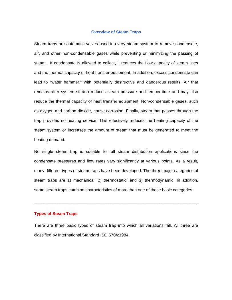
A simple bimetal element tends to react to temperature changes in a linear fashion. The
condensate is discharged below steam temperature, which will cause water logging of
the steam space unless the steam trap is fitted at the end of a long cooling leg (typically
1-3 meter of unlagged pipe). The figure below shows the general arrangement.
The flash steam produced whenever condensate is discharged from a higher to a lower
pressure will tend to cause an increase in backpressure in the condensate line. The
cooling leg allows the condensate to cool down, producing less flash steam in the
condensate line and thus helping to reduce the backpressure.
The condensate is discharged at varying temperatures below saturation temperature.
The maximum energy from the condensate is extracted before it drains to waste, and
this is why these traps are used on tracer lines where condensate is often dumped to
waste.
Bimetallic steam traps are not suitable for fitting to process plants where immediate
condensate removal is vital for maximum output to be achieved. This is particularly
relevant for temperature controlled plants.
Advantages of the bimetallic steam trap:
1) Advantages are their relatively small size for the condensate loads they handle.
2) Bimetallic steam traps are usually able to withstand water hammer, corrosive
condensate, and high steam pressures.

3) The valve is wide open when the steam trap is cold, giving good air venting capability
and maximum condensate discharge capacity under 'start-up' conditions.
4) As condensate tends to drain freely from the outlet, this type of steam trap will not
freeze up when working in an exposed position.
5) The bimetal elements can work over a wide range of steam pressures without any
need for a change in the size of the valve orifice.
6) Maintenance of this type of steam trap presents few problems, as the internals can
be replaced without removing the trap body from the line.
Disadvantages of the bimetallic steam trap:
1) A disadvantage is that the traps must be set, generally at the plant, for a particular
steam operating pressure. If the trap is used for a lower pressure, it may discharge
live steam. If used at a higher steam pressure, it can back up condensate into the
system.
2) Bimetallic steam traps do not respond quickly to changes in load or pressure
because the element is slow to react.
3) Some bimetallic steam traps are vulnerable to blockage from pipe dirt due to low
internal flow velocities.
4) If the bimetallic steam trap has to discharge against a significant backpressure, the
condensate must cool to a lower temperature than is normally required before the
valve will open. A 50% backpressure may cause up to a 50°C drop in discharge
temperature. It may be necessary to increase the length of cooling leg to meet this
condition.
______________________________________________________________________
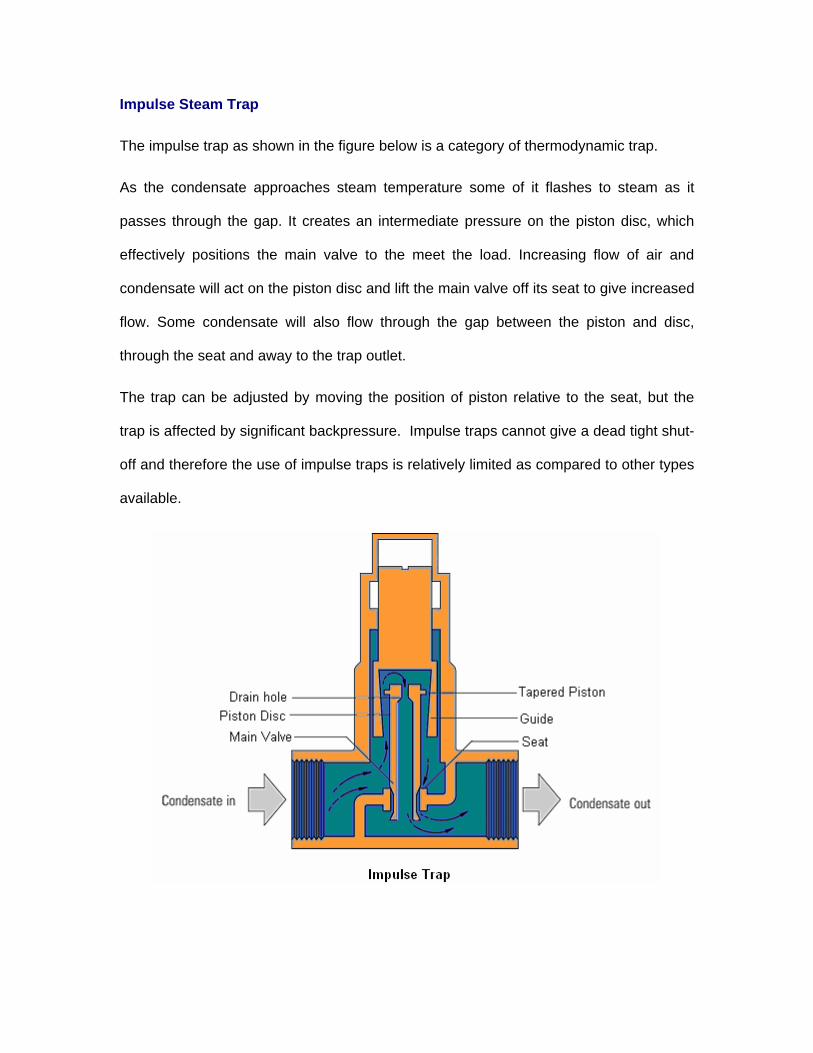
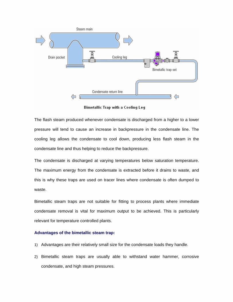
Impulse Steam Trap
The impulse trap as shown in the figure below is a category of thermodynamic trap.
As the condensate approaches steam temperature some of it flashes to steam as it
passes through the gap. It creates an intermediate pressure on the piston disc, which
effectively positions the main valve to the meet the load. Increasing flow of air and
condensate will act on the piston disc and lift the main valve off its seat to give increased
flow. Some condensate will also flow through the gap between the piston and disc,
through the seat and away to the trap outlet.
The trap can be adjusted by moving the position of piston relative to the seat, but the
trap is affected by significant backpressure. Impulse traps cannot give a dead tight shut-
off and therefore the use of impulse traps is relatively limited as compared to other types
available.

Advantages of the impulse steam trap
1) Impulse traps have a substantial condensate handling capacity for their size.
2) They will work over a wide range of steam pressures without any change in valve
size and can be used on high pressure and superheated steam.
3) They are good at venting air and cannot 'air-bind'.
Disadvantages of the impulse steam trap
1) Impulse traps cannot give a dead tight shut-off and will blow steam on very light
loads.
2) They are easily affected by any dirt which enters the trap body due to the extremely
small clearance between the piston and the cylinder.
3) The traps can pulsate on light load causing noise, water hammer and even
mechanical damage to the valve itself.
4) They will not work against a backpressure which exceeds 40% of the inlet pressure.
______________________________________________________________________
Labyrinth Steam Trap
A simple form of the labyrinth trap belongs to thermodynamic category. It consists of a
series of baffles which can be adjusted by means of a hand wheel. Hot condensate
passing between the first baffle and the trap body is subject to a drop in pressure and
some of it 'flashes' to steam. The space around the next baffle has to cope with an
increased volume of hot condensate and prevents the escape of live steam. The baffle
plates can be moved either in or out using the hand wheel, which alters their position
relative to the body, effectively altering the overall size of the orifice.

Advantages of the labyrinth steam trap
This type of trap is comparatively small in relation to its capacity and there is little
potential for mechanical failure since there are no automatic parts.
Disadvantages of the labyrinth steam trap
The labyrinth trap has to be adjusted manually whenever there is a significant variation
in either steam pressure or condensate load. If the setting is not right for the prevailing
conditions, steam wastage or water logging of the steam space will occur (like a fixed
orifice trap).
______________________________________________________________________
Fixed Orifice Steam Trap
These are devices containing a hole of predetermined diameter to allow a calculated
amount of condensate to flow under specific pressure conditions. In practice,
condensate loads and steam pressures can vary considerably between start-up and
running loads, for example,
o If sized on running load, fixed orifice traps will waterlog on start-up, reducing
plant performance over this period, increasing start-up times and the risk of
corrosion.

o If sized on start-up load, fixed orifice traps will waste steam when the plant is
running, and increase start-up times.
Fixed orifice traps are often blocked with dirt due to the small size of orifice and are not
recommended.
______________________________________________________________________
Considerations for Steam Trap Selection
The trap selection is based on the requirements of pressure, condensate load and air
venting.
Air venting: At 'start-up', the heater space is filled with air, which unless displaced, will
reduce heat transfer and increase the warm-up time. It is important to purge air as
quickly as possible before it has a chance to mix with the incoming steam, otherwise it
could increase production times, warm-up times and corrosion.
Separate air vents may be required on larger or more awkward steam spaces, but in
most cases air in the system is discharged through the steam traps. Here thermostatic
traps have a clear advantage over some types of trap since they are fully open at start-
up. Float traps with inbuilt thermostatic air vents are useful, while many thermodynamic
traps are also quite capable of handling moderate amounts of air. However, the small
hole in fixed orifice condensate outlets and the bleed hole in inverted bucket traps vent
air slowly.
______________________________________________________________________
Condensate removal: Having vented the air, the trap must then pass the condensate
but not the steam. Leakage of steam at this point is inefficient and uneconomical. The
steam trap has to allow condensate to pass while trapping the steam in the process. If
good heat transfer is critical to the process, then condensate must be discharged

immediately and at steam temperature. Water logging is one of the main causes of
inefficient steam plant as a result of incorrect steam trap selection.
______________________________________________________________________
Temperatures & Pressures: Before choosing a particular steam trap, it is necessary to
consider the needs of the process. The quantity of condensate a steam trap has to deal
with may vary considerably. It may have to discharge condensate at steam temperature
(i.e. as soon as it forms in the steam space) or it may be required to discharge below
steam temperature, giving up some of its 'sensible heat' in the process.
Steam traps may be subjected to extremes of temperature or even water hammer. The
pressures at which steam traps can operate may be anywhere from vacuum to well over
a hundred bar. To suit these varied conditions there are various choices, each having
their own advantages and disadvantages. Experience shows that steam traps work most
efficiently when their characteristics are matched to that of the application.
It is imperative that the correct trap is selected to carry out a given function under given
conditions. Whatever the conditions, correct steam trap selection is important to system
efficiency. Check with suppliers for your type of application. A table below gives general
guidelines.
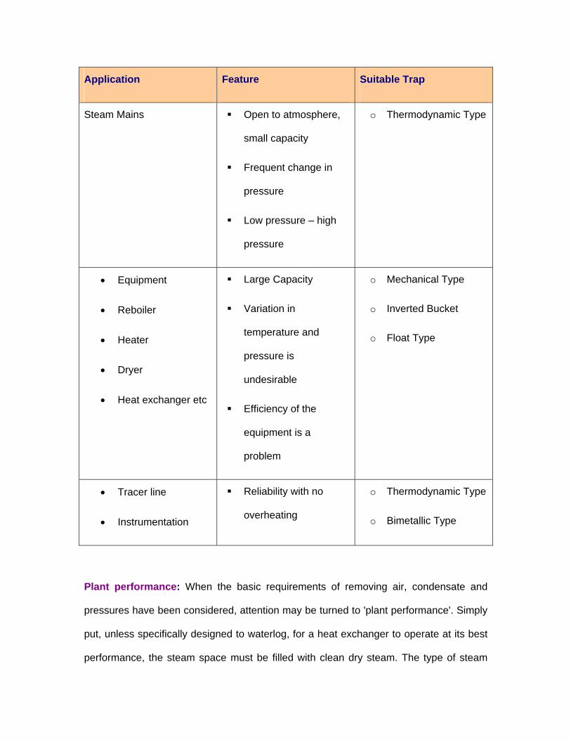
Application Feature Suitable Trap
Steam Mains Open to atmosphere,
small capacity
Frequent change in
pressure
Low pressure – high
pressure
o Thermodynamic Type
• Equipment
• Reboiler
• Heater
• Dryer
• Heat exchanger etc
Large Capacity
Variation in
temperature and
pressure is
undesirable
Efficiency of the
equipment is a
problem
o Mechanical Type
o Inverted Bucket
o Float Type
• Tracer line
• Instrumentation
Reliability with no
overheating
o Thermodynamic Type
o Bimetallic Type
Plant performance: When the basic requirements of removing air, condensate and
pressures have been considered, attention may be turned to 'plant performance'. Simply
put, unless specifically designed to waterlog, for a heat exchanger to operate at its best
performance, the steam space must be filled with clean dry steam. The type of steam

trap will influence this operation. For instance, thermostatic traps retain condensate until
cooled to below saturation temperature. Should this condensate remain in the steam
space, it would reduce the heat transfer area and the heater performance. The
discharge of condensate at the lowest possible temperature may seem very attractive,
but generally most applications require condensate to be removed from the steam space
at steam temperature. This needs a steam trap with different operating properties to the
thermostatic type, and this usually means either a mechanical or thermodynamic type
trap.
Once chosen, it is necessary to size the steam trap. This will be determined by the
system conditions and process parameters such as:
o Maximum steam and condensate pressures
o Operating steam and condensate pressures
o Temperatures and flow rates
o Whether the process is temperature controlled.
______________________________________________________________________
System Design Considerations & Installation Aspects
In most cases, trapping problems are caused by bad installation rather than by the
choice of the wrong type or faulty manufacture. To ensure a trouble-free installation,
careful consideration should be given to the drain point, pipe sizing, air venting, steam
locking, group trapping vs. individual trapping, dirt, water hammer, lifting of the
condensate, etc.
______________________________________________________________________
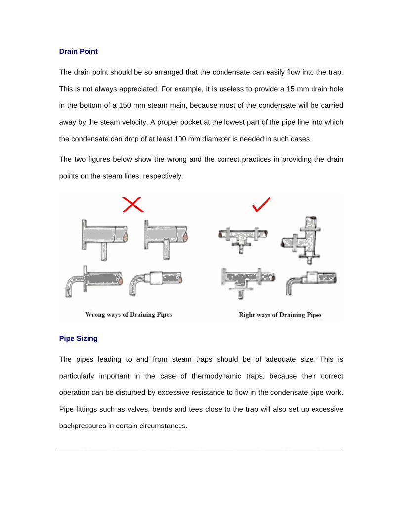
Drain Point
The drain point should be so arranged that the condensate can easily flow into the trap.
This is not always appreciated. For example, it is useless to provide a 15 mm drain hole
in the bottom of a 150 mm steam main, because most of the condensate will be carried
away by the steam velocity. A proper pocket at the lowest part of the pipe line into which
the condensate can drop of at least 100 mm diameter is needed in such cases.
The two figures below show the wrong and the correct practices in providing the drain
points on the steam lines, respectively.
Pipe Sizing
The pipes leading to and from steam traps should be of adequate size. This is
particularly important in the case of thermodynamic traps, because their correct
operation can be disturbed by excessive resistance to flow in the condensate pipe work.
Pipe fittings such as valves, bends and tees close to the trap will also set up excessive
backpressures in certain circumstances.
______________________________________________________________________

Air Binding
When air is pumped into the trap space by the steam, the trap function ceases. Unless
adequate provision is made for removing air either by way of the steam trap or a
separate air vent, the plant may take a long time in warming up and may never give its
full output.
______________________________________________________________________
Steam Locking
The possibility of steam locking can sometimes be a deciding factor in the selection of
steam traps. This is similar to air binding except that the trap is locked shut by steam
instead of air. It can occur whenever a steam trap is fitted remotely from the plant being
drained. It can become acute when condensate is removed through a siphon or dip pipe.
To relieve this problem a trap is provided with a 'steam lock release' valve. This is an
internal needle valve which allows the steam locked in the siphon pipe to be bled away
past the main valve. Because the needle valve is just open enough to avoid steam
wastage it has a limited capacity to vent air. Traps of this type are often provided with
combined air vents and steam lock release.
The typical example is a drying cylinder. It is always advisable to use a float trap
provided with a steam lock release arrangement. Other types of traps will open and
eventually cope with a steam lock; however, the drainage and plant performance will be
erratic. This is clearly unacceptable to users of process plant where batch times, quality
and efficiency are of high importance.
______________________________________________________________________

Group Trapping vs. Individual Trapping
Group trapping describes the use of one trap serving more than one application as
shown in figure below. This is known as group trapping. No doubt it saves money, but it
is rarely successful, since it normally causes water-logging and loss of output.
The steam consumption of a number of units is never the same at a moment of time and
therefore, the pressure in the various steam spaces will also be different. The figure
above shows two batch processes (jacketed pans) operating at two different steam
pressures with the drain line from each connected to one steam trap. The higher
pressure in plant B will allow condensate from this vessel to drain but will stop
condensate being discharged from plant A as check valve C will be held closed. Plant A
will waterlog and will suffer a severe drop in performance. Thus, the only satisfactory
arrangement would be to drain each steam space with its own trap and then connect the
outlets of the various traps to the common condensate return main as shown in the
figure below.

One possible application suitable for group trapping is an HVAC air handling unit with
multiple heater sections in series. The figure shows 3 steam coils fed with one control
valve. This 'flow' type application differs from the batch (or non-flow) process described
earlier. The heater sections will always share any load change as they are served by the
same control valve.

Note that this scheme will only work where all sections are fed by one control valve and
the same secondary fluid is being heated by all sections. In any case, with the low cost
of steam traps available today, it is always better for steam using equipment to be
trapped on an individual basis rather than on a group basis.
______________________________________________________________________
Dirt
Dirt is the common enemy of steam traps and the causes of many failures. Pipe dirt
created during installation contain scale, castings, weld metal, piece of packing and
jointing materials, etc. When the system has been in use for a while, the inside of the
pipe work and fittings, which are exposed to corrosive condensate, can get rusted. Thus,
rust in the form of a fine brown powder is also likely to be present. All this dirt will be
carried through the system by the steam and condensate until it reaches the steam trap.
Some of it may pass through the trap into the condensate system without doing any
harm, but some dirt will eventually jam the trap mechanism. It is advisable to use a
strainer positioned before the steam trap to prevent dirt from passing into the system.
Float-thermostatic steam traps are quite resistant to dirt due to the low velocity flow
through a relatively large orifice.
______________________________________________________________________
Water Hammer
Water hammer is a symptom of a problem in the steam system. This could be due to
poor design of the steam and condensate pipe work, the use of the wrong type of
trap(s), a leaking steam trap, or a combination of these factors.
A water hammer in a steam system is caused by condensate collection in the plant or
pipe work picked up by the fast moving steam and carried along with it. When this
collection hits obstructions such as bends, valves, steam traps or some other pipe
fittings, it is likely to cause severe damage to fittings and equipment and result in leaking
pipe joints.
Water hammer can be caused in a number of ways, including:
o Failure to remove condensate from the path of high velocity steam in the pipe
work
o From an application which is temperature controlled and where condensate has
to lift to a return line, or return to a pressurized system
o The inability of condensate to properly enter or travel along an undersized return
line, due to either flooding or over-pressurization with the throttling effects of flash
steam.
The problem of water hammer can be eliminated by positioning the pipes so that there is
a continuous slope in the direction of flow. A slope of at least ½” (12 mm) in every 10 ft
(3 m) is necessary, as also an adequate number of drain points every 100 to 150 ft (30
to 50 m) with adequately sized drain pockets. The bottom of any riser must also be
drained.
If a steam trap persistently fails on an established system due to water hammer, it is
probably the fault of the system layout, rather than the trap. It is important that the pipe
work is designed and installed correctly. This will help to maintain thermal performance
of the system throughout its service life.
______________________________________________________________________
Steam trap drainage of temperature controlled processes
The steam trap is an automatic valve that relies on the system dynamics to provide flow.
It has to rely on and react to external factors, such as steam pressure or static head

pressure on the inlet side of the trap. The outlet pressure must be lower than the inlet
pressure to provide flow in the correct direction. The rate of flow through any steam trap
is therefore related to the differential pressure across it.
It is also possible to have negative differential pressures across the trap, which would
promote reverse flow through it. When traps are installed to pass condensate into
common return lines, it is advisable to fit non-return valves after each trap to prevent
reverse flow under negative pressure conditions.
The occurrence of zero and negative differential pressure across steam traps is
commonplace. The effects are commonly seen with temperature controlled processes
i.e. heater batteries, calorifiers, jacketed pans, plate heat exchangers, in fact any
process that has a control valve on the steam supply. It can occur irrespective of steam
supply pressure, and depends wholly on the condensate system pressure and the steam
pressure in the heat exchanger.
Whenever it is predicted or diagnosed, another solution, such as a pump-trap is required
to remove the condensate from the heat exchanger.
______________________________________________________________________
Lifting the condensate
In the interest of energy and treated water savings, every effort should be made to
recover and re-use the condensate. Generally, this means lifting the condensate into a
return main above the equipment. There may also be a case where the layout of the
plant dictates that the steam traps be fitted above the equipment being drained. Wrong
installation can lead to trouble. Because of the backpressures imposed upon the steam
trap, it is often better not to lift the condensate directly from the trap, but to let it flow by
gravity to a pump or a pumping trap, which can then do the lifting. However, if it is

decided that the condensate has to be lifted by its own pressure at the trap, it is
important to ensure that the installation is correctly arranged. The figure below shows a
desirable arrangement of condensate draining and lifting. The rising pipe coil is looped to
form a water seal. A small bore pipe is then passed through a steam tight joint at the top
of the rising pipe, and its end is pushed well into the loop seal. The trap is fitted as close
to the top of this pipe as possible. The water seal now makes it near impossible for the
steam to enter the pipe leading up to the trap, and the small bore of this pipe ensures
that the water column rises steadily due to steam bubbles.
Special requirements (Vacuum drainage)
Condensate removal from a steam space working under vacuum can be a problem. If a
steam trap is used, its outlet must be connected to a source of greater vacuum than that
in the steam space to ensure a constant differential pressure across the orifice to
discharge the condensate. Where this is not possible, a pressure powered pump can be
used to drain condensate from the plant.

A soft seated check valve is recommended on the pump outlet where little or no lift is
present, and an air break will act as an anti-siphoning device when draining to a point
below the pump.
Should the pump be draining condensate from a vacuum gas system then compressed
air or inert gas can be used as the motive force to drive the pump.
______________________________________________________________________
Maintenance of Steam Traps
Dirt is one of the most common causes of steam traps blowing steam. Dirt and scale are
normally found in all steam pipes. Bits of jointing material are also quite common. Since
steam traps are connected to the lowest parts of the system, sooner or later this foreign
matter finds its way to the trap. Once some of the dirt gets logged in the valve seat, it
prevents the valve from shutting down tightly thus allowing steam to escape. The valve
seal should, therefore, be quickly cleaned to remove this obstruction and thus prevent
steam loss.
In order to ensure proper working, steam traps should be kept free of pipe-scale and dirt.
The best way to prevent the scale and dirt from getting into the trap is to fit a strainer.

Strainer is a detachable, perforated or meshed screen enclosed in a metal body. It
should be borne in mind that the strainer collects dirt in the course of time and will
therefore need periodic cleaning. It is of course, much easier to clean a strainer than to
overhaul a steam trap.
______________________________________________________________________
Routine maintenance
In most industries, maintenance of steam traps is not a routine job and is neglected
unless it leads to some definite trouble in the plant. In view of their importance as steam
savers and to monitor plant efficiency, the steam traps require considerably more care
than is given. One may consider a periodic maintenance schedule to repair and replace
defective traps in the shortest possible time, preferable during regular maintenance shut
downs.
Routine maintenance depends on the type of trap and its application. The steam trap
must be checked from time to time and any routine maintenance should include the
renewal of any suspect parts, if it is to be cost effective.
The elements of thermostatic traps can generally be changed by removing a screwed in
seat. Replacement is simple and the remade trap will be reliable assuming the
maintenance instructions are correctly carried out.
The weakest point is often the joint between trap body and seat, particularly if this has
been allowed to blow steam. If the seat or disc faces of a thermodynamic trap become
damaged, the disc can simply be replaced. Damage to seating faces can be rectified by
lapping gently. Replacing the seats of some higher pressure thermodynamic traps is
more complicated.

Always check with the manufacturer regarding the correct technique for any
maintenance work required on steam traps.
______________________________________________________________________
Replacement of traps
On occasions, it will be easier and cheaper to replace traps rather than repair them. In
these cases it is essential that the traps themselves can be changed easily. Flanged
connections provide one solution, although the flanged trap is more expensive than the
equivalent screwed trap. Mating flanges are an additional expense. A swivel connector
allows rapid easy removal and replacement of the sealed trap.
______________________________________________________________________
Performance Testing of Steam Traps
Steam trap performance assessment is basically concerned with answering the two
questions:
1) Is the trap working correctly or not?
2) If not, has the trap failed in the open or closed position?
Traps that fail ‘open’ result in a loss of steam and its energy. Where condensate is not
returned, the water is lost as well. The result is significant economic loss, directly via
increased boiler plant costs, and potentially indirectly, via decreased steam heating
capacity.
Traps that fail ‘closed’ do not result in water losses, but can result in significantly
reduced heating capacity and/or damage to steam heating equipment.
A major problem has always been the accurate identification of faulty traps. Wrong
diagnosis can allow faulty traps to remain troublesome, and perfectly sound traps to be
replaced unnecessarily. Accurate diagnosis is therefore important to any maintenance
program.
Various diagnostic methods have included listening devices, optical sight glasses,
temperature monitoring, and ultrasonic techniques. All of these can give an indication of
flow, but become inaccurate as system conditions change.
______________________________________________________________________
Sight glasses: Sight glasses are useful in ascertaining the proper functioning of traps
and in detecting leaking steam traps. In particular, they are of considerable advantage
when a number of steam traps are discharging into a common return line. If it is
suspected that one of the traps is blowing steam, it can be quickly identified by looking
through the sight glass.
Sight glasses offer a partial solution, especially the combined sight/check valve that
gives a visual indication of flow plus a non-return facility, however, glasses will require
changing occasionally.
______________________________________________________________________
Sound Method: Mechanisms within steam traps and the flow of steam and condensate
through steam traps generate sonic (audible to the human ear) and supersonic sounds.
However, noise level will vary with disturbance from adjacent traps, and condensate
load. Interpretation of signals is difficult even for experienced operators. Proper listening
equipment, coupled with the knowledge of normal and abnormal sounds, can yield
reliable assessments of steam trap working condition. Listening devices range from a
screwdriver or simple mechanic's stethoscope that allow listening to sonic sounds.
A modern version of the listening rod is the ultrasonic trap tester which detects
ultrasound generated by a leaking trap. It is, unfortunately, unable to differentiate

between live steam and flash steam passing through the trap. It is also unable to detect
the subtle differences explained above.
______________________________________________________________________
Temperature Method: Saturated steam and condensate exist at the same
temperature. So it's not possible to distinguish between the two based on temperatures.
Still, temperature measurement provides important information for evaluation purposes.
A cold trap (i.e., one that is significantly cooler than the expected saturated steam
temperature) indicates that the trap is flooded with condensate, assuming the trap is in
service. On the other hand, the temperature downstream of the trap will be nearly
constant, if significant steam is getting past the trap.
As it is perfectly feasible for condensate and steam to coexist at the same temperature
in the same system, it makes accurate diagnosis difficult on temperature alone.
For hydrocarbon and processing industries that requires continuous monitoring of
processes, an integrated steam trap testing device consisting of a sensor, fitted inside
the steam trap, and capable of detecting the physical state of the medium at that point
by conductivity, is a reliable method to predict blockages. It is not affected by flash
steam disturbance. The result is finite and not subject to interpretation. The sensors can
be integral to the trap or are available in separate sensor chambers.
______________________________________________________________________
Conductivity Method: Conductivity-based diagnostics are based on the difference in
conductivity between steam and condensate. A conductivity probe is integrated with the
steam trap or just upstream of the steam trap in a sensing chamber. Under normal
operation, the tip of the conductivity probe is immersed in condensate. If the steam trap
leaks excessively or is blowing, steam flow will sweep away the condensate from the
test probe tip, and conductivity corresponding to steam will be measured.
Conductivity measurement must be accompanied by temperature measurement to
ensure a correct diagnosis. For example, an indication of steam and a trap that has
failed open could occur if a trap has not been used recently and has filled with air. The
conductivity of air is similar to steam, but a trap filled with air would be close to ambient
temperature, in contrast to a trap filled with steam. Similarly, the presence of condensate
could mean the trap is working properly, but could also mean that 1) the trap has
flooded, either because the trap has failed closed or something else is blocking the line,
2) the trap is undersized, or 3) the heat transfer equipment served by the trap is warming
up to its normal operating temperature and generating an unusually large amount of
condensate for a short period. These alternative conditions would be indicated by low
temperature in conjunction with the presence of condensate.
______________________________________________________________________
Energy Assessment of Steam Traps
The international standard ISO 7841 describes a reliable and accurate test methodology
for losses from any type of steam trap. Energy can be lost through the trap but this may
depend on size, type and the load. The energy loss is primarily at no load conditions and
is negligible as the condensate load increases. Energy will be lost from the trap due to
radiation but this can be reduced considerably by lagging.
A comparison of the inherent energy requirements of the main steam traps is as follows:
Thermostatic steam traps
Under normal operating conditions, the thermostatic trap holds back condensate until it
has cooled to a certain temperature. Steam does not reach the main valve so there is no

apparent steam wastage. However, water logging of plant can lead to reduced output
and extended operating times. More steam may be required although this will not appear
as an energy requirement attributable to the steam trap.
In some cases a cooling leg may be incorporated so that the steam space is kept clear
of condensate. Energy is thereby lost due to radiation from the cooling leg and from the
trap body. This in itself creates an additional condensate load, but there is no passage of
live steam through the trap.
The situation can change under no-load conditions. Heat loss from the trap body cools
the condensate surrounding the element which then opens. The minimal amount of
condensate involved is discharged and is then replaced by steam. Laboratory tests
indicate typical losses up to 0.5 kg/hr. Any attempt to lag a thermostatic trap will result in
a serious delay in the opening of the trap. Severe water logging will result and hence
lagging is not recommended for thermostatic traps.
______________________________________________________________________
Mechanical steam traps
The float-thermostatic trap is another example where the valve and seat are normally
flooded and there is no steam loss through the trap. Conversely, the float-thermostatic
trap is relatively large in size, and there may be a noticeable loss from the trap caused
by radiation.
The float-thermostatic trap can be lagged to reduce heat losses and this will not affect its
operation. Insulation lagging is normally recommended on outdoor applications to
minimize the danger of damage due to freezing when steam might be turned off.
The inverted bucket trap has surprisingly little in common with the float type trap. The
trap closes when steam enters and bubbles through into the bucket to make it buoyant.

It will not open until the steam has been dissipated. This will occur as the steam leaks
away through the hole in the bucket which serves as an air vent. The steam will collect
on the top of the trap itself and when the main valve opens, this steam is vented.
Laboratory tests indicate losses of around 0.5 kg/h for ½" traps under these low load
conditions. However, there is additional radiation loss from the body, which can be quite
large. Lagging is sometimes recommended but the heat loss and its resulting
condensate will be much the same as an equivalent float type trap.
______________________________________________________________________
Thermodynamic steam traps
The thermodynamic trap has the great simplicity in that it either works correctly or fails.
The operation depends on condensate approaching steam temperature, producing flash
steam at the orifice and causing the trap to close. It does this with condensate on the
upstream side and again the flooded valve means that there can be no loss through the
trap. However the trap will open periodically as heat is lost from the cap.
Under no-load conditions, i.e. when condensate is being produced only by heat loss
from the upstream pipeline, the condensate on the upstream side may exhaust and the
trap will then require a small amount of live steam to cause it to close. Much will depend
on ambient conditions but the loss will generally be around 0.5 kg/h and this could be
doubled in severe weather. The tests have shown that radiation losses are not more
than 0.25 kg/h which is at least a quarter of that experienced by equal sized inverted
bucket traps. Conversely, such losses can be halved by simply fitting an insulating cover
over the top cap.
______________________________________________________________________

Energy Saving Opportunities
Monitoring Steam Traps
For testing a steam trap, there should be an isolating valve provided in the downstream
of the trap and a test valve shall be provided in the trap discharge. When the test valve
is opened, the following points have to be observed:
1) Condensate discharge - Inverted bucket and thermodynamic disc traps should have
intermittent condensate discharge. Float and thermostatic traps should have a
continuous condensate discharge. Thermostatic traps can have either continuous or
intermittent discharge depending upon the load. If inverted bucket traps are used for
an extremely small load, it will have a continuous condensate discharge.
2) Flash steam -This shall not be mistaken for a steam leak through the trap. The users
sometimes get confused between a flash steam and leaking steam. The flash steam
and the leaking steam can be approximately identified as follows:
If steam blows out continuously in a blue stream, it is a leaking steam.
If a steam floats out intermittently in a whitish cloud, it is a flash steam.
Continuous steam blow and no flow indicate there is a problem in the trap. Whenever
a trap fails to operate and the reasons are not readily apparent, the discharge from
the trap should be observed. A step-by-step analysis has to be carried out mainly
with reference to lack of discharge from the trap, steam loss, continuous flow,
sluggish heating, to find out whether it is a system problem or the mechanical
problem in the steam trap.
______________________________________________________________________
Avoiding Steam Leakages
Failed steam traps can be a source of steam leakage that must be avoided. Just to give
a glimpse of energy loss, a 3 mm diameter hole on a pipeline carrying 7kg/cm2
Steam
would waste 33 KL of fuel oil per year. Steam leaks on high-pressure mains are
prohibitively costlier than on low pressure mains. Any steam leakage must be quickly
attended to. In fact, the plant should consider a regular surveillance program for
identifying leaks through the traps. Indeed, by plugging all leakages, one may be
surprised at the extent of fuel savings, which may reach up to 5% of the steam
consumption in a small or medium scale industry or even higher in installations having
several process departments.
To avoid leaks it may be worthwhile considering replacement of all defective steam
traps. The payback is very quick usually less than a year.
______________________________________________________________________
Providing Dry Steam for Process
The best steam for industrial process heating is the dry saturated steam. Wet steam
reduces total heat in the steam. Also water forms a wet film on heat transfer and
overloads traps and condensate equipment. Super heated steam is not desirable for
process heating because it gives up heat at a rate slower than the condensation heat
transfer of saturated steam.
It must be remembered that a boiler without a superheater cannot deliver perfectly dry
saturated steam. At best, it can deliver only 95% dry steam. The dryness fraction of
steam depends on various factors, such as the level of water to be a part of the steam.
Indeed, even as simple a thing as improper boiler water treatment can become a cause
for wet steam.

As steam flows through the pipelines, it undergoes progressive condensation due to the
loss of heat to the colder surroundings; the extent of the condensation depends on the
effectiveness of the lagging. For example, with poor lagging, the steam can become
excessively wet.
Since dry saturated steam is required for process equipment, due attention must be paid
to the boiler operation and lagging of the pipelines. In addition to placing steam traps
throughout the distribution network, a steam separator may be installed on the steam
main as well as on the branch lines to reduce wetness in steam and improve the quality
of the steam going to the units. By change of direction of steam, steam separators
causes the entrained water particles to be separated out and delivered to a point where
they can be drained away as condensate through a conventional steam trap.
______________________________________________________________________
Flash steam
An effect caused by passing hot condensate from a high pressure system to a low
pressure system is the naturally occurring phenomenon of flash steam. This can confuse
the observer regarding the condition of the steam trap.

The low pressure steam produced is usually referred to as 'flash steam'. The amount of
‘flash’ steam released can be calculated by the following relation with the help of steam
tables:
Flash Steam Available % = (S1- S2) / L2
Where
• S1 is the sensible heat of higher pressure condensate
• S2 is the sensible heat of the steam at lower pressure (at which it has been
flashed)
• L2 is the latent heat of the flash steam (at lower pressure)
If the trap was discharging 500 kg/h of condensate at 7barg to atmosphere, the amount
of flash steam generated would be 500 x 0.134 = 67 kg/h, equivalent to approximately
38 kW of energy loss.
This represents quite a substantial quantity of useful energy, which is all too often lost
from the heat balance of the steam and condensate loop, and offers a simple opportunity
to increase system efficiency if it can be captured and used.
______________________________________________________________________
Reliability
Reliability of good steam trapping means optimum performance with minimum attention.
Causes of unreliability are often associated with the following:
o Corrosion is a main concern due to the impurities and dissolved gases (CO2) of
the condensate. This can be countered by using particular materials of
construction, and good feed water conditioning.

o Water hammer often due to a lift after the steam trap, sometimes overlooked at
the design stage, and often the cause of unnecessary damage to otherwise
reliable steam traps.
o Dirt accumulating from a system where water treatment compound is carried
over from the boiler, or where pipe debris is allowed to interfere with trap
operation.
______________________________________________________________________
Codes and Standards
The international codes and standards applicable to the steam traps are listed below:
ISO 6552: 1980: Glossary of technical terms for automatic steam traps
ISO 6553: 1980: Marking of automatic steam traps
ISO 6554: 1980: Face-to-face dimensions for flanged automatic steam traps
ISO 6704: 1982: Classification of automatic steam traps
ISO 6948:1981: Production and performance characteristic tests for steam traps
ISO 7841: 1988: Methods for determination of steam loss of automatic steam traps
ISO 7842: 1988: Methods for determination of discharge capacity of steam traps
______________________________________________________________________
Summary
The job of the steam trap is to get condensate, air and non-condensable gases out of
the system as quickly as they accumulate. In addition, for overall efficiency and
economy, the trap must also minimize steam loss and provide dependable service.
Air can be present in steam at any time and especially on start-up. Air must be vented
for efficient heat transfer and to prevent system binding.
Efficient steam trapping will result in optimum efficiency and will achieve the following:
1) Fast heat-up of heat transfer equipment

2) Maximum equipment temperature for enhanced steam heat transfer
3) Maximum equipment capacity
4) Maximum fuel economy
5) Reduced labor per unit of output
6) Minimum maintenance and a long trouble-free service life
Efficient removal of CO2 from the condensate prevents the steam distribution network
and boiler from corrosion, while reducing the costs on water treatment chemicals.
______________________________________________________________________