course structure - b.tech 4 year degree course first year
TRANSCRIPT

Course Structure - B.Tech 4 Year Degree Course
First Year I - Semester
Code Subject name
Instruction periods per
week Max marks
Credits
Cat L T P Total Sessional End
marks
ECE111 English HS 3 1 - 4 40 60 3
ECE112 Engineering Mathematics I BS 3 1 - 4 40 60 3
ECE113 Engineering Chemistry BS 3 1 - 4 40 60 3
ECE114 Professional Ethics &
Human Values
HS 2 1 - 3 100 - 2
ECE115 Engineering Physics BS 3 1 - 4 40 60 3
ECE116 Engineering Chemistry lab BS - - 3 3 50 50 2
ECE117 Programming with C Lab ES 2 - 3 5 50 50 3
ECEAC1 NCC/ NSS/ Sports AC - - 3 3 - - -
Total 16 5 9 30 360 340 19
First Year II - Semester
Code Subject name
Instruction periods per
week Max marks
Credits
Cat L T P Total Sessional End
marks
ECE121 Engineering Mathematics
II BS 3 1 - 4 40 60 3
ECE122 Applied Physics BS 3 1 - 4 40 60 3
ECE123 Environmental Science BS 3 1 - 4 40 60 3
ECE124 Engineering Drawing ES 1 - 3 4 40 60 3
ECE125 Basic Electronics
Engineering ES 3 1 - 4 40 60 3
ECE126 Engineering Physics lab BS - - 3 3 50 50 2
ECE127 Language Lab HS - - 3 3 50 50 2
ECE128
Object Oriented
Programming with C++
Lab
ES 2 - 3 5 50 50 3
ECE129 Workshop ES - - 3 3 50 50 2
ECEAC2 NCC/ NSS/ Sports AC - - 3 3 - - -
Total 15 4 18 37 400 500 24
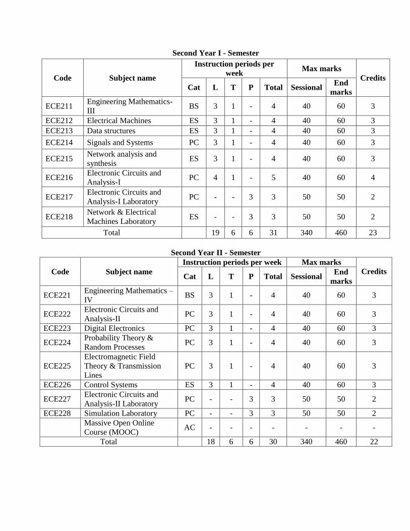
Second Year I - Semester
Code Subject name
Instruction periods per
week Max marks
Credits
Cat L T P Total Sessional End
marks
ECE211 Engineering Mathematics-
III BS 3 1 - 4 40 60 3
ECE212 Electrical Machines ES 3 1 - 4 40 60 3
ECE213 Data structures ES 3 1 - 4 40 60 3
ECE214 Signals and Systems PC 3 1 - 4 40 60 3
ECE215 Network analysis and
synthesis ES 3 1 - 4 40 60 3
ECE216 Electronic Circuits and
Analysis-I PC 4 1 - 5 40 60 4
ECE217 Electronic Circuits and
Analysis-I Laboratory PC - - 3 3 50 50 2
ECE218 Network & Electrical
Machines Laboratory ES - - 3 3 50 50 2
Total 19 6 6 31 340 460 23
Second Year II - Semester
Code Subject name
Instruction periods per week Max marks
Credits Cat L T P Total Sessional
End
marks
ECE221 Engineering Mathematics –
IV BS 3 1 - 4 40 60 3
ECE222 Electronic Circuits and
Analysis-II PC 3 1 - 4 40 60 3
ECE223 Digital Electronics PC 3 1 - 4 40 60 3
ECE224 Probability Theory &
Random Processes PC 3 1 - 4 40 60 3
ECE225
Electromagnetic Field
Theory & Transmission
Lines
PC 3 1 - 4 40 60 3
ECE226 Control Systems ES 3 1 - 4 40 60 3
ECE227 Electronic Circuits and
Analysis-II Laboratory PC - - 3 3 50 50 2
ECE228 Simulation Laboratory PC - - 3 3 50 50 2
Massive Open Online
Course (MOOC) AC - - - - - - -
Total 18 6 6 30 340 460 22
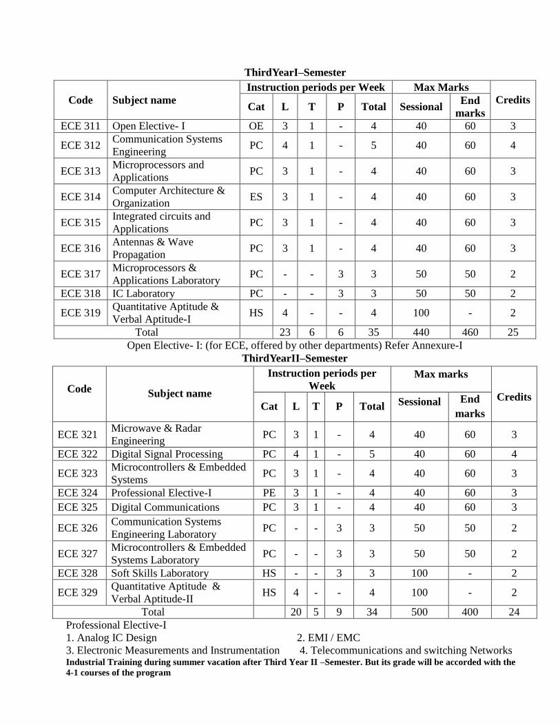
ThirdYearI–Semester
Code Subject name
Instruction periods per Week Max Marks
Credits Cat L T P Total Sessional
End
marks
ECE 311 Open Elective- I OE 3 1 - 4 40 60 3
ECE 312 Communication Systems
Engineering PC 4 1 - 5 40 60 4
ECE 313 Microprocessors and
Applications PC 3 1 - 4 40 60 3
ECE 314 Computer Architecture &
Organization ES 3 1 - 4 40 60 3
ECE 315 Integrated circuits and
Applications PC 3 1 - 4 40 60 3
ECE 316 Antennas & Wave
Propagation PC 3 1 - 4 40 60 3
ECE 317 Microprocessors &
Applications Laboratory PC - - 3 3 50 50 2
ECE 318 IC Laboratory PC - - 3 3 50 50 2
ECE 319 Quantitative Aptitude &
Verbal Aptitude-I HS 4 - - 4 100 - 2
Total 23 6 6 35 440 460 25
Open Elective- I: (for ECE, offered by other departments) Refer Annexure-I
ThirdYearII–Semester
Code Subject name
Instruction periods per
Week Max marks
Credits Cat L T P Total Sessional End
marks
ECE 321 Microwave & Radar
Engineering PC 3 1 - 4 40 60 3
ECE 322 Digital Signal Processing PC 4 1 - 5 40 60 4
ECE 323 Microcontrollers & Embedded
Systems PC 3 1 - 4 40 60 3
ECE 324 Professional Elective-I PE 3 1 - 4 40 60 3
ECE 325 Digital Communications PC 3 1 - 4 40 60 3
ECE 326 Communication Systems
Engineering Laboratory PC - - 3 3 50 50 2
ECE 327 Microcontrollers & Embedded
Systems Laboratory PC - - 3 3 50 50 2
ECE 328 Soft Skills Laboratory HS - - 3 3 100 - 2
ECE 329 Quantitative Aptitude &
Verbal Aptitude-II HS 4 - - 4 100 - 2
Total 20 5 9 34 500 400 24
Professional Elective-I
1. Analog IC Design 2. EMI / EMC
3. Electronic Measurements and Instrumentation 4. Telecommunications and switching Networks Industrial Training during summer vacation after Third Year II –Semester. But its grade will be accorded with the
4-1 courses of the program
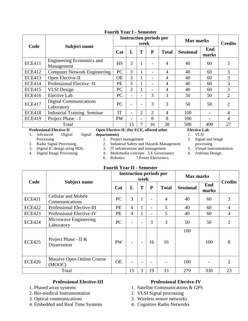
Fourth Year I - Semester
Code Subject name
Instruction periods per
week Max marks
Credits
Cat L T P Total Sessional End
marks
ECE411 Engineering Economics and
Management HS 3 1 - 4 40 60 3
ECE412 Computer Network Engineering PC 3 1 - 4 40 60 3
ECE413 Open Elective-II OE 3 1 - 4 40 60 3
ECE414 Professional Elective -II PE 3 1 - 4 40 60 3
ECE415 VLSI Design PC 3 1 - 4 40 60 3
ECE416 Elective Lab PC - - 3 3 50 50 2
ECE417 Digital Communications
Laboratory PC - - 3 3 50 50 2
ECE418 Industrial Training Seminar IT - 2 2 4 100 - 4
ECE419 Project Phase – I PW - - 8 8 100 - 4
Total 15 7 16 38 500 400 27 Professional Elective-II 1. Advanced Digital Signal
Processing
2. Radar Signal Processing
3. Digital IC design using HDL
4. Digital Image Processing
Open Elective-II: (for ECE, offered other
departments)
1. Project management
2. Industrial Safety and Hazards Management
3. IT infrastructure and management
4. Multimedia concepts 5.E-Governance
6. Robotics 7.Power Electronics
Elective Lab
1. VLSI
2. Signal and image
processing
3. Virtual instrumentation
4. Antenna Design
Fourth Year II - Semester
Code Subject name
Instruction periods per
week Max marks
Credits
Cat L T P Total Sessional End
marks
ECE421 Cellular and Mobile
Communications PC 3 1 - 4 40 60 3
ECE422 Professional Elective-III PE 4 1 - 5 40 60 4
ECE423 Professional Elective-IV PE 4 1 - 5 40 60 4
ECE424 Microwave Engineering
Laboratory PC - - 3 3 50 50 2
ECE425 Project Phase - II &
Dissertation PW - - 16 16
100
100 8
ECE426 Massive Open Online Course
(MOOC) OE - - - - 100 - 2
Total 11 3 19 33 270 330 23
Professional Elective-III Professional Elective-IV
1. Phased array systems
2. Bio-medical Instrumentation
3. Optical communications
4. Embedded and Real Time Systems
1. Satellite Communications & GPS
2. VLSI Signal processing
3. Wireless sensor networks
4. Cognitive Radio Networks
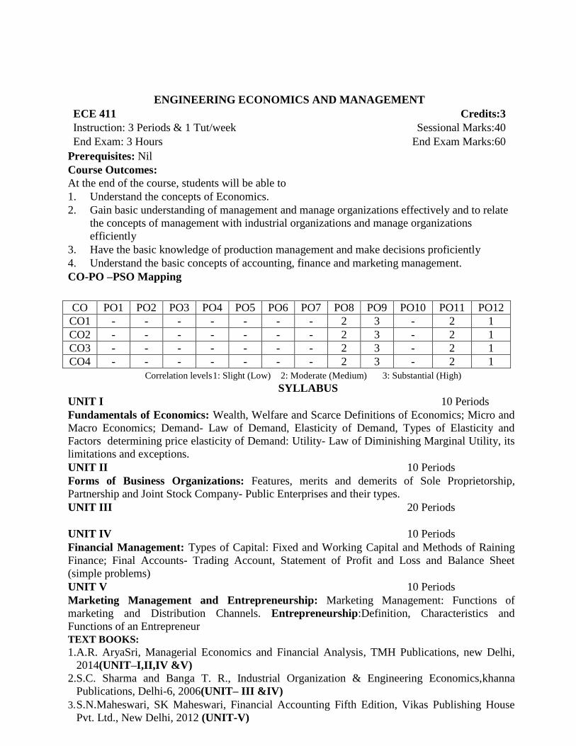
ENGINEERING ECONOMICS AND MANAGEMENT ECE 411 Credits:3
Instruction: 3 Periods & 1 Tut/week Sessional Marks:40
End Exam: 3 Hours End Exam Marks:60
Prerequisites: Nil
Course Outcomes:
At the end of the course, students will be able to
1. Understand the concepts of Economics.
2. Gain basic understanding of management and manage organizations effectively and to relate
the concepts of management with industrial organizations and manage organizations
efficiently
3. Have the basic knowledge of production management and make decisions proficiently
4. Understand the basic concepts of accounting, finance and marketing management.
CO-PO –PSO Mapping
Correlation levels 1: Slight (Low) 2: Moderate (Medium) 3: Substantial (High)
SYLLABUS
UNIT I 10 Periods
Fundamentals of Economics: Wealth, Welfare and Scarce Definitions of Economics; Micro and
Macro Economics; Demand- Law of Demand, Elasticity of Demand, Types of Elasticity and
Factors determining price elasticity of Demand: Utility- Law of Diminishing Marginal Utility, its
limitations and exceptions.
UNIT II 10 Periods
Forms of Business Organizations: Features, merits and demerits of Sole Proprietorship,
Partnership and Joint Stock Company- Public Enterprises and their types.
UNIT III 20 Periods
UNIT IV 10 Periods
Financial Management: Types of Capital: Fixed and Working Capital and Methods of Raining
Finance; Final Accounts- Trading Account, Statement of Profit and Loss and Balance Sheet
(simple problems)
UNIT V 10 Periods
Marketing Management and Entrepreneurship: Marketing Management: Functions of
marketing and Distribution Channels. Entrepreneurship:Definition, Characteristics and
Functions of an Entrepreneur
TEXT BOOKS:
1.A.R. AryaSri, Managerial Economics and Financial Analysis, TMH Publications, new Delhi,
2014(UNIT–I,II,IV &V)
2.S.C. Sharma and Banga T. R., Industrial Organization & Engineering Economics,khanna
Publications, Delhi-6, 2006(UNIT– III &IV)
3. S.N.Maheswari, SK Maheswari, Financial Accounting Fifth Edition, Vikas Publishing House
Pvt. Ltd., New Delhi, 2012 (UNIT-V)
CO PO1 PO2 PO3 PO4 PO5 PO6 PO7 PO8 PO9 PO10 PO11 PO12
CO1 - - - - - - - 2 3 - 2 1
CO2 - - - - - - - 2 3 - 2 1
CO3 - - - - - - - 2 3 - 2 1
CO4 - - - - - - - 2 3 - 2 1

COMPUTER NETWORK ENGINEERING ECE 412 Credits:3
Instruction: 3 Periods & 1 Tut/week Sessional Marks:40
End Exam: 3 Hours End Exam Marks:60
Prerequisites: Nil
Course Objectives:
To study the foundational principles, architectures, and techniques employed in computer
networks. Understand the working of Intranet, LAN, WAN, MAN setups, different topologies.
Allow the student to gain expertise in some specific areas of networking such as thedesign and
maintenance of individual networks. To be familiar with different protocols and services such as UDP, TCP and QoS To study the Internet and its protocol stack. Architecture, protocol, application-examples will
include email, web and media-streaming.
Course Outcomes:
At the end of the course, students will be able to
1. Apply the concepts of Computer Networks and Networks Models for Data Communication.
2. Analyze networking architecture and infrastructure for wired and wireless link
3. Design, calculate, and apply subnet masks and routing addresses to fulfill networking
requirements
4. Analyze issues of routing and congestion mechanism for independent and internetworking
networks for wired and wireless link.
5. Analyze internal workings of the Internet and of a number of common Internet applications
and protocols (DNS, SMTP, FTP, HTTP, WWW, Security and Cryptography).
CO-PO –PSO Mapping
CO PO PSO
1 2 3 4 5 6 7 8 9 10 11 12 1 2 3
CO1 2 2 2
CO2 2 1 2
CO3 2 3 3 2 2
CO4 1 2 2 2
CO5 2 3 3 2 2
Correlation levels 1: Slight (Low) 2: Moderate (Medium) 3: Substantial (High)
SYLLABUS
UNIT I 10 Periods
Data Communications: Components – Direction of Data flow – Networks – Components and
Categories – Types of Connections – Topologies –Protocols and Standards – ISO / OSI model –
Transmission Media – Coaxial Cable – Fiber Optics – Line Coding – Modems – RS232
Interfacing sequences
UNIT II 10 Periods
Data Link Layer: Error – detection and correction – Parity – LRC – CRC – Hamming code –
Low Control and Error control - Stop and Wait – go back-N ARQ – Selective Repeat ARQ-
Sliding window – HDLC. - LAN - Ethernet IEEE 802.3 - IEEE 802.4 - IEEE 802.5 - IEEE
802.11 – FDDI - SONET – Bridges.

UNIT III 10 Periods
Network Layer: Internetworks – Packet Switching and Datagram approach – IP addressing
methods – Subnetting – Routing – Distance Vector Routing – Link State Routing – Routers.
UNIT IV 10 Periods
Transport Layer: Duties of transport layer – Multiplexing – De-multiplexing – Sockets – User
Datagram Protocol (UDP) – Transmission Control Protocol (TCP) – Congestion Control –
Quality of services (QOS) – Integrated Services.
UNIT V 10 Periods
Application Layer:Domain Name Space (DNS) – SMTP – FTP – HTTP - WWW – Security –
Cryptography.
TEXT BOOKS:
1. William Stallings, “Data and Computer Communication”, Sixth Edition, Pearson Education,
New Delhi, 2000. [UNIT- I,II &III]
2. Andrew S. Tanenbaum, “Computer Networks”, Fourth Edition PHI Learning, New Delhi,
2003.[UNIT- IV &V]
REFERENCE BOOKS:
1. Behrouz A. Forouzan, “Data communication and Networking”, Fourth Edition, Tata
McGraw- Hill Publishing Co. Pvt., Ltd., New Delhi, 2006.
2. James F. Kurose and Keith W. Ross, “Computer Networking: A Top-Down Approach
Featuring the Internet”, Pearson Education, New Delhi, 2003.
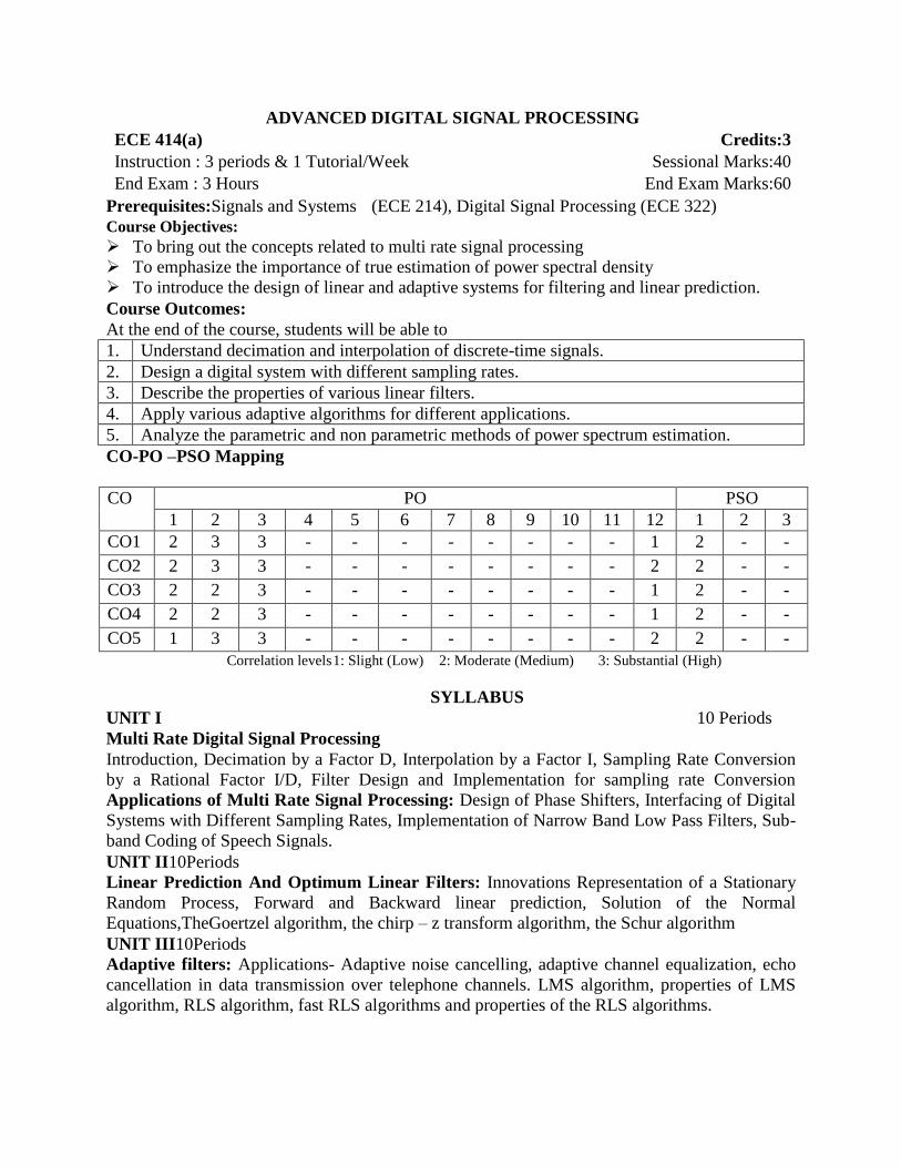
ADVANCED DIGITAL SIGNAL PROCESSING ECE 414(a) Credits:3
Instruction : 3 periods & 1 Tutorial/Week Sessional Marks:40
End Exam : 3 Hours End Exam Marks:60
Prerequisites:Signals and Systems (ECE 214), Digital Signal Processing (ECE 322)
Course Objectives:
To bring out the concepts related to multi rate signal processing
To emphasize the importance of true estimation of power spectral density
To introduce the design of linear and adaptive systems for filtering and linear prediction.
Course Outcomes:
At the end of the course, students will be able to
1. Understand decimation and interpolation of discrete-time signals.
2. Design a digital system with different sampling rates.
3. Describe the properties of various linear filters.
4. Apply various adaptive algorithms for different applications.
5. Analyze the parametric and non parametric methods of power spectrum estimation.
CO-PO –PSO Mapping
CO PO PSO
1 2 3 4 5 6 7 8 9 10 11 12 1 2 3
CO1 2 3 3 - - - - - - - - 1 2 - -
CO2 2 3 3 - - - - - - - - 2 2 - -
CO3 2 2 3 - - - - - - - - 1 2 - -
CO4 2 2 3 - - - - - - - - 1 2 - -
CO5 1 3 3 - - - - - - - - 2 2 - -
Correlation levels 1: Slight (Low) 2: Moderate (Medium) 3: Substantial (High)
SYLLABUS
UNIT I 10 Periods
Multi Rate Digital Signal Processing
Introduction, Decimation by a Factor D, Interpolation by a Factor I, Sampling Rate Conversion
by a Rational Factor I/D, Filter Design and Implementation for sampling rate Conversion
Applications of Multi Rate Signal Processing: Design of Phase Shifters, Interfacing of Digital
Systems with Different Sampling Rates, Implementation of Narrow Band Low Pass Filters, Sub-
band Coding of Speech Signals.
UNIT II10Periods
Linear Prediction And Optimum Linear Filters: Innovations Representation of a Stationary
Random Process, Forward and Backward linear prediction, Solution of the Normal
Equations,TheGoertzel algorithm, the chirp – z transform algorithm, the Schur algorithm
UNIT III10Periods
Adaptive filters: Applications- Adaptive noise cancelling, adaptive channel equalization, echo
cancellation in data transmission over telephone channels. LMS algorithm, properties of LMS
algorithm, RLS algorithm, fast RLS algorithms and properties of the RLS algorithms.

UNIT IV 10Periods
Non-Parametric Methods of Power Spectral Estimation: Estimation of spectra from finite
duration observation of signals, Non-parametric Methods: Bartlett, Welch & Blackman-Tukey
methods
UNIT V 10 Periods
Parametric Methods of Power Spectrum Estimation& DSP Processors: Autocorrelation &
Its Properties, Relation between auto correlation & model parameters, AR Models - Yule-Walker
& Burg Methods, MA & ARMA models for power spectrum estimation.
TEXT BOOKS:
1. S. M .Kay, Modern Spectral Estimation: Theory & Application, PHI, 1988.
(UNIT- I, II, III, IV, V)
2. J.G.Proakis& D. G. Manolakis, Digital Signal Processing: Principles, Algorithms
&Applications 4th Ed., PHI.
REFERENCE BOOKS:
1. Theory and applications of digital signal processing by Lawrence R. Rabiner and Bernard
Gold, PHI.
2. Digital Signal Processing, A Computer – Based approach, by Sanjit K. Mitra, Tata McGraw-
Hill, 1998
3. P.P.Vaidyanathan, Multi Rate Systems and Filter Banks , Pearson Education.
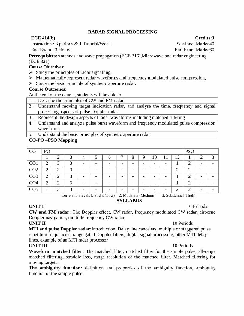
RADAR SIGNAL PROCESSING ECE 414(b) Credits:3
Instruction : 3 periods & 1 Tutorial/Week Sessional Marks:40
End Exam : 3 Hours End Exam Marks:60
Prerequisites:Antennas and wave propagation (ECE 316),Microwave and radar engineering
(ECE 321)
Course Objectives:
Study the principles of radar signalling,
Mathematically represent radar waveforms and frequency modulated pulse compression,
Study the basic principle of synthetic aperture radar.
Course Outcomes:
At the end of the course, students will be able to
1. Describe the principles of CW and FM radar
2. Understand moving target indication radar, and analyse the time, frequency and signal
processing aspects of pulse Doppler radar
3. Represent the design aspects of radar waveforms including matched filtering
4. Understand and analyze pulse burst waveform and frequency modulated pulse compression
waveforms
5. Understand the basic principles of synthetic aperture radar
CO-PO –PSO Mapping
CO PO PSO
1 2 3 4 5 6 7 8 9 10 11 12 1 2 3
CO1 2 3 3 - - - - - - - - 1 2 - -
CO2 2 3 3 - - - - - - - - 2 2 - -
CO3 2 2 3 - - - - - - - - 1 2 - -
CO4 2 2 3 - - - - - - - - 1 2 - -
CO5 1 3 3 - - - - - - - - 2 2 - -
Correlation levels 1: Slight (Low) 2: Moderate (Medium) 3: Substantial (High)
SYLLABUS
UNIT I 10 Periods
CW and FM radar: The Doppler effect, CW radar, frequency modulated CW radar, airborne
Doppler navigation, multiple frequency CW radar
UNIT II 10 Periods
MTI and pulse Doppler radar:Introduction, Delay line cancelers, multiple or staggered pulse
repetition frequencies, range gated Doppler filters, digital signal processing, other MTI delay
lines, example of an MTI radar processor
UNIT III 10 Periods
Waveform matched filter: The matched filter, matched filter for the simple pulse, all-range
matched filtering, straddle loss, range resolution of the matched filter. Matched filtering for
moving targets.
The ambiguity function: definition and properties of the ambiguity function, ambiguity
function of the simple pulse

UNIT IV 10 Periods
The pulse burst waveform: matched filtering for the pulse burst waveform, pulse-by-pulse
processing, range ambiguity, Doppler response for the pulse burst waveform, the slow-time
spectrum and the periodic ambiguity function
Frequency modulated pulse compression waveforms: linear frequency modulation, the
principle of stationary pulse, ambiguity function of the LFM waveform, range-Doppler coupling,
stretch processing
UNIT V 10 Periods
Synthetic Aperture Radar:Basic block diagram of a typical SAR radar, introduction, constraint
and resolution swath, radar equation for SAR, equipment consideration, optinal processing,
digital processing, Doppler-frequency model, range resolution, other aspects of SAR,
introduction to inverse SAR
TEXT BOOKS:
1. Merill I. Skolnik, “Introduction to radar systems,” Tata McGraw-Hill, 2007
(UNITS- I,II &V)
2. Mark A. Richards, “Fundementals of radar signal processing,” Tata Mc-Graw-Hill
Educations, 2005 (UNITS- III &IV)
REFERENCE BOOKS:
1. Canner Ozedemir, “Inverse synthetic aperture radar imaging with MATLAB algorithms,”
Vol 210., John Wiley & Sons, 2012
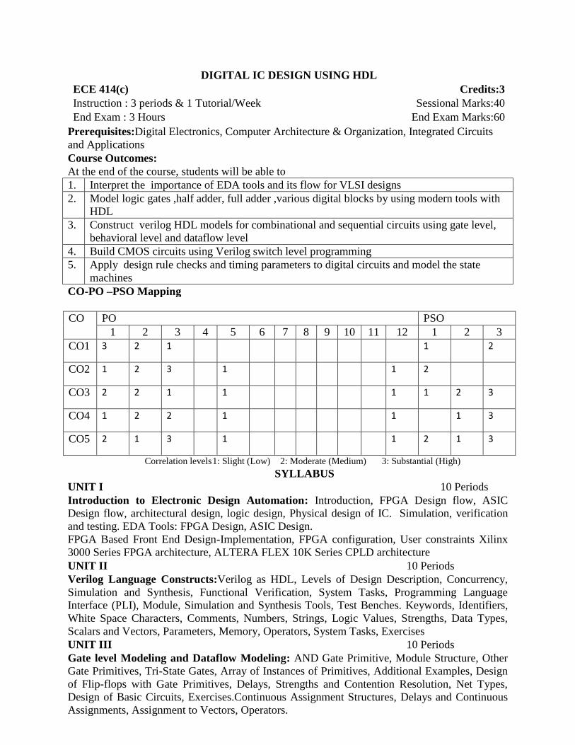
DIGITAL IC DESIGN USING HDL ECE 414(c) Credits:3
Instruction : 3 periods & 1 Tutorial/Week Sessional Marks:40
End Exam : 3 Hours End Exam Marks:60
Prerequisites:Digital Electronics, Computer Architecture & Organization, Integrated Circuits
and Applications
Course Outcomes:
At the end of the course, students will be able to
1. Interpret the importance of EDA tools and its flow for VLSI designs
2. Model logic gates ,half adder, full adder ,various digital blocks by using modern tools with
HDL
3. Construct verilog HDL models for combinational and sequential circuits using gate level,
behavioral level and dataflow level
4. Build CMOS circuits using Verilog switch level programming
5. Apply design rule checks and timing parameters to digital circuits and model the state
machines
CO-PO –PSO Mapping
CO PO PSO
1 2 3 4 5 6 7 8 9 10 11 12 1 2 3
CO1 3 2 1 1 2
CO2 1 2 3 1 1 2
CO3 2 2 1 1 1 1 2 3
CO4 1 2 2 1 1 1 3
CO5 2 1 3 1 1 2 1 3
Correlation levels 1: Slight (Low) 2: Moderate (Medium) 3: Substantial (High)
SYLLABUS
UNIT I 10 Periods
Introduction to Electronic Design Automation: Introduction, FPGA Design flow, ASIC
Design flow, architectural design, logic design, Physical design of IC. Simulation, verification
and testing. EDA Tools: FPGA Design, ASIC Design.
FPGA Based Front End Design-Implementation, FPGA configuration, User constraints Xilinx
3000 Series FPGA architecture, ALTERA FLEX 10K Series CPLD architecture
UNIT II 10 Periods
Verilog Language Constructs:Verilog as HDL, Levels of Design Description, Concurrency,
Simulation and Synthesis, Functional Verification, System Tasks, Programming Language
Interface (PLI), Module, Simulation and Synthesis Tools, Test Benches. Keywords, Identifiers,
White Space Characters, Comments, Numbers, Strings, Logic Values, Strengths, Data Types,
Scalars and Vectors, Parameters, Memory, Operators, System Tasks, Exercises
UNIT III 10 Periods
Gate level Modeling and Dataflow Modeling: AND Gate Primitive, Module Structure, Other
Gate Primitives, Tri-State Gates, Array of Instances of Primitives, Additional Examples, Design
of Flip-flops with Gate Primitives, Delays, Strengths and Contention Resolution, Net Types,
Design of Basic Circuits, Exercises.Continuous Assignment Structures, Delays and Continuous
Assignments, Assignment to Vectors, Operators.

UNIT IV 10 Periods
Behavioraland Switch Level Modeling: Introduction, Operations and Assignments,
Functional Bifurcation, Initial Construct, Always Construct, Examples, Assignments with
Delays, Wait construct, Multiple Always Blocks, Designs at Behavioral Level, Blocking and
Non blocking Assignments, The case statement, Simulation Flow. iƒand iƒ-else constructs,
repeat construct, for loop, , while loop, forever loop, parallel blocks, force-release construct,
Event. Basic Transistor Switches, CMOS Switch, Bi-directional Gates, Time Delays with Switch
Primitives, Instantiations with Strengths and Delays, Strength Contention with Trireg Nets,
Exercises
UNIT V 10 Periods
System Tasks, Functions, UDP and SM Charts:Introduction, Parameters, Path Delays,
Module Parameters, System Tasks and Functions. File Based Tasks and Functions, Compiler
Directives, Hierarchical Access, General observations, Exercises.
User-Defined Functions, Tasks and Primitives-Introduction, Function, Tasks, User- Defined
Primitives (UDP), FSM Design (Moore and Mealy Machines), State Machine Charts, Derivation
of SM Charts, Realization of SM Charts, Examples based on SM charts
TEXT BOOKS:
1. T.R. Padmanabhan and B. Bala Tripura Sundari,” Design through Verilog HDL” WSE,
IEEE Press, 2004(UNIT-I,II,III,IV &V)
2. J. Bhaskar” A Verilog Primier” ,First edition ,BSP, 2003(UNIT-I,II,III,IV &V)
REFERENCE BOOKS:
1. Brown and ZvonkoVranesic Stephen” Fundamentals of Logic Design with Verilog ”TMH,
2005.
2. Michael D. Ciletti “Advanced Digital Design with Verilog HDL “,Second edition, PHI,
2005.

DIGITAL IMAGE PROCESSING ECE 414(d) Credits:3
Instruction : 3 periods & 1 Tutorial/Week Sessional Marks:40
End Exam : 3 Hours End Exam Marks:60
Prerequisites:Signal & System (ECE 214), Digital Signal Processing (ECE 322)
Course Outcomes:
By the end of the course, students will be able to
1. Describe the basic components of digital image processing system and transform techniques
(FFT, DCT and Hadamard transform).
2. Analyze image enhancement in spatial domain using smoothing and sharpening operators.
3. Analyze image enhancement in frequency domain using High pass and low pass filters.
4. Describe image restoration using Weiner filtering and image segmentation using
thresholding and region growing techniques.
5. Compare and contrast image compression techniques (Variable length coding, LZW coding, Bit
plane coding, Lossless predictive coding, Lossy prediction, transform coding).
CO-PO –PSO Mapping
CO PO PSO
1 2 3 4 5 6 7 8 9 10 11 12 1 2 3
CO1 2 3 3 - - - - - - - - 1 3 - -
CO2 2 3 3 - - - - - - - - 2 3 - -
CO3 2 3 3 - - - - - - - - 2 3 - -
CO4 2 2 3 - - - - - - - - 1 3 - -
CO5 2 2 3 - - - - - - - - 1 3 - -
Correlation levels 1: Slight (Low) 2: Moderate (Medium) 3: Substantial (High)
SYLLABUS
UNIT I 10 Periods
Digital Image Fundamentals: Fundamental steps in digital image processing, Components of
an image processing system, Elements of visual perception, Image sensing and acquisition,
Image sampling and quantization, Basic relationship between pixels
Image Transforms: Two-dimensional FFT properties, Discrete cosine transform &Hardmard
transform
UNIT II 10 Periods
Image Enhancement (Spatial Domain): Introduction, Basic gray level transformation,
Histogram processing, Enhancement using arithmetic/logic operations, Basics of spatial filtering:
Smoothing and sharpening spatial filter
UNIT III 10 Periods
Image Enhancement (Frequency Domain): Introduction to Fourier transform and the
frequency domain, Smoothing and sharpening frequency domain filters, Homomorphic filtering
UNIT IV 10 Periods
Image Restoration: Introductionto image degradation, Noise model, Restoration in presence of
noise only, Inverse filtering, Wiener filtering,
Image Segmentation: Detection of discontinuities, Edge linking and boundary detection,
Thresholding (global and adaptive), Region based segmentation
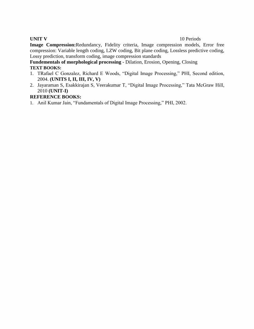
UNIT V 10 Periods
Image Compression:Redundancy, Fidelity criteria, Image compression models, Error free
compression: Variable length coding, LZW coding, Bit plane coding, Lossless predictive coding,
Lossy prediction, transform coding, image compression standards
Fundementals of morphological processing - Dilation, Erosion, Opening, Closing
TEXT BOOKS:
1. TRafael C Gonzalez, Richard E Woods, “Digital Image Processing,” PHI, Second edition,
2004. (UNITS I, II, III, IV, V)
2. Jayaraman S, Esakkirajan S, Veerakumar T, “Digital Image Processing,” Tata McGraw Hill,
2010 (UNIT-I)
REFERENCE BOOKS:
1. Anil Kumar Jain, “Fundamentals of Digital Image Processing,” PHI, 2002.

VLSI DESIGN ECE 415 Credits:3
Instruction : 3 periods & 1 Tutorial/Week Sessional Marks:40
End Exam : 3 Hours End Exam Marks:60
Prerequisites:DigitalElectronics, ECA-I, ECA-II, IC analysis
Course Outcomes:
By the end of the course, students will be able to
1. Delineate IC Production process, fabrication processes for NMOS, PMOS, BiCMOS
Technologies.
2. Analyze CMOS electrical properties with circuit concepts.
3. Draw stick diagrams, layouts for CMOS circuits and compute delays of CMOS circuits
using modern tools.
4. Design and test the CMOS digital Circuits at different levels of abstraction using modern
tools.
5. Apply testing methods on the digital designs for DFT.
CO-PO –PSO Mapping
CO PO PSO
1 2 3 4 5 6 7 8 9 10 11 12 1 2 3
CO1 3 0 0 0 0 0 0 0 0 0 0 0 2 1 2
CO2 3 2 1 0 1 0 0 0 0 0 0 0 2 2 1
CO3 3 3 3 0 1 0 0 0 0 0 0 0 2 1 1
CO4 3 2 3 0 0 0 0 0 0 0 0 1 2 2 1
CO5 3 2 2 0 0 0 1 0 0 0 1 1 2 1 2 Correlation levels 1: Slight (Low) 2: Moderate (Medium) 3: Substantial (High)
SYLLABUS
UNIT I 10 Periods
IC Technology: MOS, PMOS, NMOS, CMOS &BiCMOS technologies- Oxidation,
Lithography, Diffusion, Ion implantation, Metallization, Encapsulation, Integrated Resistors and
Capacitors.
UNIT II 10 Periods
CMOS Electrical Properties:Basic Electrical Properties of MOS and BiCMOS Circuits: Ids-
Vds relationships, MOS transistor threshold Voltage, gm, gds, figure of merit, Pass transistor,
NMOS Inverter, Various pull ups, CMOS Inverter analysis and design, Bi-CMOS Inverters.
Basic circuit concepts:
Sheet Resistance RS and its concept to MOS, Area Capacitance Units, Calculations - Delays,
driving large Capacitive Loads, Wiring Capacitances, Fan-in and fan-out, Choice of layers
UNIT III 10 Periods
VLSI Design Flow, MOS Layers, Stick Diagrams, Design Rules and Layout, 2 micron CMOS
Design rules, Contacts and Transistors Layout Diagrams for NMOS and CMOS Inverters and
Gates, Scaling of MOS circuits, Limitations of Scaling.
UNIT IV 10 Periods
Gate Level Design: Logic Gates and Other complex gates, Switch logic, Alternate gate circuits.
Different CMOS logic Circuits-Pseudo, Dynamic, Domino, C2MOS.
Subsystem Design: Subsystem Design, Shifters, Adders, ALUs, Multipliers, Parity generators,
Comparators.

UNIT V 10 Periods
VLSI Testing:CMOS Testing, Need for testing, Test Principles, Design Strategies for test, Chip
level Test Techniques, System-level Test Techniques, Design for testability, Practical design for
test guidelines, Buil-In-Self-Test
TEXT BOOKS:
1. Douglas A, Pucknell, Kamran Eshraghian,“Basic VLSI Design”,3rd Edition,Prentice Hall,
l996.(UNITS I, II, III, IV & V)
2. Weste and Eshraghian, “Principles of CMOS VLSI Design”, Pearson Education, 1999
REFERENCE BOOKS:
1. John .P. Uyemura,“Introduction to VLSI Circuits and Systems”,JohnWiley, 2003.
2. Wayne Wolf, “Modern VLSI Design”, 3rd Edition, Pearson Education, 1997

VLSI LAB ECE 416(a) Credits:2
Instruction: 3 Practical‟s /Week Sessional Marks:50
End Exam: 3 Hours End Exam Marks:50
Prerequisites:Digital Electronics, VHDL, Verilog
Course Outcomes:
At the end of the course, students will be able to
1. Work with XILINX VLSI design tools.
2. Develop the systems for various signal processing and computing applications
3. Test and verify the prototypes at system level using XILINX Vivado simulators.
4. Analyze and Develop the prototypes of Digital systems on Artix 7 FPGA.
CO-PO –PSO Mapping
CO PO PSO
1 2 3 4 5 6 7 8 9 10 11 12 1 2 3
CO1 2 1 2 2 3 - - - - - 1 2 2 2
CO2 3 2 2 2 3 - - - - - 1 2 3 2
CO3 3 2 2 2 3 - - - - - 1 2 2 2
CO4 3 2 3 3 3 - - - - - 1 3 3 3 Correlation levels 1: Slight (Low) 2: Moderate (Medium) 3: Substantial (High)
SYLLABUS
CYCLE IDigital Design using HDL
Experiment 1: Static Display
Experiment 2: Frequency Divider
Experiment 3: Traffic Light Controller
Experiment 4: Design of Memories
CYCLE IIFPGA prototyping using Artix 7
Experiment 1: Familiarization with Artix 7 FPGA
Experiment 2: Implementation of Adders on Artix 7 FPGA using Verilog
Experiment 3: Implementation of Multipliers on Artix 7 FPGA using Verilog
Experiment 4: Implementation of Moore and Mealy FSM on Artix 7 FPGA using Verilog
Experiment 5: Implementation of ALU on Artix 7 FPGA
Experiment 6: Implementation of 8 bit MAC on Artix 7 FPGA
TEXT BOOKS:
1. JayaramBhasker, “A Verilog Primer”, AT&T, Prentice Hall
2. Samir Palnitkar, “Verilog HDL: A Guide to Digital Design And Synthesis”, SunSoft
Press1996
REFERENCE BOOKS:
1. ZainalabedinNavabi, “Verilog Digital System Design”, 2nd
Edition, McGraw-Hill, 2006
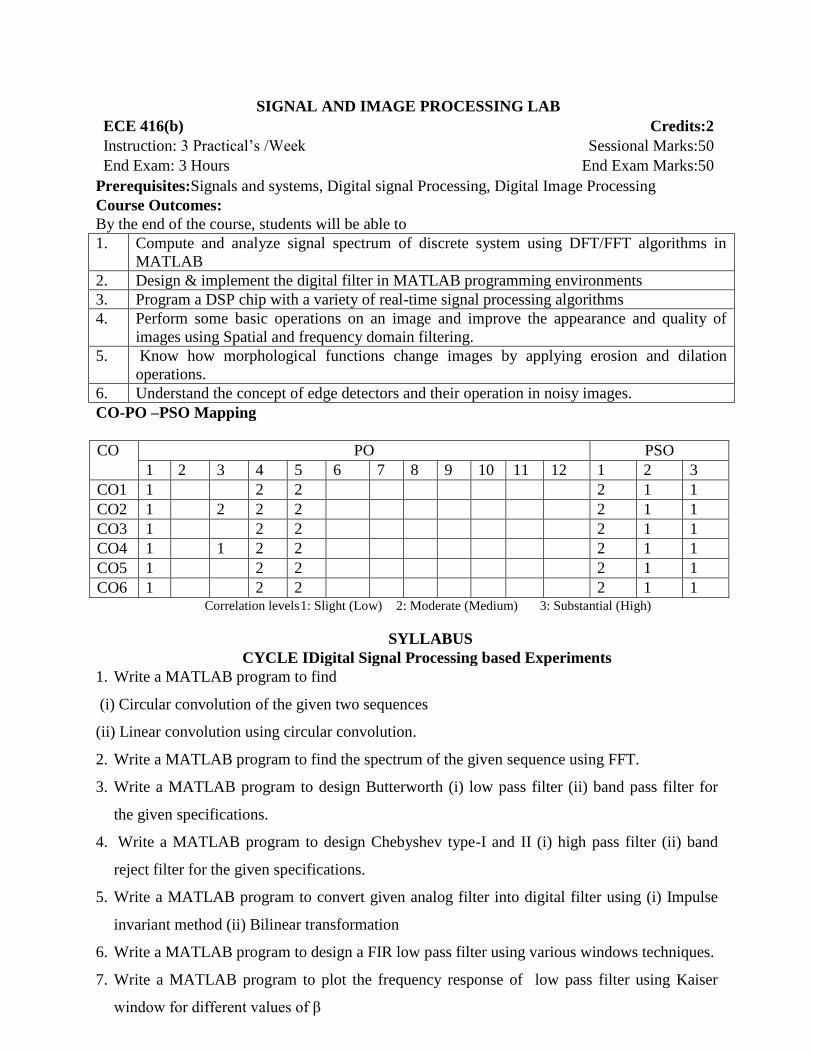
SIGNAL AND IMAGE PROCESSING LAB ECE 416(b) Credits:2
Instruction: 3 Practical‟s /Week Sessional Marks:50
End Exam: 3 Hours End Exam Marks:50
Prerequisites:Signals and systems, Digital signal Processing, Digital Image Processing
Course Outcomes:
By the end of the course, students will be able to
1. Compute and analyze signal spectrum of discrete system using DFT/FFT algorithms in
MATLAB
2. Design & implement the digital filter in MATLAB programming environments
3. Program a DSP chip with a variety of real-time signal processing algorithms
4. Perform some basic operations on an image and improve the appearance and quality of
images using Spatial and frequency domain filtering.
5. Know how morphological functions change images by applying erosion and dilation
operations.
6. Understand the concept of edge detectors and their operation in noisy images.
CO-PO –PSO Mapping
CO PO PSO
1 2 3 4 5 6 7 8 9 10 11 12 1 2 3
CO1 1 2 2 2 1 1
CO2 1 2 2 2 2 1 1
CO3 1 2 2 2 1 1
CO4 1 1 2 2 2 1 1
CO5 1 2 2 2 1 1
CO6 1 2 2 2 1 1 Correlation levels 1: Slight (Low) 2: Moderate (Medium) 3: Substantial (High)
SYLLABUS
CYCLE IDigital Signal Processing based Experiments
1. Write a MATLAB program to find
(i) Circular convolution of the given two sequences
(ii) Linear convolution using circular convolution.
2. Write a MATLAB program to find the spectrum of the given sequence using FFT.
3. Write a MATLAB program to design Butterworth (i) low pass filter (ii) band pass filter for
the given specifications.
4. Write a MATLAB program to design Chebyshev type-I and II (i) high pass filter (ii) band
reject filter for the given specifications.
5. Write a MATLAB program to convert given analog filter into digital filter using (i) Impulse
invariant method (ii) Bilinear transformation
6. Write a MATLAB program to design a FIR low pass filter using various windows techniques.
7. Write a MATLAB program to plot the frequency response of low pass filter using Kaiser
window for different values of β
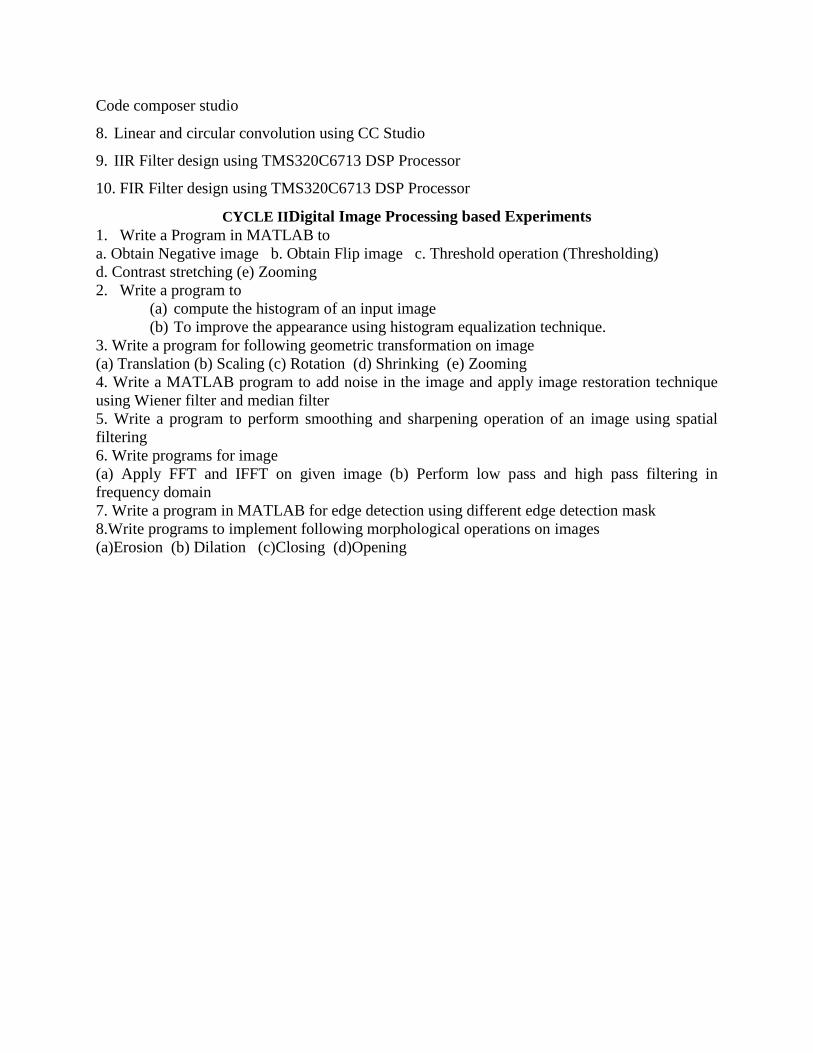
Code composer studio
8. Linear and circular convolution using CC Studio
9. IIR Filter design using TMS320C6713 DSP Processor
10. FIR Filter design using TMS320C6713 DSP Processor
CYCLE IIDigital Image Processing based Experiments
1. Write a Program in MATLAB to
a. Obtain Negative image b. Obtain Flip image c. Threshold operation (Thresholding)
d. Contrast stretching (e) Zooming
2. Write a program to
(a) compute the histogram of an input image
(b) To improve the appearance using histogram equalization technique.
3. Write a program for following geometric transformation on image
(a) Translation (b) Scaling (c) Rotation (d) Shrinking (e) Zooming
4. Write a MATLAB program to add noise in the image and apply image restoration technique
using Wiener filter and median filter
5. Write a program to perform smoothing and sharpening operation of an image using spatial
filtering
6. Write programs for image
(a) Apply FFT and IFFT on given image (b) Perform low pass and high pass filtering in
frequency domain
7. Write a program in MATLAB for edge detection using different edge detection mask
8.Write programs to implement following morphological operations on images
(a)Erosion (b) Dilation (c)Closing (d)Opening

VIRTUAL INSTRUMENTATION LAB ECE 416(c) Credits:2
Instruction: 3 Practical‟s /Week Sessional Marks:50
End Exam: 3 Hours End Exam Marks:50
Prerequisites:Nil
Course Outcomes:
By the end of the course, students will be able to
1. Develop software programs called virtual instruments that apply user interface, program
control, data structures, file input output, hardware interfacing, data analysis and signal
processing
2. Experiment with,analyze and document prototype measurement systems using a computer,
plug in DAQ interfaces and bench level instruments.
3. Build an engineering application in lab view, install and configure data acquisition
hardware.
4. Design DAQ using LABVIEW modules.
CO-PO –PSO Mapping
CO PO PSO
1 2 3 4 5 6 7 8 9 10 11 12 1 2 3
CO1 3 2
1
3 2 1 1
CO2 2
1
3
1 2 1
3 2 1 1
CO3 2 2 2
1
2
3 3 2 1 1
CO4 2 1 1
3
1 2 3 2 1 1 Correlation levels 1: Slight (Low) 2: Moderate (Medium) 3: Substantial (High)
SYLLABUS
List of Experiments
Experiment 1:
Introduction To Labview
Installing labview software and other toolkits
Experiment 2:
1. Basic arithmetic operations
2. Boolean operations
3. Sum of „n‟ numbers using „for‟ loop
Experiment 3:
4. Factorial Of A Give Number Using For Loop
5. Sum Of „N‟ Natural Numbers Using While Loop
6. Factorial Of A Give Number Using While Loop
Experiment 4:
7. Sorting even numbers using while loop in an array
8. Array maximum and minimum
Experiment 5:
9. Bundle And Unbundle Cluster
10. Flat And Stacked Sequence
11. Application Using Formula Node
Experiment 6:
12. Median Filter
13. Discrete Cosine Transform
Experiment 7:

14. Convolution Of Two Signals
15. Filter Design Using Windowing Technique
Experiment 8:
16.File Transfer Using Sockets
Experiment 9:
17. Acquiring And Processing Speech Signal
18. Acquiring And Processing Image Signal
Experiment 10:
19. Talking Tom Application
20. Developing A Scientific Calculator
Experiment 11:
21.Digital Modulation Like Psk, Qam
22.Estimation, Ber And Eye Diagram
Experiment 12:
23.Design Of Various Filters Like Wave Shaping, Matched, Equalizer

ANTENNA DESIGN LAB ECE 416(d) Credits:2
Instruction: 3 Practical‟s /Week Sessional Marks:50
End Exam: 3 Hours End Exam Marks:50
Prerequisites:Nil
Course Outcomes:
At the end of the course, students will be able to
1. Get familiarized with the simulation software
2. Design the antenna with given specification using the simulation tools.
3. Extract the various parameters that indicate the performance of the antenna
4. Interpret the extracted results and analyse them and prepare a formal laboratory report.
CO-PO –PSO Mapping
CO PO PSO
1 2 3 4 5 6 7 8 9 10 11 12 1 2 3
CO1 - 1 2 1 - - - - 2 - - 1 2 2
CO2 - 2 1 3 - - - - 2 - - 2 2 2 2
CO3 - 2 2 1 - - - - 2 3 - 1 1 1 1
CO4 - 3 3 3 - - - - 2 - 3 1 2 2
Correlation levels 1: Slight (Low) 2: Moderate (Medium) 3: Substantial (High)
SYLLABUS
List of Experiments
1. Design an edge fed microstrip patch antenna & study its S-parameters
2. Design an inset fed microstrip patch antenna & study its S-parameters
3. Design an microstrip line fed slot coupled patch antenna & study its S- Parameters
4. Design a probe fed microstrip patch antenna & study its S- Parameters
5. Design a coplanar waveguide fed patch antenna & study its S- Parameters
6. Design an edge fed microstrip patch antenna & study its 2-D & 3-D radiation Patterns
7. Design an inset fed microstrip patch antenna & study its 2-D & 3-D radiation Patterns
8. Design an microstrip line fed slot coupled patch antenna & study its 2-D & 3-D radiation
Patterns
9. Design a probe fed microstrip patch antenna & study its 2-D & 3-D radiation Patterns
10. Design a coplanar waveguide fed patch antenna & study its 2-D & 3-D radiation Patterns
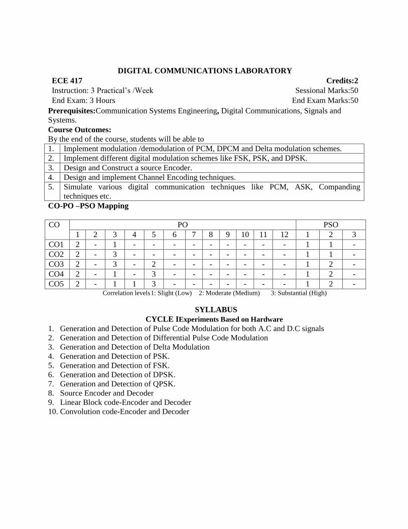
DIGITAL COMMUNICATIONS LABORATORY ECE 417 Credits:2
Instruction: 3 Practical‟s /Week Sessional Marks:50
End Exam: 3 Hours End Exam Marks:50
Prerequisites:Communication Systems Engineering, Digital Communications, Signals and
Systems.
Course Outcomes:
By the end of the course, students will be able to
1. Implement modulation /demodulation of PCM, DPCM and Delta modulation schemes.
2. Implement different digital modulation schemes like FSK, PSK, and DPSK.
3. Design and Construct a source Encoder.
4. Design and implement Channel Encoding techniques.
5. Simulate various digital communication techniques like PCM, ASK, Companding
techniques etc.
CO-PO –PSO Mapping
CO PO PSO
1 2 3 4 5 6 7 8 9 10 11 12 1 2 3
CO1 2 - 1 - - - - - - - - - 1 1 -
CO2 2 - 3 - - - - - - - - - 1 1 -
CO3 2 - 3 - 2 - - - - - - - 1 2 -
CO4 2 - 1 - 3 - - - - - - - 1 2 -
CO5 2 - 1 1 3 - - - - - - - 1 2 - Correlation levels 1: Slight (Low) 2: Moderate (Medium) 3: Substantial (High)
SYLLABUS
CYCLE IExperiments Based on Hardware
1. Generation and Detection of Pulse Code Modulation for both A.C and D.C signals
2. Generation and Detection of Differential Pulse Code Modulation
3. Generation and Detection of Delta Modulation
4. Generation and Detection of PSK.
5. Generation and Detection of FSK.
6. Generation and Detection of DPSK.
7. Generation and Detection of QPSK.
8. Source Encoder and Decoder
9. Linear Block code-Encoder and Decoder
10. Convolution code-Encoder and Decoder

CYCLE IIExperiments Based on Software
1. Simulation of Pulse Code Modulation
2. Simulation of Differential Pulse Code Modulation
3. Simulation of Amplitude Shift Keying
4. Simulation of Phase Shift keying
5. Companding
6. Simulation of Time Division Multiplexing
Note:A student has to perform minimum of 10 experiments.
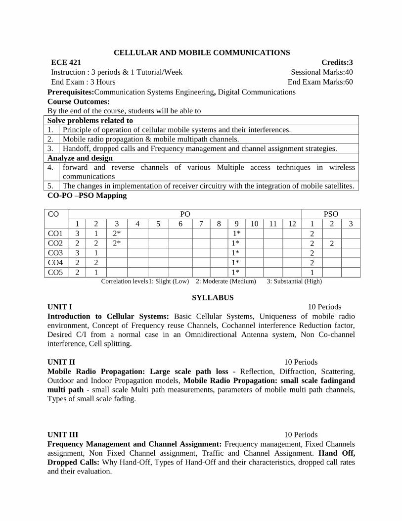
CELLULAR AND MOBILE COMMUNICATIONS ECE 421 Credits:3
Instruction : 3 periods & 1 Tutorial/Week Sessional Marks:40
End Exam : 3 Hours End Exam Marks:60
Prerequisites:Communication Systems Engineering, Digital Communications
Course Outcomes:
By the end of the course, students will be able to
Solve problems related to
1. Principle of operation of cellular mobile systems and their interferences.
2. Mobile radio propagation & mobile multipath channels.
3. Handoff, dropped calls and Frequency management and channel assignment strategies.
Analyze and design
4. forward and reverse channels of various Multiple access techniques in wireless
communications
5. The changes in implementation of receiver circuitry with the integration of mobile satellites.
CO-PO –PSO Mapping
CO PO PSO
1 2 3 4 5 6 7 8 9 10 11 12 1 2 3
CO1 3 1 2* 1* 2
CO2 2 2 2* 1* 2 2
CO3 3 1 1* 2
CO4 2 2 1* 2
CO5 2 1 1* 1
Correlation levels 1: Slight (Low) 2: Moderate (Medium) 3: Substantial (High)
SYLLABUS
UNIT I 10 Periods
Introduction to Cellular Systems: Basic Cellular Systems, Uniqueness of mobile radio
environment, Concept of Frequency reuse Channels, Cochannel interference Reduction factor,
Desired C/I from a normal case in an Omnidirectional Antenna system, Non Co-channel
interference, Cell splitting.
UNIT II 10 Periods
Mobile Radio Propagation: Large scale path loss - Reflection, Diffraction, Scattering,
Outdoor and Indoor Propagation models, Mobile Radio Propagation: small scale fadingand
multi path - small scale Multi path measurements, parameters of mobile multi path channels,
Types of small scale fading.
UNIT III 10 Periods
Frequency Management and Channel Assignment: Frequency management, Fixed Channels
assignment, Non Fixed Channel assignment, Traffic and Channel Assignment. Hand Off,
Dropped Calls: Why Hand-Off, Types of Hand-Off and their characteristics, dropped call rates
and their evaluation.
UNIT IV 10 Periods
Multiple access techniques for wireless communications: FDMA, TDMA, Spread spectrum
techniques, SDMA, Packet Radio, CSMA , Capacity of cellular CDMA with multiple cells and
capacity of SDMA, Details of forward and reverse CDMA channels
UNIT V 10 Periods
Personal access communication systems, personal Mobile satellite communications, Integrating
GEO, LEO, MEO satellite and terrestrial mobile systems, Rake receiver and Advanced Rake
receiver.
*Note- Additional topics that can be introduced during the course but are out of the prescribed
syllabus – Performance of Fading channels
TEXT BOOKS:
1. William C.Y.Lee, Wireless & Cellular Telecommunications, Third Edition,McGraw Hill,
International Edition. [UNIT- I ,II,III]
2. Theodore S.Rappaport, Wireless communications Principles and Practice, Second Editions,
Pearson Publications. [UNIT- IV ,V]
REFERENCE BOOKS:
1. GottapuSasibhushanaRao, Mobile Cellular Communication, PEARSON International,
2012.
2. Wayne Tomasi, Electronic Communication system, Pearson.
PHASED ARRAY SYSTEMS ECE 422(a) Credits:4
Instruction : 4 periods & 1 Tutorial/Week Sessional Marks:40
End Exam : 3 Hours End Exam Marks:60
Prerequisites:Antenna and Wave Propagation
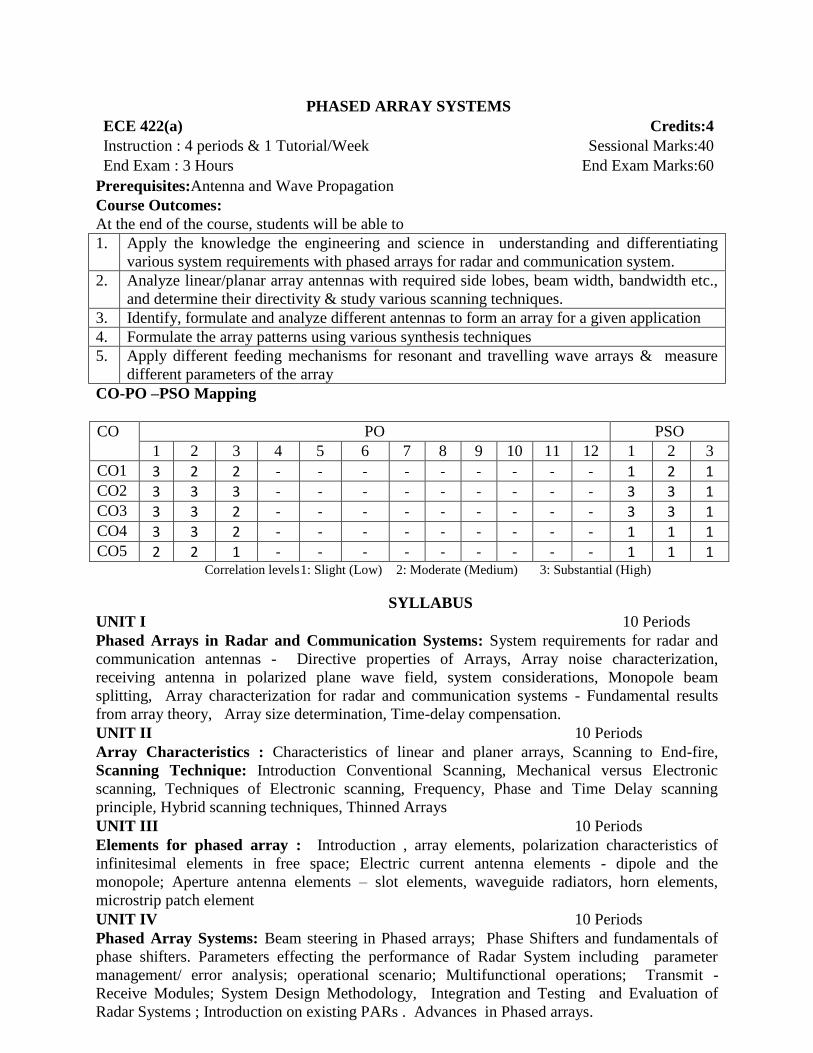
Course Outcomes:
At the end of the course, students will be able to
1. Apply the knowledge the engineering and science in understanding and differentiating
various system requirements with phased arrays for radar and communication system.
2. Analyze linear/planar array antennas with required side lobes, beam width, bandwidth etc.,
and determine their directivity & study various scanning techniques.
3. Identify, formulate and analyze different antennas to form an array for a given application
4. Formulate the array patterns using various synthesis techniques
5. Apply different feeding mechanisms for resonant and travelling wave arrays & measure
different parameters of the array
CO-PO –PSO Mapping
CO PO PSO
1 2 3 4 5 6 7 8 9 10 11 12 1 2 3
CO1 3 2 2 - - - - - - - - - 1 2 1 CO2 3 3 3 - - - - - - - - - 3 3 1 CO3 3 3 2 - - - - - - - - - 3 3 1 CO4 3 3 2 - - - - - - - - - 1 1 1 CO5 2 2 1 - - - - - - - - - 1 1 1
Correlation levels 1: Slight (Low) 2: Moderate (Medium) 3: Substantial (High)
SYLLABUS
UNIT I 10 Periods
Phased Arrays in Radar and Communication Systems: System requirements for radar and
communication antennas - Directive properties of Arrays, Array noise characterization,
receiving antenna in polarized plane wave field, system considerations, Monopole beam
splitting, Array characterization for radar and communication systems - Fundamental results
from array theory, Array size determination, Time-delay compensation.
UNIT II 10 Periods
Array Characteristics : Characteristics of linear and planer arrays, Scanning to End-fire,
Scanning Technique: Introduction Conventional Scanning, Mechanical versus Electronic
scanning, Techniques of Electronic scanning, Frequency, Phase and Time Delay scanning
principle, Hybrid scanning techniques, Thinned Arrays
UNIT III 10 Periods
Elements for phased array : Introduction , array elements, polarization characteristics of
infinitesimal elements in free space; Electric current antenna elements - dipole and the
monopole; Aperture antenna elements – slot elements, waveguide radiators, horn elements,
microstrip patch element
UNIT IV 10 Periods
Phased Array Systems: Beam steering in Phased arrays; Phase Shifters and fundamentals of
phase shifters. Parameters effecting the performance of Radar System including parameter
management/ error analysis; operational scenario; Multifunctional operations; Transmit -
Receive Modules; System Design Methodology, Integration and Testing and Evaluation of
Radar Systems ; Introduction on existing PARs . Advances in Phased arrays.
UNIT V 10 Periods
Array Feeds & Measurements: Introduction, Series feeds: Resonant Arrays- Impedance and
bandwidth, Resonant slot array Travelling Wave Arrays- Frequency Squint and Single Beam
condition, Calculation of element conductance, TW slot array Frequency scanning, Phase
scanning; Shunt feeds: Corporate feeds, distributed feeds, Introduction - measurement of Low
sidelobe patterns & scanning phenomena.
TEXT BOOKS:
1. Robert J. Mailloux, Phased Array Antenna Handbook, Third Edition, Artech House, 2017
[UNIT- I ,II &III] 2. R.C.Hansen, Phased Array Antennas, Second edition, John Wiley & Sons Publications
2009 [UNIT - IV]
REFERENCE BOOKS:
1. Peter J. Kahrilas, Electronics Scanning Radar Systems Desing Handbook, Artech House,
1976.
2. A. A. Olinar, G. H. Knittel, Phased Array Radar, Artech House, 1972
3. Skolnik, M.I., Radar Handbook, 3rd edn., The McGraw-Hill Companies, 2008
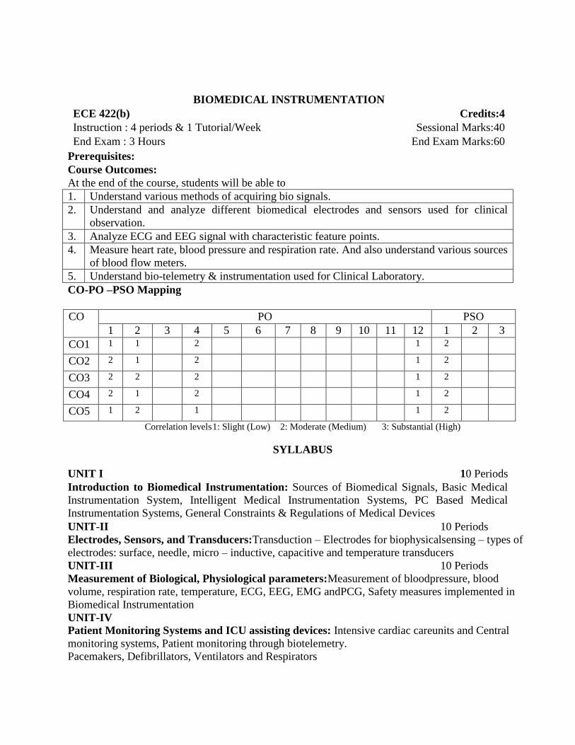
BIOMEDICAL INSTRUMENTATION ECE 422(b) Credits:4
Instruction : 4 periods & 1 Tutorial/Week Sessional Marks:40
End Exam : 3 Hours End Exam Marks:60
Prerequisites:
Course Outcomes:
At the end of the course, students will be able to
1. Understand various methods of acquiring bio signals.
2. Understand and analyze different biomedical electrodes and sensors used for clinical
observation.
3. Analyze ECG and EEG signal with characteristic feature points.
4. Measure heart rate, blood pressure and respiration rate. And also understand various sources
of blood flow meters.
5. Understand bio-telemetry & instrumentation used for Clinical Laboratory.
CO-PO –PSO Mapping
CO PO PSO
1 2 3 4 5 6 7 8 9 10 11 12 1 2 3
CO1 1 1
2
1 2
CO2 2 1
2
1 2
CO3 2 2
2
1 2
CO4 2 1
2
1 2
CO5 1 2
1
1 2
Correlation levels 1: Slight (Low) 2: Moderate (Medium) 3: Substantial (High)
SYLLABUS
UNIT I 10 Periods
Introduction to Biomedical Instrumentation: Sources of Biomedical Signals, Basic Medical
Instrumentation System, Intelligent Medical Instrumentation Systems, PC Based Medical
Instrumentation Systems, General Constraints & Regulations of Medical Devices
UNIT-II 10 Periods Electrodes, Sensors, and Transducers:Transduction – Electrodes for biophysicalsensing – types of
electrodes: surface, needle, micro – inductive, capacitive and temperature transducers
UNIT-III 10 Periods
Measurement of Biological, Physiological parameters:Measurement of bloodpressure, blood
volume, respiration rate, temperature, ECG, EEG, EMG andPCG, Safety measures implemented in
Biomedical Instrumentation UNIT-IV
Patient Monitoring Systems and ICU assisting devices: Intensive cardiac careunits and Central
monitoring systems, Patient monitoring through biotelemetry.
Pacemakers, Defibrillators, Ventilators and Respirators

UNIT-V
Bio telemetry and Instrumentation for the clinical laboratory: Introduction to biotelemetry,
physiological parameters adaptable to biotelemetry, the components of biotelemetry system,
implantable units, applications of telemetry in patient care.
TEXT BOOKS:
1. Leslie Cromwell, Fred J Weibell and Erich A Pfeiffer, “Biomedical Instrumentation and
Measurements”, 2nd Edition, Pearson, 2003(UNIT-I,II,&III)
2. Khandpur R.S, “Hand Book of Biomedical Instrumentation”, Tata McGraw Hill publication,
New Delhi 2nd edition 2003.(UNITS - IV &V)
REFERENCE BOOKS:
1. Joseph J. Carr and John M.Brown, “Introduction to Biomedical Equipment Technology”, 4th
Edition, Pearson Education, 2001.
2. John Enderle, Susan Blanchard, Joseph Bronzino, “Introduction To Biomedical
Engineering”, 2nd
Edition.
3. Geddes L.A., and L.E. Baker, Principles of applied Biomedical Instrumentation, 3rd
Ed.,
Wiley, 1989

OPTICAL COMMUNICATIONS ECE 422(c) Credits:4
Instruction : 4 periods & 1 Tutorial/Week Sessional Marks:40
End Exam : 3 Hours End Exam Marks:60
Prerequisites:Basic of Optics, Electromagentic Theory, Communication systems, and Computer
networks
Course Outcomes:
At the end of the course, students will be able to
1. Illustrate the structure and fabrication methods of Optical fibers
2. Analyze the channel impairments: losses and dispersion
3. Analyze the Optical sources (LED and LASER) and detectors(PIN and Avalanche Photo
diode).
4. Apply design considerations to analog and digital fiber optic systems
5. Analyze the components of fiber optic networks: Couplers, multiplexers, switches and
filters.
CO-PO –PSO Mapping
CO PO PSO
1 2 3 4 5 6 7 8 9 10 11 12 1 2 3
CO1 2 2 - - - - - - - - - - 2 - -
CO2 2 2 1 1 1 - - - - - - 1 2 2 -
CO3 2 2 - - - - - - - - - - 2 - 2
CO4 2 2 - - - - - - - - - 1 - 2 -
CO5 1 1 - - - - - - - - - 1 - - 2 Correlation levels 1: Slight (Low) 2: Moderate (Medium) 3: Substantial (High)
SYLLABUS
UNIT I 10 Periods
Introduction To Optical Communications:Unguided optical communications – Li-fi - Evolution
of fiber optic communications - Basic elements of an optical fiber communication link –
Structure of optical fiber waveguide – Total internal reflection - Step-index and graded index
fibers - Fiber materials – fiber fabrication – optical fiber cable
UNIT II 10 Periods
Signal Degradation In Optical Fibers: Modal analysis - single mode and multi modefibers -
Signal attenuation in optical fibers - Dispersion effects in optical fibers - Dispersion Shifted,
flattening and Compensating Fibers
UNIT III 10 Periods
Optical Sources, Detectors and Amplifiers: Semiconductor Laser diode - LED - Source to Fiber
Power launching and coupling - PIN and Avalanche photodiodes - Noise in detection process –
Erbium Doped Fiber Amplifiers
UNIT IV 9 Periods
Design Considerations Of Fiber Optic Systems: Optical Tx/Rx Circuits - Power Budget and Rise
time Budget of point-to-point digital links
UNIT V 12 Periods
Overview Of Optical Networks: Coupler – Multiplexer – Fiber grating filters - TDM, Broadband
and dense WDM in fiber optic communications –- SONET / SDH - introduction to FTTH –
Optical switching - Broadcast and select WDM Networks –Wavelength Routed Networks
TEXT BOOKS:
1. Gerd Keiser, Optical Fiber Communications, 5th Ed., Tata McGraw Hill, 2017
(UNITS I –V) 2. DjafarMynbaev and Lowell Scheiner, Fiber-Optic Communications Technology, Pearson
education, 2001(UNITS I, II, III &V)
REFERENCES:
1. John Senior, Optical Fiber Communications – Principles and practice, 3rd Ed. Pearson, 2008
2. John Powers, An introduction to fiber optic systems, 2nd Ed., McGraw Hill, 1999
3. Rajiv Ramaswami, Kumar Sivarajan and Galen Sasaki, Optical Networks: A Practical
Perspective, Morgan Kaufmann, 3rd ed., 2009

EMBEDDED AND REAL – TIME SYSTEMS ECE 422(d) Credits:4
Instruction : 4 periods & 1 Tutorial/Week Sessional Marks:40
End Exam : 3 Hours End Exam Marks:60
Prerequisites:Digital Electronics, Computer Architecture & Organization, Microprocessors,
Micro-controllers & Embedded Systems
Course Objectives:
To develop an understanding of the various concepts behind the Architecture of Embedded
Systems
To learn the issues, Structure & Performance Measures of a Real Time System
To develop an understanding of the concepts behind the Embedded/Real-Time operating
Systems
To familiarize with the concepts of RTOS
To familiarize with the Embedded System development tools, languages and models
Course Outcomes:
At the end of the course, students will be able to
1. Acquire knowledge of embedded systems architecture with respect to both hardware and
software
2. Acquire knowledge of real time systems
3. Familiarize with the concepts of Embedded/Real-Time operating Systems
4. Familiarize with various operating Systems
5. Familiarize with the basics of embedded system development
CO-PO –PSO Mapping
CO PO PSO
1 2 3 4 5 6 7 8 9 10 11 12 1 2 3
CO1 1
1 - - - - - - - - - - - 2
CO2 1
1 - - - - - - - - - - - 2
CO3
- - - - - - - - - - - - 2
CO4
- - - - - - - - - - - - 2
CO5
- - - - - - - - - - - - 2 Correlation levels 1: Slight (Low) 2: Moderate (Medium) 3: Substantial (High)
SYLLABUS
UNIT I 10 Periods
Architectures of Embedded Systems:Classification of Embedded Systems, Skills required for
an Embedded System Designer, Hardware architecture: Processor, RTC, Communication buses,
power supply, sensors, actuators, Watchdog timer, Embedded S/W Architectures: Round-Robin,
Round-Robin with Interrupts, Function-Queue Scheduling, Real-Time Operating System;
Architecture of an application.
UNIT II 08 Periods
Real Time Systems:Introduction: A car-and – driver example, Issues in Real Time Computing,
Structure of a Real Time System, Task classes, Performance Measures for Real time Systems,
Estimating program run-Times.

UNIT III 12 Periods
Embedded/Real-Time Operating System Concepts:Architecture of Kernel, Tasks and Tasks
scheduler. ISR, Semaphores, Mutex, Mailboxes, Message Queues, Event Registers, Pipes,
Signals, Timers, Memory management, Priority inversion problem
UNIT IV 10 Periods
Overview of Embedded/Real-Time Operating Systems:Application Software,
Communication Software, Off-the-Shelf operating Systems, Embedded Operating Systems,
Real-Time Operating Systems, Hand-held Operating Systems
Operating system Concepts:
Architecture, Different subsystems, The Scheduler, Objects, Services
UNIT V 08 Periods
Basics of Embedded System development:Co-design issues, Languages, tools, design issues
and embedded system models for design.
TEXT BOOKS:
1. Dr. K.V.K.K. Prasad, Embedded/Real-Time Systems: Concepts, Design & Programming,
New edition 2011, Dreamtech Press(UNIT-I,III &IV)
2. C.M. Krishna, Kang G. Shin, Real-Time Systems, Indian Edition 1997, Tata McGraw
Hill(UNIT-II &V)
REFERENCE BOOKS:
1. Qing Li, Caroline Yao, Real-Time Concepts for Embedded Systems, First edition 2014,
Elsevier, CMP Books.

SATELLITE COMMUNICATIONS & GPS ECE 423(a) Credits:4
Instruction : 4 periods & 1 Tutorial/Week Sessional Marks:40
End Exam : 3 Hours End Exam Marks:60
Prerequisites:Communication Systems Engineering, Digital Communications
Course Outcomes:
At the end of the course, students will be able to
1. Describe and justify communication satellite subsystem with specifications.
2. Analyze C/N ratio for satellite single link budgets in air and rain.
3. Classify and analyze multiple access techniques required for satellite communication.
4. Determine GPS receiver position using one & more satellite in 2D & 3D.
5. Describe various GPS system segments, GPS signals & signal structures using PRN codes.
CO-PO –PSO Mapping
CO PO PSO
1 2 3 4 5 6 7 8 9 10 11 12 1 2 3
CO1 3 2 2 1* 1* 1* 2
CO2 3 2 2 1* 1* 1* 2
CO3 3 2 2 1* 1* 1* 2
CO4 3 2 1 1* 1* 1* 2
CO5 3 3 1 2* 1* 1* 2 Correlation levels 1: Slight (Low) 2: Moderate (Medium) 3: Substantial (High)
SYLLABUS
UNIT I 10 Periods
Introduction : Types of satellites- Satellite orbit- satellite constellation- orbital mechanics-
equation of orbit-orbital elements- look angle determination- limits of visibility- eclipse- sub
satellite point- sun transit outage- space craft technology structural, primary power, attitude and
orbit control, thermal, propulsion, telemetry, tracking and command, communication
subsystems- launching procedures and launch vehicles
UNIT II 10 Periods
Propagation Impairments And Space Link: Introduction, atmospheric loss, ionospheric
effects, rain attenuation, other impairments.
Space link: Introduction, EIRP, transmission losses, link power budget, system noise, CNR,
uplink, down link, effects of rain, combined CNR
UNIT III 10 Periods
Multiple Access: Frequency division multiple access (FDMA) Intermodulation, Calculation of
C/N. Time division Multiple Access (TDMA) Frame structure, Examples. Satellite Switched
TDMA Onboard processing, DAMA, Code Division Multiple access (CDMA),Spread spectrum
transmission and reception.
UNIT IV 10 Periods
Introduction To Global Navigation Satellite Systems(GNSS): The History of GPS, The
Evolution of GPS, Development of NAVSTAR GPS, Block I, Block II satellites, Block IIA,
Block IIR and Block II R-M satellites. GPS working principle, Trilateration, Determination of
where the satellites are, Determination of how far the satellites are, Determining the receiver
position in 2D or XY Plane, Determining the receiver position in 3D or X-Y-Z Plane
UNIT V 10 Periods
GPS Satellite Constellation And Signals: GPS system segments, Space segment, Control
segment, User segment, GPS Signals, Pseudorandom noise (PRN) code, C/A code , P code
Navigation data, Signal structure of GPS.
*Note- Additional topics that can be introduced during the course but are out of the prescribed
syllabus –The working of a satellite phone, Introduction to IRNSS
TEXT BOOKS:
1. T. Pratt and C.W. Boastian, “Satellite Communication”, 2 nd edition, John Wiley & Sons,
2002.(UNIT-I,II,III)
2. G S RAO, Global Navigation Satellite Systems, McGraw-Hill Publications, New Delhi,
2010(UNIT-IV,V)
REFERENCE BOOKS:
2. D. Roddy, “Satellite Communications”, Prentice Hall, 4 th edition, copyright, 2008.
3. K.N. Raja Rao, “Satellite Communication: Concept and Application”, 2nd
edition, PHI, 2013

VLSI SIGNAL PROCESSING ECE 423(b) Credits:4
Instruction : 4 periods & 1 Tutorial/Week Sessional Marks:40
End Exam : 3 Hours End Exam Marks:60
Prerequisites:VLSI Design, Digital IC Design and Digital signal Processing
Course Outcomes:
By the end of the course, students will be able to
1. Represent the DSP algorithms and transforms as systems with block, signal flow and data
flowdiagrams.
2. Design pipeline and parallel processed FIR filters.
3. Perform retiming and minimize the registers and solve the systems of inequalities.
4. Design systolic architecture using canonical mapping and generalized mapping
5. Design and analyse parallel and pipeline IIR
CO-PO –PSO Mapping
CO PO PSO
1 2 3 4 5 6 7 8 9 10 11 12 1 2 3
CO1 3 3 1 2 2 1 CO2 3 3 3 2 2 1 CO3 3 2 2 2 3 1 CO4 3 2 3 2 2 1 CO5 3 2 3 3 2 1
Correlation levels 1: Slight (Low) 2: Moderate (Medium) 3: Substantial (High)
SYLLABUS
UNIT I 10 Periods
Introduction to the VLSI Signal Processing :Typical Signal Processing Algorithms, Overview
of VLSI Architectures, Representations of DSP Algorithms.
Pipelining and parallel processing: Introduction, Data Flow Graph Representation, Loop
bound and Iteration Bound, Algorithms for computing Iteration bound, Pipelining of FIR filters,
Parallel Processing
UNIT II 10 Periods
Retiming: Definitions and Properties, Solving systems of inequalities, Retiming techniques.
Unfolding and Folding: Unfolding Algorithm, Properties of unfolding, Critical Path, Unfolding
and Retiming, Folding Transformation, Register Minimization techniques
UNIT III 10 Periods
Systolic Architecture Design
Matrix Operations and 2D Systolic Array Design, Parallel Algorithm Expressions, Canonical
Mapping Methodology.
Arithmetic components
Parallel bit circuits: Carry-Look ahead addition, Prefix Computations, Carry-Save Addition,
Multiplication.

UNIT IV 10 Periods
Fast Convolution: Introduction, Cook-Toom algorithm, Winogard algorithm, Iterated
Convolution and Cyclic convolution.
UNIT V 10 Periods
Programmable Digital Signal Processors
Important Features, DSP Processors for Mobile and Wireless Communications, Processors for
Multidimensional Signal Processing.
TEXT BOOKS:
1. K. K. Parhi, “VLSI Digital Signal Processing Systems, Design and Implementation”,
John Wiley, 1999(UNIT-I,II,III,IV &V)
REFERENCE BOOKS:
1. S.Y.Kung, “VLSI Array Processors”, Prentice-Hall, 1988

WIRELESS SENSOR NETWORKS ECE 423(c) Credits:4
Instruction : 4 periods & 1 Tutorial/Week Sessional Marks:40
End Exam : 3 Hours End Exam Marks:60
Prerequisites:Telecommunication Switching & Networks, Computer Network Engineering,
Communication Systems Engineering.
Course Objectives:
To introduce students to the concept of wireless sensor networks (WSNs).
To familiarize students with sensor network architectures.
To introduce various MAC protocols for WSNs
To discuss naming and addressing in WSNs.
To present the applications of WSNs with a brief emphasis on localization
Course Outcomes:
At the end of the course, students will be able to
1. Understand the technologies that enable wireless sensor networks
2. Identify various sensor network scenarios and architectures
3. Distinguish between various classes of MAC protocols
4. Understand allocation of addresses and management of names in WSNs
5. Appreciate the growing demand for WSNs in diverse areas
CO-PO –PSO Mapping
CO PO PSO
1 2 3 4 5 6 7 8 9 10 11 12 1 2 3
CO1 3 1 2
CO2 2 2 3 2 2
CO3 2 2 2 2 2
CO4 2 1 1
CO5 1 1 1
Correlation levels 1: Slight (Low) 2: Moderate (Medium) 3: Substantial (High)
SYLLABUS
UNIT I 12 Periods
Introduction to Wireless Sensor Networks:Ambient Intelligence, Types of Applications,
Challenges for WSNs, Differences between mobile ad hoc networks and wireless sensor
networks, Enabling Technologies for Wireless Sensor Networks.
Single-Node Architecture: Hardware Components, Operating Systems and Execution
Environments: Embedded operating systems, Programming paradigms and application
programming interfaces
UNIT II 8 Periods
Network Architecture:Sensor Network Scenarios, Optimization goals and figures of merit,
Design principles for WSNs - Distributed organization, In-network processing, Adaptive fidelity
and accuracy.
Physical Layer and Transceiver Design Considerations - Energy usage profile, Choice of
modulation scheme

UNIT III 12 Periods
MAC Protocols for Wireless Sensor Networks:Fundamentals of (wireless) MAC protocols:
Requirements and design constraints for wireless MAC protocols, Important classes of MAC
protocols, MAC protocols for wireless sensor networks, Low duty cycle protocols – STEM,
Contention-based protocols: CSMA protocols, Schedule-based protocols: LEACH, Simulation
study of protocols
UNIT IV 8 Periods
Naming and addressing:Fundamentals, Use of addresses and names in sensor networks,
Address management tasks, Uniqueness of addresses, Address allocation and assignment,
Addressing overhead, Address and name management in wireless sensor networks.
UNIT V 10 Periods
Localization and positioning: Properties of localization and positioning procedures, Possible
approaches, Proximity, Trilateration and triangulation, Mathematical basics for the lateration
problem, Single-hop localization: Active Badge, Active office, RADAR, Cricket
APPLICATIONS of WSN: Introduction, Background, Range of Applications, Examples of
Category 2 WSN Applications, Examples of Category 1 WSN Applications.
*Note- Additional topics that can be introduced during the course but are out of the prescribed
syllabus – Case study on TinyOS
TEXT BOOKS:
1. Holger Karl & Andreas Willig, “Protocols And Architectures for Wireless Sensor
Networks”, John Wiley, 2005 [UNIT- I-V]
2. KazemSohraby, Daniel Minoli, &TaiebZnati, “Wireless Sensor Networks- Technology,
Protocols, and Applications”, John Wiley, 2007. [UNIT- V]
REFERENCE BOOKS:
1. C. S. Raghavendra, Krishna M. Sivalingam, Wireless Sensor Networks, Springer, 2004.
2. S Anandamurugan, Wireless Sensor Networks, Lakshmi Publications

COGNITIVE RADIO NETWORKS ECE 423(d) Credits:4
Instruction : 4 periods & 1 Tutorial/Week Sessional Marks:40
End Exam : 3 Hours End Exam Marks:60
Prerequisites:Electromagnetic Wave Propagation and Characteristics, Communication System
Engineering, Digital Signal Processing.
Course Objectives:
Understand the systems required by a software-defined radio to function and the trade-offs
and limitations encountered in the design of a software-defined radio system.
To study about requirements, benefits and different models for Software Defined Radio
To study in detail about Soft ware Defined Radio Architectures for performance optimization
To get complete knowledge regarding functioning of different blocks and techniques
associated with Software Defined Radio
Course Outcomes:
At the end of the course, students will be able to
1. Illustrate the mathematical modeling and design issues of OFDM and MIMO
2. Evaluation of Software Defined Radio architecture and its parameters
3. Develop mathematical model for cognitive radio networks
4. Analyze spectrum sensing network by using OFDMA and spectrum management by
Heterogeneous Wireless Networks
5. Interpret Regulatory Issues and International Standards
CO-PO –PSO Mapping
CO PO PSO
1 2 3 4 5 6 7 8 9 10 11 12 1 2 3
CO1 1 2 2
CO2 2 2 1 2
CO3 2 3
2
CO4 2 3 2 2
CO5
Correlation levels 1: Slight (Low) 2: Moderate (Medium) 3: Substantial (High)
SYLLABUS
UNIT I 10 Periods
INTRODUCTION TO WIRELESS COMMUNICATIONSSoftware Defined Radio Architecture, Digital Signal Processor and SDR Baseband Architecture, Reconfigurable Wireless Communication Systems: Unified Communication Algorithm, Reconfigurable OFDM Implementation, Reconfigurable OFDM and CDMA, Digital Radio Processing: Conventional RF, Digital Radio Processing (DRP) Based System Architecture
UNIT II 10 Periods
SOFTWARE DEFINED RADIO AND ITS ARCHITECTURESoftware defined radio
architectures, Hardware specifications, Digital aspects of Software defined radio, Current
technology limitations, minimum power consumption, ADC performance trends
UNIT III 10 Periods
COGNITIVE RADIO NETWORKS Cognitive Radios and Dynamic Spectrum Access, Analytical Approach and Algorithms for Dynamic Spectrum Access, Fundamental Limits of Cognitive Radios, Mathematical Model and simulation of Networking Cognitive Radios.

UNIT IV 10 Periods
SPECTRUM SENSING Spectrum sensing to detect specific Primary System, Spectrum Sensing for Cognitive Radio OFDMA Systems and Cognitive Multi-Radio Networks
UNIT V 10 Periods
SPECTRUM MANAGEMENT Spectrum Management- Spectrum Sharing, Spectrum Pricing,
Mobility Management to Heterogeneous Wireless Networks, Regulatory Issues and International
Standards
TEXT BOOKS:
1. Kwang-Cheng Chen and Ramjee Prasad, “Cognitive Radio Networks”, John Wiley & sons,
2009. (UNIT- I,II,III,IV & V)
2. EzioBiglieri, Robert Calderbank, "MIMO Wireless Communications" Cambridge University
Press 2007
REFERENCE BOOKS:
1. Ahmed Khattab, Dmitri Perkins, MagdyBayoumi, “Cognitive Radio Networks : From
Theory to Practice”, Springer, 2013.
2. Walter Tuttlebee, “Software Defined Radio- Baseband Technology for 3G Handsets and
Base stations”, John Wiley @ Sons, 2004

MICROWAVE EINGINEERING LABORATORY ECE 424 Credits:2
Instruction: 3 Practical‟s /Week Sessional Marks:50
End Exam: 3 Hours End Exam Marks:50
Prerequisites:
Course Objectives:
The main objective of the course is to make the students get the exposure to various
microwave sources, microwave passive components and bench setup in this lab. Also, get
the opportunity to measure various parameters related to components, and characterize
microwave devices with the microwave bench setup.
Course Outcomes:
At the end of the course, students will be able to
1. Find the bench set up before start of the experiment, identifying the required apparatus and
procedure of doing the experiment.
2. Measure various parameters of the signal, load & characterize various microwave sources
using microwave bench setup.
3. Plot the radiation pattern of horn antenna and other antennas using antenna trainer system.
4. Design the antenna with given specification using simulation tools.
5. Measure and record the experimental data, plot it and analyse the results, and prepare a
formal laboratory report.
CO-PO –PSO Mapping
CO PO PSO
1 2 3 4 5 6 7 8 9 10 11 12 1 2 3
CO1 - 1 2 1 - - - - 2 - - 1 2 2
CO2 - 2 1 3 - - - - 2 - - 2 2 2 2
CO3 - 2 2 1 - - - - 2 3 - 1 1 1 1
CO4 - 3 3 3 - - - - 2 - 3 1 2 2
CO5 - - - 3 - - - - 2 3 - 1 2 3
Correlation levels 1: Slight (Low) 2: Moderate (Medium) 3: Substantial (High)
SYLLABUS
List of Experiments
1. Study of microwave components
2. Vi characteristics of the gunn diode
3. Characteristics of reflex klystron
4. Measurement of the frequency and wavelength of a given signal
5. Measurement of the unknown load impedance of a given load
6. Measurement of the vswr of a given load
7. Determine the characteristics of a given directional coupler
8. Determine the attenuation characteristics of a given load
9. Determine the scattering parameters of e-plane tee junction
10. Determine the scattering parameters of h-plane tee junction

11. Determine the scattering parameters of magic tee junction
12. Determining the radiation pattern of the horn antenna
13. Study of antenna trainer systems
14. Determining the radiation pattern of a 3 element yagi- uda antenna with folded dipole
15. Determining the radiation pattern of a 5 element yagi- uda antenna with folded dipole
16. Determining the radiation pattern of a λ/2 phased array antenna
Note:A student has to perform minimum of 10 experiments.