[cover page, margins: left 1 in
TRANSCRIPT
ORNL/TM-2012/541
Shear Rolling of Magnesium Sheet for
Automotive, Defense, and Energy
Applications
October 29, 2013
Prepared by
G. Muralidharan, T. R. Muth, William H. Peter, T. R. Watkins, and Y. Wang
Oak Ridge National Laboratory
Dave Randman, Bruce Davis, Marytn Alderman
Magnesium Elektron North America
Chris Romanoski
FATA Hunter
2
DOCUMENT AVAILABILITY
Reports produced after January 1, 1996, are generally available free via the U.S. Department of Energy (DOE) Information Bridge. Web site http://www.osti.gov/bridge Reports produced before January 1, 1996, may be purchased by members of the public from the following source. National Technical Information Service 5285 Port Royal Road Springfield, VA 22161 Telephone 703-605-6000 (1-800-553-6847) TDD 703-487-4639 Fax 703-605-6900 E-mail [email protected] Web site http://www.ntis.gov/support/ordernowabout.htm Reports are available to DOE employees, DOE contractors, Energy Technology Data Exchange (ETDE) representatives, and International Nuclear Information System (INIS) representatives from the following source. Office of Scientific and Technical Information P.O. Box 62 Oak Ridge, TN 37831 Telephone 865-576-8401 Fax 865-576-5728 E-mail [email protected] Web site http://www.osti.gov/contact.html
This report was prepared as an account of work sponsored by an agency of the United States Government. Neither the United States Government nor any agency thereof, nor any of their employees, makes any warranty, express or implied, or assumes any legal liability or responsibility for the accuracy, completeness, or usefulness of any information, apparatus, product, or process disclosed, or represents that its use would not infringe privately owned rights. Reference herein to any specific commercial product, process, or service by trade name, trademark, manufacturer, or otherwise, does not necessarily constitute or imply its endorsement, recommendation, or favoring by the United States Government or any agency thereof. The views and opinions of authors expressed herein do not necessarily state or reflect those of the United States Government or any agency thereof.
i
ORNL/TM-2012/541
Materials Science and Technology Division
SHEAR ROLLING OF MAGNESIUM SHEET FOR AUTOMOTIVE, DEFENSE,
AND ENERGY APPLICATIONS
G. Muralidharan, T. R. Muth, William H. Peter, T. R. Watkins, E. Ohriner, and Y. Wang
Oak Ridge National Laboratory
Dave Randman, Bruce Davis, Marytn Alderman
Magnesium Elektron North America
Chris Romanoski
FATA Hunter
Date Published: October 29, 2013
Prepared by
OAK RIDGE NATIONAL LABORATORY
Oak Ridge, Tennessee 37831-6283
managed by
UT-BATTELLE, LLC
for the
U.S. DEPARTMENT OF ENERGY
under contract DE-AC05-00OR22725

ii
iii
CONTENTS
LIST OF FIGURES ................................................................................................................................ v
LIST OF TABLES................................................................................................................................. ix
LIST OF ACRONYMS .......................................................................................................................... x
ACKNOWLEDGMENTS ..................................................................................................................... xi
1. EXECUTIVE SUMMARY ........................................................................................................... 1
2. INTRODUCTION ......................................................................................................................... 3
2.1 DESCRIPTION OF TASKS................................................................................................................. 3
3. RESULTS AND DISCUSSION .................................................................................................... 5
3.1 TASK 1: DESIGN, FABRICATE AND INSTALL SHEAR ROLLING MILL .......................... 5
3.1.1 New Asymmetric Rolling Mill at ORNL ...................................................................... 5
3.1.2 MENA 8-Mill ............................................................................................................... 7
3.2 TASK 2: ALLOY SELECTION .......................................................................................................... 8
3.3 TASK 3: DEVELOP SHEAR ROLLING PROCESS ...................................................................... 9
3.3.1 Fenn Mill ...................................................................................................................... 9
3.3.2 FATA-Hunter Mill ..................................................................................................... 13
3.4 TASK 4: DEMONSTRATE SHEAR ROLLING IN AN INDUSTRIAL PROCESS
ENVIRONMENT ....................................................................................................................................... 15
3.4.1 Microstructural Analysis ............................................................................................ 19
3.4.2 Bulk X-ray Texture Measurements............................................................................. 22
3.4.3 EBSD Analysis of Microstructure .............................................................................. 28
4. FORMABILITY TESTING ......................................................................................................... 33
5. FABRICATE COMPONENTS ................................................................................................... 39
6. BENEFITS ASSESSMENT ........................................................................................................ 41
7. COMMERCIALIZATION .......................................................................................................... 43
8. ACCOMPLISHMENTS .............................................................................................................. 45
9. CONCLUSIONS ......................................................................................................................... 47
10. RECOMMENDATIONS FOR FURTHER WORK ..................................................................... 49
10.1 PHASE 2: DESIGN FOR COIL-TO-COIL OPERATION .......................................................... 49
10.2 ASYMMETRIC ROLLING PROCESS DEVELOPMENT AND EVALUATION ................ 49

iv
v
LIST OF FIGURES
FIG. 1. THE NEW ASYMMETRIC ROLLING MILL DESIGNED AND FABRICATED BY FATA
HUNTER IN COLLABORATION WITH ORNL. ....................................................................... 5 FIG. 2. SCHEMATIC OF THE (A) SYMMETRIC ROLLING AND (B) ASYMMETRIC ROLLING
PROCESS (ADAPTED FROM [2]). ............................................................................................. 6 FIG. 3. 8-MILL AT MAGNESIUM ELEKTRON NORTH AMERICA’S FACILITY. ........................ 8 FIG. 4. INITIAL ROLLING TRIALS FOR (A) SYMMETRIC AND (B) ASYMMETRIC ROLLING
SHOWED THAT AZ31B AND ZE10 (ZEK 100) SHOWED MINIMUM CRACKING AND
GOOD SURFACE QUALITIES. ARROWS SHOWS SHEET WITH CRACKS AND THE
RELATIVELY ROUGH (SERRATED) SURFACE. ................................................................... 8 FIG. 5. FENN MILL, AVAILABLE AT ORNL. ................................................................................... 9 FIG. 6. A CRACK FORMED WITHIN A SHEAR BAND IN AZ31B ASYMMETRICALLY
ROLLED WITH A SHEAR RATIO OF 3:1 ON THE FENN MILL AT 180°C WITH A TOTAL
STRAIN OF 22%......................................................................................................................... 11 FIG. 7. EFFECT OF TEMPERATURE AND DEFORMATION ON RECRYSTALLIZATION IN
ASYMMETRICALLY ROLLED AZ31B (3:1) (A) 13% REDUCTION AT 135OC, (B) 18% AT
180OC, AND (C) 38% AT 225
OC. ............................................................................................... 11
FIG. 8. TYPICAL {0002} POLE FIGURE FROM AS-RECEIVED AZ31B. ROLLING DIRECTION
IS VERTICAL (INTENSITY IN ARBITRARY UNITS) ........................................................... 12 FIG. 9. X-RAY TEXTURE MEASUREMENTS FROM A SPECIMEN ASYMMETRICALLY
ROLLED TO A REDUCTION OF 38% AT 225OC. {0002} POLE FIGURES OBTAINED
FROM (A) NEAR THE SURFACE IN CONTACT WITH THE FAST ROLL, (B)
CENTERLINE, AND (C) NEAR THE SURFACE IN CONTACT WITH THE SLOW ROLL.
ROLLING DIRECTION IS VERTICAL. INTENSITY IN ARBITRARY UNITS .................... 12 FIG. 10 MICROSTRUCTURE OF AZ31B SPECIMENS ROLLED AT 200°C (A)
SYMMETRICALLY ROLLED AT 25% REDUCTION (B) ASYMMETRICALLY ROLLED
BY 25% AT 1:1.35 SHEAR RATIO, AND (C) ASYMMETRICALLY ROLLED BY 40% AT
A RATIO OF 3:1 ......................................................................................................................... 14 FIG. 11. X-RAY TEXTURE MEASUREMENTS FROM (A) A SPECIMEN PRIOR TO
ASYMMETRIC ROLLING, (B) SYMMETRICALLY ROLLED AT 200OC, 25%
REDUCTION, AND (C) ASYMMETRICALLY ROLLED BY 25% AT 1:1.35 SHEAR RATIO
AT A TEMPERATURE OF 200OC. ROLLING DIRECTION IS VERTICAL. INTENSITY
SHOWN IS NORMALIZED TO INTENSITY FROM A RANDOMLY ORIENTED
SPECIMEN. ................................................................................................................................. 15 FIG. 12. EFFECT OF PROCESSING CONDITION ON QUALITY OF SHEET PRODUCED
USING THE 8-MILL. THE PHOTOGRAPH ON THE LEFT SHOWS ZEK100 ROLLED AT
425°C WITH 10% REDUCTION. THE PHOTOGRAPH ON THE RIGHT SHOWS AZ31B
ROLLED AT 200°C WITH 50% REDUCTION. ........................................................................ 16 FIG. 13. PHOTOGRAPH OF ROLLED SHEETS SHOWING THE DIFFERENCE IN SHAPE
CONTROL ALONG THE LENGTH. ......................................................................................... 18 FIG. 14. SECTION THROUGH A DRILLED HOLE IN A SAMPLE DEFORMED
ASYMMETRICALLY AT 370°C WITH 10% REDUCTION. THE TOP SURFACE WAS IN
CONTACT WITH THE FAST ROLL AND THE BOTTOM SURFACE WITH THE SLOW
ROLL. THE ROLLING DIRECTION WAS LEFT TO RIGHT. ................................................ 18 FIG. 15. SECTION THROUGH A DRILLED HOLE IN A SAMPLE DEFORMED
ASYMMETRICALLY AT 370°C WITH 50% REDUCTION. THE TOP SURFACE WAS IN
CONTACT WITH THE FAST ROLL AND THE BOTTOM SURFACE WITH THE SLOW
ROLL. THE ROLLING DIRECTION WAS LEFT TO RIGHT. ................................................ 19

vi
FIG. 16. OPTICAL MICROGRAPHS OF AZ31B (LEFT) AND ZEK100 (RIGHT) FEED STOCK
MATERIALS. .............................................................................................................................. 19 FIG. 17. AZ31B ROLLED AT 250°C WITH 10% REDUCTION ON 8-MILL IN (A) SYMMETRIC
MODE AND (B) ASYMMETRIC MODE (RIGHT). ................................................................. 20 FIG. 18. AZ31B ROLLED AT 250°C WITH 50% REDUCTION ON 8-MILL IN (A) SYMMETRIC
MODE AND (B) ASYMMETRIC MODE.................................................................................. 20 FIG. 19. ZEK100 ROLLED AT 250°C WITH 10% REDUCTION ON 8 MILL IN SYMMETRIC
MODE (LEFT) AND ASYMMETRIC MODE (RIGHT). .......................................................... 21 FIG. 20. ZEK100 ROLLED AT 250°C WITH 50% REDUCTION ON 8 MILL IN SYMMETRIC
MODE (LEFT) AND ASYMMETRIC MODE (RIGHT). .......................................................... 21 FIG. 21. AZ31B (LEFT) AND ZEK100 (RIGHT) SHEAR ROLLED IN A MULTIPASS
SCHEDULE AT 225°C TO A TOTAL STRAIN OF APPROXIMATELY 50% ON THE FENN
MILL SHOWING THE MICROSTRUCTURAL VARIATION CLOSE TO THE SLOW ROLL
(TOP) AND FAST ROLL (BOTTOM) SURFACE. ................................................................... 22 FIG. 22. XRD 0002 POLE FIGURE FOR AZ31B FEEDSTOCK (ROLLING DIRECTION IS
HORIZONTAL). INTENSITY SHOWN IN ARBITRARY UNITS........................................... 23 FIG. 23. XRD 0002 POLE FIGURES FOR AZ31B ROLLED AT 250°C WITH 10% REDUCTION
IN (A) SYMMETRIC MODE AND (B) ASYMMETRIC MODE. INTENSITY SHOWN IN
ARBITRARY UNITS. ................................................................................................................. 23 FIG. 24. XRD 0002 POLE FIGURES FOR AZ31B ROLLED AT 250°C WITH 50% REDUCTION
IN (A) SYMMETRIC MODE AND (B) ASYMMETRIC MODE (RIGHT). INTENSITY
SHOWN IN ARBITRARY UNITS. ............................................................................................ 24 FIG. 25. XRD 0002 POLE FIGURES FOR AZ31B ROLLED AT 425°C WITH 10% REDUCTION
IN (A) SYMMETRIC MODE AND (B) ASYMMETRIC MODE (RIGHT). INTENSITY
SHOWN IN ARBITRARY UNITS. ............................................................................................ 24 FIG. 26. XRD 0002 POLE FIGURES FOR AZ31B ROLLED AT 425°C WITH 50% REDUCTION
IN (A) SYMMETRIC MODE AND (B) ASYMMETRIC MODE (RIGHT). INTENSITY
SHOWN IN ARBITRARY UNITS. ............................................................................................ 25 FIG. 27. XRD 0002 POLE FIGURE FOR ZEK100 FEEDSTOCK. INTENSITY SHOWN IN
ARBITRARY UNITS. ................................................................................................................. 26 FIG. 28. XRD 0002 POLE FIGURES FOR ZEK100 ROLLED AT 250°C WITH 10% REDUCTION
IN (A) SYMMETRIC MODE AND (B) ASYMMETRIC MODE. INTENSITY SHOWN IN
ARBITRARY UNITS. ................................................................................................................. 26 FIG. 29. XRD 0002 POLE FIGURES FOR ZEK100 ROLLED AT 250°C WITH 50% REDUCTION
IN (A) ASYMMETRIC MODE AND (B) ASYMMETRIC MODE. INTENSITY SHOWN IN
ARBITRARY UNITS. ................................................................................................................. 27 FIG. 30. XRD 0002 POLE FIGURES FOR ZEK100 ROLLED AT 425°C WITH 10% REDUCTION
IN (A) SYMMETRIC MODE AND (B) ASYMMETRIC MODE. INTENSITY SHOWN IN
ARBITRARY UNITS. ................................................................................................................. 27 FIG. 31. XRD 0002 POLE FIGURES FOR ZEK100 ROLLED AT 425°C WITH 50% REDUCTION
IN SYMMETRIC MODE (LEFT) AND ASYMMETRIC MODE (RIGHT). INTENSITY
SHOWN IN ARBITRARY UNITS. ............................................................................................ 28 FIG. 32. EBSD MAP (IPF COLORING) OF AN AZ31B SHEET ROLLED SYMMETRICALLY AT
250°C WITH 10% REDUCTION (MAP TAKEN AT THE SHEET CENTERLINE.) .............. 28 FIG. 33. KEY FOR EBSD POLE FIGURE COLORING. ................................................................... 29 FIG. 34. EBSD MAPS (IPF COLORING) OF ZEK100 SHEET ROLLED (A) SYMMETRICALLY
AND (B) ASYMMETRICALLY AT 250°C WITH 10% REDUCTION. MAPS TAKEN AT
THE CENTERLINE OF THE SHEET. ....................................................................................... 29 FIG. 35. EBSD MAPS (IPF COLORING) OF ZEK100 SHEET ROLLED SYMMETRICALLY
(LEFT) AND ASYMMETRICALLY (RIGHT) AT 425°C WITH 10% REDUCTION. MAPS
vii
TAKEN AT THE CENTERLINE OF THE SHEET. .................................................................. 30 FIG. 36. EBSD MAP (IPF COLORING) OF A ZEK100 SHEET ROLLED ASYMMETRICALLY
AT 250°C WITH 50% REDUCTION (MAP TAKEN AT THE SHEET CENTERLINE.) ........ 31 FIG. 37. FIXTURE USED FOR TESTING THE FORMABILITY OF MAGNESIUM SHEET........ 33 FIG. 38. TYPICAL FORMED SHEETS OBTAINED FROM DOME TESTS ON AZ31B AND ZEK
100 SHEETS ROLLED AT 425OC TO A 50% REDUCTION IN THICKNESS. ...................... 34
FIG. 39. ANNEALING OF AZ31B RESULTS IN DECREASED FORMABILITY (ANNEALED
SPECIMEN ON THE RIGHT). ................................................................................................... 37 FIG. 40. RESULTS FROM DOME TESTS ON AZ31-B IN THE ANNEALED CONDITION AND
IN AS-ROLLED CONDITION (ASYMMETRICALLY ROLLED). ASYMMETRIC ROLLING
CAN EITHER IMPROVE FORMABILITY (BLUE LINE) OR DECREASE FORMABILITY
(RED LINE) DEPENDING ON THE PROCESSING CONDITIONS. ...................................... 37 FIG. 41. PHOTOGRAPH SHOWING PARTS FORMED AT SUPERFORM. .................................. 39 FIG. 42. PHOTOGRAPH SHOWING A PART FORMED AT SUPERFORM FOR GM FROM
SHEAR ROLLED ZEK100. ........................................................................................................ 39

viii

ix
LIST OF TABLES
TABLE 1. INITIAL PARAMETERS EMPLOYED ON THE FENN MILL AT ORNL WITH 3:1
ROLL SPEED RATIO ................................................................................................................. 10 TABLE 2. ROLLING CONDITIONS FOR MAGNESIUM ALLOY STRIPS ROLLED ON THE
FATA HUNTER MILL. .............................................................................................................. 13 TABLE 3. MATRIX OF PARAMETERS USED FOR ROLLING SHEET USING THE 8-MILL AT
MENA.......................................................................................................................................... 16 TABLE 4. EFFECT OF PROCESSING CONDITIONS ON LIMITING DOME HEIGHTS AT 175
OC
FOR AZ31B. ................................................................................................................................ 35 TABLE 5. EFFECT OF PROCESSING CONDITIONS ON LIMITING DOME HEIGHTS AT 175
OC
FOR ZEK100. .............................................................................................................................. 36

x
LIST OF ACRONYMS
ARRA American Recovery and Reinvestment Act
DSR Differential Speed Rolling
EBSD Electron Back Scatter Diffraction
EDXA Energy Dispersive X-ray Analysis
fpm feet per minute
HCP Hexagonal Close Packed
IPF Inverse Pole Figure
MENA Magnesium Elektron North America
OEM Original Equipment Manufacturer
ORNL Oak Ridge National Laboratory
PID Proportional Integral Derivative
SEM Scanning Electron Microscope
XRD X-ray Diffraction

xi
ACKNOWLEDGMENTS
This work was funded under the American Recovery and Reinvestment Act (ARRA) by the U.S.
Department of Energy, Office of Energy Efficiency and Renewable Energy, Advanced Manufacturing
Office, under contract DE-AC05-00OR22725 with UT-Battelle, LLC and managed as CPS Agreement
Number 20913. Funding for X-ray texture and Electron Back Scatter Diffraction (EBSD)
measurements was provided by the High Temperature Materials User Program of Oak Ridge National
Laboratory, which is sponsored by the U.S. Department of Energy, Office of Energy Efficiency and
Renewable Energy, Vehicle Technologies Program.
The authors would like to thank Dr. Eliot Specht for texture measurements, Alina Lowden for
formability testing, Jackie Mayotte for metallography and Dave Harper, Greg Cox, Kevin Harper, and
Larry Lowe for their technical support. Also, we would like to thank Rita Ayers for her administrative
assistance with the report.

1
1. EXECUTIVE SUMMARY
Magnesium is the lightest structural metal known: at approximately 1/5 the density of steel, 1/2 the
density of titanium and 2/3 the density of aluminum. Hence magnesium alloys represent potential
weight savings across the entire transportation industry. The major hurdle to the deployment of
magnesium products by the transportation industry is the price barrier that exists due to the current
high cost of producing magnesium alloy sheet on a volume basis. Proven technology (e.g., twin roll
sheet casting and hot reversing coil mill technology) exists which could lower the cost of magnesium
alloy sheet by as much as 50%, but needs to be demonstrated and implemented in high volume
production to achieve benefits. In addition, the predominant basal texture (alignment of basal planes
parallel to the sheet surface) that exists in magnesium alloy sheet results in poor low temperature
formability resulting in added fabrication costs. Cost reduction achieved through energy efficiency,
coupled with even greater energy savings by deployment of this “lightest of metals”, will help the
United States achieve its goal to eliminate dependence on foreign fossil fuel. Oak Ridge National
Laboratory (ORNL), Magnesium Elektron North America (MENA), and FATA Hunter collaborated
on this project to develop shear rolling technology of magnesium sheet to enable improvement of the
formability of magnesium sheet while addressing cost and lower energy consumption.
The key to improving the formability of magnesium sheet is to modify the predominantly basal texture
that develops in magnesium alloy sheets due to traditional casting and rolling techniques. As part of
this project, a new laboratory scale asymmetric rolling mill with unique capabilities was designed and
fabricated to enable asymmetric rolling of magnesium alloy sheets. This mill won an R & D 100 award
in 2012. Samples of magnesium alloys AZ31B and ZEK100 were asymmetrically rolled on three
different mills to understand the effects of asymmetric rolling conditions on texture, microstructure,
and formability. Microstructural studies showed that the grain structure, including the extent of
recrystallization was affected by shear deformation, % reduction, and temperature. In addition, a
distinctly different grain structure was observed close to the surfaces with the material adjoining the
slower roll surface showing the presence of finer grains. Texture was significantly affected by
asymmetric rolling, resulting in tilting of the basal poles towards the rolling direction. AZ31B showed
a standard basal texture but ZEK100 developed a ‘rare earth texture’ after recrystallization, which
would be expected to lead to better formability. Formability tests (dome tests) were performed on
sheets to understand the effect of the shear rolling process conditions on the limiting dome height
achieved at a temperature of approximately 175°C. Dome testing showed that formability measured by
the limiting dome height is extremely sensitive to the asymmetric rolling path and formability testing
procedures. Results showed that certain shear rolling paths resulted in improved formability of AZ31B
sheet.
Wide sheets (36”x72”) were rolled at MENA to investigate any issues arising from larger scale shear
rolling. The wide sheet obtained from rolling at MENA was also successfully used to demonstrate the
forming of two different demonstration automotive parts. Results from this project have thus clearly
demonstrated that texture modification can be achieved through shear rolling and this process is
amenable to high throughput industrial processing.

2

3
2. INTRODUCTION
Higher cost of sheet production and the lower formability relative to steel and aluminum are two major
factors inhibiting the widespread use of magnesium alloys in automotive applications. Magnesium’s
lower formability is associated with its hexagonal closest packed (HCP) crystal structure, which has a
relatively lower number of slip systems that are active to accommodate deformation when compared to
aluminum and steel. Furthermore, conventionally rolled magnesium sheet has a strong basal texture
component that results in anisotropy of its tensile properties. The conventional symmetric rolling
process aligns the basal planes parallel to the rolling plane, with a 5-10 degree tilt forward and aft of
the rolling direction1. It is this tilt that produces the anisotropy. Weakening or randomization of the
basal texture in magnesium sheet will reduce this effect and improve formability. Asymmetric (also
referred to as Differential Speed Rolling (DSR) or shear rolling) has been shown to tilt this basal
texture away from the sheet normal along the rolling direction, resulting in improved formability2.
Shear rolling uses two work rolls travelling at different speeds to impart a shear component to the
stresses and strains experienced by the material. The purpose of this project was to demonstrate the
feasibility of shear or asymmetric rolling of magnesium alloy sheets on the laboratory and industrial
scale, evaluate the formability of such processed sheet and demonstration fabrication of trial industrial
components.
2.1 DESCRIPTION OF TASKS
This project was initiated by Oak Ridge National Laboratory (ORNL) in collaboration with
Magnesium Elektron North America (MENA), and was structured into five tasks:
Task 1: Design, fabricate, and install “Shear” roll mill: The primary focus of this task was to design
and install a new “laboratory scale” shear rolling mill at ORNL. To enable industrial scale production
and for effective transfer of technology, another focus of this task was to design and install a “shear”
rolling capability on the factory floor in MENA.
Task 2: Alloy selection for improved formability: While preliminary experiments in the literature show
that shear rolling can improve formability in some commercial magnesium alloys, there was a need to
explore materials that would tend to benefit the most from this technology. The purpose of this task
was to down-select the most appropriate alloys for further process development based upon the data
available and existing industrial needs.
Task 3: Develop manufacturing shear rolling process technology for alloys: The primary goal of this
task was to develop the parameters for processing of sheets of the alloys identified in Task 2. The
focus of the processing was to achieve appropriate thicknesses, and to develop textures that would
have the potential to improve formability of the sheets.
Task 4: Demonstrate shear roll process technology in an industrial process environment: Based upon
the processing trials performed at ORNL, it was proposed that industrial-scale shear rolling would be
performed at MENA to enable completion of Task 5.
1 Agnew S.R. and Duygulu O. (2005) Plastic anisotropy and the role of non-basal slip in magnesium alloy AZ31B, Int. J. of Plasticity,
21, pp1161-1193
2 Xinsheng Huang∗, Kazutaka Suzuki, Akira Watazu, Ichinori Shigematsu, Naobumi Saito, Microstructure and texture of Mg–Al–Zn alloy
processed by differential speed rolling, Journal of alloys and compounds, 457(2008), 408-412.

4
Task 5: Fabricate at least two components using materials processed with the newly developed
manufacturing processing technology: It was proposed that two components would be fabricated with
the magnesium alloys sheet materials manufactured using the newly developed shear roll processing
technology outlined in Task 4.
5
3. RESULTS AND DISCUSSION
3.1 TASK 1: DESIGN, FABRICATE AND INSTALL SHEAR ROLLING MILL
3.1.1 New Asymmetric Rolling Mill at ORNL
To reduce the conversion cost and make magnesium sheet truly competitive for automotive
applications, the inefficiencies and high costs associated with the conventional warm rolling process
and the resultant poor formability needed to be addressed. The asymmetric rolling mill was
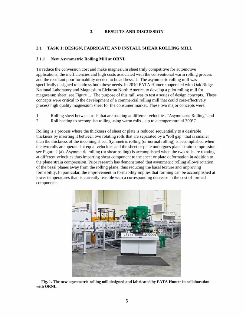
specifically designed to address both these needs. In 2010 FATA Hunter cooperated with Oak Ridge
National Laboratory and Magnesium Elektron North America to develop a pilot rolling mill for
magnesium sheet, see Figure 1. The purpose of this mill was to test a series of design concepts. These
concepts were critical to the development of a commercial rolling mill that could cost-effectively
process high quality magnesium sheet for the consumer market. These two major concepts were:
1. Rolling sheet between rolls that are rotating at different velocities-“Asymmetric Rolling” and
2. Roll heating to accomplish rolling using warm rolls – up to a temperature of 300°C.
Rolling is a process where the thickness of sheet or plate is reduced sequentially to a desirable
thickness by inserting it between two rotating rolls that are separated by a “roll gap” that is smaller
than the thickness of the incoming sheet. Symmetric rolling (or normal rolling) is accomplished when
the two rolls are operated at equal velocities and the sheet or plate undergoes plane strain compression;
see Figure 2 (a). Asymmetric rolling (or shear rolling) is accomplished when the two rolls are rotating
at different velocities thus imparting shear component to the sheet or plate deformation in addition to
the plane strain compression. Prior research has demonstrated that asymmetric rolling allows rotation
of the basal planes away from the rolling plane, thus reducing the basal texture and improving
formability. In particular, the improvement in formability implies that forming can be accomplished at
lower temperatures than is currently feasible with a corresponding decrease in the cost of formed
components.
Fig. 1. The new asymmetric rolling mill designed and fabricated by FATA Hunter in collaboration
with ORNL.

6
Preliminary work on a laboratory scale mill equipped with unequal sized rolls showed that such shear
deformation placed significantly higher demands on the torque requirements of the drivetrain and the
ability of the rolls to accommodate such large torques. The new asymmetric mill was specifically
designed with a large torque capability to accommodate a wide range of differential velocities and
shear ratios. In addition, active dynamic braking was used to maintain the large difference in roll linear
velocities. It should be noted that the mill is designed to accommodate up to a 5:1 velocity ratio with
potentially higher values achievable with smaller reductions.
(a) (b)
Fig. 2. Schematic of the (a) symmetric rolling and (b) asymmetric rolling process (adapted from [2]).
Roll heating is another key component of the newly designed mill with the potential to achieve the
desired texture and properties of the processed sheet. The deformation mode of magnesium alloys is
very strongly dependent on temperature. While the magnesium sheet can be heated to desired
operating temperatures and rolled using cold rolls, the contact of the warm sheet with the cold rolls
results in roll chilling of the sheet, resulting in unpredictable consequences for the deformation
behavior of the sheet produced using this process. While external roll heating can be accomplished,
such heating cannot be controlled easily to maintain isothermal roll temperatures. Thus this mill was
designed with internal roll heating that can be used to maintain the rolls at a desired temperature using
Proportional Integral Derivative (PID) control, thus defining the process conditions precisely. This
ability greatly enhanced the reproducibility of the process conditions, while allowing the widest
achievable process window for development.
The basic configuration of the laboratory scale mill consisted of a 2-Hi mill stand complete with
hydraulic gap control, exhaust hood, side guides and pinch rolls mounted on a sub-base. The roll
changer rails were mounted on a separate assembly that attached to the main sub-base. The mill
incorporated asymmetric drives that were mounted on a separate base and connected to the mill via
spindle couplings. The drives featured two-speed gearboxes for quick changes between the 50 and
500 feet per minute (fpm) speed range. Material handling was by means of two powered roller tables
on each side of the mill. Each roller table can be controlled individually and the drives are interlocked
and synchronized with the speed and direction of the mill. Each roller table was provided with a
hinged cover that contained a thermostatically controlled electric heater and blower motor to minimize
heat losses from the rolled strip. The main design features of the mill are summarized as follows:
The mill has H13 tool steel work rolls that were sized for the optimum combination of
o Roll neck size (for bearing capacity and roll neck shear/torsional stress),
o Roll body size (for roll rigidity and sufficient bite angle to take the required rolling
reductions),
o Contact length (to control heat transfer between the strip and the roll).
7
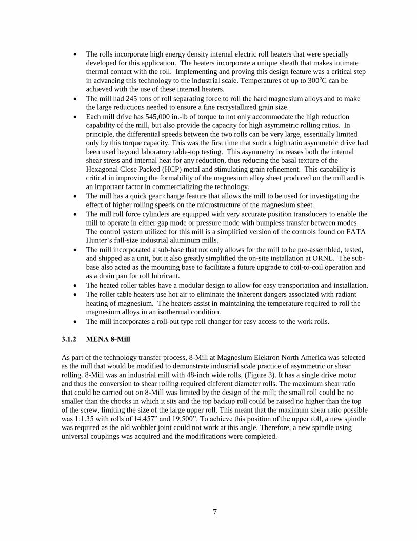
The rolls incorporate high energy density internal electric roll heaters that were specially
developed for this application. The heaters incorporate a unique sheath that makes intimate
thermal contact with the roll. Implementing and proving this design feature was a critical step
in advancing this technology to the industrial scale. Temperatures of up to 300oC can be
achieved with the use of these internal heaters.
The mill had 245 tons of roll separating force to roll the hard magnesium alloys and to make
the large reductions needed to ensure a fine recrystallized grain size.
Each mill drive has 545,000 in.-lb of torque to not only accommodate the high reduction
capability of the mill, but also provide the capacity for high asymmetric rolling ratios. In
principle, the differential speeds between the two rolls can be very large, essentially limited
only by this torque capacity. This was the first time that such a high ratio asymmetric drive had
been used beyond laboratory table-top testing. This asymmetry increases both the internal
shear stress and internal heat for any reduction, thus reducing the basal texture of the
Hexagonal Close Packed (HCP) metal and stimulating grain refinement. This capability is
critical in improving the formability of the magnesium alloy sheet produced on the mill and is
an important factor in commercializing the technology.
The mill has a quick gear change feature that allows the mill to be used for investigating the
effect of higher rolling speeds on the microstructure of the magnesium sheet.
The mill roll force cylinders are equipped with very accurate position transducers to enable the
mill to operate in either gap mode or pressure mode with bumpless transfer between modes.
The control system utilized for this mill is a simplified version of the controls found on FATA
Hunter’s full-size industrial aluminum mills.
The mill incorporated a sub-base that not only allows for the mill to be pre-assembled, tested,
and shipped as a unit, but it also greatly simplified the on-site installation at ORNL. The sub-
base also acted as the mounting base to facilitate a future upgrade to coil-to-coil operation and
as a drain pan for roll lubricant.
The heated roller tables have a modular design to allow for easy transportation and installation.
The roller table heaters use hot air to eliminate the inherent dangers associated with radiant
heating of magnesium. The heaters assist in maintaining the temperature required to roll the
magnesium alloys in an isothermal condition.
The mill incorporates a roll-out type roll changer for easy access to the work rolls.
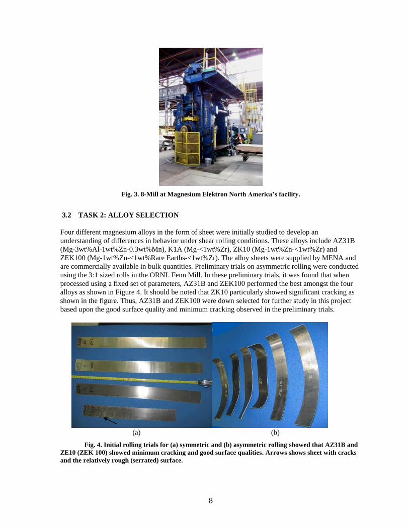
3.1.2 MENA 8-Mill
As part of the technology transfer process, 8-Mill at Magnesium Elektron North America was selected
as the mill that would be modified to demonstrate industrial scale practice of asymmetric or shear
rolling. 8-Mill was an industrial mill with 48-inch wide rolls, (Figure 3). It has a single drive motor
and thus the conversion to shear rolling required different diameter rolls. The maximum shear ratio
that could be carried out on 8-Mill was limited by the design of the mill; the small roll could be no
smaller than the chocks in which it sits and the top backup roll could be raised no higher than the top
of the screw, limiting the size of the large upper roll. This meant that the maximum shear ratio possible
was 1:1.35 with rolls of 14.457” and 19.500”. To achieve this position of the upper roll, a new spindle
was required as the old wobbler joint could not work at this angle. Therefore, a new spindle using
universal couplings was acquired and the modifications were completed.
8
Fig. 3. 8-Mill at Magnesium Elektron North America’s facility.
3.2 TASK 2: ALLOY SELECTION
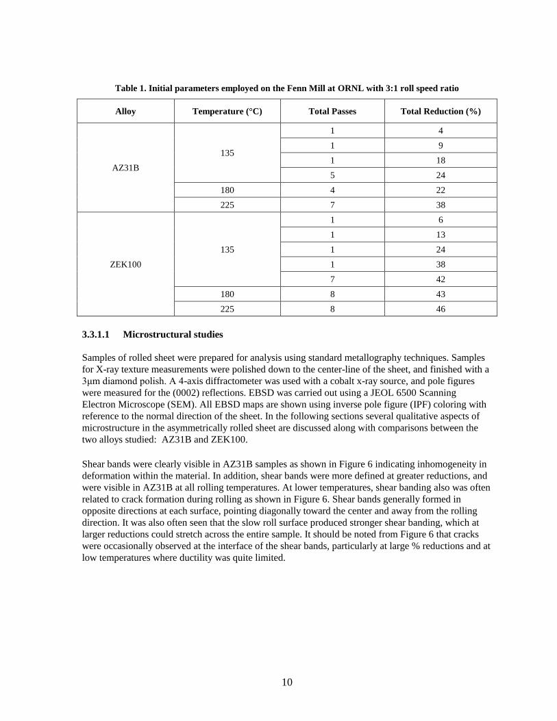
Four different magnesium alloys in the form of sheet were initially studied to develop an
understanding of differences in behavior under shear rolling conditions. These alloys include AZ31B
(Mg-3wt%Al-1wt%Zn-0.3wt%Mn), K1A (Mg-<1wt%Zr), ZK10 (Mg-1wt%Zn-<1wt%Zr) and
ZEK100 (Mg-1wt%Zn-<1wt%Rare Earths-<1wt%Zr). The alloy sheets were supplied by MENA and
are commercially available in bulk quantities. Preliminary trials on asymmetric rolling were conducted
using the 3:1 sized rolls in the ORNL Fenn Mill. In these preliminary trials, it was found that when
processed using a fixed set of parameters, AZ31B and ZEK100 performed the best amongst the four
alloys as shown in Figure 4. It should be noted that ZK10 particularly showed significant cracking as
shown in the figure. Thus, AZ31B and ZEK100 were down selected for further study in this project
based upon the good surface quality and minimum cracking observed in the preliminary trials.
(a) (b)
Fig. 4. Initial rolling trials for (a) symmetric and (b) asymmetric rolling showed that AZ31B and
ZE10 (ZEK 100) showed minimum cracking and good surface qualities. Arrows shows sheet with cracks
and the relatively rough (serrated) surface.

9
3.3 TASK 3: DEVELOP SHEAR ROLLING PROCESS
The work scope of Task 3 was to develop an understanding of the conditions required to shear roll
AZ31B and ZEK100 magnesium alloys to achieve a non-basal texture. Rolling was carried out on two
different mills available at ORNL, the Fenn Mill, and the new asymmetric rolling mill co-designed
with and built by FATA Hunter, using different rolling conditions and with different sized sheets as
explained below.
3.3.1 Fenn Mill
Fig. 5. Fenn mill, available at ORNL.
The Fenn Mill, located at ORNL, is an experimental mill with 11 inch wide rolls (Figure 5). To enable
shear rolling on this mill, it was fitted with rolls 9 inches and 3 inches in diameter, giving a
circumferential speed ratio of 3:1. It was noticed in very early experiments that a major difference
between symmetric rolling and asymmetric rolling was the curl of the sheet as it exited the mill. The
curling of sheet happens due to differential deformation across the thickness of the sheet with larger
deformation occurring on the side of the sheet in contact with the faster roll. To counteract the curl, a
stripper plate arrangement was fitted to the mill, forming a channel through which the curled sheet
travelled to restrict the natural tendency for the sheet to curve during exit. The design of the stripper
plates was part of a patent application filed with the United States Patent Office by ORNL.
Initial rolling was carried out on the Fenn Mill at ORNL using 2” wide sheet. The first trials on
AZ31B and ZEK100 were carried out using the parameters shown in Table 1. Following rolling, the
sheets were characterized for their microstructure (in particular qualitatively for grain size and shape),
homogeneity of deformation, presence/absence of recrystallization, residual deformation,
presence/absence of cracking, and basal texture. Particular emphasis was placed on understanding the
feasibility of modifying the basal texture using the asymmetric rolling conditions explored in this part
of the study.
10
Table 1. Initial parameters employed on the Fenn Mill at ORNL with 3:1 roll speed ratio
Alloy Temperature (°C) Total Passes Total Reduction (%)
AZ31B
135
1 4
1 9
1 18
5 24
180 4 22
225 7 38
ZEK100
135
1 6
1 13
1 24
1 38
7 42
180 8 43
225 8 46
3.3.1.1 Microstructural studies
Samples of rolled sheet were prepared for analysis using standard metallography techniques. Samples
for X-ray texture measurements were polished down to the center-line of the sheet, and finished with a
3μm diamond polish. A 4-axis diffractometer was used with a cobalt x-ray source, and pole figures
were measured for the (0002) reflections. EBSD was carried out using a JEOL 6500 Scanning
Electron Microscope (SEM). All EBSD maps are shown using inverse pole figure (IPF) coloring with
reference to the normal direction of the sheet. In the following sections several qualitative aspects of
microstructure in the asymmetrically rolled sheet are discussed along with comparisons between the
two alloys studied: AZ31B and ZEK100.
Shear bands were clearly visible in AZ31B samples as shown in Figure 6 indicating inhomogeneity in
deformation within the material. In addition, shear bands were more defined at greater reductions, and
were visible in AZ31B at all rolling temperatures. At lower temperatures, shear banding also was often
related to crack formation during rolling as shown in Figure 6. Shear bands generally formed in
opposite directions at each surface, pointing diagonally toward the center and away from the rolling
direction. It was also often seen that the slow roll surface produced stronger shear banding, which at
larger reductions could stretch across the entire sample. It should be noted from Figure 6 that cracks
were occasionally observed at the interface of the shear bands, particularly at large % reductions and at
low temperatures where ductility was quite limited.

11
Fig. 6. A crack formed within a shear band in AZ31B asymmetrically rolled with a shear ratio of
3:1 on the Fenn mill at 180°C with a total strain of 22%.
Rolling temperature and % reduction had a clear effect on the microstructure and recrystallization
within shear bands. Figure 7 shows the microstructure of AZ31B samples in three different specimen
conditions showing that higher temperatures and greater deformation resulted in recrystallization,
particularly within the shear bands. No significant grain growth was observed under these rolling
conditions.
(a) (b) (c)
Fig. 7. Effect of temperature and deformation on recrystallization in asymmetrically rolled
AZ31B (3:1) (a) 13% reduction at 135oC, (b) 18% at 180
oC, and (c) 38% at 225
oC.
3.3.1.2 Bulk X-ray texture measurements
X-ray texture measurements were performed on selected specimens at multiple locations through the
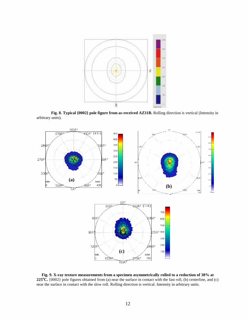
sheet thickness by sequentially polishing the specimens. Figure 8 shows a typical {0002} pole figure
from AZ31B in the as-received condition, processed using conventional symmetric rolling. Note that
the shape is essentially symmetric with respect to the rolling direction with the peak intensity close to
the center of the pole figure. Figure 9 shows the basal pole distribution obtained from the near surface
region at the slow roll, the center, and surface near the fast roll on a specimen asymmetrically rolled to
a reduction of 38% at 225oC without cracking. Note that there is an elongation in the intensity
distribution along the rolling direction and the maximum intensity orientation is tilted away from the
sheet normal towards the rolling direction. Also note that the shape changes from the surface to the
center of the specimen. These results show that the basal texture of this magnesium alloy sheet can be
successfully modified using asymmetric rolling.
Crack
12
Fig. 8. Typical {0002} pole figure from as-received AZ31B. Rolling direction is vertical (Intensity in
arbitrary units).
Fig. 9. X-ray texture measurements from a specimen asymmetrically rolled to a reduction of 38% at
225oC. {0002} pole figures obtained from (a) near the surface in contact with the fast roll, (b) centerline, and (c)
near the surface in contact with the slow roll. Rolling direction is vertical. Intensity in arbitrary units.
(a)
(b)
(c)

13
3.3.2 FATA-Hunter Mill
Eight inch wide strips were rolled on the FATA Hunter mill (see Figure 1) using the conditions shown
in Table 2. Reductions of 50% could not be achieved due to insufficient shape control at the exit side.
It was found that slower rolling gave better shape control and surface quality when compared to higher
speed asymmetric rolling. Rolled materials were characterized for their microstructure, texture, and in
selected cases, formability using the dome testing as described later in section 4.
Table 2. Rolling conditions for magnesium alloy strips rolled on the FATA Hunter mill
Alloy Roll Temperature
(°C)
Metal
Temperature (°C) Roll Speeds (rpm) Reduction (%)
AZ31B 175 175
300/300
5
7
9
10
13
27.6
300/412.5
3
6
7
8
220/604 7.5
15
AZ31B 200 200
300/300
8
15
22
42
300/405 12
200/270 15
30
200/600 16
41
280 300 300/300 10
ZEK100 200 200
300/300 14
24
200/270 15
32
200/600 12
33
14
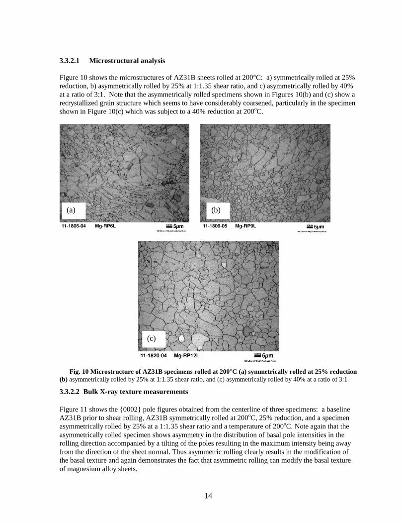
3.3.2.1 Microstructural analysis
Figure 10 shows the microstructures of AZ31B sheets rolled at 200°C: a) symmetrically rolled at 25%
reduction, b) asymmetrically rolled by 25% at 1:1.35 shear ratio, and c) asymmetrically rolled by 40%
at a ratio of 3:1. Note that the asymmetrically rolled specimens shown in Figures 10(b) and (c) show a
recrystallized grain structure which seems to have considerably coarsened, particularly in the specimen
shown in Figure 10(c) which was subject to a 40% reduction at 200oC.
Fig. 10 Microstructure of AZ31B specimens rolled at 200°C (a) symmetrically rolled at 25% reduction
(b) asymmetrically rolled by 25% at 1:1.35 shear ratio, and (c) asymmetrically rolled by 40% at a ratio of 3:1
3.3.2.2 Bulk X-ray texture measurements
Figure 11 shows the {0002} pole figures obtained from the centerline of three specimens: a baseline
AZ31B prior to shear rolling, AZ31B symmetrically rolled at 200oC, 25% reduction, and a specimen
asymmetrically rolled by 25% at a 1:1.35 shear ratio and a temperature of 200oC. Note again that the
asymmetrically rolled specimen shows asymmetry in the distribution of basal pole intensities in the
rolling direction accompanied by a tilting of the poles resulting in the maximum intensity being away
from the direction of the sheet normal. Thus asymmetric rolling clearly results in the modification of
the basal texture and again demonstrates the fact that asymmetric rolling can modify the basal texture
of magnesium alloy sheets.
(b) (a)
(c)

15
Fig. 11. X-ray texture measurements from (a) a specimen prior to asymmetric rolling, (b) symmetrically rolled at
200oC, 25% reduction, and (c) asymmetrically rolled by 25% at 1:1.35 shear ratio at a temperature of 200oC. Rolling
direction is vertical. Intensity shown is normalized to intensity from a randomly oriented specimen.
3.4 TASK 4: DEMONSTRATE SHEAR ROLLING IN AN INDUSTRIAL PROCESS
ENVIRONMENT
The scope of Task 4 was to demonstrate the feasibility of shear rolling magnesium alloy sheet in an
industrial environment and in particular to demonstrate the rolling of wider sheets on an industrial
scale mill. This was carried out at MENA using ‘8-Mill’ described earlier. Table 3 shows the matrix of
rolling trials carried out on the 8-Mill with nominal temperatures and reductions. Both symmetric (1:1)
roll speeds and asymmetric rolling was performed on this mill to understand the differences between
the microstructures and textures of sheet that were rolled using these different processing conditions.
Samples were used in formability testing as described in Section 4 and 36 inch wide sheets were also
rolled to prove that shear rolling could be scaled up to an industrial sized process as described in
section 5.

16
Table 3. Matrix of parameters used for rolling sheet using the 8-mill at MENA.
Alloy Temperature (°C) Total Passes Total Reduction (%)
AZ31B
200 1 10
200 1 25
200 1 50
250 1 10
250 1 25
250 1 50
350 1 25
425 1 10
425 1 50
ZEK100
200 1 10
200 1 25
200 1 50
250 1 10
250 1 25
250 1 50
350 1 25
425 1 10
425 1 50
It was encouraging to note that both AZ31B and ZEK100 sheets rolled using single pass reductions of
10 and 25% produced good quality sheets, with no edge cracking and a relatively flat profile, see
Figure 12 (left). At large reductions per pass (50% reduction), the shape control was much worse and a
center buckle developed during the rolling of all sheets, especially at lower temperatures, see Figure 12
(right). The AZ31B alloy also showed significant edge cracking at the lower temperatures when
compared to ZEK100.
Fig. 12. Effect of processing condition on quality of sheet produced using the 8-mill. The photograph
on the left shows ZEK100 rolled at 425°C with 10% reduction. The photograph on the right shows AZ31B
rolled at 200°C with 50% reduction.
Several practical difficulties and anomalies were encountered during the process development for the
8-mill. For example, it was observed that the curling of sheet was not always predictable. Although the
sheet was expected to curl away from the fast roll due to that surface encountering greater deformation,
this effect was not always observed. The exact cause of the absence of curling is unknown, but two
17
explanations are possible. The first is that the sheet was simply sticking to the upper roll and was being
bent after it had exited the roll gap, inducing an opposite curvature into the sheet. The second is that
there was a difference in friction between the two rolls. At the very start of rolling this was unlikely
since the rolls were ground to exactly the same finish. However, it is possible that after several passes
were carried out, a build-up of magnesium and magnesium oxide occurred on the rolls modifying the
surface finish and hence the friction coefficient. The amount of build-up is likely to be different on the
upper and lower rolls due to the difference in the speeds of the two rolls and the contact length. This
would change the friction coefficient between the roll and the material, which would alter the forces on
the sheet, causing a variation of the total shear forces. It was also observed that the rolling of the
narrow sheet and shape control was facilitated by the presence of the stripper plate.
The next task was to develop the asymmetric rolling process for wider sheets (36”) of AZ31B and
ZEK100. When scaling up to this wider sheet, more process difficulties were encountered. The main
complications were with the shape and finish of the metal. These difficulties were again related to the
direction of curling. As explained earlier, it was anticipated that the material would increase in length
on the side of the fast roll, and thus curl downwards. This behavior had been observed in previous
trials, and therefore the stripper plates were designed such that the lower plate was positioned very
close to the roll to ensure the material did not wrap around the roll. However, it was found during
rolling on 8-Mill that the material did not behave entirely as expected. In many cases, the material
curved upwards. This caused problems with the stripper plates and certain sheets came into contact
with the plate edges when they exited the mill. It was found that the positioning of the stripper plates
was critical in controlling the sheet exit process in the shear rolling mill. The stripper plates needed to
be shaped carefully and adjusted to fit less than 0.008 inches from the roll surface.
Adding lubrication/cooling to the process greatly helped to decrease the shape problems and eliminate
chatter. The narrow strips were rolled with no lubrication and thus the first wide sheets were rolled
exactly the same way. It was thought that lack of lubrication would result in higher shear stresses on
the material, due to higher friction. However, after a few sheets had been rolled, the material started to
‘chatter’ very badly through the roll bite, with alternating regions of sticking and slipping, as a result of
pickup on the rolls. This produced a very uneven surface, which was expected to give inconsistent
amounts of shear deformation. For this reason, lubrication was used for the remainder of rolling. While
there may have been more slipping at the roll surface, and consequently less shear forces applied to the
metal, the overall quality was much better and more consistent. Shape control was also improved by
the application of lubricant due to cooling of the rolls. Figure 13 shows a typical example of the type
of problem that was encountered during the rolling process. The leading edge of the sheet is shown in
the foreground. A clear line between good, flat material at the start and poorly shaped/warped material
at the end was clearly visible. The initial good section was approximately one revolution of the rolls,
and it is thought that heating from the rolls was responsible for the change in shape. The use of coolant
minimized these issues by cooling the rolls during processing. It was also found that large reductions
exacerbated the problems and it was not possible to deform greater than 25% on the wide material,
limiting the process window available. Hence thirty-six inch wide sheets of AZ31B and ZEK100 were
asymmetrically rolled nominally at 250°C with only a 10% reduction. These sheets were used for
forming automotive components as described later in the report.

18
Fig. 13. Photograph of rolled sheets showing the difference in shape control along the length.
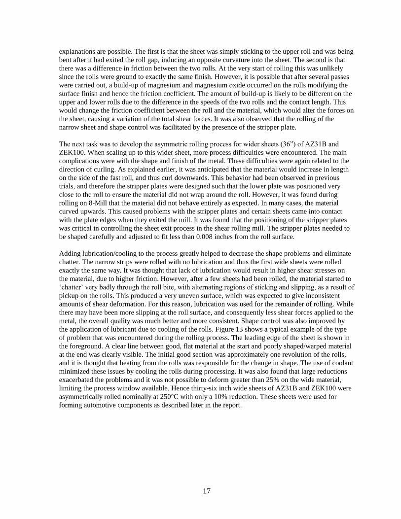
It was realized that due to unpredictable friction conditions related to the temperature and the surface
roughness that varied during the rolling process, there was a need to understand the amount of shear
actually imparted to the sheet during asymmetric rolling. Two strips of AZ31B containing drilled holes
were asymmetrically rolled on the 8-mill at 370°C, one by a 10% and the other by a 50% reduction.
The sample rolled by a 10% reduction in thickness showed a small curl downward at the beginning,
and an upward curl towards the end of the sheet whereas the sheet rolled to a 50% reduction showed a
very strong upward curl along the full length. Although the sheet rolled by a 10% reduction showed a
change in shape during rolling, the holes were found to be consistently angled in the same direction in
both areas. Sections through the holes are shown in Figure 14 and Figure 15. It can be seen that in both
samples, the hole was tilted in the direction that would be expected from a large (fast) roll on top,
despite the curl of the sheet being opposite and that the tilting is larger in the sample reduced to a
greater reduction in thickness.
Fig. 14. Section through a drilled hole in a sample deformed asymmetrically at 370°C with 10%
reduction. The top surface was in contact with the fast roll and the bottom surface with the slow roll. The
rolling direction was left to right.
19
Fig. 15. Section through a drilled hole in a sample deformed asymmetrically at 370°C with 50%
reduction. The top surface was in contact with the fast roll and the bottom surface with the slow roll. The
rolling direction was left to right.
In summary, it should be noted that although difficulties were encountered during the scale-up of the
asymmetric rolling process, both AZ31B and ZEK100 sheets were successfully rolled using the
modified 8-Mill and, as explained later, components were fabricated using the rolled sheet.
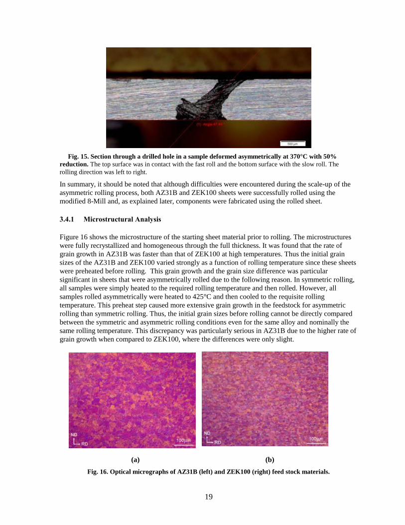
3.4.1 Microstructural Analysis
Figure 16 shows the microstructure of the starting sheet material prior to rolling. The microstructures
were fully recrystallized and homogeneous through the full thickness. It was found that the rate of
grain growth in AZ31B was faster than that of ZEK100 at high temperatures. Thus the initial grain
sizes of the AZ31B and ZEK100 varied strongly as a function of rolling temperature since these sheets
were preheated before rolling. This grain growth and the grain size difference was particular
significant in sheets that were asymmetrically rolled due to the following reason. In symmetric rolling,
all samples were simply heated to the required rolling temperature and then rolled. However, all
samples rolled asymmetrically were heated to 425°C and then cooled to the requisite rolling
temperature. This preheat step caused more extensive grain growth in the feedstock for asymmetric
rolling than symmetric rolling. Thus, the initial grain sizes before rolling cannot be directly compared
between the symmetric and asymmetric rolling conditions even for the same alloy and nominally the
same rolling temperature. This discrepancy was particularly serious in AZ31B due to the higher rate of
grain growth when compared to ZEK100, where the differences were only slight.
(a) (b)
Fig. 16. Optical micrographs of AZ31B (left) and ZEK100 (right) feed stock materials.
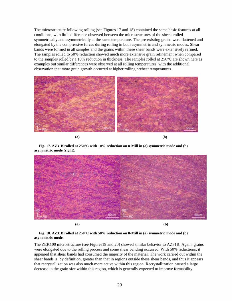
20
The microstructure following rolling (see Figures 17 and 18) contained the same basic features at all
conditions, with little difference observed between the microstructures of the sheets rolled
symmetrically and asymmetrically at the same temperature. The pre-existing grains were flattened and
elongated by the compressive forces during rolling in both asymmetric and symmetric modes. Shear
bands were formed in all samples and the grains within these shear bands were extensively refined.
The samples rolled to 50% reduction showed much more extensive grain refinement when compared
to the samples rolled by a 10% reduction in thickness. The samples rolled at 250°C are shown here as
examples but similar differences were observed at all rolling temperatures, with the additional
observation that more grain growth occurred at higher rolling preheat temperatures.
(a) (b)
Fig. 17. AZ31B rolled at 250°C with 10% reduction on 8-Mill in (a) symmetric mode and (b)
asymmetric mode (right).
(a) (b)
Fig. 18. AZ31B rolled at 250°C with 50% reduction on 8-Mill in (a) symmetric mode and (b)
asymmetric mode.
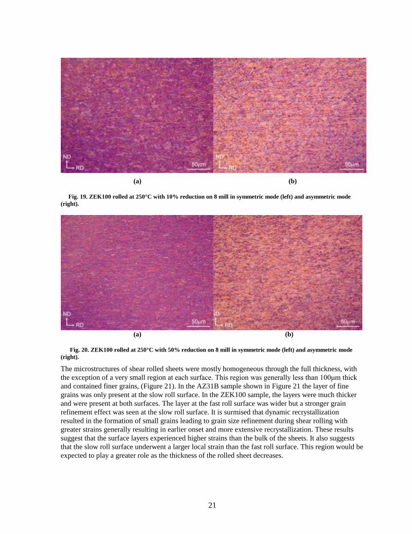
The ZEK100 microstructure (see Figures19 and 20) showed similar behavior to AZ31B. Again, grains
were elongated due to the rolling process and some shear banding occurred. With 50% reductions, it
appeared that shear bands had consumed the majority of the material. The work carried out within the
shear bands is, by definition, greater than that in regions outside these shear bands, and thus it appears
that recrystallization was also much more active within this region. Recrystallization caused a large
decrease in the grain size within this region, which is generally expected to improve formability.
21
(a) (b)
Fig. 19. ZEK100 rolled at 250°C with 10% reduction on 8 mill in symmetric mode (left) and asymmetric mode
(right).
(a) (b)
Fig. 20. ZEK100 rolled at 250°C with 50% reduction on 8 mill in symmetric mode (left) and asymmetric mode
(right).
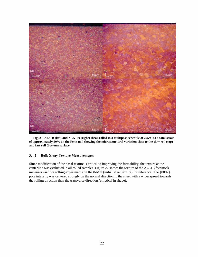
The microstructures of shear rolled sheets were mostly homogeneous through the full thickness, with
the exception of a very small region at each surface. This region was generally less than 100μm thick
and contained finer grains, (Figure 21). In the AZ31B sample shown in Figure 21 the layer of fine
grains was only present at the slow roll surface. In the ZEK100 sample, the layers were much thicker
and were present at both surfaces. The layer at the fast roll surface was wider but a stronger grain
refinement effect was seen at the slow roll surface. It is surmised that dynamic recrystallization
resulted in the formation of small grains leading to grain size refinement during shear rolling with
greater strains generally resulting in earlier onset and more extensive recrystallization. These results
suggest that the surface layers experienced higher strains than the bulk of the sheets. It also suggests
that the slow roll surface underwent a larger local strain than the fast roll surface. This region would be
expected to play a greater role as the thickness of the rolled sheet decreases.
22
Fig. 21. AZ31B (left) and ZEK100 (right) shear rolled in a multipass schedule at 225°C to a total strain
of approximately 50% on the Fenn mill showing the microstructural variation close to the slow roll (top)
and fast roll (bottom) surface.
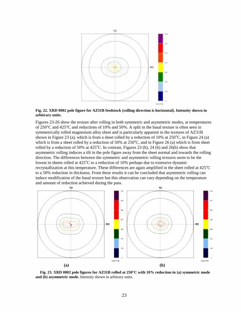
3.4.2 Bulk X-ray Texture Measurements
Since modification of the basal texture is critical to improving the formability, the texture at the
centerline was evaluated in all rolled samples. Figure 22 shows the texture of the AZ31B feedstock
materials used for rolling experiments on the 8-Mill (initial sheet texture) for reference. The {0002}
pole intensity was centered strongly on the normal direction in the sheet with a wider spread towards
the rolling direction than the transverse direction (elliptical in shape).
23
Fig. 22. XRD 0002 pole figure for AZ31B feedstock (rolling direction is horizontal). Intensity shown in
arbitrary units.
Figures 23-26 show the texture after rolling in both symmetric and asymmetric modes, at temperatures
of 250°C and 425°C and reductions of 10% and 50%. A split in the basal texture is often seen in
symmetrically rolled magnesium alloy sheet and is particularly apparent in the textures of AZ31B
shown in Figure 23 (a), which is from a sheet rolled by a reduction of 10% at 250oC, in Figure 24 (a)
which is from a sheet rolled by a reduction of 50% at 250oC, and in Figure 26 (a) which is from sheet
rolled by a reduction of 50% at 425oC. In contrast, Figures 23 (b), 24 (b) and 26(b) show that
asymmetric rolling induces a tilt in the pole figure away from the sheet normal and towards the rolling
direction. The differences between the symmetric and asymmetric rolling textures seem to be the
lowest in sheets rolled at 425oC to a reduction of 10% perhaps due to extensive dynamic
recrystallization at this temperature. These differences are again amplified in the sheet rolled at 425oC
to a 50% reduction in thickness. From these results it can be concluded that asymmetric rolling can
induce modification of the basal texture but this observation can vary depending on the temperature
and amount of reduction achieved during the pass.
(a) (b)
Fig. 23. XRD 0002 pole figures for AZ31B rolled at 250°C with 10% reduction in (a) symmetric mode
and (b) asymmetric mode. Intensity shown in arbitrary units.

24
(a) (b)
Fig. 24. XRD 0002 pole figures for AZ31B rolled at 250°C with 50% reduction in (a) symmetric mode
and (b) asymmetric mode (right). Intensity shown in arbitrary units.
(a) (b)
Fig. 25. XRD 0002 pole figures for AZ31B rolled at 425°C with 10% reduction in (a) symmetric mode
and (b) asymmetric mode (right). Intensity shown in arbitrary units.

25
(a) (b)
Fig. 26. XRD 0002 pole figures for AZ31B rolled at 425°C with 50% reduction in (a) symmetric mode
and (b) asymmetric mode (right). Intensity shown in arbitrary units.
Figure 27 shows the texture of the starting ZEK100 feedstock. It can be seen that this was very
different from that of AZ31B feedstock as shown in Figure 22. The ZEK100 showed a split of the
basal pole towards the transverse direction, and generally weaker intensities, a general texture known
as the ‘rare earth texture,’ which is generally related to improved formability3. Figures 28-31 show the
textures of sheets rolled symmetrically and asymmetrically at temperatures of 250°C and 425°C and
reductions of 10% and 50%. During rolling, the basal planes rotated along the rolling direction to
result in split in the distribution of basal planes along the rolling direction, known as a ‘standard split
basal texture’. Deformation to a greater strain, especially at the lower temperatures, led to an almost
fully standard split basal texture. Rolling in asymmetric mode caused only a small tilt with 10%
reduction; however it significantly rotates the entire texture towards the rolling direction with 50%
reductions. The maximum intensity of the pole figures is generally lower in the asymmetrically rolled
samples, indicating that the overall texture is weaker. Thus, it has been clearly demonstrated that
modification of the initial texture can be achieved in both AZ31B and ZEK100 (primarily tilting of
texture away from the sheet normal) through asymmetric rolling.
3 Jan Bohlen et al., “The texture and anisotropy of magnesium–zinc–rare earth alloy sheets,” Acta Materialia, Vol. 56, No. 7, April 2007,
p.2101-2112.

26
Fig. 27. XRD 0002 pole figure for ZEK100 feedstock. Intensity shown in arbitrary units.
(a) (b)
Fig. 28. XRD 0002 pole figures for ZEK100 rolled at 250°C with 10% reduction in (a) symmetric
mode and (b) asymmetric mode. Intensity shown in arbitrary units.

27
(a) (b)
Fig. 29. XRD 0002 pole figures for ZEK100 rolled at 250°C with 50% reduction in (a) asymmetric
mode and (b) asymmetric mode. Intensity shown in arbitrary units.
(a) (b)
Fig. 30. XRD 0002 pole figures for ZEK100 rolled at 425°C with 10% reduction in (a) symmetric mode
and (b) asymmetric mode. Intensity shown in arbitrary units.

28
(a) (b)
Fig. 31. XRD 0002 pole figures for ZEK100 rolled at 425°C with 50% reduction in symmetric mode
(left) and asymmetric mode (right). Intensity shown in arbitrary units.
3.4.3 EBSD Analysis of Microstructure
Limited EBSD work was performed on cross-sections of the samples to relate the texture observed at
small scales to the x-ray texture measurements performed on a large area of the specimen. Figure 32
shows an EBSD map on the centerline of an AZ31B sheet that was rolled symmetrically at 250°C with
10% reduction. Figure 33 shows the orientations of the grains corresponding to the colors. The
majority of grains in this map are colored red, indicating that there was a very strong basal texture. It
should be recalled that results from x-ray texture measurements shown in Figure 23(a) suggest a split-
basal texture for the same condition. The grains were mostly the same size as in the feedstock, and
many were slightly elongated, indicating that they were original, non-recrystallized grains. There were
also some much smaller grains around the original grain boundaries, most likely due to dynamic
recrystallization during rolling.
Fig. 32. EBSD map (IPF coloring) of an AZ31B sheet rolled symmetrically at 250°C with 10%
reduction (map taken at the sheet centerline.)
RD
ND
50μm
29
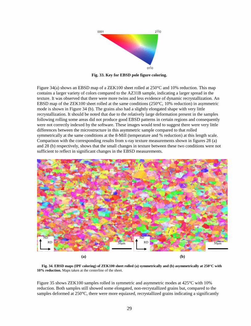
Fig. 33. Key for EBSD pole figure coloring.
Figure 34(a) shows an EBSD map of a ZEK100 sheet rolled at 250°C and 10% reduction. This map
contains a larger variety of colors compared to the AZ31B sample, indicating a larger spread in the
texture. It was observed that there were more twins and less evidence of dynamic recrystallization. An
EBSD map of the ZEK100 sheet rolled at the same conditions (250°C, 10% reduction) in asymmetric
mode is shown in Figure 34 (b). The grains also had a slightly elongated shape with very little
recrystallization. It should be noted that due to the relatively large deformation present in the samples
following rolling some areas did not produce good EBSD patterns in certain regions and consequently
were not correctly indexed by the software. These images would tend to suggest there were very little
differences between the microstructure in this asymmetric sample compared to that rolled
symmetrically at the same conditions at the 8-Mill (temperature and % reduction) at this length scale.
Comparison with the corresponding results from x-ray texture measurements shown in figures 28 (a)
and 28 (b) respectively, shows that the small changes in texture between these two conditions were not
sufficient to reflect in significant changes in the EBSD measurements.
(a) (b)
Fig. 34. EBSD maps (IPF coloring) of ZEK100 sheet rolled (a) symmetrically and (b) asymmetrically at 250°C with
10% reduction. Maps taken at the centerline of the sheet.
Figure 35 shows ZEK100 samples rolled in symmetric and asymmetric modes at 425°C with 10%
reduction. Both samples still showed some elongated, non-recrystallized grains but, compared to the
samples deformed at 250°C, there were more equiaxed, recrystallized grains indicating a significantly
RD
ND
50μm RD
ND
50μm

30
larger extent of recrystallization when compared to the rolling at 250°C. There was also less twinning
evident in these samples than those deformed at 250°C. In left side of Figure 35 at least one band of
smaller grains can be seen running diagonally across the map. This is thought to be a shear band where
the higher level of strain has initiated more dynamic recrystallization and thus decreased the grain size.
Comparison between the textures of these samples shown in Figures 30 (a) and (b) suggests that the
EBSD results are consistent with x-ray textures revealing very little difference between the textures in
symmetric and asymmetric rolled samples.
The only sample deformed to 50% reduction that has been properly studied using EBSD was a sample
of ZEK100 rolled asymmetrically at 250°C, shown in Figure 36. This study was particularly difficult
since the large deformation resulted in an EBSD pattern that was difficult to analyze, as explained
earlier. This map was carried out with a higher resolution to allow all features in the microstructure to
be analyzed. It can be seen that there were many grains in the material that had not undergone
recrystallization; those showing an elongated shape and large angle rotations across the width. There
were a larger number of fine recrystallized grains, particularly seen around grain boundaries and in
bands across non-recrystallized grains. It is thought that the bands of fine grains across other grains
were due to preferential recrystallization on either twins or slip bands. The level of twinning also
appears to have been higher in this sample than those rolled with 10% reduction.
In summary, the EBSD measurements showed results consistent with the bulk x-ray texture
measurements. The quality of the EBSD measurements was observed to be poor due to residual
deformation thus restricting the use of this technique to processing conditions that imparted little
deformation.
Fig. 35. EBSD maps (IPF coloring) of ZEK100 sheet rolled symmetrically (left) and asymmetrically
(right) at 425°C with 10% reduction. Maps taken at the centerline of the sheet.
RD
ND
RD
ND
50μm 50μm

31
Fig. 36. EBSD map (IPF coloring) of a ZEK100 sheet rolled asymmetrically at 250°C with 50%
reduction (map taken at the sheet centerline.)
RD
ND
20μm

32
33
4. FORMABILITY TESTING
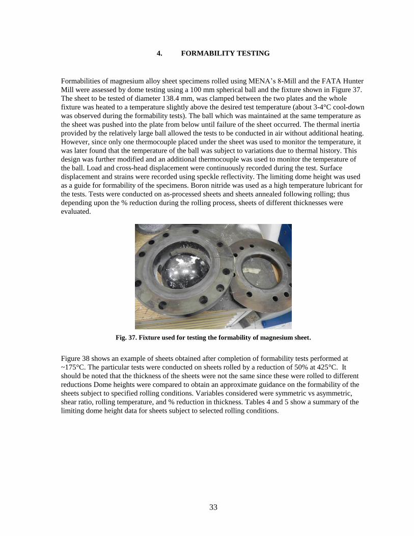
Formabilities of magnesium alloy sheet specimens rolled using MENA’s 8-Mill and the FATA Hunter
Mill were assessed by dome testing using a 100 mm spherical ball and the fixture shown in Figure 37.
The sheet to be tested of diameter 138.4 mm, was clamped between the two plates and the whole
fixture was heated to a temperature slightly above the desired test temperature (about 3-4°C cool-down
was observed during the formability tests). The ball which was maintained at the same temperature as
the sheet was pushed into the plate from below until failure of the sheet occurred. The thermal inertia
provided by the relatively large ball allowed the tests to be conducted in air without additional heating.
However, since only one thermocouple placed under the sheet was used to monitor the temperature, it
was later found that the temperature of the ball was subject to variations due to thermal history. This
design was further modified and an additional thermocouple was used to monitor the temperature of
the ball. Load and cross-head displacement were continuously recorded during the test. Surface
displacement and strains were recorded using speckle reflectivity. The limiting dome height was used
as a guide for formability of the specimens. Boron nitride was used as a high temperature lubricant for
the tests. Tests were conducted on as-processed sheets and sheets annealed following rolling; thus
depending upon the % reduction during the rolling process, sheets of different thicknesses were
evaluated.
Fig. 37. Fixture used for testing the formability of magnesium sheet.
Figure 38 shows an example of sheets obtained after completion of formability tests performed at
~175°C. The particular tests were conducted on sheets rolled by a reduction of 50% at 425°C. It
should be noted that the thickness of the sheets were not the same since these were rolled to different
reductions Dome heights were compared to obtain an approximate guidance on the formability of the
sheets subject to specified rolling conditions. Variables considered were symmetric vs asymmetric,
shear ratio, rolling temperature, and % reduction in thickness. Tables 4 and 5 show a summary of the
limiting dome height data for sheets subject to selected rolling conditions.

34
Fig. 38. Typical formed sheets obtained from dome tests on AZ31B and ZEK 100 sheets rolled at 425oC
to a 50% reduction in thickness.

35
Table 4. Effect of processing conditions on limiting dome heights at 175oC for AZ31B
Temperature
(oC)
%
Reduction
Shear
ratio
Mill Condition Final
Thickness
Stroke
Length at
Failure
(in.)
Comments
(Sheet
Processing
conditions)
250 10 1:1 8-Mill As rolled 0.086” 1.3 Preheat only
250 10 1:1 8-Mill Annealed 0.085” 0.6 Preheat only
250 10 1:1.35 8-Mill As-rolled 0.09” 0.8 Preheat only
250 10 1:1.35 8-Mill Annealed 0.09” 0.8 Preheat only
425 10 1:1 8-Mill As rolled 0.088” 0.6 Preheat only
425 10 1:1.35 8-Mill As rolled 0.088” 0.8 Preheat only
250 50 1:1 8-Mill As rolled 0.05” 1.4 Preheat only
250 50 1:1.35 8-Mill As rolled 0.064” 0.9 Preheat only
425 50 1:1 8-Mill As rolled 0.046” 0.9 Preheat only
425 50 1:1.35 8-Mill As rolled 0.051” 0.4 Preheat only
200 10 1:1 FATA As rolled 0.092” 0.9 Isothermal
200 10 1:1.35 FATA As rolled 0.087” 1.2 Isothermal
200 10 1:3 FATA As rolled 0.096” 0.8 Isothermal
200 25 1:1 FATA As rolled 0.079” 1.3 Isothermal
200 25 1:1.35 FATA As rolled 0.071” 1.1 Isothermal

36
Table 5. Effect of processing conditions on limiting dome heights at 175oC for ZEK100
Temperature
(oC)
%
Reduction
Shear
ratio
Mill Condition Final
thickness
Stroke
Length at
Failure
(in.)
Comments
(Sheet processing
conditions)
250 10 1:1 8-Mill Rolled 0.084” 1.6 Preheat only
250 10 1:1 8-Mill Annealed 0.084” 1.6 Preheat only
250 10 1:1.35 8-Mill As-rolled 0.092” 1.6 Preheat only
250 10 1:1.35 8-Mill Annealed 0.092” 1.6 Preheat only
425 10 1:1 8-Mill As rolled 0.089” 1.4 Preheat only
425 10 1:1.35 8-Mill As rolled 0.089” 1.5 Preheat only
250 50 1:1 8-Mill As rolled 0.05” 1.5 Preheat only
250 50 1:1.35 8-Mill As rolled 0.05” 1.5 Preheat only
425 50 1:1 8-Mill As rolled 0.05” 1.1 Preheat only
425 50 1:1 8-Mill Annealed 0.05” 1.5 Preheat only
425 50 1:1.35 8-Mill As rolled 0.05” 1.1 Preheat only
425 50 1:1.35 8-Mill Annealed 0.05” 1.5 Preheat only
200 10 1:1 FATA As rolled 0.088” 1.6 Isothermal
200 10 1:1.35 FATA As rolled 0.083” 1.4 Isothermal
200 10 1:3 FATA As rolled 0.087 1.3 Isothermal
200 25 1:1 FATA As rolled 0.076” 1.2 Isothermal
200 25 1:1.35 FATA As rolled 0.069” 1.4 Isothermal
37
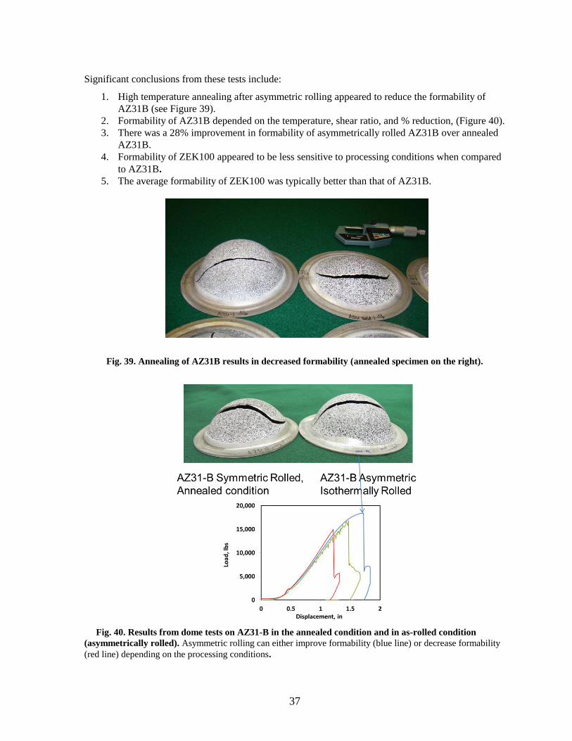
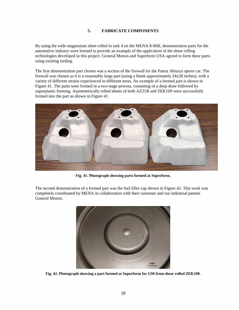
Significant conclusions from these tests include:
1. High temperature annealing after asymmetric rolling appeared to reduce the formability of
AZ31B (see Figure 39).
2. Formability of AZ31B depended on the temperature, shear ratio, and % reduction, (Figure 40).
3. There was a 28% improvement in formability of asymmetrically rolled AZ31B over annealed
AZ31B.
4. Formability of ZEK100 appeared to be less sensitive to processing conditions when compared
to AZ31B.
5. The average formability of ZEK100 was typically better than that of AZ31B.
Fig. 39. Annealing of AZ31B results in decreased formability (annealed specimen on the right).
Fig. 40. Results from dome tests on AZ31-B in the annealed condition and in as-rolled condition
(asymmetrically rolled). Asymmetric rolling can either improve formability (blue line) or decrease formability
(red line) depending on the processing conditions.

38
39
5. FABRICATE COMPONENTS
By using the wide magnesium sheet rolled in task 4 on the MENA 8-Mill, demonstration parts for the
automotive industry were formed to provide an example of the application of the shear rolling
technologies developed in this project. General Motors and Superform USA agreed to form these parts
using existing tooling.
The first demonstration part chosen was a section of the firewall for the Panoz Abruzzi sports car. The
firewall was chosen as it is a reasonably large part (using a blank approximately 24x28 inches), with a
variety of different strains experienced in different areas. An example of a formed part is shown in
Figure 41. The parts were formed in a two-stage process, consisting of a deep draw followed by
superplastic forming. Asymmetrically rolled sheets of both AZ31B and ZEK100 were successfully
formed into the part as shown in Figure 41.
Fig. 41. Photograph showing parts formed at Superform.
The second demonstration of a formed part was the fuel filler cap shown in Figure 42. This work was
completely coordinated by MENA in collaboration with their customer and our industrial partner
General Motors.
Fig. 42. Photograph showing a part formed at Superform for GM from shear rolled ZEK100.

40
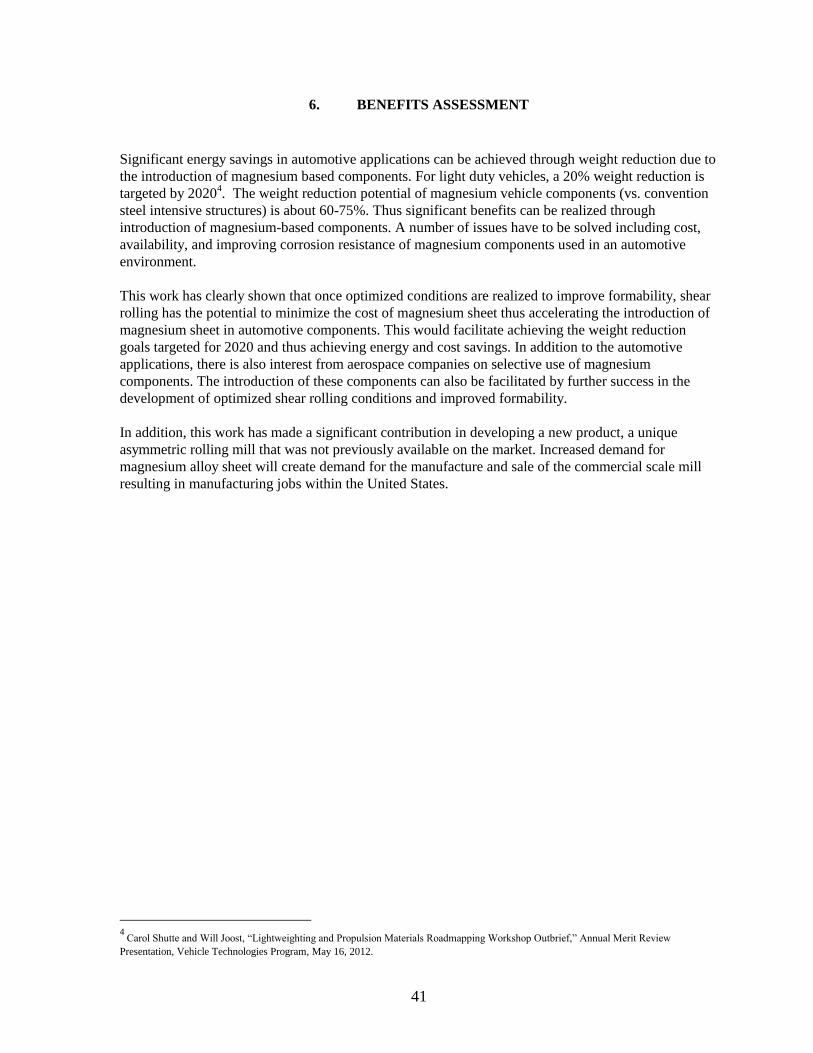
41
6. BENEFITS ASSESSMENT
Significant energy savings in automotive applications can be achieved through weight reduction due to
the introduction of magnesium based components. For light duty vehicles, a 20% weight reduction is
targeted by 20204. The weight reduction potential of magnesium vehicle components (vs. convention
steel intensive structures) is about 60-75%. Thus significant benefits can be realized through
introduction of magnesium-based components. A number of issues have to be solved including cost,
availability, and improving corrosion resistance of magnesium components used in an automotive
environment.
This work has clearly shown that once optimized conditions are realized to improve formability, shear
rolling has the potential to minimize the cost of magnesium sheet thus accelerating the introduction of
magnesium sheet in automotive components. This would facilitate achieving the weight reduction
goals targeted for 2020 and thus achieving energy and cost savings. In addition to the automotive
applications, there is also interest from aerospace companies on selective use of magnesium
components. The introduction of these components can also be facilitated by further success in the
development of optimized shear rolling conditions and improved formability.
In addition, this work has made a significant contribution in developing a new product, a unique
asymmetric rolling mill that was not previously available on the market. Increased demand for
magnesium alloy sheet will create demand for the manufacture and sale of the commercial scale mill
resulting in manufacturing jobs within the United States.
4
Carol Shutte and Will Joost, “Lightweighting and Propulsion Materials Roadmapping Workshop Outbrief,” Annual Merit Review
Presentation, Vehicle Technologies Program, May 16, 2012.

42

43
7. COMMERCIALIZATION
The following commercialization steps have already been accomplished:
1. A patent application has been filed by ORNL for fixturing and process development.
2. Based upon the developments achieved in this project, a new commercial scale asymmetric
rolling mill has been made available for purchase by FATA Hunter. The design for FATA
Hunter’s pilot scale shear rolling mill received an R&D 100 award in 2012.
Several additional steps will be pursued to commercialize this technology.
3. New asymmetric rolling processes being developed using the installed mill have shown
significant promise in modifying the formability of AZ31B sheet. Patents will be filed as is
appropriate and the processing conditions will be transferred to entities that are interested in
licensing these patents. These included mill manufacturers like FATA Hunter, material
suppliers such as MENA, and end-users in the automotive supply chain.
4. Materials with modified texture will be made available to material suppliers such as MENA
and potential end-users such as vehicle OEM manufacturers for them to independently
evaluate formability.
5. Peer-reviewed publications will be submitted to aid in the commercialization process. Other
means to disseminate information, such as flyers, and exhibits at trade shows will be utilized
in the commercialization process.

44

45
8. ACCOMPLISHMENTS
• Laboratory-scale asymmetric rolling of shear rolling of magnesium sheet was demonstrated using
3:1 rolls producing 2-inch wide sheet with modified texture
• One patent application has been filed by ORNL for new fixture and process development
• Tilting of basal poles away from the sheet normal direction was clearly demonstrated by
asymmetric rolling
• A unique asymmetric rolling mill equipped with warm rolls for isothermal rolling was designed,
manufactured, and installed at ORNL
• A commercial scale mill designed for high throughput manufacture of asymmetrically rolled
Mg-alloy sheet based upon this mill by industrial partner (FATA Hunter) won an R & D 100
award as one of the most significant new products of the year. FATA Hunter has submitted
quotations for the new mill design to many commercial entities interested in purchase of new
large mills
• Eight-inch wide sheet has been rolled at ORNL using the newly installed mill
• Texture modification using asymmetric rolling was clearly demonstrated for sheet rolled
using the new mill
• Improved formability in biaxial testing was initially demonstrated for specific asymmetric
rolling processing conditions. These conditions will be evaluated for patentability
• An existing industrial scale mill was modified, and the feasibility of shear rolling wide sheet for
commercial use was demonstrated at MENA’s facility
• New technology (U. S. patent application submitted) developed at ORNL was implemented in
the modification of the mill
• Wide sheet was produced using the newly modified mill
• Keynote presentation was delivered by MENA staff at the TMS Annual Meeting in March
2012.
• Two demonstration automotive components, a firewall and a fuel cap filter, were fabricated using
wide sheet manufactured at MENA

46
47
9. CONCLUSIONS
1. A new asymmetric rolling mill was successfully designed and fabricated by ORNL and FATA
Hunter. This mill won an award as one of the top 100 products developed in 2011 (R & D 100
award given in 2012).
2. Based upon preliminary rolling trials, commercial magnesium alloys AZ31B (with no rare
earth additions) and ZEK100 (with rare earth additions) were selected for further evaluation.
3. Magnesium alloys AZ31B and ZEK100 were successfully rolled in symmetric and asymmetric
modes on three different mills with a wide range of processing parameters:
a. Larger reductions caused worse shape control during rolling. Over 25% reduction did
not produce acceptable sheets.
b. ZEK100 could be rolled at lower temperatures than AZ31B.
c. Shear rolling caused the sheet to exit the mill with a substantial curl that can be in
either direction. Curling was controlled by a specially designed fixture (Patent
Pending).
d. Lubrication was required to roll wider sheet.
4. Sheet microstructure was characterized using optical microscopy and EBSD
a. Shear bands were visible in most rolled samples, more defined in AZ31B than
ZEK100.
b. Shear bands in shear rolled material were generally angled into the center of the
material away from the rolling direction.
c. There was little difference between the grain structure of samples rolled symmetrically
and asymmetrically.
d. A layer of fine grains was often observed at the surface of the sheets, particularly in
the shear rolled material.
e. It appears that the slow roll surface underwent more shear strain than the fast roll
surface during asymmetric rolling.
f. There was less dynamic recrystallization in ZEK100 than AZ31B.
g. Dynamic recrystallization generally occurred at grain boundaries, twins and
deformation bands.
h. Twinning was observed in all samples.
5. The sheet texture was analyzed using XRD and EBSD
a. In AZ31B, lower temperatures and greater reductions of rolling often produced a
weaker texture.
b. Asymmetric rolling resulted in substantial tilting of the basal texture towards the
rolling direction in AZ31B.
c. Rolling changed the texture in ZEK100 to a more standard split basal texture.
d. Asymmetric rolling with higher reductions significantly altered the texture in
ZEK100.
e. The texture was relatively homogeneous through the full thickness of the sheets, with
the exception of a thin layer present at the surfaces of some samples.
6. Formability of the sheets was assessed by dome testing at 180°C. Limiting dome heights were
used as guidance for formability. Processing conditions had a significant effect (both positive
and negative) on limiting dome heights.

48
7. Demonstration parts for automotive applications were successfully formed from shear rolled
AZ31B and ZEK100 using sheets processed using conditions developed in this project.

10. RECOMMENDATIONS FOR FURTHER WORK
6.1 PHASE 2: DESIGN FOR COIL-TO-COIL OPERATION
The FATA Hunter mill at ORNL was designed such that the pilot mill could be upgradable to allow
coil-to-coil operation. This option includes the addition of hot coilers, with their associated pinch
rolls, deflector rolls, and threading aprons, as well as an entry/exit reel assembly with coil car, a
cooling unit and an upgrade to the mill control system for coiler tension control, plus miscellaneous
items such as work roll brushes and hydraulic system upgrades. As with the roller tables, the hot coiler
boxes are heated with recirculated hot air to eliminate the dangers of radiant heating.
In this coil to coil configuration, a slab of preheated magnesium would be placed on one of the roller
tables and rolled in a reversing manner until it reaches a thickness of 0.25 in. (6mm). At this point it is
guided into one of the hot coilers and is then rolled in the coil-to-coil mode until the desired thickness
is reached. By selecting the correct starting roller table and pass schedule the final gauge is reached
when the mill is running from the left- hand coiler. On this final pass the strip is guided past the right-
hand hot coiler to the cooler and then the entry/exit reel assembly. The cooler quenches the material to
prevent grain growth in the slowly cooling coil. Cooling is through a water spray followed by an air
knife to remove water from the strip surface; any remaining water being immediately evaporated by the
residual heat in the strip prior to coiling. Air cooling, however, is available as an option. The finished
coil is then removed from the mandrel by means of the coil car. The coil car has an integral hold-down
snubber roll to provide stability to the narrow coil. The coil is then removed from the coil car using a
forklift truck or overhead crane.
Although the mill can work with slab as described above, it is more likely to be used with twin roll cast
material. In that case a 0.25 in. (6mm) thick coil of room temperature magnesium is placed onto the
coil car by means of a forklift truck or overhead crane. The coil is then loaded onto the mandrel of the
entry/exit reel assembly and the coil is unwound through the mill (which operates in a pinch roll mode)
into the left-hand hot coiler. The metal is then preheated to the rolling temperature in the coil box
before starting the coil-to-coil rolling process outlined in method (1) above. Alternatively, to improve
mill efficiency, the initial 0.25 in. (6mm) coil could be pre-heated off line and then loaded onto the coil
car. While considerable progress was made during this project, more detailed studies are required to
optimize shear rolling process for industrial practice. In order to more fully develop commercial shear
rolling of magnesium more detailed study is needed.
6.2 ASYMMETRIC ROLLING PROCESS DEVELOPMENT AND EVALUATION
The following are suggested future work for process development and process evaluation.
1. A thorough parametric study is needed to understand the effect of % reduction, temperature, and
shear ratio on the development of texture.
2. Effect of complex combination of processing paths (in contrast to simple paths outlined above) on
texture development should be evaluated.
3. Effect of rare earth elements additions to alloys in # 1 and # 2 should be evaluated.
4. Effect of initial microstructure (in particular the grain size and initial texture) on #1, #2, and #3
outlined above should be evaluated.
5. The effects of processing and composition variables on formability should be better understood.
49