cover page title of design a portable wingtip collision avoidance...
TRANSCRIPT
COVER PAGE
Title of Design: The Wingman – A Portable Wingtip Collision Avoidance
System
Design Challenge Addressed: IV. Airport Management and Planning
University Name: University of Rhode Island
Team Members Names: Christopher Clark
Kyle DellaGrotta
Lawrence Higgins
David Powers
Ronald Wheeler
Number of Undergraduates: 5
Number of Graduates: 0
Advisors Names: Bahram Nassersharif
Carl-Ernst Rousseau
Valerie Maier-Speredelozzi

2013-2014 FAA Design Competition
“The Wingman”
A Portable Wingtip Collision Avoidance System
Team Members
Christopher Clark – Market Analysis
Kyle DellaGrotta – Mechanical Design
Lawrence Higgins – Cost Analysis
David Powers – Electrical Design
Ronald Wheeler – Team Leader/Coordinator
Faculty Advisors
Professor Bahram Nassersharif
Professor Carl-Ernst Rousseau, P.E.
Professor Valerie Maier-Speredelozzi
Sponsor
Rhode Island Airport Corporation
Submission Date
April 18, 2014

ii
Executive Summary
This design project report outlines the process used to conceptualize, analyze, and
fabricate a portable wingtip collision avoidance system. The project is part of the 2013-2014
FAA Design Competition for Universities and was conducted as a part of the Mechanical,
Industrial and Systems Engineering Capstone Design course at the University of Rhode Island.
This design team consists of three mechanical engineering undergraduates and two industrial and
system engineering undergraduates. The sponsor of this project is the Rhode Island Airport
Corporation.
Wingtip collisions in hangar and apron areas of airports remain a significant problem in
airport operations. This design is intended to reduce the occurrence of hangar rash and other
wingtip related collisions. This solution would have a significant effect on overall cost savings
in both the general and commercial aviation industries, as well as increase overall airport safety.
The proposed solution to this problem uses a temporary wingtip mounted device that
incorporates ultrasonic sensors as a method of proximity detection. The user of this device will
be warned of proximity to nearby objects by the use of LED lighting, which displays different
colors corresponding to the range of proximity. At close distances, not only will the red LED
indication blink rapidly, but an alarm will also alert the operator of an imminent collision. This
device will act as an aid during normal tugging and moving operations and must be removed
before flight.
This portable wingtip collision avoidance system, “The Wingman”, has potential to
significantly decrease the frequency of wingtip collisions in airport hangars, taxi, and apron
areas. With the help of the Rhode Island Airport Corporation, the design team created a
prototype that successfully detects imminent wingtip collisions. It has been demonstrated that
The Wingman will be an effective tool when implemented in the aviation industry.

iii
Contents
1 Problem Statement and Background ....................................................................................... 1
1.1 Defining the Problem .................................................................................................... 1
1.2 Prior Work and Considerations ..................................................................................... 1
1.3 Effect on the Industry ................................................................................................... 2
1.4 Proposed Solution ......................................................................................................... 2
2 Summary of Literature Review ............................................................................................... 3
2.1 FAA Competition Goals ............................................................................................... 3
2.2 Wingtip Collision Causes ............................................................................................. 4
2.3 Wingtip Collision Incidents .......................................................................................... 4
2.4 Patent Search ................................................................................................................. 5
2.5 Methods of Wingtip Collision Prevention .................................................................... 6
3 Team’s Problem Solving Approach ........................................................................................ 8
3.1 Concept Generation and Selection ................................................................................ 8
3.2 Testing ........................................................................................................................ 13
4 Safety Risk Assessment ......................................................................................................... 17
5 Technical Aspects .................................................................................................................. 19
5.1 Mechanical .................................................................................................................. 20
5.2 Electrical ..................................................................................................................... 25
6 Description of Interactions .................................................................................................... 26
7 Description of Projected Impacts .......................................................................................... 30
8 Appendices ............................................................................................................................ 35
Appendix A – Contact Information .................................................................................. 35
Appendix B – Description of University .......................................................................... 36

iv
Appendix C – Non-University Partners ............................................................................ 37
Appendix D – Sign-off Form ............................................................................................ 38
Appendix E – Evaluation of Experience ........................................................................... 39
Appendix F – Reference List ............................................................................................ 43

v
List of Figures
Figure 1: Cost of Boeing 737 ramp damage. .................................................................................. 2
Figure 2: Main effect plot for hang time (min). ............................................................................ 14
Figure 3: Interaction plot for hang time (min). ............................................................................. 15
Figure 4: Interval plot of hang time. ............................................................................................. 15
Figure 5: Ultrasonic sensor mapping (inches). ............................................................................. 16
Figure 6: The Wingman being used during a tugging operation. ................................................. 17
Figure 7: Suction cup base. ........................................................................................................... 20
Figure 8: Tube and swivel............................................................................................................. 20
Figure 9: Device leveled on angled surface. ................................................................................. 21
Figure 10: Removable plate. ......................................................................................................... 21
Figure 11: Circuit and sensor housing. ......................................................................................... 22
Figure 12: The Wingman. ............................................................................................................. 23
Figure 13: Machined tripod base. ................................................................................................. 24
Figure 14: Prototype circuit. ......................................................................................................... 25
Figure 15: Printed circuit board. ................................................................................................... 26
Figure 16: CMSgt Ballard talks with the team. ............................................................................ 27
Figure 17: James Warcup explains wing geometries. ................................................................... 28
Figure 18: Mounting the base to the Cessna. ................................................................................ 29
Figure 19: Operator using The Wingman. .................................................................................... 30
Figure 20: Locations of ramp incidents. ....................................................................................... 31
Figure 21: AOPA insurance quotes based on flight experience. .................................................. 33
vi
List of Tables
Table 1: Design specifications. ..................................................................................................... 10
Table 2: Cost of ultrasonic detection system. ............................................................................... 11
Table 3: Team’s budget. ............................................................................................................... 12
Table 4: Mass production cost savings. ........................................................................................ 13
Table 5: Test Matrix...................................................................................................................... 13

1
1 Problem Statement and Background
1.1 Defining the Problem
Wingtip collisions have a wide variety of causes as well as levels of severity. They occur in taxi,
hangar, and runway areas, and are a problem in both General Aviation (GA) and Commercial Aviation.
The operator in GA taxi and hangar areas is generally a tug driver pulling the plane with an external
vehicle or tow bar. In runway areas the plane is more likely to be under its own power and be operated
by the pilot. The causes of these incidents, although varying, can often be traced back to a loss of
situational awareness by the operator in either of these situations.
Tug drivers experience difficulty in tight hangar environments when planes must be placed very
close to each other in order to fit efficiently. It is often quite difficult for the driver to know exactly how
close they are to the other planes. This can often result in minor accidents and hangar rash, which can
nevertheless become dangerous if the tug driver does not report the incident for fear of reprimand.
In many cases, especially in smaller airports, the tug driver is not an employee of the airport, but
a GA pilot who moves their own plane. This creates a situation where a pilot with minimal or no training
is moving through hangar doors and around other planes with little to no assistance from personnel, all
the while expected to park very close to other planes.
1.2 Prior Work and Considerations
The issue of hangar rash and wingtip collisions can be and has been approached from many
different angles. These include the installation of permanent camera systems, recommended by the
National Transportation Safety Board (NTSB) to the FAA in September 2012. The FAA rejected this
recommendation on March 29, 2013, citing the additional cost of the permanent camera systems from
both installation and negative effects on fuel efficiency (Broderick, 2013).
Comprehensive approaches to this issue, such as implementing systems of safety and risk
management have also been considered. This includes standard operating procedures and systems

2
Figure 1: Cost of Boeing 737 ramp damage.
designed to avoid risk throughout processes of taxiing as well as parking within hangars. Although these
measures can be effective and are important, they have not eliminated the risk, as can be seen through
major incidents that have occurred recently at Los Angeles airport (McFadden, 2014) and Logan airport
in Boston (WCVB, 2014). These incidents show that additional tools may also be useful in solving this
issue. The reluctance of the FAA to force costly permanent systems upon airlines has in many ways
stifled interest in wingtip detection systems.
1.3 Effect on the Industry
The cost of even a small number of significant wingtip collisions can be enormous for an airline.
Ramp damage costs for a Boeing 737 are shown in Fig. 1 and represent a small amount of a typical
incident’s losses. Other indirect costs such as the cost of cancellations, loss of public image, and
investigations can be far greater or
more impactful than the direct physical
damage. (Vandel, 2004)
The cost for GA pilots,
although clearly on a smaller scale
than that of commercial accidents, is
also a significant burden on the
industry. Smaller scale incidents such
as hangar rash are frequent but also
more likely to go unreported in hopes of avoiding responsibility. Nevertheless, the occurrence of such
incidents can cost thousands of dollars due to various replacement fees.
1.4 Proposed Solution
The solution detailed in this report is a removable wingtip collision avoidance system. A device
that can be safely and easily attached and detached from the wingtip will be able to alert the operator of

3
proximity to nearby objects and increase situational awareness. This novel approach introduces a tool
that can be incorporated into efforts to increase safety and lower operating costs in the aviation industry
and represents a new approach to a persistent problem. It avoids the significant disadvantages of
permanent systems and could be implemented in various forms for both GA and commercial purposes.
2 Summary of Literature Review
2.1 FAA Competition Goals
The primary goal of the FAA Design Competition is to challenge teams of undergraduate and
graduate students to develop innovative solutions to common aviation problems. The solutions address
environmental issues and constraints, and methods to improve the management, safety, capacity and
efficiency of the nation’s airports (FAA, 2014).The competition strives to:
- Raise awareness of the benefits of Next Generation Air Transportation Systems (NextGen).
- Increase academic involvement in NextGen operations.
- Actively engage students in the conceptualization of applications, systems and equipment that
address the issues and needs of the National Airspace System (FAA, 2014).
With national involvement from universities through the competition, the FAA is better suited to
recruit individuals who can ensure the safety and development of aviation. The FAA is currently
responsible for regulating civil aviation as a whole, developing and operating an air traffic control and
navigation system, and regulating aircraft noise and other environmental effects. They are ultimately
tasked with providing a framework for a safe and viable aviation system. As a leader in the international
community, “the [American] Agency is responsive to the dynamic nature of customer needs, economic
conditions, and environmental concerns (FAA, 2014).” Additionally, the agency seeks to spur advanced
research of potential benefits to long-term growth of the aviation community. The Design Competition
is one of many ways that the FAA can invest in future engineers and innovators that will shape the
future of the technologically developing aviation community.
4
2.2 Wingtip Collision Causes
Wingtip collisions have varying causes and degrees of severity. Tug drivers, the primary
individuals who move the aircraft, experience difficulty in tight hangar environments when planes must
be placed in very close proximity to each other. Many GA hangars do not have specific regulations
mandating a certain clearance between aircraft (Murphy, 2007). These close-quarters operations
drastically increase the likelihood of an incident. Another frequently encountered problem specific to a
tug driver is the issue of blind spots while executing backwards turns. In this situation, the tug driver
often loses sight of the far wing of the plane and simply has to estimate its position based on prior
experience and knowledge.
Although the GA community does not have a centralized directive for ground operations, the
commercial industry does. Current FAA regulations require the use of wing walkers aside each wing of
an aircraft while it is being pushed back from airport gates (FAA Regulations, 2013). The personnel
carry wands to signal the level of danger to the operator using various motions and gestures. In some
situations, including military operations, whistles are used as a method of audible warning when there is
no visual contact between the tug operator and the wing walkers. Despite these efforts, the issue of
wingtip collisions has not been resolved—especially in the GA community which does not require any
formal safety precautions.
2.3 Wingtip Collision Incidents
Wingtip collisions are all too frequent and a burden on the aviation community. Every incident
results in a loss of time and money for customers, operators, and owners. At present, there are 27,000
recorded ramp incidents each year in commercial aviation, equal to approximately 1 for every 1,000
departures (Flightcom, 2013). GA faces a similar situation, but most incidents go unrecorded. Collisions
on a small scale between aircraft and hangar walls occur daily and incur large costs for repairs as stated
previously.

5
Commercial collisions have occurred quite frequently, some within the past couple of months.
On February 18, 2014, a commercial jet wing clipped a deicing truck while taxiing at Logan airport in
Boston. In a formal statement, U. S. Airways declared that none of the 99 passengers on board were
hurt, although there was minor scrape damage to the aircraft itself. Passengers were forced to board
different aircraft in order to continue on their way to Philadelphia. Before the aircraft is deemed
operable again, it must undergo a thorough inspection and the scrape damage must be repaired (WCVB,
2014). On February 27, 2014, two Qantas aircraft collided at Los Angeles International Airport while
being towed from their hangars. Although no passengers were on board, an assessment of the damage
resulted in the cancellation of one of the flights intended to go to Sydney, Australia, stranding 600
passengers. Passengers at the airport were accommodated with hotel rooms and alternate flights at the
expense of the airline (McFadden, 2014).
2.4 Patent Search
Thorough research was conducted to find relevant patents involving proximity detection and
avoidance systems. These concepts strongly correlate to proximity systems that could aid in and
alleviate the concerns of wingtip collisions. Three significant patents were found and subsequently
investigated. U.S. Patent 4,139,848, an “Aircraft proximity warning indicator”, is dated February 13,
1979. The inventor, Richard F. Maxwell Jr., provides a method for an aircraft to provide proximity
warning to a second aircraft using radio frequency signals and optical sensors. “An aircraft proximity
warning indicator incorporating an RF receiver, optical sensor, and display is described which may
receive an RF signal followed by an optical radiation pulse from another aircraft where the received RF
signal is used to control the optical sensor and display so that it senses and displays the optical radiation
pulse (U.S. Patent #4,139,848, 2013).” This patent demonstrates that this portable collision avoidance
system could use radio frequency signals to sense objects in its path.
6
U.S. Patent 6,118,401, an “Aircraft ground collision avoidance system and method”, is dated
September 12, 2000. The inventor, Bruce Tognazzini, created a method for avoiding collisions between
the wingtips of an aircraft and other objects during operations when the aircraft is on the ground. “A
system and method for avoiding collision between objects and wingtips of an aircraft when the aircraft is
on the ground includes mounting detecting devices such as a low cost radar unit and a video camera in
the wingtip. These detection devices are coupled with one or more indicators to provide an operator of
the aircraft such as a pilot that an imminent collision with an object is about to occur. The indication can
be an audio or visual signal, either within or outside of the aircraft (U.S Patent #6,118,401, 2013).” This
patent was extremely appropriate to the design of wingtip collision avoidance systems as a whole. More
specifically, the research suggested using radar and a video camera mounted to an aircraft wingtip in
order to detect objects in a given path of interest. The abstract also suggested an audio and visual
warning signal in order for the operator to avoid collisions with the given object.
U.S. Patent 7,379,165, a “Ground vehicle collision prevention systems and methods”, circa May
27, 2008, is the property of The Boeing Company. Like the previous patent described, it details a system
comprised of a proximity detection unit with a coupled alarm device that responds to its own signals.
The abstract specifically describes a method to prevent collisions between aircraft on the ground and
ground service vehicles constantly moving around the area of the aircraft. Additionally, it requires a
proximity alarm based upon the distance of the detection (U.S. Patent #7,379,165, 2013).
2.5 Methods of Wingtip Collision Prevention
As it stands, the primary method of wingtip collision prevention is the use of wing walkers and
other visual and audible aids. For commercial airlines, these tools are required and ensure the safety of
passengers and operators while tugging and moving aircraft. Although the use of wing walkers does
drastically reduce wingtip collisions, some systems have been suggested or developed in order to further
alleviate this issue. As mentioned previously, the NTSB implored the FAA to consider implementing
7
permanent proximity detection units on the wingtips of all large, commercial aircraft. This would
eliminate the need for such stringent regulations regarding wing walkers and would act as another
method to prevent incidents (Broderick, 2013).
Since this permanent solution was rejected by the FAA due to fuel efficiency concerns, other
mechanisms have been explored. A system known as “WingWatch” utilizes temporarily mounted
cameras at various locations on large aircraft. Computer vision techniques including stereoscopy and
simultaneous localization and mapping are employed to map out an aircraft’s position and warn if it is in
close proximity to other objects. The system uses a vehicle that is always nearby the aircraft in order to
render and interpret the camera data. It is not currently used because it was not deemed viable and is
prohibitively expensive (Trinity College, 7).
Other hangars use specific and unique systems to prevent collisions. Talon Air, Inc. developed a
system in which infrared lasers line the hangar walls, eight feet from the ground. If any part of the plane
contacts this detectable area, an alarm is triggered and all operations are stopped. Since the infrared laser
grid is so high, normal worker operations commence uninhibited. Founder Adam Katz noted that
incidents are simply too costly, too damaging, and too time consuming (Infanger, 2011).
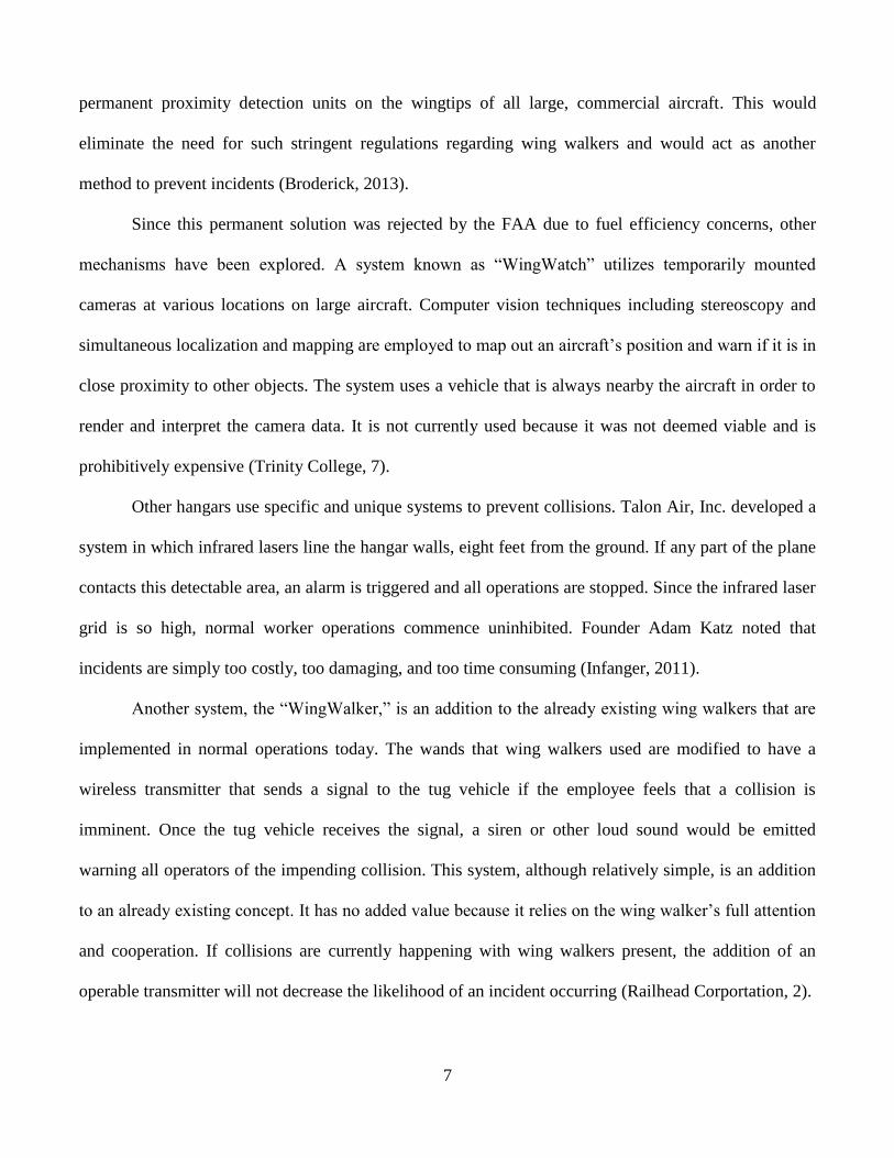
Another system, the “WingWalker,” is an addition to the already existing wing walkers that are
implemented in normal operations today. The wands that wing walkers used are modified to have a
wireless transmitter that sends a signal to the tug vehicle if the employee feels that a collision is
imminent. Once the tug vehicle receives the signal, a siren or other loud sound would be emitted
warning all operators of the impending collision. This system, although relatively simple, is an addition
to an already existing concept. It has no added value because it relies on the wing walker’s full attention
and cooperation. If collisions are currently happening with wing walkers present, the addition of an
operable transmitter will not decrease the likelihood of an incident occurring (Railhead Corportation, 2).
8
3 Team’s Problem Solving Approach
Once the team was formed it sought to efficiently divide tasks and responsibilities. Based on
individual strengths, it was decided that the mechanical and electrical design was to be completed
mainly by the mechanical engineering students while the marketing and budget analysis would go to the
industrial and systems engineering students. Ronald Wheeler was chosen as team leader based on
professional experience and management ability. The team leader was tasked with motivating the team,
distributing work as needed and ensured that project goals and deadlines were met. To make sure the
team stayed on track, a Gantt chart was created using Microsoft Project. This was used to schedule tasks,
monitor progress, and was created and updated accordingly throughout this project.
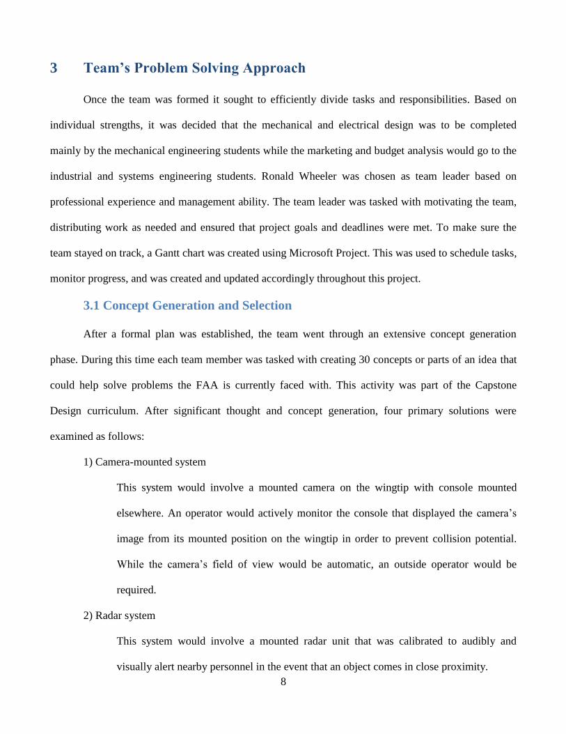
3.1 Concept Generation and Selection
After a formal plan was established, the team went through an extensive concept generation
phase. During this time each team member was tasked with creating 30 concepts or parts of an idea that
could help solve problems the FAA is currently faced with. This activity was part of the Capstone
Design curriculum. After significant thought and concept generation, four primary solutions were
examined as follows:
1) Camera-mounted system
This system would involve a mounted camera on the wingtip with console mounted
elsewhere. An operator would actively monitor the console that displayed the camera’s
image from its mounted position on the wingtip in order to prevent collision potential.
While the camera’s field of view would be automatic, an outside operator would be
required.
2) Radar system
This system would involve a mounted radar unit that was calibrated to audibly and
visually alert nearby personnel in the event that an object comes in close proximity.

9
3) Boundary and mounted optical sensor system
In this set-up, boundary lines (using high-grade asphalt paint) would be established on
relevant taxiways. Downward facing optical sensors would be mounted on the underside
of each wing. The sensors would be calibrated to detect if the wingtip crossed over the
boundary line. By means of this system, the plane would be limited to travel within pre-
established pathways.
4) Ultrasonic system
Similar to the previous mounted systems, this would use ultrasonic sensors in order to
detect the range of nearby objects. It would be calibrated to alert nearby personnel if an
object came too close in proximity to the wingtip.
The pros and cons of each detection method were heavily weight. The biggest disadvantage of
the camera system was increased distraction since the tug driver would need to monitor a video screen.
This is similar to concern pilots had when the NTSB made the recommendation to the FAA regarding
mandatory wingtip collision avoidance system installation in all aircraft (Longley, 2013).
Also, a preliminary financial analysis was conducted for each of the systems. Although the
camera and radar systems were similar in price, the boundary and mounted optical sensor system would
incur extensive additional charges in order to adequately establish painted boundaries. The paint
required to properly cover T. F. Green Airport in Rhode Island would cost approximately $15,000. Due
to its simplicity, cost, and ease of implementation, the ultrasonic detection system was pursued.
While the final concept was chosen, it needed to be further refined. Due to concern about
damaging the wings, brought up by the team’s sponsors, the initial idea of a clamping mechanism was
eliminated and suction cups were chosen as an attachment method. In addition, a list of design
specifications was developed and served as the target values that The Wingman system could achieve.
Table 1 lists the parameters and target values. Each value correlates with design criteria suggested by the
10
sponsor and from individual determinations. The most critical specifications pertained to the attachment
and detection mechanisms.
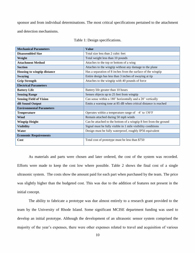
Table 1: Design specifications.
Mechanical Parameters Value
Disassembled Size Total size less than 2 cubic feet
Weight Total weight less than 10 pounds
Attachment Method Attaches to the top or bottom of a wing
Suction Attaches to the wingtip without any damage to the plane
Housing to wingtip distance Has a separation of 8 inches from the surface of the wingtip
Swaying Entire design has less than 3 inches of swaying at tip
Grip Strength Attaches to the wingtip with 40 pounds of force
Electrical Parameters
Battery Life Battery life greater than 10 hours
Sensing Range Senses objects up to 25 feet from wingtip
Sensing Field of Vision Can sense within a 180˚ horizontally and a 20˚ vertically
dB Sound Output Emits a warning tone at 85 dB when critical distance is reached
Environmental Parameters
Temperature Operates within a temperature range of -4˚ to 130˚F
Wind Remain attached during 50 mph winds
Wingtip Height Can be attached to the bottom of a wingtip 8 feet from the ground
Visibility Signal must be fully visible in 1 mile visibility conditions
Water Design must be fully waterproof, roughly IP56 equivalent
Economic Requirements
Cost Total cost of prototype must be less than $750
As materials and parts were chosen and later ordered, the cost of the system was recorded.
Efforts were made to keep the cost low where possible. Table 2 shows the final cost of a single
ultrasonic system. The costs show the amount paid for each part when purchased by the team. The price
was slightly higher than the budgeted cost. This was due to the addition of features not present in the
initial concept.
The ability to fabricate a prototype was due almost entirely to a research grant provided to the
team by the University of Rhode Island. Some significant MCISE department funding was used to
develop an initial prototype. Although the development of an ultrasonic sensor system comprised the
majority of the year’s expenses, there were other expenses related to travel and acquisition of various

11
materials. Table 3 outlines the full budget for the completion of the system, showing that the estimated
cost for the production of one set of ultrasonic detection units is $1,141. The department funding of
$350 and the URI Research Grant of $1,400 proved to be essential and completely funded the design,
fabrication, and testing of the product.
Table 2: Cost of ultrasonic detection system.
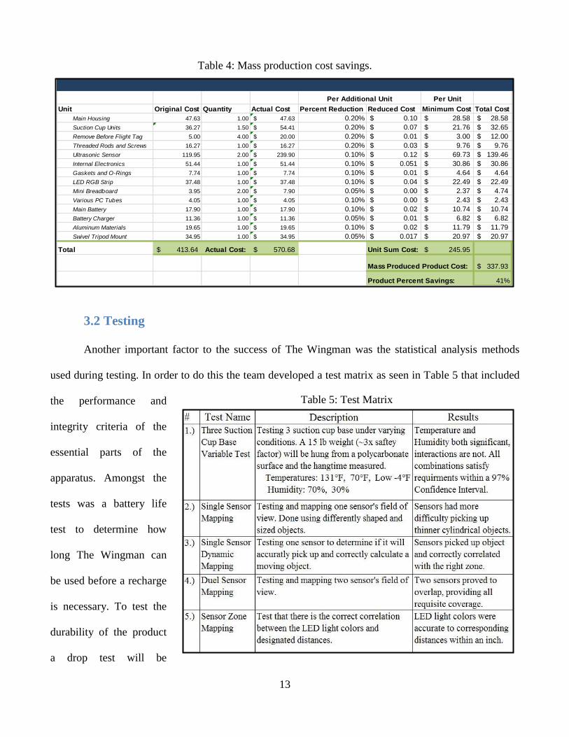
Email correspondence with a MaxBotix representative revealed that the ultrasonic sensor, a
major cost, would be reduced from $119.95 each to $69.73 each with an order quantity of 1,000 units.
Using this quote, reduced cost per unit was determined. Table 4 displays potential mass production cost
savings, showing each unit at the original price, the quantity needed to produce a single complete
product, and the corresponding actual cost. The percent reduction in cost per additional unit purchased is
an estimation based on the quote obtained from MaxBotix. The audible alarm, battery holder,

12
breadboard, and suction cup air valves are already very inexpensive and will likely not decrease in price
as more units are purchased. Since the ultrasonic sensor was approximately 60% of its original cost
when 1,000 units were purchased, similar cost reduction methods were assumed for other major
components. The anticipated minimum cost of materials is $337.93, a 41% decrease in cost when
compared to the cost of producing a single unit.
Table 3: Team’s budget.
FAA Team 5 BUDGETFall Semester 2013 4/10/2014 21:41
SUMMARY ACTUAL BUDGETED OVER BUDGET UNDER BUDGET
Total income 1,750.00 1,900.00 -150.00
Total expenses 1,574.08 1,710.00 -135.92
Income less expenses: 175.92 190.00 -14.08
INCOME DETAILS ACTUAL BUDGETED OVER BUDGET UNDER BUDGET NOTES
URI Grant 1,400.00 1,400.00 Grant from COE
Department Funding 350.00 500.00 -150.00
Total income: 1,750.00 1,900.00 -150.00
EXPENSE DETAILS ACTUAL BUDGETED OVER BUDGET UNDER BUDGET NOTES
TRAVEL
Trips to TF Green 120.00 150.00 -30.00
Trips to Quonsett 20.00 50.00 0.00 -30.00
Other 30.00 50.00 -20.00 Trip to local airport in Middletow n
Total sales expenses: 170.00 250.00 -80.00
Percent of total: 10.80% 14.62%
DEVELOPING PROTOTYPE
In-class Demo 17.96 20.00 -2.04
Square Wooden Dowel 1.99 4.00 -2.01
Foam for the wing 7.79 4.00 3.79
Grey Spray Paint 4.19 4.00 0.19
LED Xmas Lights 3.99 4.00 -0.01
Initial Prototype 209.76 310.00 -100.24
Final Prototype (2 units) 1,141.36 1,090.00 51.36
Main Housing 47.63 40.00 7.63 Hexagonal, ABS and Support
Suction Cup Units 54.41 15.00 39.41 Hand-held Suction Cup Lifter
Remove Before Flight Tag 20.00 20.00 RBF4
Threaded Rods and Screws 16.27 25.00 -8.73 Various Size Rods
Ultrasonic Sensor 239.90 250.00 -10.10 MB7363 HRXL-MaxSonar-WRLS
Internal Electronics 51.44 50.00 1.44 Arduino and Wiring Units
Gaskets and O-Rings 7.74 5.00 2.74 Various Sizes, Super-Soft
LED RGB Strip 37.48 45.00 -7.52 Bare (5 meter)
Mini Breadboard 7.90 5.00 2.90 Mini Modular (Red)
Various PC Tubes 4.05 20.00 -15.95 Various Thicknesses, 1' Units
Main Battery 17.90 10.00 7.90
Battery Charger 11.36 10.00 1.36
Aluminum Materials 19.65 15.00 4.65 6" by 6" by 1/2" 6061 Aluminum
Swivel Tripod Mount 34.95 35.00 -0.05 Quick Release w ith Ballhead
Total Prototype expenses: 1,369.08 1,420.00 -50.92
Percent of total: 86.98% 83.04%
MISCELLANEOUS
Notebooks 10.00 10.00
Project Notebook 25.00 30.00 -5.00
Total M iscellaneous expenses: 35.00 40.00 -5.00
Percent of total: 2.22% 2.34%
13
Table 5: Test Matrix
Table 4: Mass production cost savings.
3.2 Testing
Another important factor to the success of The Wingman was the statistical analysis methods
used during testing. In order to do this the team developed a test matrix as seen in Table 5 that included
the performance and
integrity criteria of the
essential parts of the
apparatus. Amongst the
tests was a battery life
test to determine how
long The Wingman can
be used before a recharge
is necessary. To test the
durability of the product
a drop test will be
Per Unit
Unit Original Cost Quantity Actual Cost Percent Reduction Reduced Cost Minimum Cost Total Cost Units to Achieve Min Cost
Main Housing 47.63 1.00 47.63$ 0.20% 0.10$ 28.58$ 28.58$ 200
Suction Cup Units 36.27 1.50 54.41$ 0.20% 0.07$ 21.76$ 32.65$ 200
Remove Before Flight Tag 5.00 4.00 20.00$ 0.20% 0.01$ 3.00$ 12.00$ 200
Threaded Rods and Screws 16.27 1.00 16.27$ 0.20% 0.03$ 9.76$ 9.76$ 200
Ultrasonic Sensor 119.95 2.00 239.90$ 0.10% 0.12$ 69.73$ 139.46$ 419
Internal Electronics 51.44 1.00 51.44$ 0.10% 0.051$ 30.86$ 30.86$ 400
Gaskets and O-Rings 7.74 1.00 7.74$ 0.10% 0.01$ 4.64$ 4.64$ 400
LED RGB Strip 37.48 1.00 37.48$ 0.10% 0.04$ 22.49$ 22.49$ 400
Mini Breadboard 3.95 2.00 7.90$ 0.05% 0.00$ 2.37$ 4.74$ 800
Various PC Tubes 4.05 1.00 4.05$ 0.10% 0.00$ 2.43$ 2.43$ 400
Main Battery 17.90 1.00 17.90$ 0.10% 0.02$ 10.74$ 10.74$ 400
Battery Charger 11.36 1.00 11.36$ 0.05% 0.01$ 6.82$ 6.82$ 800
Aluminum Materials 19.65 1.00 19.65$ 0.10% 0.02$ 11.79$ 11.79$ 400
Swivel Tripod Mount 34.95 1.00 34.95$ 0.05% 0.017$ 20.97$ 20.97$ 800
Total 413.64$ Actual Cost: 570.68$ Unit Sum Cost: 245.95$
Mass Produced Product Cost: 337.93$
Product Percent Savings: 41%
Mass Production Cost Savings
Per Additional Unit
14
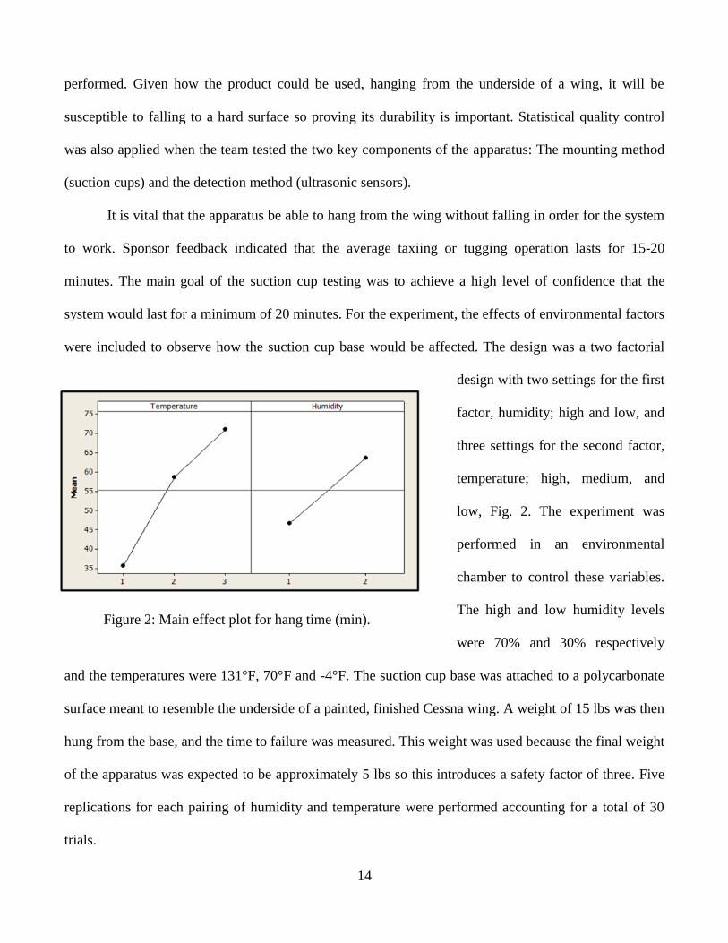
Figure 2: Main effect plot for hang time (min).
performed. Given how the product could be used, hanging from the underside of a wing, it will be
susceptible to falling to a hard surface so proving its durability is important. Statistical quality control
was also applied when the team tested the two key components of the apparatus: The mounting method
(suction cups) and the detection method (ultrasonic sensors).
It is vital that the apparatus be able to hang from the wing without falling in order for the system
to work. Sponsor feedback indicated that the average taxiing or tugging operation lasts for 15-20
minutes. The main goal of the suction cup testing was to achieve a high level of confidence that the
system would last for a minimum of 20 minutes. For the experiment, the effects of environmental factors
were included to observe how the suction cup base would be affected. The design was a two factorial
design with two settings for the first
factor, humidity; high and low, and
three settings for the second factor,
temperature; high, medium, and
low, Fig. 2. The experiment was
performed in an environmental
chamber to control these variables.
The high and low humidity levels
were 70% and 30% respectively
and the temperatures were 131°F, 70°F and -4°F. The suction cup base was attached to a polycarbonate
surface meant to resemble the underside of a painted, finished Cessna wing. A weight of 15 lbs was then
hung from the base, and the time to failure was measured. This weight was used because the final weight
of the apparatus was expected to be approximately 5 lbs so this introduces a safety factor of three. Five
replications for each pairing of humidity and temperature were performed accounting for a total of 30
trials.

15
Figure 3: Interaction plot for hang time (min).
Figure 4: Interval plot of hang time.
The results of the suction cup testing were analyzed using Minitab. A general linear model
analysis of variance (ANOVA) test was used. The information gathered demonstrated that both humidity
and temperature had P-values of
0.000, indicating that both factors
had a significant effect on the hang
time, depicted in Fig. 3.
Clearly, the suction cup
base works best in a warm and
humid environment. The
interaction between humidity and
temperature proved to be
insignificant as the P-value was .248. Fig. 4 shows the interaction plot for the suction-cup hang time.
Perhaps the most important analysis performed was the confidence interval test. As mentioned
before, it was important that the
apparatus could hang for 20
minutes regardless of the
environmental factors. The
results were encouraging
because at both 95% and 97%
confidence, every pairing of
humidity and temperature had a
lower end of their range that
exceeded 20 minutes. The 99% confidence interval indicates that the lower ranges of all the
combinations exceed a minimum of 15 minutes. The low humidity had a very negative effect on suction-

16
Figure 5: Ultrasonic sensor mapping (inches).
cup effectiveness causing the range to drop below 20 minutes. The tests were considered to be a success
however, passing a 97% confidence test with a safety factor of 3.
The other major component tested was the ultrasonic sensors used in The Wingman’s design.
There were a few different tests completed with different objectives. The “mapping” of a single sensor
needed to be completed in order to verify the detection capabilities. Multiple objects of varying size and
material were slowly moved into the sensor’s field of view until the objects were detected. When an
object was finally detected, a physical point was marked at the given distance from the sensor. After
single sensor testing, dual-sensor testing commenced to determine how the sensors would interact with
each other. The test of the
single sensor mapping is
shown in Fig. 5. The two
objects used during this
test were a 1” diameter
pole and a human being.
The results were very
encouraging. The coverage
was slightly better than
advertised, especially in
mid-ranged regions where high performance is most essential. The dual-sensor testing proved even
better; multiple detection points appeared to be advantageous. Pulses emitted from one sensor could be
received by the other, meaning a broader range of detection. The tests were a huge success and proved
that the two sensors would be sufficient in providing the necessary coverage. Further, it was beneficial
to use statistical methods to prove the concepts of the product. All of the results were excellent and
demonstrated that the product would function as designed.

17
As a final test, the team took the device to Quonset State Airport to perform some field testing.
The device was mounted to a Cessna and tugged by an operator around the hanger as seen in Fig. 6. The
Wingman was successful in that it helped the operator take the plane out of the hanger without any
incidents; every time the wing was close to another aircraft or hangar wall the device signaled the
operator.
Figure 6: The Wingman being used during a tugging operation.
4 Safety Risk Assessment
The product in and of itself will increase safety in the airline industry by helping to avoid
incidents in hangar and taxi areas. The overall effect of the design on the industry would, without a
doubt, be to increase safety. However, to ensure the actual safety of the product, a number of
considerations were necessary. Among these was the decision to have a “null output,” which is the blue
LED indication shown in Fig. 6. This informs the user that the sensor is active, but not sensing anything.
Another consideration is the use of suction cups as opposed to clamps to attach the device to the wing.
This will reduce the possibility of the device damaging the surface of the wing as low as possible.
To manage the safety of all potential operators the team went through the five phases of the SRM
process; describe the system, identify the hazards, determine the risk, assess and analyze the risk, and
treat the risk (FAA, 2007).
18
One identified concern with the device is the potential that an operator could leave it attached to
the wing and attempt to take off with the device still attached. While this potential cannot be entirely
eliminated, the red color that the entire housing and base will be covered with will help to mitigate this
effect. In addition, flags saying “Remove Before Flight” were placed on the object. During a pilot's pre-
flight routine, which includes a checklist, the pilot must ensure that they have removed all red, Remove
Before Flight items from the plane; this includes covers for the engine intakes and pitot tubes.
OSHA requirements and standards were considered when designing The Wingman. Due to
OSHA requirements, most workers need to be connected to a ladder with a karabiner or other fastener in
order to climb it. To avoid these additional steps and increased risks, the device was designed to be
mounted from the ground with no additional equipment necessary. Regulatory compliance as it relates to
worker safety was also considered. The National Institute for Occupational Safety and Health (NIOSH)
handbook showed that the allowable weight lifted by worker is based on a large number of factors,
including distance from the weight to body, quality of grips on the object, range of motion required, and
frequency of task. These factors each reduce the amount of permissible weight of the object. The
maximum weight given how the product will be used was found to be roughly 20lbs (NIOSH, 2009).
Given the device weight of roughly 7 lbs, it will be safe for the intended use.
During sponsor interaction, the prospect was raised that such a device could potentially damage
the wingtip surface. This obviously needed to be avoided and was a key factor in the design revisions, as
well as being included in the design specifications in Table 1. Previously, the idea of a clamp system had
been considered for attachment. After careful consideration, the team chose a suction-based mounting
method. As shown in the Problem Solving Approach section, proving the safety and duration of the
suction cup system was a key part of testing.
As mentioned in the FAA website’s SMS document safety promotion includes training and
education, safety communication, and safety competency and continues improvement (FAA, 2007). To

19
ensure that the team promotes safety, a detailed instructional manual will be included and a training
course or video would be mandatory before using the product. This is also an effective way to mitigate
many of the other perceived risks, such as the device falling on a person.
5 Technical Aspects
The chosen concept is a product that will be able to prevent wingtip collisions between aircraft
and other objects or vehicles during pushback, tugging, and towing operations. At first, this concept was
designed to be a universal portable wingtip collision avoidance system that would function on many
types of aircraft. The best ultrasonic sensor would be chosen and the housing would be designed around
that. The housing as well as the sensor would have to be weather resistant to be as universal as possible.
A sound and visual warning system would have to be created to alert operators of an imminent collision,
and all of this would then have to be attached to an aircraft wing by some attachment method. Intensive
research was performed in order to determine what would be suitable for each of these subsections of
the design.
After a meeting with the Rhode Island Air National Guard (RIANG) and a second and third
meeting with the Rhode Island Airport Corporation, different design aspects were identified and a
specific target market was chosen. This portable wingtip collision avoidance system’s design was
designed for the GA market. This market is composed of civilian pilots who often fly small planes out of
local airports as a hobby. Most often, the portable wingtip collision avoidance system would be used by
the pilot or a GA airport employee when moving smaller aircraft, such as a Cessna, into or out of a
hangar or around the tarmac. This would eliminate any wingtip collisions and the costs related to them
during these operations.
The design of this device can be broken up into two general categories: electrical and
mechanical. The electrical design consists of sensors, detection methods, and circuitry, while the
mechanical design consists of the mounting solution and housing geometry.

20
Figure 7: Suction cup base.
Figure 8: Tube and swivel.
5.1 Mechanical
The first mechanical component of the design of
this portable wingtip collision avoidance system is the
attachment system. This is the part of the product that
attaches to the wingtip of the aircraft. It consists of a
simple tripod design, shown in Fig. 7, machined out of
half inch thick aluminum plate with a 3 inch diameter suction cup mounted to each of the three
legs.(Suction Cups, 2013)
As mentioned in the Safety Risk Assessment, the suction cup attachment method was chosen and
designed because of its ease of use and non-damaging characteristics. Using the suction cups as an
attachment method would also allow for mounting on the top or bottom of the aircraft wing, depending
upon wing height and user preference. If the wing height is low, the product should be placed on the top
of the wing to ensure better visibility, and vice verse for a higher wing. The tripod suction design would
balance the weight of the other components of the system, would create much more gripping force, and
would help to eliminate unwanted swaying of the system. There are also many different cup size options
to vary grip force and total assembly footprint size. Also seen in Fig. 7, vacuum release valve pins are
used in combination with “Remove Before Flight” finger
loops in order for the user to easily pull down and dismount
the suction base.
The next component of this design is a spacing tube
and swivel mount as shown in Fig. 8. The suction tripod could
not be placed close to the edge to avoid the ailerons in the
back and heavy curvature in the front of the wingtip. Once
21
Figure 10: Removable plate.
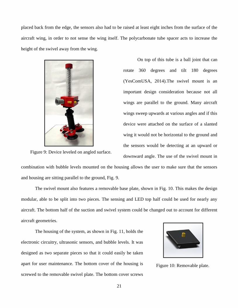
Figure 9: Device leveled on angled surface.
placed back from the edge, the sensors also had to be raised at least eight inches from the surface of the
aircraft wing, in order to not sense the wing itself. The polycarbonate tube spacer acts to increase the
height of the swivel away from the wing.
On top of this tube is a ball joint that can
rotate 360 degrees and tilt 180 degrees
(YesComUSA, 2014).The swivel mount is an
important design consideration because not all
wings are parallel to the ground. Many aircraft
wings sweep upwards at various angles and if this
device were attached on the surface of a slanted
wing it would not be horizontal to the ground and
the sensors would be detecting at an upward or
downward angle. The use of the swivel mount in
combination with bubble levels mounted on the housing allows the user to make sure that the sensors
and housing are sitting parallel to the ground, Fig. 9.
The swivel mount also features a removable base plate, shown in Fig. 10. This makes the design
modular, able to be split into two pieces. The sensing and LED top half could be used for nearly any
aircraft. The bottom half of the suction and swivel system could be changed out to account for different
aircraft geometries.
The housing of the system, as shown in Fig. 11, holds the
electronic circuitry, ultrasonic sensors, and bubble levels. It was
designed as two separate pieces so that it could easily be taken
apart for user maintenance. The bottom cover of the housing is
screwed to the removable swivel plate. The bottom cover screws

22
Figure 11: Circuit and sensor housing.
onto to the main housing using six screws that mount into housing wall. The main body of the housing
has two holes for the sensors and an on-off switch.
The housing utilizes a partial hexagonal geometry with
interior angles of 120 degrees to point proximity
sensors in the proper direction and house all of the
wiring, circuitry, and electronics that are used in this
system. Having flat walls instead of curved surfaces
allows for easier sealing with o-rings. The bottom
cover is also sealed with a waterproof gasket. The housing is placed either forward or aft on the wingtip,
depending on the maneuvering that will be done. If necessary, one can be placed in each direction.
These sensors being used, MB7363 HRXL from MaxBotix, are weather resistant and have a
detection range of up to 30 feet. The detection angle is 60 degrees at 4 feet and 30 degrees at distances
beyond 4 feet. These sensors are highly waterproof and have an operational temperature of -40°F to
149°F. They are very energy efficient, with a low current draw, and easy to incorporate into a
circuit.(Maxbotix, MB 7363 Data Sheet, 2013) The mounting hardware consists of a steel lock nut, a
Buna-N o-ring, and a neoprene o-ring.(Maxbotix, Mounting Harware, 2013) This will completely seal
the sensor in the housing and prevent unwanted moisture or contaminants from entering the electronics
portion of the housing. The MB7363 sensors were chosen because of their weather resistance as well as
their detection range. They are the highest performing outdoor weather resistant sensors matching the
affordability and capabilities designated in the design specifications and budget.
On top of the housing there are two impact resistant polycarbonate tubes along with a threaded
rod and aluminum cap. The top of the main circuit housing features two circular indentations in order to
line up the two polycarbonate tubes. The inner tube is painted black and has a sealed LED strip wrapped
tightly around it. The outer tube is clear and has an outer diameter of 1 ¾”. Next, the transparent outer

23
Figure 12: The Wingman.
tube is placed over both the inner tube and the LED lights that are wrapped around it. This will serve as
protection for the LEDs from any rain, wind, or snow to which this system will be subjected when being
used outside at an airport.
The LED strip contains 60 RGB LEDs per meter and is sealed with a waterproof flexible silicon
jacket (Fun, 2013). An aluminum cap puts pressure on the tops of the inner and outer tube to press them
tightly into the top of the housing. The indents will feature o-rings in all of the circular indents to
provide a watertight seal. An aluminum threaded rod run through the center of the tubes into the
housing. A nut then securely compresses the inner and outer tubes between the aluminum cap and the
top of the housing. The top cap, main housing, and suction cup base assembly are all painted bright red
for increased visibility while the base also features “Remove Before Flight” streamers (Spruce, 2014).
The decision to use Remove Before Flight streamers
is a result of suggestions from James Warcup, one of the
team’s sponsor contacts. Many aircraft add-on accessories,
such as pitot tube covers and engine plugs, are used while
the aircraft is parked to enhance safety and decrease
maintenance. However, these accessories are not meant to
be used during takeoff or flight. If forgotten and left on,
many of these accessories can cause catastrophic failures to
the aircraft while trying to take off or even during flight.
The visual design features of this portable collision
avoidance system greatly enhance aircraft and user safety
and are incorporated to remind the user to remove the
system from the wing before trying to fly. The full
assembled system can be seen in Fig. 12.

24
Figure 13: Machined tripod base.
The weight of this product is an important part of the design specifications. The portability of the
product was obviously heavily dependent on weight. The need to not damage the wing of the plane also
encouraged the team to keep weight as low as possible. While designing the components of this system,
material selection was just as important as the dimensions. For this reason, a total weight calculation was
performed using the mass properties toolbars within SolidWorks. This was used to obtain a preliminary
weight calculation. After fabrication, one unit weighs 7 pounds, which corresponds to weight estimated
by the software.
Overall, four of these portable wingtip collision avoidance systems would be included in a heavy
duty Pelican case as full kit. The pelican case is model 1730, is 34” by 24” by 12.50” (Pelican, 2013). It
is waterproof, crushproof, and dust proof, and it features an o-ring seal, polyurethane wheels with
stainless steel bearings, and fold down handles. This case keeps the systems fully protected during
transport or storage and will be convenient for the user.
Fabrication of the entire portable wingtip collision avoidance system was completed at the
University of Rhode Island machine shop located in Gilbreth Hall with the guidance of URI machinists.
Learning how to operate various machines such as the
milling machine, the lathe, and the vertical band saw
helped the team immensely when fabricating
components throughout the entirety of the project.
The housing was designed using SolidWorks and then
fabricated by a 3D printing machine. When
assembling for mass production, an injection molding process will be used instead of 3D printing in
order to increase durability and structural integrity. The aluminum tripod suction base was machined for
the team using the SolidWorks models and CNC, shown in Fig. 13.
All the impact resistant polycarbonate tubes were cut to the desired length using the vertical band

25
Figure 14: Prototype circuit.
saw and then faced off using the lathe. The lathe was also used to machine the aluminum tube cap. The
design of this portable wingtip collision avoidance system utilizes many parts that are “off the shelf”
components offered in many different standard sizes. This allows for flexibility in the design process
and easy switches in the case where a component needs to be changed slightly to allow for better fit or
better performance in the system. The components that are considered off the shelf in this design include
the suction cups, hollow tubing, LED strip, screws, o-rings, and rods. Most of the specific dimensions in
the housing and mounting assembly are taken from the dimensions and tolerances of these components
and they are all standard sizes that can be easily found online or at local hardware shops.
5.2 Electrical
The most distinctive aspect of the electrical and circuit approach taken to this project is the
choice of ultrasonic sensors to detect other objects. There are a number of advantages to this approach.
First and foremost, any possible concerns about interference of any sort of cockpit or Air Traffic Control
communication is completely eliminated by using a sensing method that is entirely independent from the
electromagnetic spectrum upon which digital communications are based. Secondly, many other sensors,
such as infrared, operate with a very narrow beam of detection, whereas ultrasonic sensing has a larger
sensing width. The cost of ultrasonic sensors, while increased when only choosing weatherproof
varieties, is also relatively reasonable for the purposes needed in this project.
The circuit setup chosen
allowed for high flexibility during
design and testing phases of the
project. The initial circuit setup, a
proof of concept, shown in Fig. 14, was
an analog circuit (containing no
microcontrollers) which proved the basic effectiveness of the concept. However, when adding

26
Figure 15: Printed circuit board.
complexities to the circuit such as multiple outputs or multiple operation modes, these circuits quickly
grew far too cumbersome to be practical. For this reason the choice of using an Arduino Micro
microcontroller was logical. This is an extremely common microcontroller used to program basic
electronics and machines. This allowed most changes to be done by simply changing a number within
the Arduino code, as opposed to reassembling an entire circuit. The use of a microcontroller in this
situation allows some of the previously mentioned features to be realized: different modes and distances
based on operator needs. On a larger production scale, this could be achieved with a programmed
microcontroller within a printed circuit board (PCB), Fig. 15.
While PCB's are somewhat cost inefficient on a small scale, they
are very cost efficient on a large scale, and are even smaller than
the Arduino prototype created for this project.
Once the sensors have detected an object in close
proximity, the circuitry setup interprets the signal and sends it to
LED lights and buzzers in the proper form. The LEDs show 4
possible outputs: Blue indicates that the system is on but not sensing an object, green and yellow
indicate objects of increasing proximity, and the closest level is flashing red, with buzzers comparable to
those used in smoke alarms also turning on. The primary reason necessitating the audio alarm is the
possibility of the operator losing visual contact with the outside wing while turning. This realization
from the team’s meeting with RIANG. This blind zone means that the operator will also lose sight of
The Wingman, making the LED lights insufficient.
6 Description of Interactions
The team met with Rhode Island Airport Corporation (RIAC) officials Alan Andrade, James
Warcup, and Jay Brolin at T.F. Green airport in Warwick, Rhode Island on September 23, 2013 in order
to discuss what types of problems they were specifically facing and what could be the possible focus of

27
Figure 16: CMSgt Ballard talks with the team.
the design project. In the days leading up to the meeting, the team brainstormed and created a list of
possible focuses such as weather, wildlife, pilot fatigue, wingtip collisions, environment, energy, and
safety. For the majority of the first meeting, the team asked for input on these different concepts. Some
of the team’s ideas were outside of RIAC’s area of responsibility and would be difficult to bring to
fruition in the available amount of time. The three main ideas taken from that meeting were snow
removal operations, runway lighting, and wingtip collisions. After further consideration based upon the
team’s experiences and research, the team decided that a portable solution to wingtip collisions would
have the most potential, as it was a frequent and costly problem that needed a solution that had never
been satisfactorily solved.
With the wingtip collision idea chosen, the team wanted to create a universal portable wingtip
collision device that would detect and prevent wingtip collisions on taxiways, at the gates of airports,
and in hangars. The team initiated contact with CMSgt Sean Ballard of RIANG through email and was
able to set up a meeting at the military base in Quonset, RI on October 17, 2013. During this meeting,
the team was able to tour the C-130J
military cargo aircraft in the hangar as well
as out on the ramp parking area. In Fig. 16,
CMSgt Ballard is explaining why wingtip
collision avoidance is so important. During
this meeting, the team was able to discuss
the wingtip collision avoidance concept
with Air Force Crew Chiefs to pinpoint important design considerations such as ease and quickness of
use and to obtain different perspectives from the people who would likely use the product. This
interaction with aircraft and airport operations was critical to product design. The team was able to
eliminate some initial ideas of the concept and create new ideas that were overlooked at first. It was

28
Figure 17: James Warcup explains wing geometries.
determined that the team would need a detection technology, warning sounds or signals, and a mounting
solution. Sound is vital because the operator often loses visual contact with the outside of wing while
turning. In many ways, this audio signal is just as important as, or more important than, the visual signal.
Another main takeaway was the decision against incorporating a camera into the device to avoid
distraction to the users, as mentioned in the concept generation.
On October 31, 2013 the team attended a second meeting with RIAC officials Dave Lucas and
James Warcup at the Quonset civilian state airport. At this meeting, the team pitched the wingtip
collision avoidance system idea to them starting with statistics and then explained the preliminary design
and how it would work. Mr. Lucas
and Mr. Warcup seemed extremely
intrigued by the concept presented,
and Dave Lucas even said he would
“use this product instantly”. They
suggested that instead of trying to
make one universal device that
would fit all types of aircraft, to
focus specifically on the general aviation market first. As a result of sponsor interactions and guidance,
the team decided to design this portable device specifically for Cessna aircraft due to its popularity in
the GA community. This meant that some of the design such as the initial mounting solution would have
to be redesigned. The last half of the meeting was conducted in the main hangar of the airport. There the
team was able to see how some personal GA aircraft were being stored and different challenges that are
faced when trying to move aircraft into and out of the hangar. Also, many photographs were taken in
order to see different aircraft features and dimensions and these were the inspiration for future designs.

29
Figure 18: Mounting the base to the Cessna.
Seen in Fig. 17, James Warcup is explaining the main differences in wing geometries and the proper
location to place a device like the one being designed.
After the second meeting with RIAC, the team finalized the preliminary concept and modeled it
in SolidWorks. A proof of concept prototype was constructed in November, which proved the
effectiveness of the design in a simpler, one sensor form. The team began assembly of the final
prototype and testing in the second semester. This included creating a preliminary suction base for
testing and the next RIAC meeting.
At this point, a third meeting was scheduled with RIAC at the Middletown, RI airport on
February 27, 2014, to update them on progress
made and begin to finalize product dimensions for
the final prototype build. As seen in Fig. 18, the
team was able to mount the suction cup base to
the wing of a Cessna aircraft and take critical
measurements to ensure that the footprint of the
design would be adequate and that the wing
material and structure would not be compromised. The officials at RIAC were also extremely pleased
with the progress made, as a safe wingtip attachment methods had been a principal concern of theirs in
the last meeting.
As a result of this meeting, valuable knowledge was gained on where to mount and where to
avoid mounting this device. The team finalized the suction base dimensions and discussed the possibility
of being able to use the same ultrasonic sensor housing on various base configurations to adapt to all
kinds of aircraft with this device.
The team then went to work fabricating the final prototype. Upon completion, a final meeting
with RIAC was scheduled on April 9, 2014 to present the new device and perform real world testing at

30
Figure 19: Operator using The Wingman.
the airport. The device was mounted to the wing of a Cessna and towed near various obstacles to show
that the LEDs would display the correct warning color depending on the detection distance. Under the
team’s direction an airport employee mounted and set up the system for use and then began common
towing operations near the hangar doors, Fig. 19. This testing was completed successfully and
photographs and videos were taken to provide documentation.
Throughout this process RIAC and RIANG were been extremely helpful and played a crucial
role in the completion of this design project. They accommodated the team in every way possible and
promptly responded to all emails and inquiries that were made. Additionally, they added key insights
and experience that helped create a well-rounded, effective design.
7 Description of Projected Impacts
The Wingman has the potential to have a great impact on the aviation industry, especially
general aviation. The potential benefit was first realized when the initial research of the current cost of
the problem concerning wingtip collisions was conducted. As previously stated, there are 27,000 ramp
incidents worldwide each year; that equates to 1 of every 1,000 departures. All factors considered,
ground collisions are estimated to cost the aviation industry 10 billion dollars per year (Flightcom,
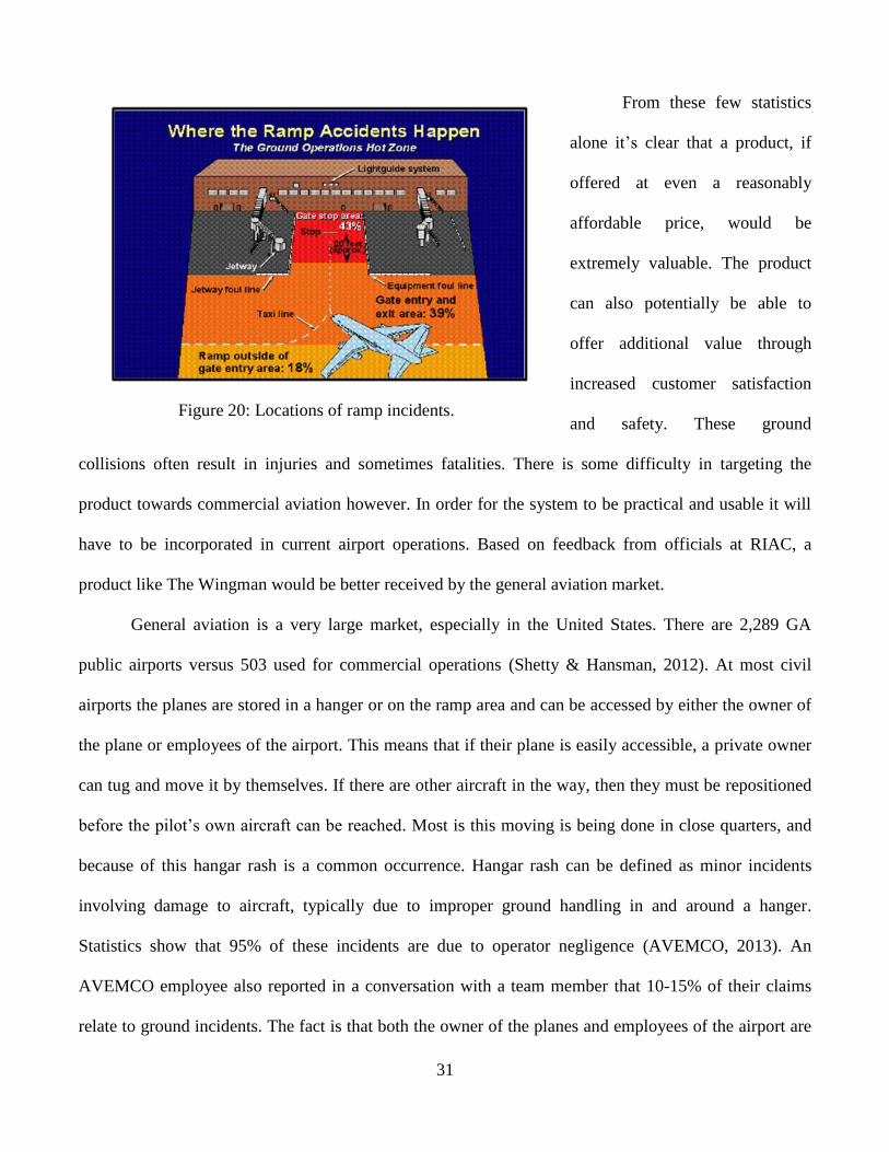
2013). Most of these incidents occur in close quarters in the gate stop area, as illustrated in Fig. 20.
31
Figure 20: Locations of ramp incidents.
From these few statistics
alone it’s clear that a product, if
offered at even a reasonably
affordable price, would be
extremely valuable. The product
can also potentially be able to
offer additional value through
increased customer satisfaction
and safety. These ground
collisions often result in injuries and sometimes fatalities. There is some difficulty in targeting the
product towards commercial aviation however. In order for the system to be practical and usable it will
have to be incorporated in current airport operations. Based on feedback from officials at RIAC, a
product like The Wingman would be better received by the general aviation market.
General aviation is a very large market, especially in the United States. There are 2,289 GA
public airports versus 503 used for commercial operations (Shetty & Hansman, 2012). At most civil
airports the planes are stored in a hanger or on the ramp area and can be accessed by either the owner of
the plane or employees of the airport. This means that if their plane is easily accessible, a private owner
can tug and move it by themselves. If there are other aircraft in the way, then they must be repositioned
before the pilot’s own aircraft can be reached. Most is this moving is being done in close quarters, and
because of this hangar rash is a common occurrence. Hangar rash can be defined as minor incidents
involving damage to aircraft, typically due to improper ground handling in and around a hanger.
Statistics show that 95% of these incidents are due to operator negligence (AVEMCO, 2013). An
AVEMCO employee also reported in a conversation with a team member that 10-15% of their claims
relate to ground incidents. The fact is that both the owner of the planes and employees of the airport are

32
operating and moving these aircraft. This offers the advantage of targeting both as potential customers.
When damage occurs, whoever is responsible must pay, and that could be either party. The costs of
repairs on these smaller planes are not inexpensive. The cost of damage done to the wing of a Cessna
172 is at least $10,000 once inspection, labor, and parts are taken into account. Given the frequency of
these events, a product like The Wingman that would help to eliminate unnecessary mishaps would be in
high demand.
The main reason there has yet to be an answer to this problem is that previously, the focus has
been on a permanently installed system into the aircraft, such as cameras or radar. This is why
portability and affordability were key considerations when conceptualizing and designing The
Wingman. In order to effectively penetrate this market the product would have to be highly adaptable
and portable. Based on feedback from meetings with the RIANG, incorporating the system into current
operations and ease of use were both of the upmost importance. Cost was also extremely important, as
an effective system that was seen as too costly would be in danger of simply not being used. In a more
commercial setting, The Wingman is not meant to replace wing walkers, but instead aid them as well as
tug operators in their operations. The Wingman is simultaneously inexpensive, easy to use, versatile and
easily integrated into current airport operations, which makes it highly marketable.
Much of the qualitative research on the problem took place at Quonset State Airport, observing
current operations and talking with official from RIAC and Quonset. Seeking further quantitative data to
aid in the design and market approach, the team drafted a survey to be issued to potential users. Two
surveys were generated; one tailored to private plane owners/pilots and one towards managers of fixed
base operators (FBO). There were 29 respondents to the pilot survey, and four to the FBO survey. Key
information such as functional needs, frequency of operations, and price points were all obtained from
the analysis of these surveys.

33
Figure 21: AOPA insurance quotes based on flight experience.
A high majority of respondents indicated that they would like to be alerted both visually and
audibly when they are 2-3 feet from an imminent collision. This was different from the 8-10 feet the
team had previously considered ideal. Overall interest from both pilots and FBOs was very encouraging.
The pilots also mostly indicated a willingness to pay at or above the current price, showing that the
device would actually be considered by real consumers, especially if insurance discounts were offered.
In order for the general aviation market to adapt this system they must perceive a clear benefit.
As mentioned before, the team obtained an estimate from Michael Kerwin, head of analytical
department at AVEMCO that an average wingtip repair cost $10,000. Further analysis of aviation
insurance indicated that a plane owner will pay anywhere from $400 to almost $1,800 a month for
insurance. Research in other industries showed that similar anti-collision systems built into cars save
drivers up to 20% off their premiums. Using this figure as an estimate, the monthly cost of aviation
insurance to what it could be if using The Wingman product was compared. In this comparison quotes
were included that factored in many variables such as plane type, coverage amount and pilot experience,
Fig. 21.
According to this data,
using The Wingman could
potentially save users from $100
to $400 per month. This means
that the product will pay for
itself in a short period of time.
In addition to these cost savings,
general aviation users can also
benefit greatly from a safety
viewpoint. Many times, minor
34
incidents could be overlooked or ignored, which can later lead to more severe problems or accidents.
This safety benefit outweighs any potential cost saving or increased convenience.
Wingtip collisions in hangar and taxi areas are an issue that has been lingering in the aviation
industry for some time. Especially in situations where a lone pilot or tug driver is moving a plane, there
is often a need for assistance in judging the distance to other nearby planes or hangar doors and walls.
The ability to use The Wingman in this situation allows the operator to move their plane safely. In larger
commercial situations where wing walkers are in use, accidents still occur even with extensive protocol
in place. Giving wing walkers additional equipment without the need to retrofit the plane is an ideal
middle-ground solution which enhances situational awareness without introducing costly weight to the
aircraft or distracting camera feeds.
The design solution shown here has been demonstrated as an effective tool in solving this
problem. The use of suction cups is a safe and effective way of temporarily attaching to a wingtip. This
is effective on many common plane geometries, and can be applied to the top or bottom of the wingtip.
The swivel mount also accounts for the surface of the wingtip not being parallel to the ground.
Ultrasonic sensors avoid any possible issues of interference with other airport communications, and are
an effective proximity detection method in a wide range of temperatures and conditions. The
combination of a visual and audio signal ensures that the user will be alerted to danger even if unable to
see the wingtip.
The design has been enthusiastically endorsed by the Rhode Island Airport Corporation officials
the team has been in contact with, and was improved by their feedback at multiple stages in the process.
The design team as a whole has full confidence that, if implemented into the industry, The Wingman
could play a role in ending wingtip collisions in hangar, taxi, and non-movement apron areas.

35
8 Appendices
Appendix A – Contact Information
Advisors
Bahram Nassersharif
214 Wales Hall
92 Upper College Rd.
Kingston, RI 02881
Phone: (401) 874-9335
Fax: (401) 874-2355
Carl-Ernst Rousseau
222-B Wales Hall
92 Upper College Rd.
Kingston, RI 02881
Phone: (401) 874-2542
Fax: (401) 874-2355
Valerie Maier-Speredelozzi
203 Wales Hall
92 Upper College Rd.
Kingston, RI 02881
Phone: (401) 874-5187
Fax: (401) 874-2355
Team Members
Christopher Clark
99 Jambray Avenue
Warwick, RI 02886
(401) 578-6824
Kyle DellaGrotta
11 Baneberry Drive
Cranston, RI 02921
(401) 222-0945
Lawrence Higgins
129 Ferry Landing Circle
Portsmouth, RI 02871
(860) 334-0326
David Powers
293 Harriet Lane
Cumberland, RI 02864
(401) 787-4044
Ronald Wheeler
120 Dogwood Dr Apt 102
West Warwick, RI 02893
(401) 578-5112
36
Appendix B – Description of University
University of Rhode Island
The University of Rhode Island, founded in 1892, is Rhode Island’s public, learner-centered
research university, holding accreditation from the New England Association of Schools and
Colleges (NEASC). It is the only public institution in the state offering undergraduate, graduate, and
professional students the distinctive educational opportunities of a major research university. The
main campus is on 1,200 acres in Kingston, Rhode Island with three satellite campuses: Feinstein
Providence Campus, Narragansett Bay Campus, and the W. Alton Jones Campus. As of this past fall,
there are 13,398 undergraduate students and 3,053 graduate students, of those students, 9,882 are in-
state residents and 6,569 are from out-of-state or international. There are over 80 majors offered at
the university from eight degree granting colleges: Arts and Sciences, Business Administration,
Continuing Education, Engineering, Environmental and Life Sciences, Human Science and Services,
Nursing, and Pharmacy.
College of Engineering
The College of Engineering at the University of Rhode Island has the vision to be “a global
leader in engineering education and research.” Their diverse community of scholars, students, and
professional staff is devoted to the development and application of advanced methods and
technologies. The college offers eight different engineering programs to its undergraduates:
Biomedical, Chemical, Civil, Computer, Electrical, Industrial and Systems, Mechanical, and Ocean.
The college, accredited by the Accreditation Board for Engineering and Technology (ABET)
educates all focuses to be creative problem solvers, innovators, inventors, and entrepreneurs and to
utilize those skills in the advancement of our society’s knowledge.

37
Appendix C – Non-University Partners
Rhode Island Airport Corporation
The Rhode Island Airport Corporation (RIAC) is a governmental agency and public
instrumentality of the state of Rhode Island which manages all publicly owned airports within
the state.
The corporation was formed in 1992 as a semiautonomous subsidiary of the Rhode Island
Port Authority, which has since become the Rhode Island Economic Development Corporation.
RIAC is responsible for the design, construction, operation, and maintenance of the six state-
owned airports, and for the supervision of all civil airports, landing areas, navigational facilities,
air schools, and flying clubs throughout the state. The six state-owned airports include T. F.
Green Airport, the state's commercial airport with scheduled air carrier service, and the general
aviation airports at Block Island, Newport, North Central, Quonset, and Westerly. RIAC is
governed by a seven-member board of directors.
Rhode Island Air National Guard
The 143d Airlift Wing provides worldwide combat airlift and combat support forces to
the nation, and to provide resources to protect life, property and public safety for Rhode Island
and the local community. 143d Airlift Wing leadership is recognized as amongst the most
aggressive, demanding and the best in the C-130 community. To remain viable for the present
and relevant in the future the Wing has aggressively pursued three avenues: base infrastructure
and modernization, C-130J-30 advancement and becoming the C-130 “airbridge” for the Air
Force.

38
Appendix D – Sign-off Form

39
Appendix E – Evaluation of Experience
Students
This competition provided a meaningful learning experience for the design team. Not
only did it allow the team to learn how to work together as a group but it also provided the
exciting experience of working directly with officials from the Rhode Island Airport
Corporation. The Team Captain served as an aircrew member for six years on board a Rhode
Island Air National Guard C-130J and has experience working with aircraft and the aviation
industry. Even for him, this was a new type of challenge. For the rest of the team, the
competition served as a thorough introduction to the industry. Furthermore, this project allowed
the team to work and interact in a professional environment. This was an excellent opportunity to
learn skills that will be useful for future careers.
The largest challenge in this competition was the concept generation process. The idea of
participating in this competition was very intriguing and the team was ready to try and make a
difference in the aviation community. After each teammate reviewed the competition guidelines,
an initial team meeting was held to discuss what was initially learned and the ideas that each
team member had come up with. Finding a suitable solution to a problem that was of interest to
RIAC and fit the needs of the multidisciplinary team took much valuable time. Upon researching
initial ideas, many concepts had already been created by other companies. Others were beyond
the team’s financial resources or the available time. Once the team decided to tackle the problem
of wingtip collisions, the remaining major difficulties were finding a suitable method of
detection, the best warning signal, and the overall system layout. The methods used to solve
these issues are described throughout this design report.
To develop the hypothesis of how this wingtip collision avoidance system would
function, the team investigated other technologies that solved similar design problems. For

40
example, many cars today use ultrasonic technology to warn drivers of an imminent collision
while backing up. It was hypothesized that this same technology could work for the aviation
industry. Suction cups designed to lift 40 pound floor tiles could also be used as a reliable
attachment mechanism for the system to the wingtip. A swivel mount from a camera tripod
serves as an effective leveling system, so the team decided it would also be suitable for The
Wingman. This research proved to be vital in developing the team’s hypothesis.
The participation of industry professionals during this process was very appropriate,
valuable, and meaningful. Several times when the team needed additional understanding or
insight, the Team Captain set up a meeting with RIAC to discuss team progress and seek
constructive criticism and guidance. For example, the addition of an audible alarm came directly
from interactions with RIAC and RIANG. The final geometry of the suction cup base also came
from interactions with the sponsor. Most importantly, sponsor interactions helped the team
realize that hangar rash and other wingtip related collisions remain a huge concern for many
members of the aviation industry.
The biggest lesson the team learned from this project was how to work together to solve a
major problem. It allowed the team to design, test, and analyze a product that has never before
been conceptualized or created. Going through the entire design process, including identifying a
need in the industry, gave all members of the team highly valuable experience. This project also
allowed the team to practice peer and professional collaboration. These skills, often
underemphasized in engineering education, will be very useful in the workforce.

41
Advisor
To: FAA Design Competition review panel
This is the fifth year that our university and engineering program participates in the FAA
design competition. I selected this competition as one of the projects for my senior capstone
design course in mechanical, industrial, and systems engineering because the program
description and particularly timeline was an excellent match for my project requirements. Our
senior capstone design sequence starts in the fall of the senior year and concludes in the
following spring semester.
The value of the educational experience for students participating is excellent. In
particular, interactions with our local Rhode Island Airport Corporation (RIAC) were
outstanding and we received tremendous support from the engineering staff there. The students
conducted a broad and comprehensive search through the problem space outlined by the FAA
design competition and identified a problem of significance to RIAC that is also of significant
interest nationally (and perhaps internationally).
The most significant challenge for the students at the beginning was to identify, define,
and research the problem(s) of interest. This search was conducted over a period of two months,
which delayed them somewhat during the fall semester. This delay was necessary because of the
broad scope definition of problems provided by the FAA design competition and the necessary
interaction time with the state airport corporation staff.
The student team has done an excellent job in thoroughly exploring their problem
(methods for mitigating and avoiding wingtip collision and damage). They have designed a
practical and very economical solution that does not require retrofits to the aircraft. They have
prototyped their solution and have obtained excellent results to pursue the creation of a
marketable product. Their survey of pilots, airport operators, and airport and airline executives

42
shows high interest in this product. We are in the process of applying for a provisional patent on
this design. This is exactly the type of process and experience that we expect for our students on
design projects.
I am very pleased with the competition process, project solicitation, and organization of
the FAA design competition. I will definitely use this competition again in the future if it will be
continued. If you have any questions or need additional information, please contact me.
Sincerely,
Bahram Nassersharif, Ph.D.
Distinguished University Professor

43
Appendix F – Reference List
AVEMCO. (2013, November 17). The Flight Isn't Over Until The Plane Is In The Hangar.
Retrieved from avemco.com: https://www.avemco.com/Information/Blogs/The-Flight-
Isn%E2%80%99t-Over-Until-the-Plane-is-in-the-Hangar.aspx
Broderick, S. (2013, October 5). NTSB's Aircraft Taxi-Assist Camera Recommendation Rejected
By FAA. Retrieved from Aviation Week:
http://www.aviationweek.com/Article.aspx?id=/article-xml/avd_03_29_2013_p02-02-
564029.xml.
FAA. (2007, February 28). Introduction to Safety Management Systems (SMS) for Airport
Operations. Retrieved from Advisory Circular:
http://www.faa.gov/documentLibrary/media/advisory_circular/150-5200-
37/150_5200_37.pdf
FAA. (2014). Design Competition Booklet. Retrieved from FAA Design Competition:
http://faadesigncompetition.odu.edu/Apps/FAAUDCA.nsf/2013_DesignComp_Booklet.p
df?OpenFileResource
FAA Regulations. (2013, April 14). Retrieved from faa.gov:
http://www.faa.gov/regulations_policies/faa_regulations/
Flightcom. (2013, November 20). Flightcom Corporation White Paper No. FL11-11.01.
Retrieved from Flightcom.net: http://www.flightcom.net/wp-
content/files/flight_whitepaper_final.pdf
Fun, S. (2013, October 24). Sealed LED RGB Strip. Retrieved from sparkfun.com:
https://www.sparkfun.com/products/12024

44
Infanger, J. F. (2011, September 8). Preventing Hangar Rash. Retrieved from
www.aviationpros.com: http://www.aviationpros.com/article/10346374/attacking-hangar-
rash
Longley, R. (2013, December 13). Pilots Blast NTSB on Cockpit Video Cameras. Retrieved from
About.com: http://usgovinfo.about.com/od/technologyandresearch/a/cockpitcams.htm
Maxbotix. (2013, October 4). MB 7363 Data Sheet. Retrieved from Maxbotix.com:
http://www.maxbotix.com/documents/HRXL-MaxSonar-WR_Datasheet.pdf
Maxbotix. (2013, October 10). MB7363 Ultrasonic Sensor. Retrieved from maxbotix.com:
http://www.maxbotix.com/.
Maxbotix. (2013, October 4). Mounting Harware. Retrieved from maxbotix.com:
http://www.maxbotix.com/Ultrasonic_Sensors/MB7950.htm
McFadden, K. (2014, February 28). Two Quantas Airways Jets Hit Each Other on Runway at
LAX. Retrieved from Travelers Today:
http://www.travelerstoday.com/articles/8972/20140228/two-qantas-airways-jets-hit-each-
other-on-runway-at-lax.htm
Murphy, D. (2007). City of Phoenix Aviation Department Rules and Regulations. Phoenix.
NIOSH. (2009, June). NIOSH Lifting Equation. Retrieved from ttl.fi:
http://www.ttl.fi/en/ergonomics/methods/workload_exposure_methods/table_and_metho
ds/Documents/NioshLiftingEquqtion.pdf
Pelican. (2013, October 17). 1730 Transport Case. Retrieved from pelican.com/cases:
http://www.pelican.com/cases_detail.php?Case=1730
Railhead Corportation. (2, December 2013). WingWalker. Retrieved from
wingwalkersafety.com: http://wingwalkersafety.com/.

45
Shetty, K. I., & Hansman, R. J. (2012, August). Current and Histroical Trends in General
Aviation in the United States. Retrieved from dspace.mit.edu:
http://dspace.mit.edu/bitstream/handle/1721.1/72392/ICAT%20REPORT%20SHETTY.p
df
Spruce, A. (2014, February 4). Remove Before Flight Streamer. Retrieved from
aircraftspruce.com:
http://www.aircraftspruce.com/catalog/pspages/removestreamer.php?clickkey=4499
Suction Cups. (2013, November 15). Retrieved from McMaster-Carr:
http://www.mcmaster.com/#standard-suction-cups/=pqny8s
Trinity College. (7, October 2013). WingWatch: Aircraft Ground Collision Avoidance System.
Retrieved from Trinity College Dublin:
https://www.scss.tcd.ie/Gerard.Lacey/Gerard_Lacey_Homepage/WingWatch_files/Wing
Watch%20Overview.pdf
U.S Patent #6,118,401. (2013, November 21). Retrieved from United States Patent and
Trademark Office: http://patft.uspto.gov/netacgi/nph-
Parser?Sect1=PTO1&Sect2=HITOFF&d=PALL&p=1&u=%2Fnetahtml%2FPTO%2Fsrc
hnum.htm&r=1&f=G&l=50&s1=6,118,401.PN.&OS=PN/6,118,401&RS=PN/6,118,401.
U.S. Patent #4,139,848. (2013, November 21). Retrieved from United States Patent and
Trademark Office: http://patft.uspto.gov/netacgi/nph-
Parser?Sect1=PTO1&Sect2=HITOFF&d=PALL&p=1&u=%2Fnetahtml%2FPTO%2Fsrc
hnum.htm&r=1&f=G&l=50&s1=4,139,848.PN.&OS=PN/4,139,848&RS=PN/4,139,848
U.S. Patent #7,379,165. (2013, November 21). Retrieved from United States Patent and
Trademark Office: http://patft.uspto.gov/netacgi/nph-

46
Parser?Sect1=PTO1&Sect2=HITOFF&d=PALL&p=1&u=%2Fnetahtml%2FPTO%2Fsrc
hnum.htm&r=1&f=G&l=50&s1=7,379,165.PN.&OS=PN/7,379,165&RS=PN/7,379,165
Vandel, B. (2004). Equipment Damage and Human Injury on the Apron: Is it a cost of doing
business? Retrieved from asasi.org:
http://asasi.org/papers/2004/Vandel_Ramp%20Damage_ISASI04.pdf
WCVB. (2014, February 18). Plane hits parked deicing truck at Logan. Retrieved from
WCVB.com: http://www.wcvb.com/news/plane-hits-parked-deicing-truck-at-
logan/24545758#!DDwAl
YesComUSA. (2014, January 15). Swivel Mount. Retrieved from yescomusa.com:
http://www.yescomusa.com/Swivel-Tripod-BallHead-Quick-Release-Plate-w-Ball-
Head.html