cover sel language - walla walla universityralph.stirling/classes/engr480/docs/... · sel language...
TRANSCRIPT

Intelligent Actuator Inc.
DS-S-C1
Super SEL Type E
Programming Manual
Super SEL Type E
SEL LANGUAGE

This publication was written to assist you in better understanding this part of your IA system. If you require further assistance, pleasecontact IA Technical Support. For Central and East Coast Time Zones, please call our Itasca, IL office at 1-800-944-0333 or FAX 630-467-9912. For Mountain and Pacific Time Zones, please call our Torrance, CA office at 1-800-736-1712 or FAX 310-891-0815; Mondaythru Friday from 8:30AM to 5:00PM.
Intelligent Actuator, Inc.U.S. Headquarters2690 W. 237th StreetTorrance, CA 90505310-891-6015 / 310-891-0815 FAX
Intelligent Actuator, Inc.Midwest Regional Office1261 Hamilton ParkwayItasca, IL 60143630-467-9900 / 630-467-9912 FAX
www.intelligentactuator.com
©April, 1998 Intelligent Actuator, Inc. All rights reserved.No portion of this publication may be reproduced, stored in a retrieval system, or transmitted, in any form or by any means, electronic, mechnical,recording, or otherwise, without the prior written permission of Intelligent Actuator, Inc.
DisclaimerThe information and technical data contained herein are subject to change without notice. Intelligent Actuator, Inc. assumes no responsibility for anyerrors or omissions regarding the accuracy of the information contained in this publication.

1
Foreword
*1 An interpreter is executing a command as it translates that command into computer language.
SEL Language is the simplest type of the numerous robot languages being used today. The perplexing problem ofusing simple language to effect high level control has been beautifully resolved with SEL Language.
The language most generally used for robot control is based on BASIC language which uses sentences formats andinterpreting these sentences requires considerable time. As the level of expression gets higher, the interpreterbecomes less capable of handling real time control *1. At this point, an extra step, compling *2 , needs to beadded. Furthermore, the process becomes increasingly complex, as one encounters problems with false commands,required knowledge of MS-DOS, etc.
It goes without saying that being able to accomplish the same task using a simple method is much better. So,we welcome you to step into the world of high level control using SEL Language which is a simple system, thatoperates at high speeds even as it is interpreting.
*2 Compling refers to translating the command into computer language before the comand is executed,
2
Table of Contents
1. Numerals and Symbols in SEL Language1.1 List of numerals handled by SEL Language ........................................................................................................ 41.2 Symbols used in SEL Language .......................................................................................................................... 5
2. I/O Ports2.1 Input ports .......................................................................................................................................................... 62.2 Output ports ........................................................................................................................................................ 62.3 List of I/O ports for the Super SEL type .............................................................................................................. 72.4 List of I/O ports for the DS type .......................................................................................................................... 8
3. Flags ......................................................................................................................................................................... 10
4. Variables4.1 What are variables? ........................................................................................................................................... 114.2 Types of variables ............................................................................................................................................. 11
5. Tags .......................................................................................................................................................................... 14
6. Subroutines ...............................................................................................................................................................15
7. Axis Designation7.1 Axis No. and Display ..........................................................................................................................................167.2 Axis pattern. .......................................................................................................................................................17
8. Structure of SEL Language8. 1 Position program. ...............................................................................................................................................188. 2 Commands ........................................................................................................................................................ 19
8.2-1 Structure of SEL Language ..................................................................................................................... 198.2-2 Expansion Condition ............................................................................................................................... 20
9. List of Parameters9.1 Common parameters for multiple axes. ...............................................................................................................229.2 Common parameters for a single axis. .................................................................................................................239.3 Parameters by axis ..............................................................................................................................................24
10. List of SEL Language Command Codes by Function ................................................................................................26
11. List of SEL Language Command Codes in Alphabetical Order .................................................................................30
3
Table of Contents
12. SEL Language12.1 Numeric calculation commands .......................................................................................................................3212.2 Arithmatic calculation commands ....................................................................................................................3412.3 Functional calculation commands ...................................................................................................................3712.4 Logic operation commands ..............................................................................................................................4012.5 Comparison operation commands ...................................................................................................................4312.6 Timer commands ..............................................................................................................................................4412.7 I/O•Flag operation commands .........................................................................................................................4612.8 Program control commands .............................................................................................................................5212.9 Task management commands ..........................................................................................................................5412.10 Resource management commands ...................................................................................................................5812.11 Postion operation commands ..........................................................................................................................5912.12 Actuator control declarations ..........................................................................................................................6412.13 Actuator control commands ............................................................................................................................7212.14 Structured IF commands. .................................................................................................................................8012.15 Structured DO commands ................................................................................................................................8312.16 Branching commands ......................................................................................................................................8512.17 External I/O commands ....................................................................................................................................8912.18 String processing commands ...........................................................................................................................92
13. Error Codes13.1 List of Error Codes ..........................................................................................................................................9813.2 What to do when an Error Code occurs ...........................................................................................................99
4
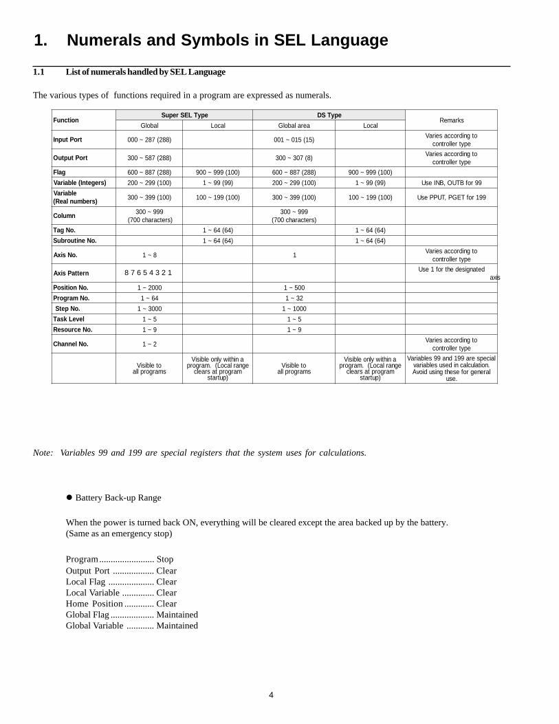
Battery Back-up Range
When the power is turned back ON, everything will be cleared except the area backed up by the battery.(Same as an emergency stop)
Program........................ StopOutput Port .................. ClearLocal Flag .................... ClearLocal Variable .............. ClearHome Position ............. ClearGlobal Flag ................... MaintainedGlobal Variable ............ Maintained
noitcnuFepyTLESrepuS epyTSD
skrameRlabolG lacoL aeralabolG lacoL
troPtupnI )882(782~000 )51(510~100otgnidroccaseiraV
epytrellortnoc
troPtuptuO )882(785~003 )8(703~003otgnidroccaseiraV
epytrellortnoc
galF )882(788~006 )001(999~009 )882(788~006 )001(999~009
)sregetnI(elbairaV )001(992~002 )99(99~1 )001(992~002 )99(99~1 99rofBTUO,BNIesU
elbairaV)srebmunlaeR( )001(993~003 )001(991~001 )001(993~003 )001(991~001 991rofTEGP,TUPPesU
nmuloC 999~003)sretcarahc007(
999~003)sretcarahc007(
.oNgaT )46(46~1 )46(46~1
.oNenituorbuS )46(46~1 )46(46~1
.oNsixA 8~1 1otgnidroccaseiraV
epytrellortnoc
nrettaPsixA stigidyranib8detangisedehtrof1esU
sixa
.oNnoitisoP 0002~1 005~1
.oNmargorP 46~1 23~1
.oNpetS 0003~1 0001~1
leveLksaT 5~1 5~1
.oNecruoseR 9~1 9~1
.oNlennahC 2~1otgnidroccaseiraV
epytrellortnoc
otelbisiVsmargorplla
anihtiwylnoelbisiVegnarlacoL(.margorp
margorptasraelc)putrats
otelbisiVsmargorplla
anihtiwylnoelbisiVegnarlacoL(.margorp
margorptasraelc)putrats
laicepsera991dna99selbairaV.noitaluclacnidesuselbairavlarenegrofesehtgnisudiovA
.esu
1.1 List of numerals handled by SEL Language
Note: Variables 99 and 199 are special registers that the system uses for calculations.
1. Numerals and Symbols in SEL Language
The various types of functions required in a program are expressed as numerals.
8 7 6 5 4 3 2 1
5
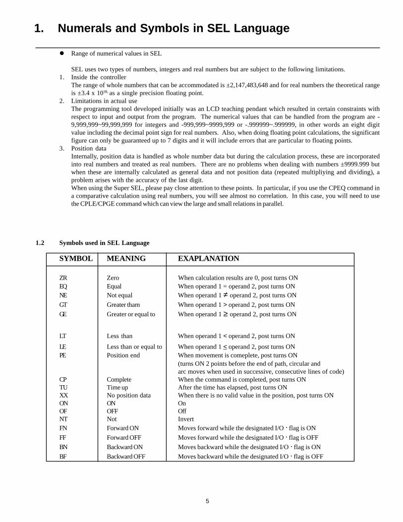
Range of numerical values in SEL
SEL uses two types of numbers, integers and real numbers but are subject to the following limitations.1. Inside the controller
The range of whole numbers that can be accommodated is ±2,147,483,648 and for real numbers the theoretical rangeis ±3.4 x 1038, as a single precision floating point.
2. Limitations in actual useThe programming tool developed initially was an LCD teaching pendant which resulted in certain constraints withrespect to input and output from the program. The numerical values that can be handled from the program are -9,999,999~99,999,999 for integers and -999,999~9999,999 or -.999999~.999999, in other words an eight digitvalue including the decimal point sign for real numbers. Also, when doing floating point calculations, the significantfigure can only be guaranteed up to 7 digits and it will include errors that are particular to floating points.
3. Position dataInternally, position data is handled as whole number data but during the calculation process, these are incorporatedinto real numbers and treated as real numbers. There are no problems when dealing with numbers ±9999.999 butwhen these are internally calculated as general data and not position data (repeated multipliying and dividing), aproblem arises with the accuracy of the last digit.When using the Super SEL, please pay close attention to these points. In particular, if you use the CPEQ command ina comparative calculation using real numbers, you will see almost no correlation. In this case, you will need to usethe CPLE/CPGE command which can view the large and small relations in parallel.
1.2 Symbols used in SEL Language
1. Numerals and Symbols in SEL Language
SYMBOL MEANING EXAPLANATION
ZR Zero When calculation results are 0, post turns ONEQ Equal When operand 1 = operand 2, post turns ONNE Not equal When operand 1 ≠ operand 2, post turns ON
GT Greater tham When operand 1 > operand 2, post turns ON
GE Greater or equal to When operand 1 ≥ operand 2, post turns ON
LT Less than When operand 1 < operand 2, post turns ON
LE Less than or equal to When operand 1 < operand 2, post turns ONPE Position end When movement is comeplete, post turns ON
(turns ON 2 points before the end of path, circular andarc moves when used in successive, consecutive lines of code)
CP Complete When the command is completed, post turns ONTU Time up After the time has elapsed, post turns ONXX No position data When there is no valid value in the position, post turns ONON ON OnOF OFF OffNT Not InvertFN Forward ON Moves forward while the designated I/O · flag is ON
FF Forward OFF Moves forward while the designated I/O · flag is OFF
BN Backward ON Moves backward while the designated I/O · flag is ON
BF Backward OFF Moves backward while the designated I/O · flag is OFF
6
.oNtupnItnemngissA
G·EepyT
320~100 dradnatS
740~420 noitpO
170~840 noitpO
590~270 noitpO
.oNtuptuOtnemngissA
G·EepyT
323~003 dradnatS
743~423 noitpO
173~843 noitpO
593~273 noitpO
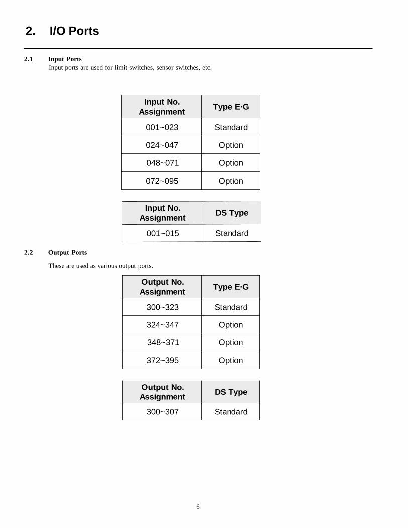
2.1 Input PortsInput ports are used for limit switches, sensor switches, etc.
.oNtupnItnemngissA
epyTSD
510~100 dradnatS
2.2 Output Ports
These are used as various output ports.
.oNtuptuOtnemngissA
epyTSD
703~003 dradnatS
2. I/O Ports
7
.oNtroP noitcnuF noitanalpxE
000 tupnitratSlanretxE .detucexesimargorpdetangisedeht,NOsnruttupnitnemomehttA
100 tupniresU .esoohcyehtsatropsihtesunacsresU
200 tupnitcatnocepyt-bpotsycnegremE .potsycnegremeotniseogrellortnoceht,FFOsnruttupnisihtnehW
300 evresermetsyS .)erutufehtninoitcnufwenaddaotdesueblliwtropsiht(desuebtonnaC
400 evresermetsyS .)erutufehtninoitcnufwenaddaotdesueblliwtropsiht(desuebtonnaC
500 tupniresU .esoohcyehtsatropsihtesunacsresU
600 tupniresU .esoohcyehtsatropsihtesunacsresU
700 tupniresU .esoohcyehtsatropsihtesunacsresU
800 )tupniresu(10.oNGRP
900 )tupniresu(20.oNGRP
010 )tupniresu(40.oNGRP
110 )tupniresu(80.oNGRP
210 )tupniresu(01.oNGRP
310 )tupniresu(02.oNGRP
410 )tupniresu(04.oNGRP
510
320tupniresU .esoohcyehtsatuptuosihtesunacsresU
420
782tupninoisnapxE
O/InoisnapxenanogniddaybdesuebnactahtstroptupniresueraesehT.tinutroptupnideepshgihrotinudrac
003 tuptuomralA/potsycnegremE .sruccororrenanehwropotsycnegremenagnirudNOsnrutsihT
103 tuptuoydaeR .ydaersirellortnocehtnehwNOsnrutsihT
203
323tuptuoresU .esoohcyehtsatuptuosihtesunacsresU
423
785tuptuonoisnapxE
O/InoisnapxenanogniddaybdesuebnactahttroptuptuoresueraesehT.tinudrac
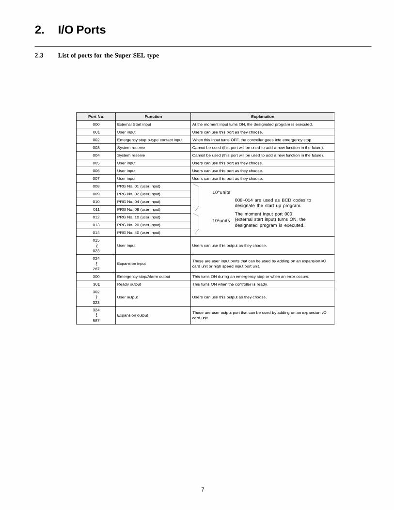
2.3 List of ports for the Super SEL type
008~014 are used as BCD codes todesignate the start up program.
The moment input port 000(external start input) turns ON, thedesignated program is executed.
10°units
101units
2. I/O Ports
~~
~~
8
Program Mode.oNtroP noitcnuF noitanalpxE
)tupniresu(10.oNGRP
)tupniresu(20.oNGRP
)tupniresu(40.oNGRP
)tupniresu(80.oNGRP
)tupniresu(01.oNGRP
)tupniresu(02.oNGRP
evreseR
tupniteserUPC .rellortnocehtstratseR
000 tupnitratslanretxE .detucexesimargorpdetangisedeht,NOsnruttupnitnemomehttA
100
510tupniresU .esoohcyehtsatropsihtesunacsresU
003 tuptuomralA/potsycnegremE .sruccororrenanehwropotsycnegremenagnirudNOsnrutsihT
103 tuptuoydaeR .ydaersirellortnocehtnehwNOsnrutsihT
203
703tuptuoresU .esoohcyehtsatropsihtesunacsresU
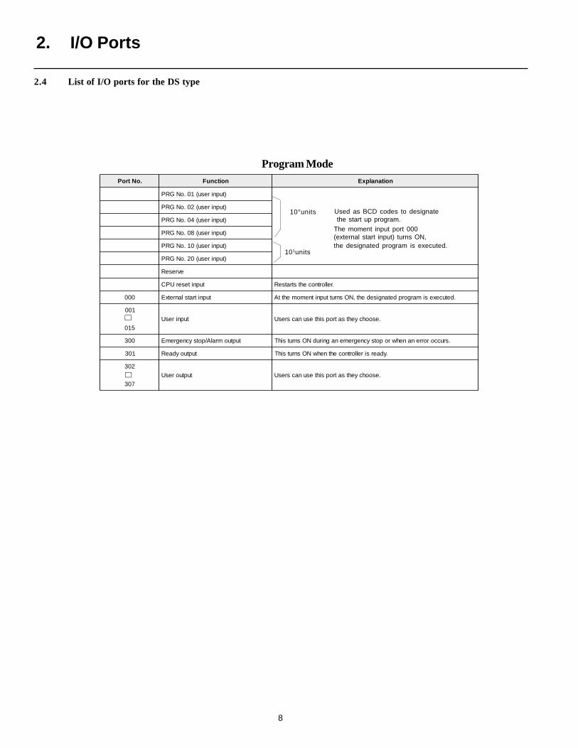
2.4 List of I/O ports for the DS type
Used as BCD codes to designate the start up program.
The moment input port 000(external start input) turns ON,the designated program is executed.
10°units
101units
∼∼
2. I/O Ports
9
.oNtroP noitcnuF noitanalpxE
)tupniresu(10.oNGRP
margorPehtnrut,edomgninoitisopehtgnisunehW.sutats)FFO(]0[ottupni.oN
)tupniresu(20.oNGRP
)tupniresu(40.oNGRP
)tupniresu(80.oNGRP
)tupniresu(01.oNGRP
)tupniresu(02.oNGRP
evreseR
tupniteserUPC .rellortnocehtstratseR
000 tupnitratslanretxE .detucexesimargorpdetangisedeht,NOsnruttupnitnemomehttA
100 tupnidloH .noitisopdetanisedehtotsevomrotautcaeht,NOsnrutsihtnehW
200
300CN .edomgninoitisopgnirudCNotsegnahc300~200
400 tupni1.oNnoitisoP
500 tupni2.oNnoitisoP
600 tupni4.oNnoitisoP
700 tupni8.oNnoitisoP
800 tupni01.oNnoitisoP
900 tupni02.oNnoitisoP
010 tupni04.oNnoitisoP
110 tupni08.oNnoitisoP
210 tupni001.oNnoitisoP
310 tupni002.oNnotisoP
410 tupni004.oNnoitisoP
510 CN .edomgninoitisopgnirudCNotsegnahc510
003 tuptuomralA/potsycnegremE .sruccororrenanehwropotsycnegremenagnirudNOsnrutsihT
103 tuptuoydaeR .ydaersirellortnocehtnehwNOsnrutsihT
203 tuptuoetelpmocgninoitisoP .etelpmocsievomnoitisopnehwNOsnrutsihT
303
703CN .edomgnirudCNotsegnahc703~303
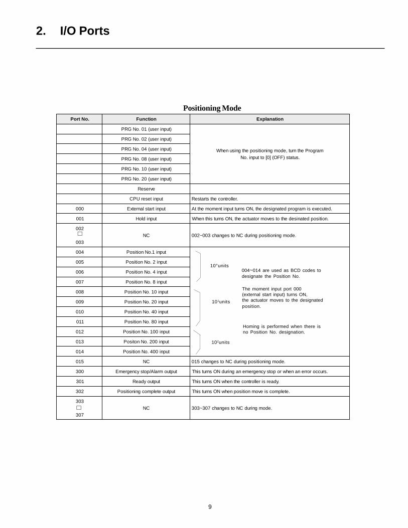
004~014 are used as BCD codes todesignate the Position No.
The moment input port 000(external start input) turns ON,the actuator moves to the designatedposition.
10°units
102units
101units
Homing is performed when there isno Position No. designation.
∼∼
2. I/O Ports
Positioning Mode

10
3. Flags
The function of flags is to set and reset data within "Memory." This is analogous to "internal relays" or "coils" in a PLC.
In general, there are two (2) types of flags: Global flags 600 ~ 887 which can be used in all programs and local flags 900 ~ 999 whichcan be used only in individual programs.
Global flags are saved when the power is turned OFF (battery backup). Local flags are erased when the power is turned OFF.
Program 1 Program n
WTON 600
Communicates signals by using global flagswhich are visible in allprograms.
Turn Flag 600 ON Waiting for Flag 600 to turn ON
Even though these are the samecommand, these local flags existindividually in each program.
BTON 900 BTON 900
BTON 600
3. Flags
rebmuNgalF 788~006 smargorpllanidesuebnaC:galflabolG
rebmuNgalF 999~009 margorplaudividninanihtiwylnodesuebnaC:galflacoL
11
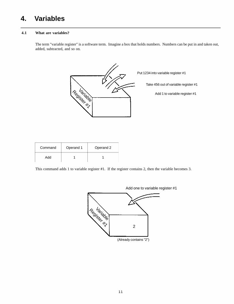
Command Operand 1 Operand 2
Add 1 1
This command adds 1 to variable register #1. If the register contains 2, then the variable becomes 3.
Add one to variable register #1
(Already contains "2")
Add 1 to variable register #1
Put 1234 into variable register #1
Take 456 out of variable register #1
4.1 What are variables?
The term "variable register" is a software term. Imagine a box that holds numbers. Numbers can be put in and taken out,added, subtracted, and so on.
Variable
Register #1
Variable
Register #12
4. Variables
12
Integer VariableRegister
Real VariableRegister
4. Variables
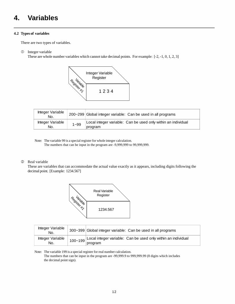
Note: The variable 99 is a special register for whole integer calculation.The numbers that can be input in the program are -9,999,999 to 99,999,999.
4.2 Types of variables
There are two types of variables.
Integer variableThese are whole number variables which cannot take decimal points. For example: [-2, -1, 0, 1, 2, 3]
1 2 3 4
Variable
Register #1
Real variableThese are variables that can accommodate the actual value exactly as it appears, including digits following thedecimal point. [Example: 1234.567]
1234.567
Variable
Register #1
Note: The variable 199 is a special register for real number calculation.The numbers that can be input in the program are -99,999.9 to 999,999.99 (8 digits which includesthe decimal point sign).
Integer VariableNo.
200~299 Global integer variable: Can be used in all programs
Integer VariableNo.
1~99Local integer variable: Can be used only within an individualprogram
Integer VariableNo.
300~399 Global integer variable: Can be used in all programs
Integer VariableNo.
100~199Local integer variable: Can be used only within an individualprogram
13
1234
4. Variables
Command Operand 1 Operand 2
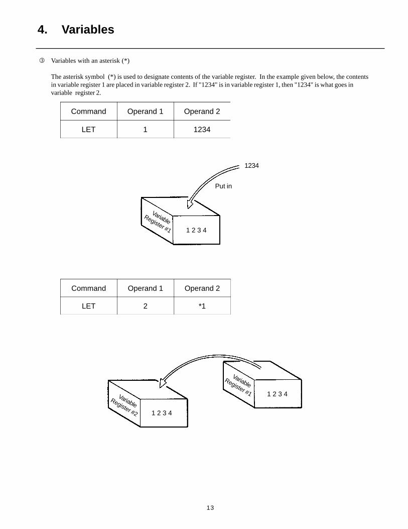
LET 1 1234
Command Operand 1 Operand 2
LET 2 *1
Variables with an asterisk (*)
The asterisk symbol (*) is used to designate contents of the variable register. In the example given below, the contentsin variable register 1 are placed in variable register 2. If "1234" is in variable register 1, then "1234" is what goes invariable register 2.
Put in
1 2 3 4
VariableRegister #1
VariableRegister #1Variable
Register #2 1 2 3 4
1 2 3 4
14
TAG 1
GOTO 1
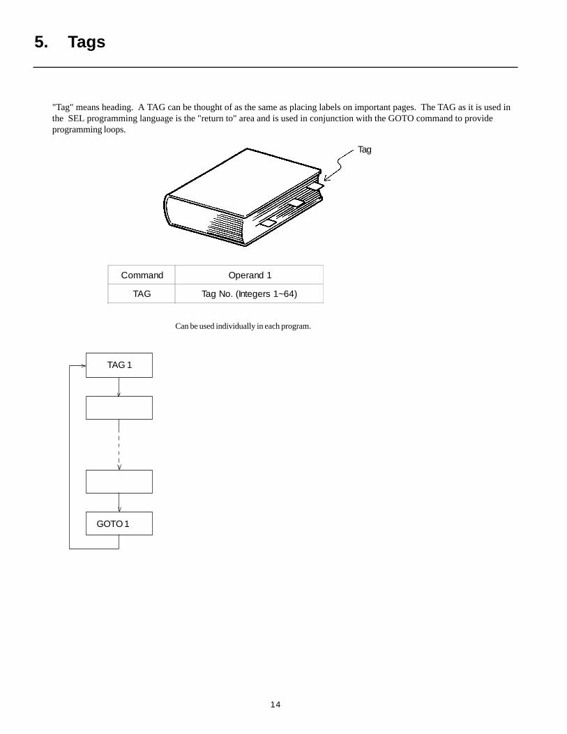
Can be used individually in each program.
Tag
5. Tags
"Tag" means heading. A TAG can be thought of as the same as placing labels on important pages. The TAG as it is used inthe SEL programming language is the "return to" area and is used in conjunction with the GOTO command to provideprogramming loops.
Command Operand 1
TAG Tag No. (Integers 1~64)
15
EXSR 1
EXSR 1
EXSR 1
BGSR 1
EDSR
Subroutine
Call subroutine
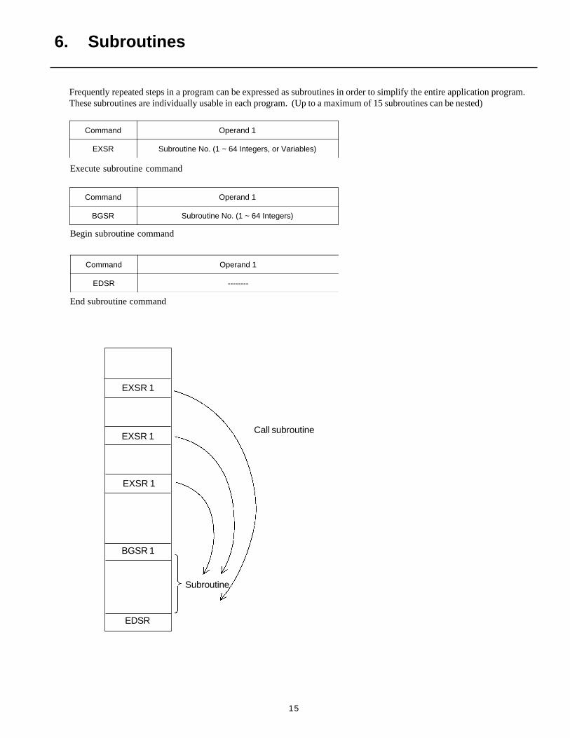
Frequently repeated steps in a program can be expressed as subroutines in order to simplify the entire application program.These subroutines are individually usable in each program. (Up to a maximum of 15 subroutines can be nested)
6. Subroutines
Execute subroutine command
Command Operand 1
BGSR Subroutine No. (1 ~ 64 Integers)
Begin subroutine command
Command Operand 1
EDSR --------
End subroutine command
Command Operand 1
EXSR Subroutine No. (1 ~ 64 Integers, or Variables)
16
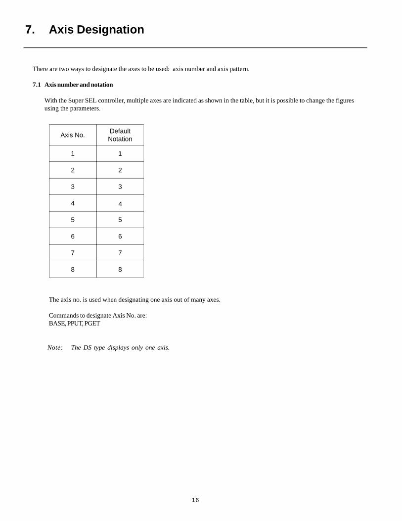
There are two ways to designate the axes to be used: axis number and axis pattern.
7.1 Axis number and notation
With the Super SEL controller, multiple axes are indicated as shown in the table, but it is possible to change the figuresusing the parameters.
7. Axis Designation
Axis No.DefaultNotation
1 1
2 2
3 3
4 4
5 5
6 6
7 7
8 8
The axis no. is used when designating one axis out of many axes.
Commands to designate Axis No. are:BASE, PPUT, PGET
Note: The DS type displays only one axis.
17
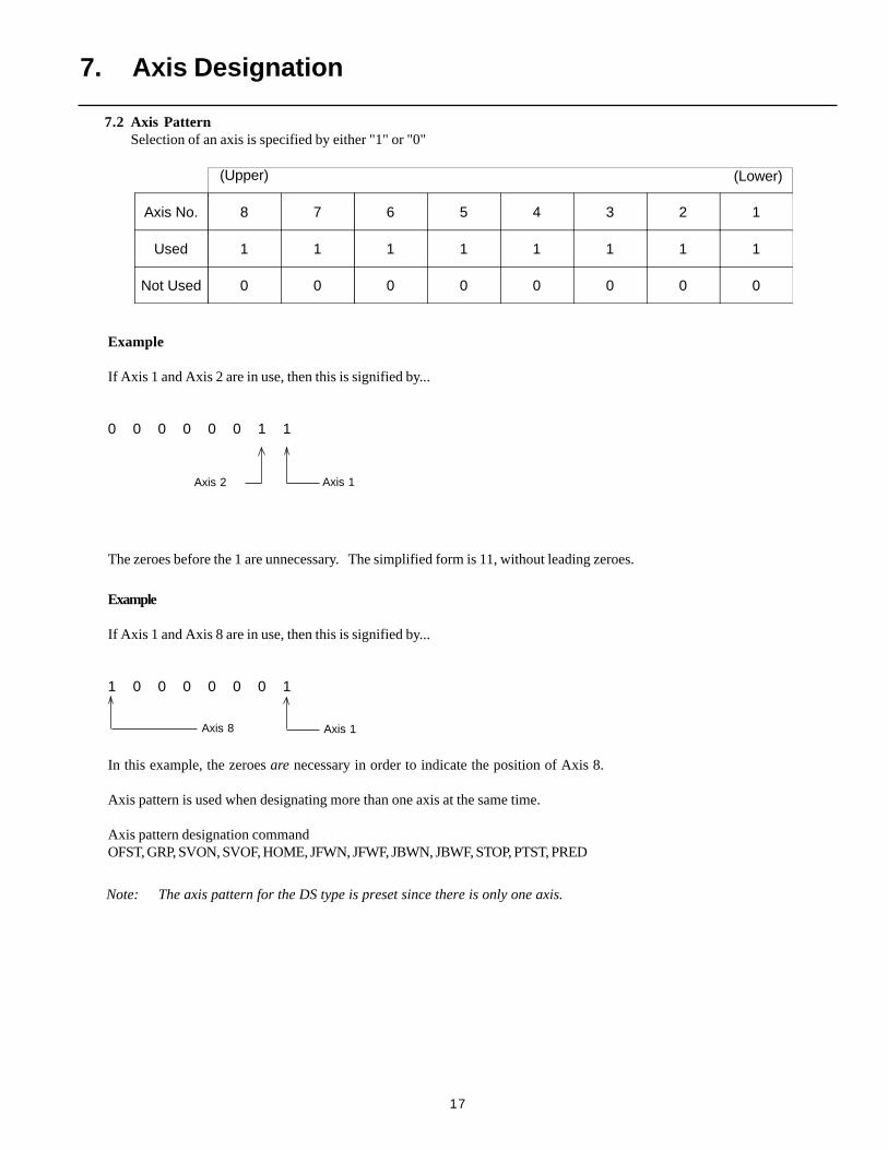
7.2 Axis PatternSelection of an axis is specified by either "1" or "0"
Axis No. 8 7 6 5 4 3 2 1
Used 1 1 1 1 1 1 1 1
Not Used 0 0 0 0 0 0 0 0
Example
If Axis 1 and Axis 8 are in use, then this is signified by...
1 0 0 0 0 0 0 1
The zeroes before the 1 are unnecessary. The simplified form is 11, without leading zeroes.
In this example, the zeroes are necessary in order to indicate the position of Axis 8.
Axis pattern is used when designating more than one axis at the same time.
Axis pattern designation commandOFST, GRP, SVON, SVOF, HOME, JFWN, JFWF, JBWN, JBWF, STOP, PTST, PRED
Axis 8 Axis 1
Axis 2 Axis 1
Example
If Axis 1 and Axis 2 are in use, then this is signified by...
0 0 0 0 0 0 1 1
7. Axis Designation
(Upper) (Lower)
Note: The axis pattern for the DS type is preset since there is only one axis.
18
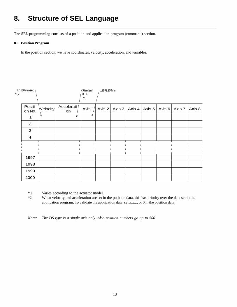
1~1500 mm/sec Standard0.3G
±9999.999mm
The SEL programming consists of a position and application program (command) section.
8.1 Position Program
In the position section, we have coordinates, velocity, acceleration, and variables.
8. Structure of SEL Language
-itisoP.oNno
yticoleV-itareleccA
no1sixA 2sixA 3sixA 4sixA 5sixA 6sixA 7sixA 8sixA
1
2
3
4
7991
8991
9991
0002
*1 Varies according to the actuator model.*2 When velocity and acceleration are set in the position data, this has priority over the data set in the
application program. To validate the application data, set x.xxx or 0 in the position data.
*1,2 *2
Note: The DS type is a single axis only. Also position numbers go up to 500.
19
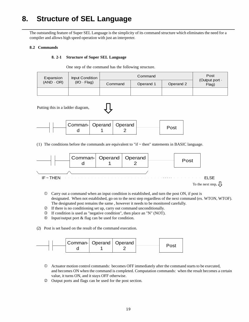
Carry out a command when an input condition is established, and turn the post ON, if post isdesignated. When not established, go on to the next step regardless of the next command (ex. WTON, WTOF).The designated post remains the same , however it needs to be monitored carefully.
If there is no conditioning set up, carry out command unconditionally. If condition is used as "negative condition", then place an "N" (NOT). Input/output port & flag can be used for condition.
Actuator motion control commands: becomes OFF immediately after the command starts to be executed,and becomes ON when the command is completed. Computation commands: when the result becomes a certainvalue, it turns ON, and it stays OFF otherwise.
Output ports and flags can be used for the post section.
(1) The conditions before the commands are equivalent to "if ~ then" statements in BASIC language.
Putting this in a ladder diagram,
The outstanding feature of Super SEL Language is the simplicity of its command structure which eliminates the need for acompiler and allows high speed operation with just an interpreter.
8.2 Commands
8. 2-1 Structure of Super SEL Language
One step of the command has the following structure.
noisnapxE)RO·DNA(
noitidnoCtupnI)galF·O/I(
dnammoC tsoP·troptuptuO(
)galFdnammoC 1dnarepO 2dnarepO
-nammoCd
dnarepO1
dnarepO2
tsoP
(2) Post is set based on the result of the command execution.
-nammoCd
dnarepO1
dnarepO2
tsoP
IF ~ THEN ELSE
-nammoCd
dnarepO1
dnarepO2
tsoP
To the next step,
8. Structure of SEL Language
. . . . .
20
OR
AND
AND
OR Expansion
AND/OR Expansion
Cond 1
Cond 2
Cond 3
Cond 1
Cond 2
Cond 1
Cond 2
Cond 3
AND
OR
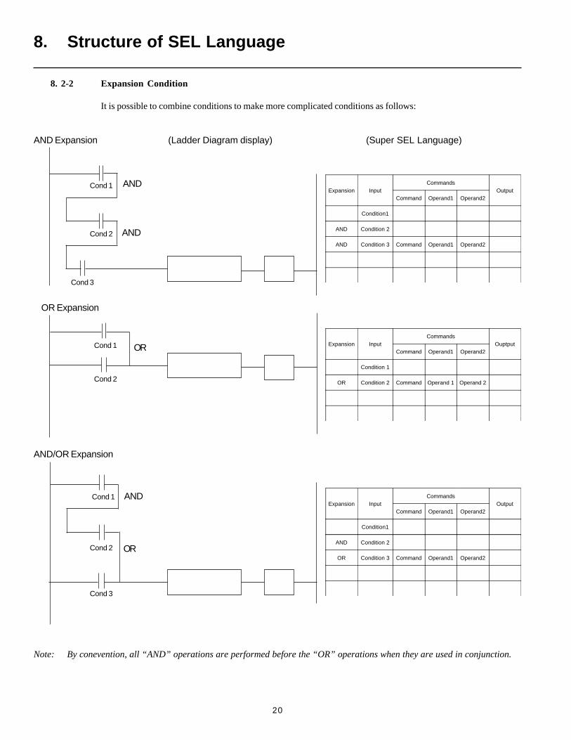
8. 2-2 Expansion Condition
It is possible to combine conditions to make more complicated conditions as follows:
8. Structure of SEL Language
Expansion InputCommands
OuptputCommand Operand1 Operand2
Condition 1
OR Condition 2 Command Operand 1 Operand 2
Expansion InputCommands
OutputCommand Operand1 Operand2
Condition1
AND Condition 2
OR Condition 3 Command Operand1 Operand2
AND Expansion (Ladder Diagram display) (Super SEL Language)
Expansion InputCommands
OutputCommand Operand1 Operand2
Condition1
AND Condition 2
AND Condition 3 Command Operand1 Operand2
Note: By conevention, all “AND” operations are performed before the “OR” operations when they are used in conjunction.
21
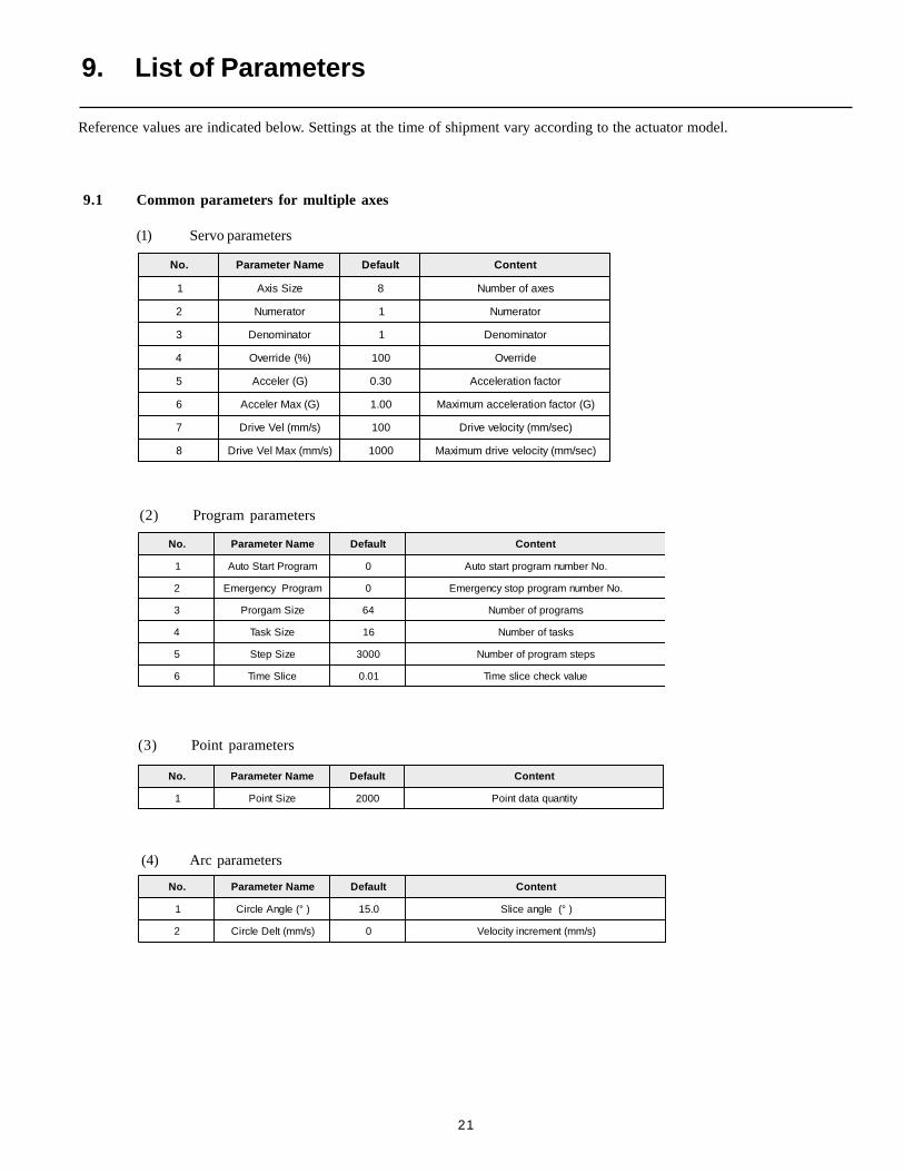
9.1 Common parameters for multiple axes
(1) Servo parameters
.oN emaNretemaraP tluafeD tnetnoC
1 eziSsixA 8 sexaforebmuN
2 rotaremuN 1 rotaremuN
3 rotanimoneD 1 rotanimoneD
4 )%(edirrevO 001 edirrevO
5 )G(releccA 03.0 rotcafnoitareleccA
6 )G(xaMreleccA 00.1 )G(rotcafnoitareleccamumixaM
7 )s/mm(leVevirD 001 )ces/mm(yticolevevirD
8 )s/mm(xaMleVevirD 0001 )ces/mm(yticolevevirdmumixaM
.oN emaNretemaraP tluafeD tnetnoC
1 margorPtratSotuA 0 .oNrebmunmargorptratsotuA
2 margorPycnegremE 0 .oNrebmunmargorppotsycnegremE
3 eziSmagrorP 46 smargorpforebmuN
4 eziSksaT 61 sksatforebmuN
5 eziSpetS 0003 spetsmargorpforebmuN
6 ecilSemiT 10.0 eulavkcehcecilsemiT
.oN emaNretemaraP tluafeD tnetnoC
1 )°(elgnAelcriC 0.51 )°(elgnaecilS
2 )s/mm(tleDelcriC 0 )s/mm(tnemercniyticoleV
.oN emaNretemaraP tluafeD tnetnoC
1 eziStnioP 0002 ytitnauqatadtnioP
Reference values are indicated below. Settings at the time of shipment vary according to the actuator model.
9. List of Parameters
(2) Program parameters
(3) Point parameters
(4) Arc parameters
22
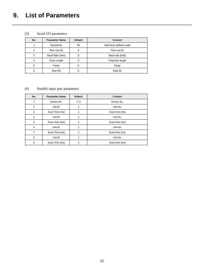
9. List of Parameters
.oN emaNretemaraP tluafeD tnetnoC
1 DIlanimreT 99 edocsserddapord-itluM
2 )S(tuOemiT 0 )S(tuoemiT
3 )s/tib(etaRduaB 3 )s/tib(etarduaB
4 htgneLraelC 0 htgnelretcarahC
5 ytiraP 0 ytiraP
6 tiBpotS 0 tibpotS
.oN emaNretemaraP tluafeD tnetnoC
1 .oNeciveD 3~1 .oNeciveD
2 DItinU 1 .oNtinU
3 )sm(emiTnacS 1 )sm(emitnacS
4 DItinU 1 .oNtinU
5 )sm(emiTnacS 1 )sm(emitnacS
6 DItinU 1 .oNtinU
7 )sm(emiTnacS 1 )sm(emitnacS
8 DItinU 1 .oNtinU
9 )sm(emiTnacS 1 )sm(emitnacS
(5) Serial I/O parameters
(6) Parallel input port parameters
23
9. List of Parameters
.oN emaNretemaraP tluafeD tnetnoC
1 eziSsixA 1 sexaforebmuN
2 rotaremuN 1 rotaremuN
3 rotanimoneD 1 rotanimoneD
4 )%(ediRrevO 001 edirrevO
5 )G(releccA 03.0 )G(rotcafnoitareleccA
6 )G(xaMreleccA 00.1 )G(rotcafnoitareleccamumixaM
7 )s/mm(leVevirD 001 )ces/mm(yticolevevirD
8 )s/mm(xaMleVevirD 0001 )ces/mm(yticolevevirdmumixaM
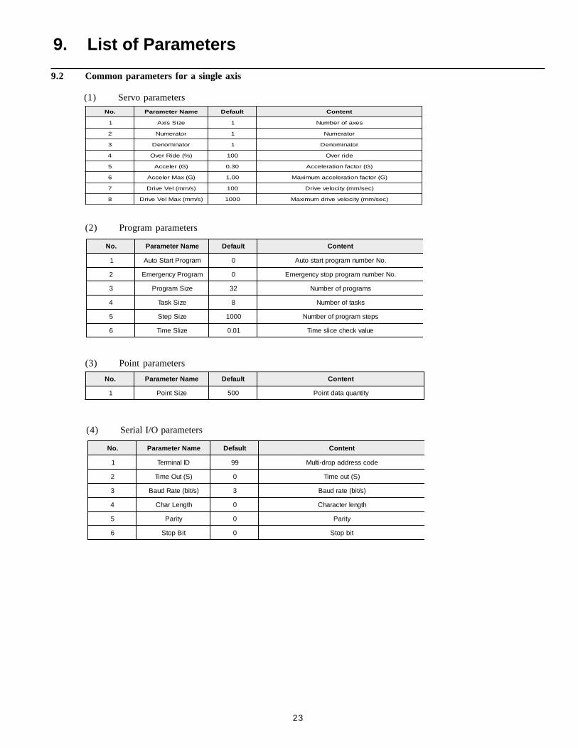
(1) Servo parameters
9.2 Common parameters for a single axis
(2) Program parameters
.oN emaNretemaraP tluafeD tnetnoC
1 margorPtratSotuA 0 .oNrebmunmargorptratsotuA
2 margorPycnegremE 0 .oNrebmunmargorppotsycnegremE
3 eziSmargorP 23 smargorpforebmuN
4 eziSksaT 8 sksatforebmuN
5 eziSpetS 0001 spetsmargorpforebmuN
6 ezilSemiT 10.0 eulavkcehcecilsemiT
(4) Serial I/O parameters
.oN emaNretemaraP tluafeD tnetnoC
1 eziStnioP 005 ytitnauqatadtnioP
(3) Point parameters
.oN emaNretemaraP tluafeD tnetnoC
1 DIlanimreT 99 edocsserddapord-itluM
2 )S(tuOemiT 0 )S(tuoemiT
3 )s/tib(etaRduaB 3 )s/tib(etarduaB
4 htgneLrahC 0 htgnelretcarahC
5 ytiraP 0 ytiraP
6 tiBpotS 0 tibpotS
24
.oN emaNretemaraP tluafeD tnetnoC
1 emaNsixA 8~1 emansixA
2 ecivreSovreS 004 )s/semit(ecivresovresfosemitfo.oN
3 rotaremuN 1 rotaremuN
4 rotanimoneD 1 rotanimoneD
5 )%(ediRrevO 001 )%(edirrevO
6 releccA 03.0 )G(noitareleccA
7 )s/mm(leVgoJ 03 )s/mm(yticolevgoJ
8 dnaBdneP 01 )eslup(dnabdnenoitisoP
9 tesffOtimiLtfoS 0.2 tesffotimilerawtfoS
01 )+(timiLtfoS 9999 )+(timiLtfoS
11 )-(timiLtfoS 0 )-(timiLtfoS
9. List of Parameters
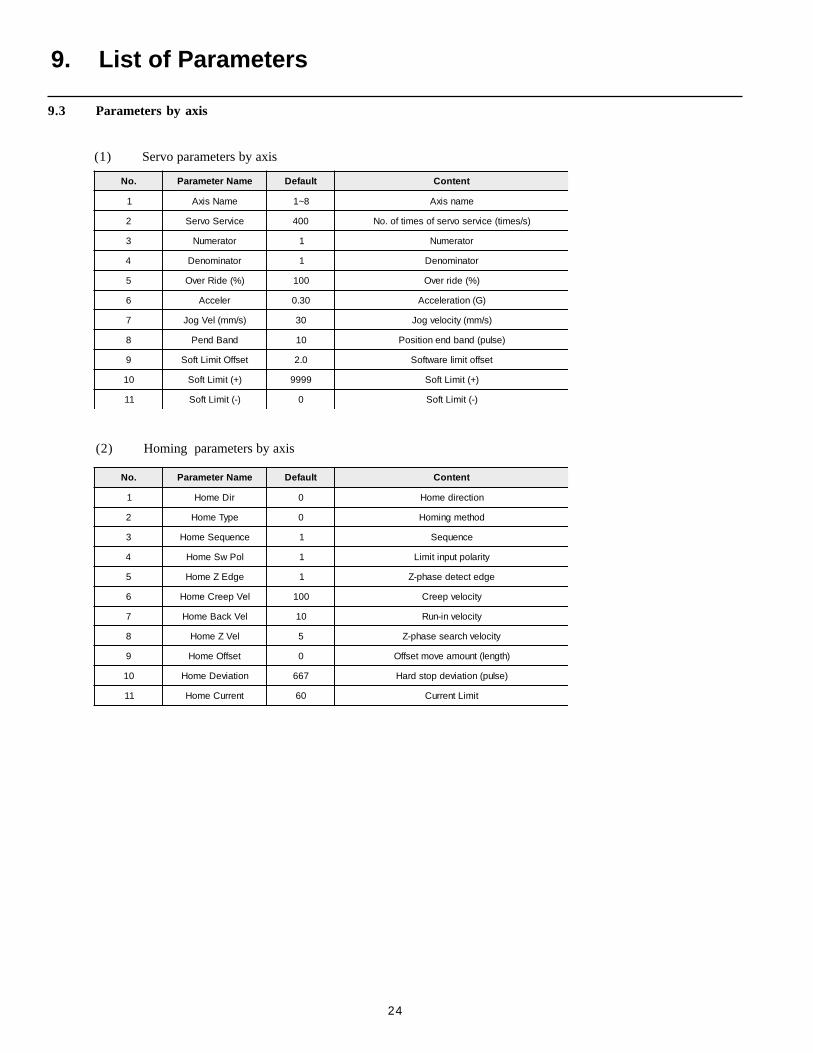
9.3 Parameters by axis
(1) Servo parameters by axis
(2) Homing parameters by axis
.oN emaNretemaraP tluafeD tnetnoC
1 riDemoH 0 noitceridemoH
2 epyTemoH 0 dohtemgnimoH
3 ecneuqeSemoH 1 ecneuqeS
4 loPwSemoH 1 ytiraloptupnitimiL
5 egdEZemoH 1 egdetcetedesahp-Z
6 leVpeerCemoH 001 yticolevpeerC
7 leVkcaBemoH 01 yticolevni-nuR
8 leVZemoH 5 yticolevhcraesesahp-Z
9 tesffOemoH 0 )htgnel(tnuomaevomtesffO
01 noitaiveDemoH 766 )eslup(noitaivedpotsdraH
11 tnerruCemoH 06 timiLtnerruC
25
.oN emaNretemaraP tluafeD tnetnoC
1 xaMMPRrotoM 0004 mumixamMPRrotoM
2 esluPredocnE 004 noituloverrepeslupredocnE
3 daeLwercS 8 )mm(daelwercS
4 elpitluM 4 reilpitlumeslupredocnE
5 emiTekarB 1.0 emitekarB
6 niaGnoitisoP 06 niagnoitisoP
7 niaGdeepS 08 niagdeepS
8 niaGF/F 0 niagdrawrofdeeF
9 niaGlargetnI 03 niaglargetnI
01 niaGlatoT 051 niaglatoT
11 tmL.tloV.tnI 06 timilegetalovlargetnI
21 deepSrevO 014 tnatsnocdeepsrevO
31 egnaRrorrE 6662 rorreevitalumuC
41 ruCxaMrotoM 09 tnerrucmumixamrotoM
51 daoLrevOrotoM 00361 timilrewoldaolrevorotoM
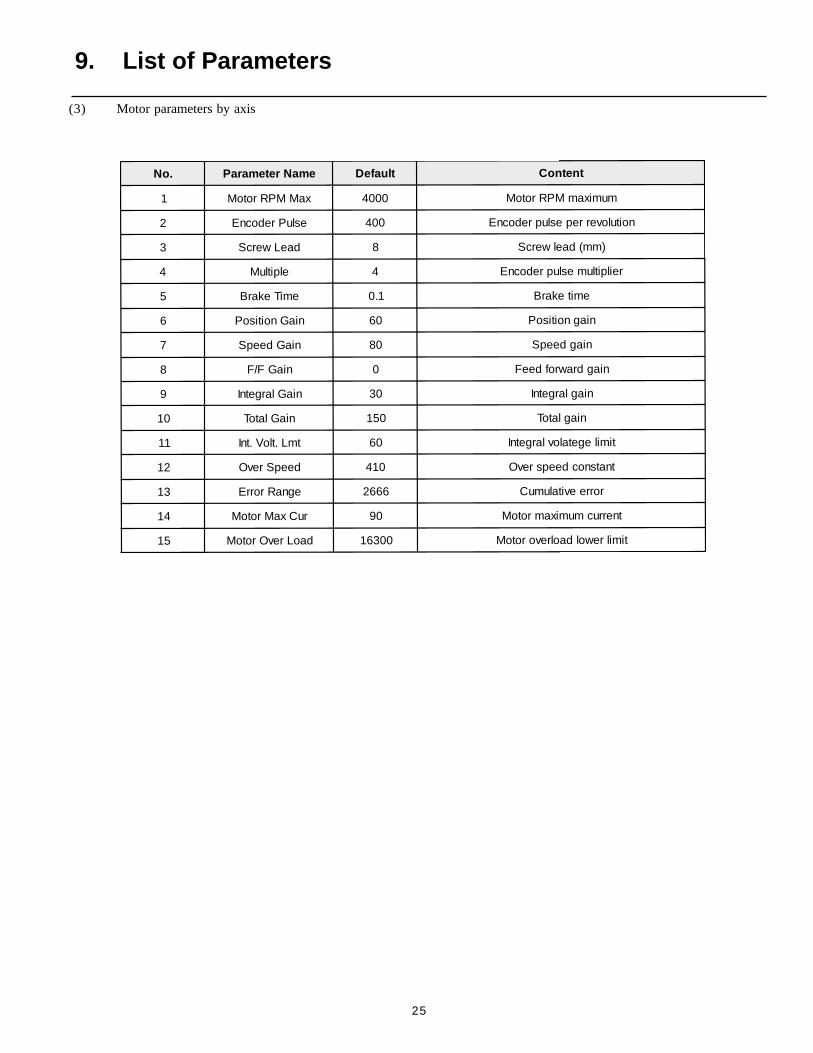
(3) Motor parameters by axis
9. List of Parameters
26
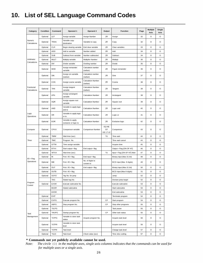
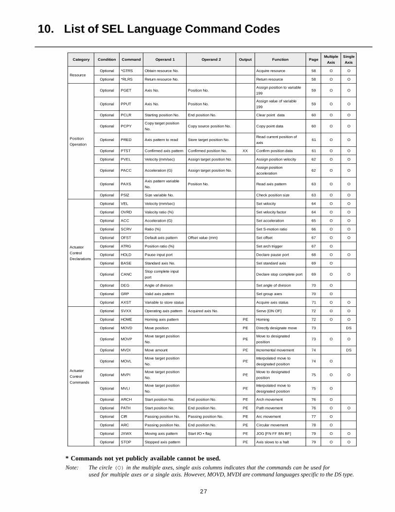
10. List of SEL Language Command Codes
yrogetaC noitidnoC dnammoC 1dnarepO 2dnarepO tuptuO noitcnuF egaPelpitluM
sixA
elgniS
sixA
ciremuN
snoitaluclaC
lanoitpO TEL elbairavngissA rebmuNngissA RZ ngissA 23 O O
lanoitpO NARTypocelbairaV
noitanitsedypocotelbairaV RZ ypoC 23 O O
lanoitpO RLC elbairavgniraelcnigeB elbairavraelcdnE RZ selbairavraelC 33 O O
citemhtirA
snoitaluclaC
lanoitpO DDA elbairavotddA deddarebmuN RZ ddA 43 O O
lanoitpO BUS elbairavmorftcartbuS detcartbusrebmuN RZ tcartbuS 43 O O
lanoitpO TLUM elbairavylpitluM rebmuNreilpitluM RZ ylpitluM 53 O O
lanoitpO VID elbairavediviD rebmungnidiviD RZ ediviD 53 O O
lanoitpO DOMredniamerngissA
elbairav
rebmunnoitaluclaC
)naidar(RZ redniamererugiF 63 O O
lanoitcnuF
snoitaluclaC
lanoitpO NISelbairavnisngissA
)naidar(
rebmunnoitaluclaC
)naidar(RZ eniS 73 O O
lanoitpO SOC elbairavenisocngissArebmuNnoitaluclaC
)naidar(RZ enisoC 83 O O
lanoitpO NATtnegnatngissA
elbairav
rebmuNnoitaluclaC
)naidar(RZ tnegnaT 83 O O
lanoitpO NTAtnegnatcrangissA
elbairavrebmuNnoitaluclaC RZ tnegnatcrA 83 O O
lanoitpO RQStoorerauqsngissA
elbairavrebmuNnoitaluclaC RZ toorerauqS 93 O O
cigoL
snoitarepO
lanoitpO DNAcigolylppaotelbairaV
otdnarebmuNnoitaluclaC RZ dnacigoL 04 O O
lanoitpO ROcigolylppaotelbairaV
otrorebmuNnoitaluclaC RZ rocigoL 14 O O
lanoitpO ROEylppaotelbairaV
otcigolroevisulcxerebmuNnoitaluclaC RZ cigolevisulcxE 24 O O
erapmoC lanoitpO XXPC elbairavnosirapmoC rebmuNnosirapmoC
QE EN
TG
EG TL EL
nosirapmoC 34 O O
remiT
lanoitpO WMIT )ces(emittiaW UT tiawemiT 44 O O
lanoitpO CMIT .oNmargorP lecnactiawemiT 44 O O
lanoitpO MTTG elbairavngissaemiT emiteriuqcA 54 O O
galF•O/I
snoitarepO
lanoitpO XXTB galf•tuptuotratS galf•tuptuodnE ]TNFONO[galF•tuptuO 64 O O
lanoitpO XXTW )ces(emittiaW UT tiaW]TNFONO[galF•tupnI 74 O O
lanoitpO NI galf•O/ItsriF galf•tupnidnE )tib13xaM(tupniyraniB 84 O O
lanoitpO BNI galf•O/ItsriFotstigidfo.oN
ottrevnoc)stigid8xaM(tupniDCB 94 O O
lanoitpO TUO galf•O/ItsriF galf•tuptuodnE )tib13xaM(tupniyraniB 05 O O
lanoitpO BTUO galf•O/ItsriF )stigid8xaM(tupniDCB 15 O O
margorP
lortnoC
lanoitpO OTOG pmujrof.oNgaT pmuJ 25 O O
GAT .oNgatdetatS tegratpmujeralceD 25 O O
lanoitpO RSXE .oNenituorbusetucexE enituorbusetucexE 35 O O
RSGB enituorbusdetatS enituorbustratS 35 O O
RSDE enituorbusdnE 35 O O
ksaT
tnemeganaM
lanoitpO TIXE margorpetanimreT 45 O O
lanoitpO GPXE .oNmargorpetucexE PC margorptratS 45 O O
lanoitpO GPBA .oNmargorppotS PC smargorprehtopotS 55 O O
lanoitpO GPLS* esuapksaT 55 O O
lanoitpO GPUW* .oNmargorpputratS PC sutatsksatrehtO 55 O O
lanoitpO GPTG*ksaterotsotelbairaV
sutats.oNmargorperiuqcA levelksateriuqcA 65 O O
lanoitpO RPTG*ksaterotsotelbairaV
levellevelksateriuqcA 65 O O
lanoitpO RPTS* levelksaT levelksategnahC 75 O O
lanoitpO CILS* levelksaT )ces(eulavkcehC gnittesecilsemiT 75 O O
* Commands not yet publicly available cannot be used.Note: The circle (O) in the multiple axes, single axis columns indicates that the commands can be used for
for multiple axes or a single axis.
27
yrogetaC noitidnoC dnammoC 1dnarepO 2dnarepO tuptuO noitcnuF egaPelpitluM
sixA
elgniS
sixA
ecruoseRlanoitpO SRTG* .oNecruoserniatbO ecruosereriuqcA 85 O O
lanoitpO SRLR* .oNecruosernruteR ecruosernruteR 85 O O
noitisoP
noitarepO
lanoitpO TEGP .oNsixA .oNnoitisoPelbairavotnoitisopngissA
99195 O O
lanoitpO TUPP .oNsixA .oNnoitisoPelbairavfoeulavngissA
99195 O O
lanoitpO RLCP .oNnoitisopgnitratS .oNnoitisopdnE atadtniopraelC 06 O O
lanoitpO YPCPnoitisoptegratypoC
.oN.oNnoitisopecruosypoC atadtniopypoC 06 O O
lanoitpO DERP daerotnrettapsixA .oNnoitisoptegraterotSfonoitisoptnerrucdaeR
sixa16 O O
lanoitpO TSTP nrettapsixademrifnoC .oNnoitisopdemrifnoC XX atadnoitisopmrifnoC 16 O O
lanoitpO LEVP )ces/mm(yticoleV .oNnoitisoptegratngissA yticolevnoitisopngissA 26 O O
lanoitpO CCAP )G(noitareleccA .oNnoitisoptegratngissAnoitisopngissA
noitarelecca26 O O
lanoitpO SXAPelbairavnrettapsixA
.oN.oNnoitisoP nrettapsixadaeR 36 O O
lanoitpO ZISP .oNelbairaveziS ezisnoitisopkcehC 36 O O
rotautcA
lortnoC
snoitaralceD
lanoitpO LEV )ces/mm(yticoleV yticolevteS 46 O O
lanoitpO DRVO )%(oitaryticolaV rotcafyticolevteS 46 O O
lanoitpO CCA )G(noitareleccA noitareleccateS 56 O O
lanoitpO VRCS )%(oitaR oitarnoitom-SteS 66 O O
lanoitpO TSFO nrettapsixatluafeD )mm(eulavtesffO tesffoteS 76 O O
lanoitpO GRTA )%(oitarnoitisoP reggirthcrateS 76 O
lanoitpO DLOH troptupniesuaP tropesuaperalceD 86 O O
lanoitpO ESAB .oNsixadradnatS sixadradnatsteS 96 O
lanoitpO CNACtupnietelpmocpotS
troptropetelpmocpotseralceD 96 O O
lanoitpO GED noisividfoelgnA noisividfoelgnateS 07 O
lanoitpO PRG nrettapsixadilaV sexapuorgteS 07 O
lanoitpO TSXA sutatserotsotelbairaV sutatssixaeriuqcA 17 O O
rotautcA
lortnoC
sdnammoC
lanoitpO XXVS nrettapsixagnitarepO .oNsixaderiuqcA ]FONO[ovreS 27 O O
lanoitpO EMOH nrettapsixagnimoH EP gnimoH 27 O O
lanoitpO DVOM noitisopevoM EP evometangisedyltceriD 37 SD
lanoitpO PVOMnoitisoptegratevoM
.oNEP
detangisedotevoM
noitisop37 O O
lanoitpO IDVM tnuomaevoM EP tnemevomlatnemercnI 47 SD
lanoitpO LVOMnoitisoptegratevoM
.oNEP
otevomdetalopretnI
noitisopdetangised47 O
lanoitpO IPVMnoitisoptegratevoM
.oNEP
detangisedotevoM
noitisop57 O O
lanoitpO ILVMnoitisoptegratevoM
.oNEP
otevomdetalopretnI
noitisopdetangised57 O
lanoitpO HCRA .oNnoitisoptratS .oNnoitisopdnE EP tnemevomhcrA 67 O
lanoitpO HTAP .oNnoitisoptratS .oNnoitisopdnE EP tnemevomhtaP 67 O O
lanoitpO RIC .oNnoitisopgnissaP .oNnoitisopgnissaP EP tnemevomcrA 77 O
lanoitpO CRA .oNnoitisopgnissaP .oNnoitisopdnE EP tnemevomralucriC 87 O
lanoitpO XWXJ nrettapsixagnivoM galf•O/ItratS EP ]FBNBFFNF[GOJ 97 O O
lanoitpO POTS nrettapsixadeppotS EP tlahaotswolssixA 97 O O
10. List of SEL Language Command Codes
Note: The circle (O) in the multiple axes, single axis columns indicates that the commands can be used forused for multiple axes or a single axis.
* Commands not yet publicly available cannot be used.
However, MOVD, MVDI are command languages specific to the DS type.
28
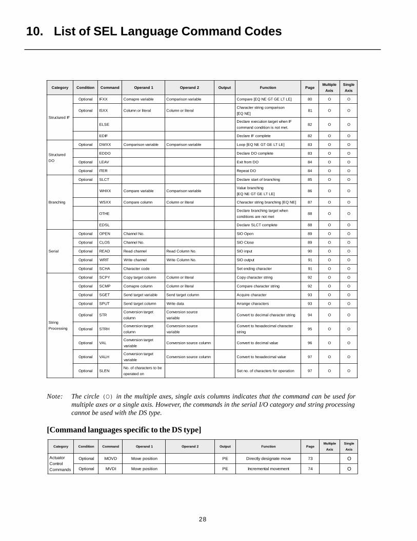
yrogetaC noitidnoC dnammoC 1dnarepO 2dnarepO tuptuO noitcnuF egaPelpitluM
sixA
elgniS
sixA
FIderutcurtS
lanoitpO XXFI elbairaverpamoC elbairavnosirapmoC ]ELTLEGTGENQE[erapmoC 08 O O
lanoitpO XXSI laretilronmuloC laretilronmuloCnosirapmocgnirtsretcarahC
]ENQE[18 O O
ESLEFInehwtegratnoitucexeeralceD
.temtonsinoitidnocdnammoc28 O O
FIDE etelpmocFIeralceD 28 O O
derutcurtS
OD
lanoitpO XXWD elbairavnosirapmoC elbairavnosirapmoC ]ELTLEGTGENQE[pooL 38 O O
ODDE etelpmocODeralceD 38 O O
lanoitpO VAEL ODmorftixE 48 O O
lanoitpO RETI ODtaepeR 48 O O
gnihcnarB
lanoitpO TCLS gnihcnarbfotratseralceD 58 O O
XXHW elbairaverapmoC elbairavnosirapmoCgnihcnarbeulaV
]ELTLEGTGENQE[68 O O
XXSW nmulocerapmoC laretilronmuloC ]ENQE[gnihcnarbgnirtsretcarahC 78 O O
EHTOnehwtegratgnihcnarberalceD
temtonerasnoitidnoc88 O O
LSDE etelpmocTCLSeralceD 88 O O
laireS
lanoitpO NEPO .oNlennahC nepOOIS 98 O O
lanoitpO SOLC .oNlennahC esolCOIS 98 O O
lanoitpO DAER lennahcdaeR .oNnmuloCdaeR tupniOIS 09 O O
lanoitpO TIRW lennahcetirW .oNnmuloCetirW tuptuoOIS 19 O O
lanoitpO AHCS edocretcarahC retcarahcgnidneteS 19 O O
gnirtS
gnissecorP
lanoitpO YPCS nmuloctegratypoC laretilronmuloC gnirtsretcarahcypoC 29 O O
lanoitpO PMCS nmulocerpamoC laretilronmuloC gnirtsretcarahcerapmoC 29 O O
lanoitpO TEGS elbairavtegratdneS nmuloctegratdneS retcarahceriuqcA 39 O O
lanoitpO TUPS nmuloctegratdneS atadetirW sretcarahcegnarrA 39 O O
lanoitpO RTStegratnoisrevnoC
nmuloc
ecruosnoisrevnoC
elbairavgnirtsretcarahclamicedottrevnoC 49 O O
lanoitpO HRTStegratnoisrevnoC
nmuloc
ecruosnoisrevnoC
elbairav
retcarahclamicedaxehottrevnoC
gnirts59 O O
lanoitpO LAVtegratnoisrevnoC
elbairavnmulocecruosnoisrevnoC eulavlamicedottrevnoC 69 O O
lanoitpO HLAVtegratnoisrevnoC
elbairavnmulocecruosnoisrevnoC eulavlamicedaxehottrevnoC 79 O O
lanoitpO NELSebotsretcarahcfo.oN
nodetareponoitareporofsretcarahcfo.onteS 79 O O
10. List of SEL Language Command Codes
Note: The circle (O) in the multiple axes, single axis columns indicates that the command can be used formultiple axes or a single axis. However, the commands in the serial I/O category and string processingcannot be used with the DS type.
[Command languages specific to the DS type]
yrogetaC noitidnoC dnammoC 1dnarepO 2dnarepO tuptuO noitcnuF egaPelpitluM
sixA
elgniS
sixA
rotautcAlortnoC
sdnammoC
lanoitpO DVOM noitisopevoM EP evometangisedyltceriD 37 O
lanoitpO IDVM noitisopevoM EP tnemevomlatnemercnI 47 O
29
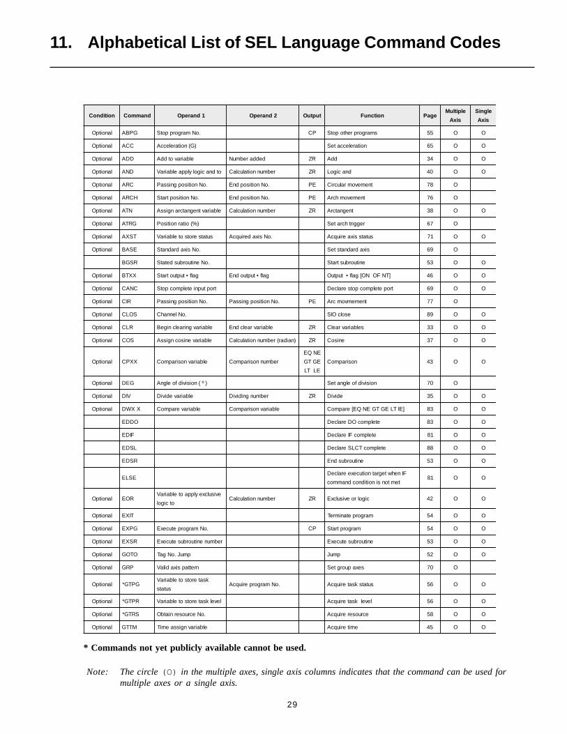
11. Alphabetical List of SEL Language Command Codes
noitidnoC dnammoC 1dnarepO 2dnarepO tuptuO noitcnuF egaPelpitluM
sixA
elgniS
sixA
lanoitpO GPBA .oNmargorppotS PC smargorprehtopotS 55 O O
lanoitpO CCA )G(noitareleccA noitareleccateS 56 O O
lanoitpO DDA elbairavotddA deddarebmuN RZ ddA 43 O O
lanoitpO DNA otdnacigolylppaelbairaV rebmunnoitaluclaC RZ dnacigoL 04 O O
lanoitpO CRA .oNnoitisopgnissaP .oNnoitisopdnE EP tnemevomralucriC 87 O
lanoitpO HCRA .oNnoitisoptratS .oNnoitisopdnE EP tnemevomhcrA 67 O
lanoitpO NTA elbairavtnegnatcrangissA rebmunnoitaluclaC RZ tnegnatcrA 83 O O
lanoitpO GRTA )%(oitarnoitisoP reggirthcrateS 76 O
lanoitpO TSXA sutatserotsotelbairaV .oNsixaderiuqcA sutatssixaeriuqcA 17 O O
lanoitpO ESAB .oNsixadradnatS sixadradnatsteS 96 O
RSGB .oNenituorbusdetatS enituorbustratS 35 O O
lanoitpO XXTB galf•tuptuotratS galf•tuptuodnE ]TNFONO[galf•tuptuO 64 O O
lanoitpO CNAC troptupnietelpmocpotS tropetelpmocpotseralceD 96 O O
lanoitpO RIC .oNnoitisopgnissaP .oNnoitisopgnissaP EP tnememvomcrA 77 O
lanoitpO SOLC .oNlennahC esolcOIS 98 O O
lanoitpO RLC elbairavgniraelcnigeB elbairavraelcdnE RZ selbairavraelC 33 O O
lanoitpO SOC elbairavenisocngissA )naidar(rebmunnoitaluclaC RZ enisoC 73 O O
lanoitpO XXPC elbairavnosirapmoC rebmunnosirapmoC
QE EN
TG EG
TL EL
nosirapmoC 34 O O
lanoitpO GED )º(noisividfoelgnA noisividfoelgnateS 07 O
lanoitpO VID elbairavediviD rebmungnidiviD RZ ediviD 53 O O
lanoitpO XXWD elbairaverapmoC elbairavnosirapmoC ]ElTLEGTGENQE[erapmoC 38 O O
ODDE etelpmocODeralceD 38 O O
FIDE etelpmocFIeralceD 18 O O
LSDE etelpmocTCLSeralceD 88 O O
RSDE enituorbusdnE 35 O O
ESLEFInehwtegratnoitucexeeralceD
temtonsinoitidnocdnammoc18 O O
lanoitpO ROEevisulcxeylppaotelbairaV
otcigolrebmunnoitaluclaC RZ cigolroevisulcxE 24 O O
lanoitpO TIXE margorpetanimreT 45 O O
lanoitpO GPXE .oNmargorpetucexE PC margorptratS 45 O O
lanoitpO RSXE rebmunenituorbusetucexE enituorbusetucexE 35 O O
lanoitpO OTOG pmuJ.oNgaT pmuJ 25 O O
lanoitpO PRG nrettapsixadilaV sexapuorgteS 07 O
lanoitpO GPTG*ksaterotsotelbairaV
sutats.oNmargorperiuqcA sutatsksateriuqcA 65 O O
lanoitpO RPTG* levelksaterotsotelbairaV levelksateriuqcA 65 O O
lanoitpO SRTG* .oNecruoserniatbO ecruosereriuqcA 85 O O
lanoitpO MTTG elbairavngissaemiT emiteriuqcA 54 O O
Note: The circle (O) in the multiple axes, single axis columns indicates that the command can be used formultiple axes or a single axis.
* Commands not yet publicly available cannot be used.

30
noitidnoC dnammoC 1dnarepO 2dnarepO tuptuO noitcnuF egaPelpitluM
sixA
elgniS
sixA
lanoitpO DLOH troptupniesuaP tropesuaperalceD 86 O O
lanoitpO EMOH nrettapsixagnimoH EP gnimoH 27 O O
lanoitpO XXFI elbairaverapmoC elbairavnosirapmoC ]ELTLEGTGENQE[erapmoC 08 O O
lanoitpO NI galf•O/ItsriF galf•tupnidnE )tib13xaM(tupniyraniB 84 O O
lanoitpO BNI galf•O/ItsriF ottrevnocotstigidfo.oN )stigid8xaM(tupniDCB 94 O O
lanoitpO XXSI nmulocerapmoC laretilronmuloCQE[nosirapmocgnirtsretcarahC
]EN18 O O
lanoitpO RETI ODtaepeR 48 O O
lanoitpO XWXJ nrettapsixagnivoM galf•O/ItratS EP ]FBNBFFNF[GOJ 97 O
lanoitpO VAEL ODmorftixE 48 O O
lanoitpO TEL elbairavngissA rebmunngissA RZ ngissA 23 O
lanoitpO DOM elbairavredniamerngissA )naidar(rebmunnoitaluclaC RZ redniamererugiF 63 O O
lanoitpO DVOM noitisopevoM EP evometangisedyltceriD 37 SD
lanoitpO LVOM .oNnoitisoptegratevoM EPdetangisedotevomdetalopretnI
noitisop47 O
lanoitpO PVOM .oNnoitisoptegratevoM EP noitisopdetangisedotevoM 37 O O
lanoitpO TLUM elbairavylpitluM rebmunreilpitluM RZ reilpitluM 53 O O
lanoitpO IDVM tnuomaevoM EP tnemevomlatnemercnI 47 SD
lanoitpO ILVM .oNnoitisoptegratevoM EPdetangisedotevomdetalopretnI
noitisop57 O
lanoitpO IPVM .oNnoitisoptegratevoM EP noitisopdetangisedotevoM 57 O O
lanoitpO TSFO nrettapsixatluafeD )mm(eulavtesffO tesffoteS 76 O O
lanoitpO NEPO .oNlennahC nepoOIS 98 O O
lanoitpO RO otrocigolylppaotelbairaV rebmunnoitaluclaC RZ rocigoL 14 O O
EHTOnehwtegratgnihcnarberalceD
temtonerasnoitidnoc88 O O
lanoitpO TUO galf•O/ItsriF galf•tupnidnE )tib13xaM(tupniyraniB 05 O O
lanoitpO BTUO galf•O/ItsriF )stigid8xaM(tupniDCB 15 O O
lanoitpO DRVO )%(oitaryticoleV rotcafyticolevteS 46 O O
lanoitpO CCAP )G(noitareleccA .oNnoitisoptegratngissA noitareleccanoitisopngissA 26 O O
lanoitpO HTAP .oNnoitisoptratS .oNnoitisopdnE EP tnemevomhtaP 67 O O
lanoitpO SXAP .oNelbairavnrettapsixA .oNnoitisoP nrettapsixadaeR 36 O O
lanoitpO RLCP .oNnoitisopgnitratS .oNnoitisopdnE atadtniopraelC 06 O O
lanoitpO YPCP .oNnoitisoptegratypoC .oNnoitisopecruosypoC atadtniopypoC 06 O O
lanoitpO TEGP .oNsixA .oNnoitisoP 991elbairavotnoitisopngissA 95 O O
lanoitpO TUPP .oNsixA .oNnoitisoP 991elbairavfonoitisopngissA 95 O O
lanoitpO DERP daerotnrettapsixA .oNnoitisoptegraterotS sixafonoitisoptnerrucdaeR 16 O O
lanoitpO ZISP .oNelbairaveziS ezisnoitisopkcehC 36 O O
lanoitpO TSTP nrettapsixademrifnoC .oNnoitisopdemrifnoC XX atadnoitisopmrifnoC 16 O O
lanoitpO LEVP )ces/mm(yticoleV .oNnoitisoptegratngissA yticolevnoitisopngissA 26 O O
11. Alphabetical List of SEL Language Command Codes
Note: The circle (O) in the multiple axes, single axis columns indicates that the command can be used formultiple axes or a single axis. However, MOVD, MVDI are command languages specific to the DS type.
* Commands not yet publicly available cannot be used.

31
11. Alphabetical List of SEL Language Command Codes
* Commands not yet publicly available cannot be used.
noitidnoC dnammoC 1dnarepO 2dnarepO tuptuO noitcnuF egaPelpitluM
sixA
elgniS
sixA
lanoitpO DAER lennahcdaeR rebmunnmulocdaeR tupptuoOIS 09 O O
lanoitpO SRLR* ecruosernruteR ecruosereriuqcA 85 O O
lanoitpO AHCS edocretcarahC retcarahcgnidneteS 19 O O
lanoitpO PMCS nmulocerapmoC laretilronmuloC gnirtsretcarahcerpamoC 29 O O
lanoitpO YPCS nmuloctegratypoC laretilronmuloC gnirtsretcarahcypoC 29 O O
lanoitpO VRCS )%(oitaR oitarnoitom-SteS 66 O O
lanoitpO TEGS elbairavtegratdneS nmuloctegratdneS retcarahceriuqcA 39 O O
lanoitpO NIS elbairavnisngissA )naidar(rebmunnoitaluclaC RZ eniS 73 O O
lanoitpO TCLS gnihcnarbfotratseralceD 58 O O
lanoitpO NELSebotsretcarahcforebmuN
nodetarepo
rofsretcarahcfosrebmunteS
noitarepo79 O
lanoitpO CILS* levelksaT )ces(eulavkcehC gnittesecilsemiT 75 O O
lanoitpO GPLS* esuapksaT 55 SD
lanoitpO TUPS nmuloctegratdneS atadetirW sretcarahcegnarrA 39 O O
lanoitpO RQS elbairavtooreruqsngissA rebmunnoitaluclaC RZ toorerauqS 93 O O
lanoitpO POTS nrettapsixadeppotS EP tlahaotswolssixA 97 O O
lanoitpO RPTS* levelksaT levelksategnahC 75 SD
lanoitpO RTS nmuloctegratnoisrenoC elbairavecruosnoisrevnoC gnirtsretcarahclamicedottrevnoC 49 O
lanoitpO HRTS nmuloctegratnoisrevnoC elbairavecruosnoisrevnoCretcarahclamicedaxehottrevnoC
gnirts59 O O
lanoitpO BUS elbairavmorftcartbuS detcartbusrebmuN RZ tcartbuS 43 O O
lanoitpO XXVS nrettapsixagnitarepO ]FONO[ovreS 27 O O
lanoitpO GAT .oNgatdetatS tegratpmujeralceD 25 O O
lanoitpO NAT elbairavtnegnatngissA )naidar(rebmunnoitaluclaC RZ tnegnaT 83 O O
lanoitpO CMIT .oNmargorP lecnactiawemiT 44 O O
lanoitpO WMIT )ces(emittiaW UT tiawemiT 44 O O
lanoitpO NART noitanitsedypocelbairaV ypocotelbairaV RZ ypoC 23 O O
lanoitpO LAV elbairavtegratnoisrevnoC nmulocecruosnoisrevnoC eulavlamicedottrevnoC 69 O O
lanoitpO HLAV elbairavtegratnoisrevnoC nmulocecruosnoisrevnoC eulavlamicedaxehottrevnoC 79 O O
lanoitpO LEV )ces/mm(yticoleV yticolevteS 46 O O
lanoitpO XXHW elbairaverapmoC elbairavnosirapmoC ]ELTLEGTGENQEpooL 68 O O
lanoitpO TIRW 19 O O
lanoitpO XXSW nmulocerapmoC laretilronmuloC ]ENQE[gnihcnarbgnirtsretcarahC 78 O O
lanoitpO XXTW galf•O/I emittiaW UT tiaw]FONO[galf•tupnI 74 O O
lanoitpO GPUW* .oNmargorPputratS PC putratsksatrehtO 55 O O
Note: The circle (O) in the multiple axes, single axis columns indicates that the command can be used for multiple axes or a single axis. However, MOVD, MVDI are command languages specific to the DS type.
32
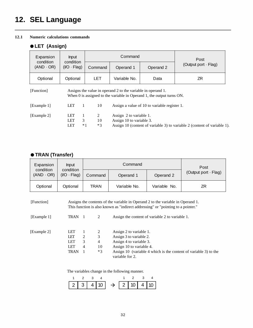
[Function] Assigns the contents of the variable in Operand 2 to the variable in Operand 1.This function is also known as "indirect addressing" or "pointing to a pointer."
[Example 1] TRAN 1 2 Assign the content of variable 2 to variable 1.
[Example 2] LET 1 2 Assign 2 to variable 1.LET 2 3 Assign 3 to variable 2.LET 3 4 Assign 4 to variable 3.LET 4 10 Assign 10 to variable 4.TRAN 1 *3 Assign 10 (variable 4 which is the content of variable 3) to the
variable for 2.
410
1 23
2 3 10
12 3
noisnapxEnoitidnoc
)RO·DNA(
tupnInoitidnoc)galF·O/I(
dnammoCtsoP
)galF·troptuptuO(dnammoC 1dnarepO 2dnarepO
lanoitpO lanoitpO NART .oNelbairaV .oNelbairaV RZ
12. SEL Language
noisnapxEnoitidnoc
)RO·DNA(
tupnInoitidnoc)galF·O/I(
dnammoCtsoP
)galF·troptuptuO(dnammoC 1dnarepO 2dnarepO
lanoitpO lanoitpO TEL .oNelbairaV ataD RZ
12.1 Numeric calculations commands
LET (Assign)
[Function] Assigns the value in operand 2 to the variable in operand 1.When 0 is assigned to the variable in Operand 1, the output turns ON.
[Example 1] LET 1 10 Assign a value of 10 to variable register 1.
[Example 2] LET 1 2 Assign 2 to variable 1.LET 3 10 Assign 10 to variable 3.LET *1 *3 Assign 10 (content of variable 3) to variable 2 (content of variable 1).
TRAN (Transfer)
The variables change in the following manner.
4 4
104 2
33
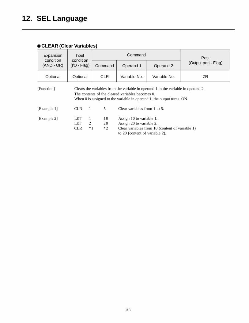
[Function] Clears the variables from the variable in operand 1 to the variable in operand 2.The contents of the cleared variables becomes 0.When 0 is assigned to the variable in operand 1, the output turns ON.
[Example 1] CLR 1 5 Clear variables from 1 to 5.
[Example 2] LET 1 10 Assign 10 to variable 1.LET 2 20 Assign 20 to variable 2.CLR *1 *2 Clear variables from 10 (content of variable 1)
to 20 (content of variable 2).
12. SEL Language
noisnapxEnoitidnoc
)RO·DNA(
tupnInoitidnoc)galF·O/I(
dnammoCtsoP
)galF·troptuptuO(dnammoC 1dnarepO 2dnarepO
lanoitpO lanoitpO RLC .oNelbairaV .oNelbairaV RZ
CLEAR (Clear Variables)
34
12. SEL Language
SUB (Subtract)
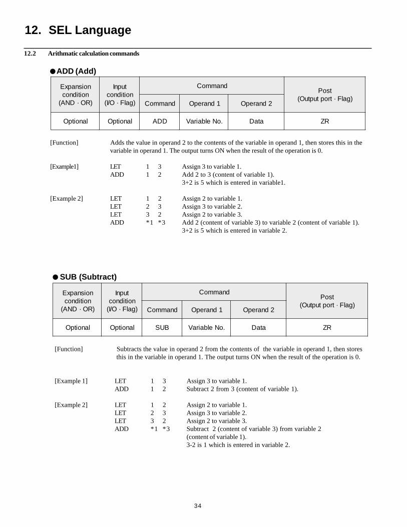
[Function] Adds the value in operand 2 to the contents of the variable in operand 1, then stores this in thevariable in operand 1. The output turns ON when the result of the operation is 0.
[Example1] LET 1 3 Assign 3 to variable 1.ADD 1 2 Add 2 to 3 (content of variable 1).
3+2 is 5 which is entered in variable1.
[Example 2] LET 1 2 Assign 2 to variable 1.LET 2 3 Assign 3 to variable 2.LET 3 2 Assign 2 to variable 3.ADD *1 *3 Add 2 (content of variable 3) to variable 2 (content of variable 1).
3+2 is 5 which is entered in variable 2.
noisnapxEnoitidnoc
)RO·DNA(
tupnInoitidnoc)galF·O/I(
dnammoCtsoP
)galF·troptuptuO(dnammoC 1dnarepO 2dnarepO
lanoitpO lanoitpO DDA .oNelbairaV ataD RZ
ADD (Add)
noisnapxEnoitidnoc
)RO·DNA(
tupnInoitidnoc)galF·O/I(
dnammoCtsoP
)galF·troptuptuO(dnammoC 1dnarepO 2dnarepO
lanoitpO lanoitpO BUS .oNelbairaV ataD RZ
[Function] Subtracts the value in operand 2 from the contents of the variable in operand 1, then stores this in the variable in operand 1. The output turns ON when the result of the operation is 0.
[Example 1] LET 1 3 Assign 3 to variable 1.ADD 1 2 Subtract 2 from 3 (content of variable 1).
[Example 2] LET 1 2 Assign 2 to variable 1.LET 2 3 Assign 3 to variable 2.LET 3 2 Assign 2 to variable 3.ADD *1 *3 Subtract 2 (content of variable 3) from variable 2
(content of variable 1).3-2 is 1 which is entered in variable 2.
12.2 Arithmatic calculation commands
35
12. SEL Language
noisnapxEnoitidnoc
)RO·DNA(
tupnInoitidnoc)galF·O/I(
dnammoCtsoP
)galF·troptuptuO(dnammoC 1dnarepO 2dnarepO
lanoitpO lanoitpO TLUM .oNelbairaV ataD RZ
MULT (Multiply)
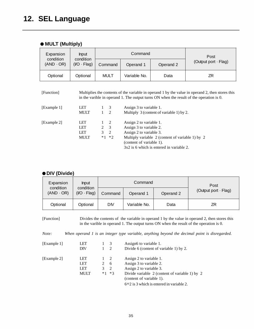
[Function] Multiplies the contents of the variable in operand 1 by the value in operand 2, then stores thisin the varible in operand 1. The output turns ON when the result of the operation is 0.
[Example 1] LET 1 3 Assign 3 to variable 1.MULT 1 2 Multiply 3 (content of variable 1) by 2.
[Example 2] LET 1 2 Assign 2 to variable 1.LET 2 3 Assign 3 to variable 2.LET 3 2 Assign 2 to variable 3.MULT *1 *2 Multiply variable 2 (content of variable 1) by 2
(content of variable 1).3x2 is 6 which is entered in variable 2.
noisnapxEnoitidnoc
)RO·DNA(
tupnInoitidnoc)galF·O/I(
dnammoCtsoP
)galF·troptuptuO(dnammoC 1dnarepO 2dnarepO
lanoitpO lanoitpO VID .oNelbairaV ataD RZ
[Function] Divides the contents of the variable in operand 1 by the value in operand 2, then stores thisin the varible in operand 1. The output turns ON when the result of the operation is 0.
Note: When operand 1 is an integer type variable, anything beyond the decimal point is disregarded.
[Example 1] LET 1 3 Assign6 to variable 1.DIV 1 2 Divide 6 (content of variable 1) by 2.
[Example 2] LET 1 2 Assign 2 to variable 1.LET 2 6 Assign 3 to variable 2.LET 3 2 Assign 2 to variable 3.MULT *1 *3 Divide variable 2 (content of variable 1) by 2
(content of variable 1).6÷2 is 3 which is entered in variable 2.
DIV (Divide)
36
12. SEL Language
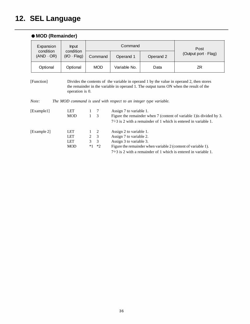
[Function] Divides the contents of the variable in operand 1 by the value in operand 2, then storesthe remainder in the variable in operand 1. The output turns ON when the result of theoperation is 0.
Note: The MOD command is used with respect to an integer type variable.
[Example1] LET 1 7 Assign 7 to variable 1.MOD 1 3 Figure the remainder when 7 (content of variable 1)is divided by 3.
7÷3 is 2 with a remainder of 1 which is entered in variable 1.
[Example 2] LET 1 2 Assign 2 to variable 1.LET 2 3 Assign 7 to variable 2.LET 3 3 Assign 3 to variable 3.MOD *1 *2 Figure the remainder when variable 2 (content of variable 1).
7÷3 is 2 with a remainder of 1 which is entered in variable 1.
noisnapxEnoitidnoc
)RO·DNA(
tupnInoitidnoc)galF·O/I(
dnammoCtsoP
)galF·troptuptuO(dnammoC 1dnarepO 2dnarepO
lanoitpO lanoitpO DOM .oNelbairaV ataD RZ
MOD (Remainder)
37
12. SEL Language
noisnapxEnoitidnoc
)RO·DNA(
tupnInoitidnoc)galF·O/I(
dnammoCtsoP
)galF·troptuptuO(dnammoC 1dnarepO 2dnarepO
lanoitpO lanoitpO NIS .oNelbairaV ataD RZ
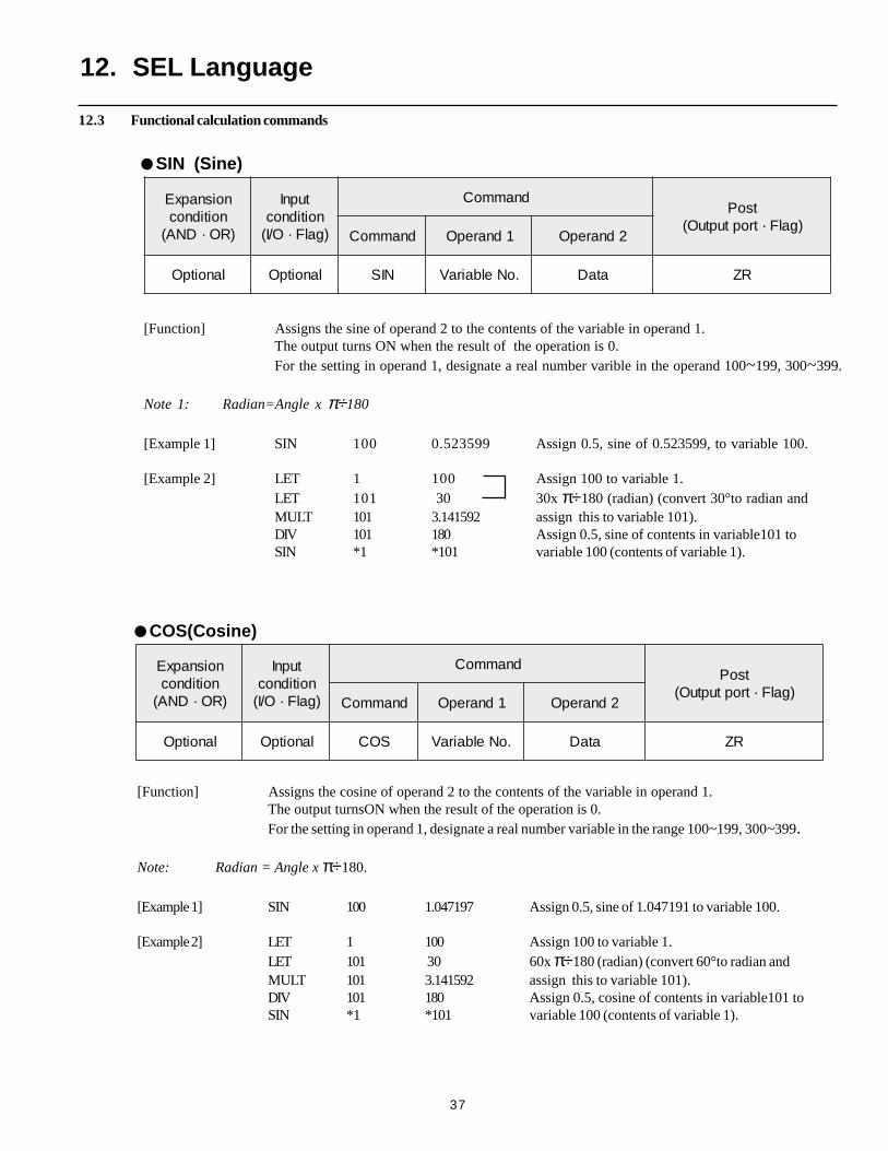
SIN (Sine)
[Function] Assigns the sine of operand 2 to the contents of the variable in operand 1.The output turns ON when the result of the operation is 0.For the setting in operand 1, designate a real number varible in the operand 100~199, 300~399.
Note 1: Radian=Angle x π÷180
[Example 1] SIN 100 0.523599 Assign 0.5, sine of 0.523599, to variable 100.
[Example 2] LET 1 100 Assign 100 to variable 1.LET 101 30 30x π÷180 (radian) (convert 30°to radian andMULT 101 3.141592 assign this to variable 101).DIV 101 180 Assign 0.5, sine of contents in variable101 toSIN *1 *101 variable 100 (contents of variable 1).
noisnapxEnoitidnoc
)RO·DNA(
tupnInoitidnoc)galF·O/I(
dnammoCtsoP
)galF·troptuptuO(dnammoC 1dnarepO 2dnarepO
lanoitpO lanoitpO SOC .oNelbairaV ataD RZ
[Function] Assigns the cosine of operand 2 to the contents of the variable in operand 1.The output turnsON when the result of the operation is 0.For the setting in operand 1, designate a real number variable in the range 100~199, 300~399.
Note: Radian = Angle x π÷180.
[Example 1] SIN 100 1.047197 Assign 0.5, sine of 1.047191 to variable 100.
[Example 2] LET 1 100 Assign 100 to variable 1.LET 101 30 60x π÷180 (radian) (convert 60°to radian andMULT 101 3.141592 assign this to variable 101).DIV 101 180 Assign 0.5, cosine of contents in variable101 toSIN *1 *101 variable 100 (contents of variable 1).
COS(Cosine)
12.3 Functional calculation commands
38
12. SEL Language
noisdnapxEnoitidnoc
)RO·DNA(
tupnInoitidnoc)galF·O/I(
dnammoCtsoP
)galF·troptuptuO(dnammoC 1dnarepO 2dnarepO
lanoitpO lanoitpO NAT .oNelbairaV ataD RZ
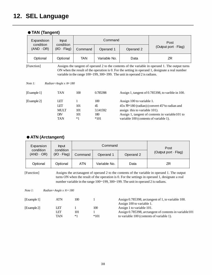
TAN (Tangent)
[Function] Assigns the tangent of operand 2 to the contents of the variable in operand 1. The output turnsON when the result of the operation is 0. For the setting in operand 1, designate a real numbervariable in the range 100~199, 300~399. The unit in operand 2 is radians.
Note 1: Radian=Angle x π÷ 180
[Example 1] TAN 100 0.785398 Assign 1, tangent of 0.785398, to varible in 100.
[Example 2] LET 1 100 Assign 100 to variable 1.LET 101 45 45x π÷180 (radian) (convert 45°to radian andMULT 101 3.141592 assign this to variable 101).DIV 101 180 Assign 1, tangent of contents in variable101 toTAN *1 *101 variable 100 (contents of variable 1).
noisnapxEnoitidnoc
)RO·DNA(
tupnInoitidnoc)galF·O/I(
dnammoCtsoP
)galF·troptuptuO(dnammoC 1dnarepO 2dnarepO
lanoitpO lanoitpO NTA .oNelbairaV ataD RZ
[Function] Assigns the arctanagent of operand 2 to the contents of the variable in operand 1. The outputturns ON when the result of the operation is 0. For the settings in operand 1, designate a realnumber variable in the range 100~199, 300~199. The unit in operand 2 is radians.
Note 1: Radian=Angle x π ÷ 180
[Example 1] ATN 100 1 Assign 0.785398, arctangent of 1, to variable 100.Assign 100 to variable 1.
[Example 2] LET 1 100 Assign 1 to variable 101.LET 101 1 Assign 0.785398, arctangent of contents in variable101TAN *1 *101 to variable 100 (contents of variable 1).
ATN (Arctangent)
39
12. SEL Language
noisnapxEnoitidnoc
)RO·DNA(
tupnInoitidnoc)galF·O/I(
dnammoCtsoP
)galF·troptuptuO(dnammoC 1dnarepO 2dnarepO
lanoitpO lanoitpO RQS .oNelbairaV ataD RZ
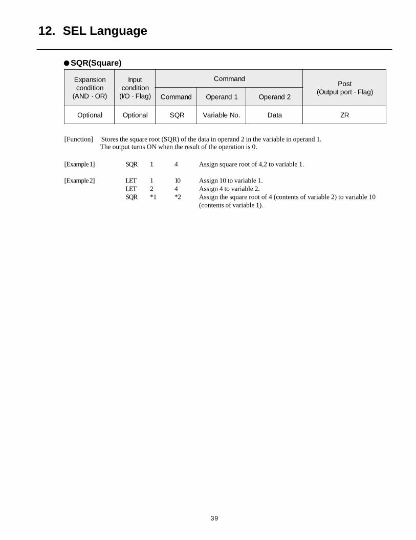
SQR(Square)
[Function] Stores the square root (SQR) of the data in operand 2 in the variable in operand 1.
[Example 1] SQR 1 4 Assign square root of 4,2 to variable 1.
[Example 2] LET 1 10 Assign 10 to variable 1.LET 2 4 Assign 4 to variable 2.SQR *1 *2 Assign the square root of 4 (contents of variable 2) to variable 10
(contents of variable 1).
The output turns ON when the result of the operation is 0.
40
12. SEL Language
noisdnapxEnoitidnoc
)RO·DNA(
tupnInoitidnoc)galF·O/I(
dnammoCtsoP
)galF·troptuptuO(dnammoC 1dnarepO 2dnarepO
lanoitpO lanoitpO DNA .oNelbairaV ataD RZ
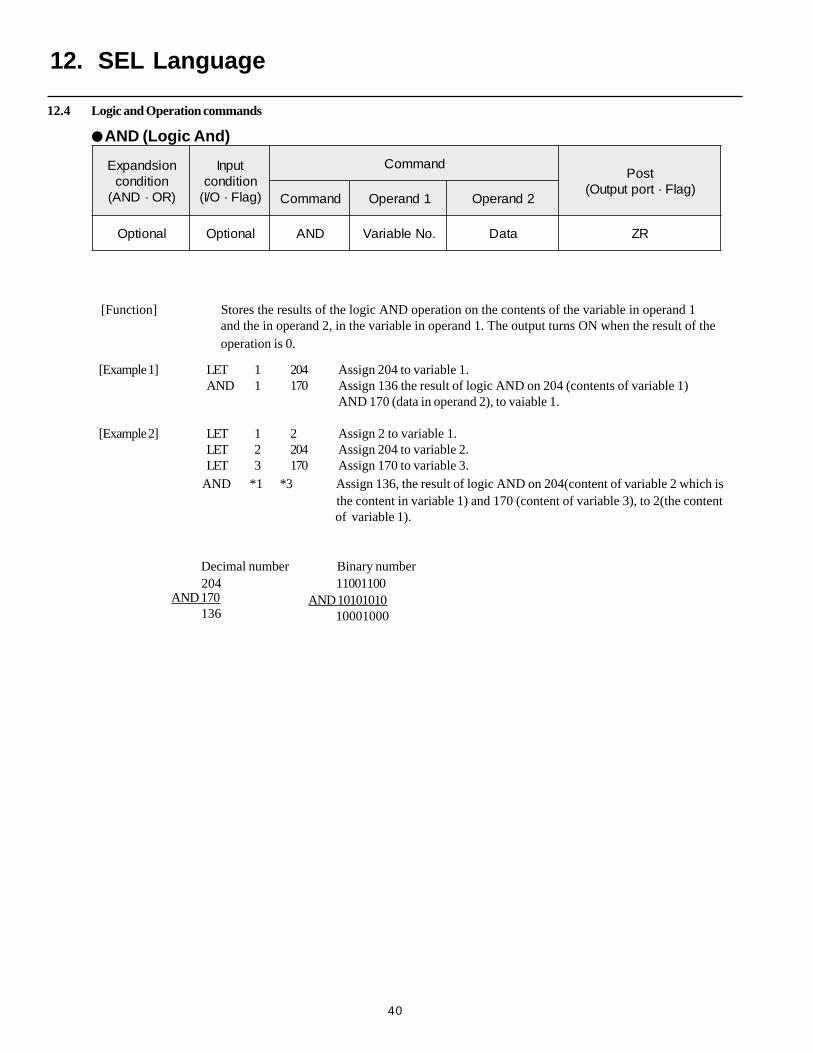
AND (Logic And)
[Function] Stores the results of the logic AND operation on the contents of the variable in operand 1and the in operand 2, in the variable in operand 1. The output turns ON when the result of theoperation is 0.
[Example 1] LET 1 204 Assign 204 to variable 1.AND 1 170 Assign 136 the result of logic AND on 204 (contents of variable 1)
AND 170 (data in operand 2), to vaiable 1.
[Example 2] LET 1 2 Assign 2 to variable 1.LET 2 204 Assign 204 to variable 2.LET 3 170 Assign 170 to variable 3.
AND *1 *3 Assign 136, the result of logic AND on 204(content of variable 2 which is the content in variable 1) and 170 (content of variable 3), to 2(the content of variable 1).
Decimal number Binary number 204 11001100
AND 10101010 10001000
AND 170 136
12.4 Logic and Operation commands
41
noisnapxEnoitidnoc
)RO·DNA(
tupnInoitidnoc)galF·O/I(
dnammoCtsoP
)galF·troptuptuO(dnammoC 1dnarepO 2dnarepO
lanoitpO lanoitpO RO .oNelbairaV ataD RZ
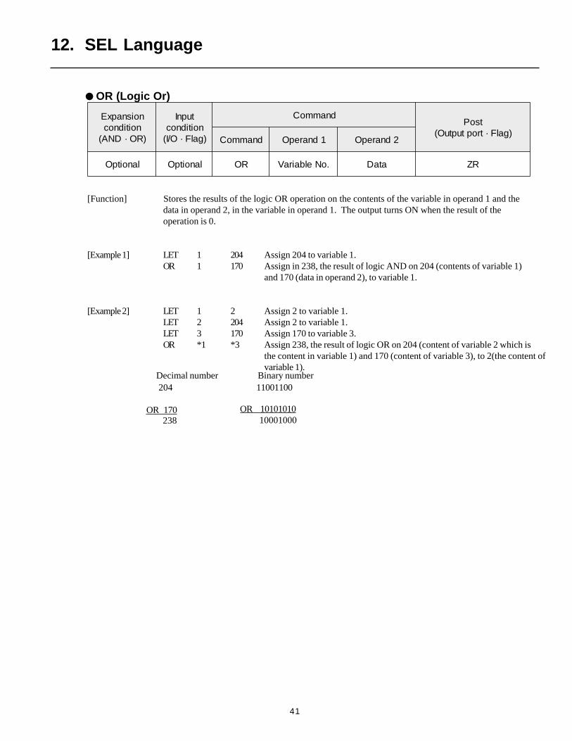
OR (Logic Or)
[Function] Stores the results of the logic OR operation on the contents of the variable in operand 1 and thedata in operand 2, in the variable in operand 1. The output turns ON when the result of theoperation is 0.
[Example 1] LET 1 204 Assign 204 to variable 1.OR 1 170 Assign in 238, the result of logic AND on 204 (contents of variable 1)
and 170 (data in operand 2), to variable 1.
[Example 2] LET 1 2 Assign 2 to variable 1.LET 2 204 Assign 2 to variable 1.LET 3 170 Assign 170 to variable 3.OR *1 *3 Assign 238, the result of logic OR on 204 (content of variable 2 which is
the content in variable 1) and 170 (content of variable 3), to 2(the content ofvariable 1).
12. SEL Language
OR 170
Decimal number Binary number 204 11001100
OR 10101010 10001000 238
42
noisnapxEnoitidnoc
)RO·DNA(
tupnInoitidnoc)galF·O/I(
dnammoCtsoP
)galF·troptuptuO(dnammoC 1dnarepO 2dnarepO
lanoitpO lanoitpO ROE .oNelbairaV ataD RZ
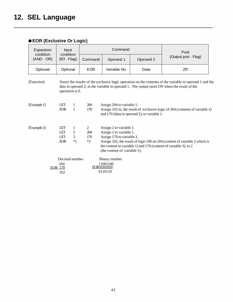
EOR (Exclusive Or Logic)
[Function] Stores the results of the exclusive logic operation on the contents of the variable in operand 1 and thedata in operand 2, in the variable in operand 1. The output turns ON when the result of theoperation is 0.
[Example 1] LET 1 204 Assign 204 to variable 1.EOR 1 170 Assign 102 in, the result of exclusive logic of 204 (contents of variable 1)
and 170 (data in operand 2), to variable 1.
[Example 2] LET 1 2 Assign 2 to variable 1.LET 2 204 Assign 2 to variable 1.LET 3 170 Assign 170 to variable 3.EOR *1 *3 Assign 102, the result of logic OR on 204 (content of variable 2 which is
the content in variable 1) and 170 (content of variable 3), to 2(the content of variable 1).
12. SEL Language
EOR 170
Decimal number Binary number 204 11001100
102EOR10101010 0110110
43
noisnapxEnoitidnoc
)RO·DNA(
tupnInoitidnoc)galF·O/I(
dnammoCtsoP
)galF·troptuptuO(dnammoC 1dnarepO 2dnarepO
lanoitpO lanoitpO XXPC .oNelbairaV ataDQE ENTG EGTL EL
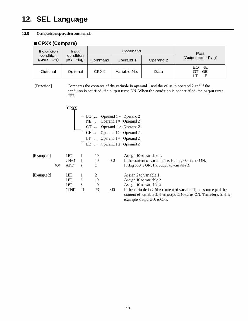
CPXX (Compare)
[Function] Compares the contents of the variable in operand 1 and the value in operand 2 and if thecondition is satisfied, the output turns ON. When the condition is not satisfied, the output turnsOFF.
12. SEL Language
[Example 1] LET 1 10 Assign 10 to variable 1.CPEQ 1 10 600 If the content of variable 1 is 10, flag 600 turns ON,
600 ADD 2 1 If flag 600 is ON, 1 is added to variable 2.
[Example 2] LET 1 2 Assign 2 to variable 1.LET 2 10 Assign 10 to variable 2.LET 3 10 Assign 10 to variable 3.CPNE *1 *3 310 If the variable in 2 (the content of variable 1) does not equal the
content of variable 3, then output 310 turns ON. Therefore, in thisexample, output 310 is OFF.
CPXX
EQ ... Operand 1 = Operand 2NE ... Operand 1 ≠ Operand 2GT ... Operand 1 > Operand 2
GE ... Operand 1 ≥ Operand 2
LT ... Operand 1 < Operand 2
LE ... Operand 1 ≤ Operand 2
12.5 Comparison operation commands
44
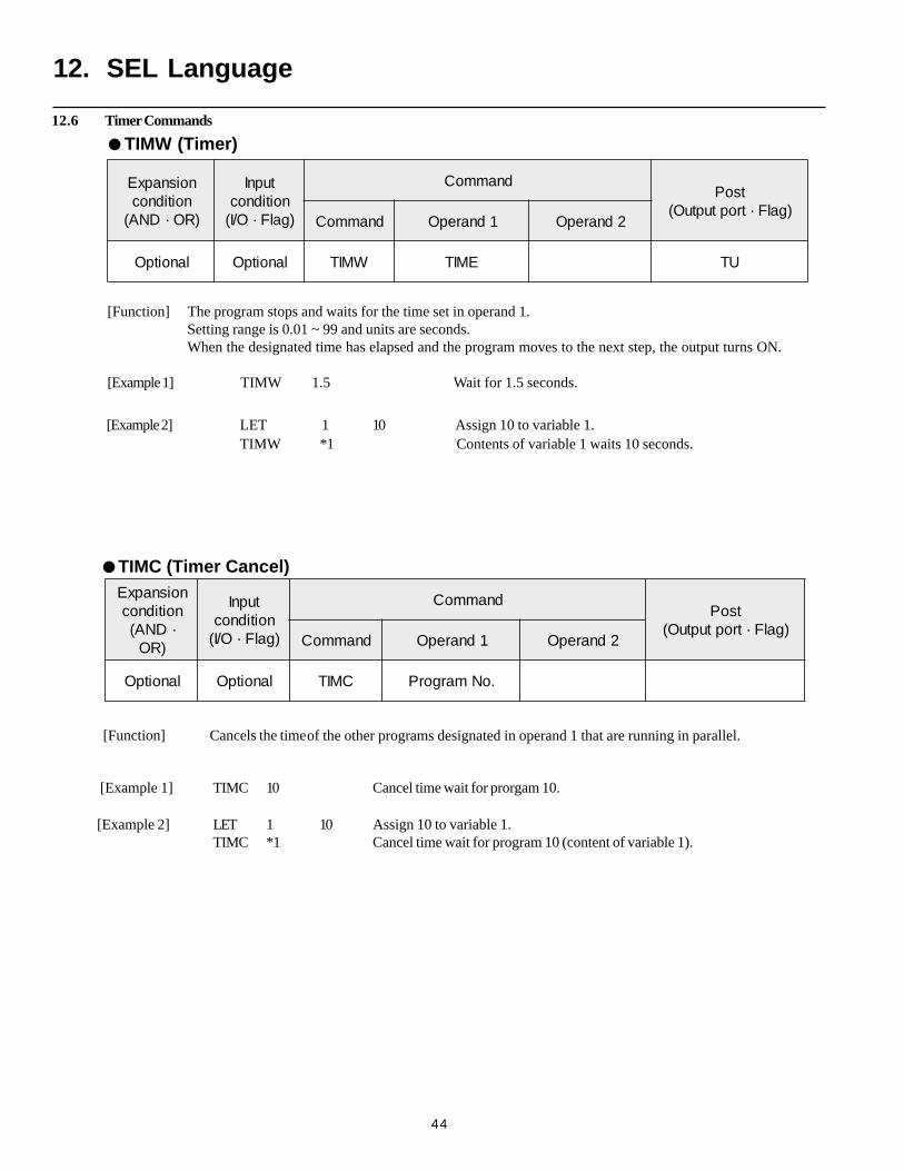
12.6 Timer Commands
[Function] The program stops and waits for the time set in operand 1.Setting range is 0.01 ~ 99 and units are seconds.When the designated time has elapsed and the program moves to the next step, the output turns ON.
[Example 1] TIMW 1.5 Wait for 1.5 seconds.
12. SEL Language
TIMW (Timer)
noisnapxEnoitidnoc
)RO·DNA(
tupnInoitidnoc)galF·O/I(
dnammoCtsoP
)galF·troptuptuO(dnammoC 1dnarepO 2dnarepO
lanoitpO lanoitpO WMIT EMIT UT
[Example 2] LET 1 10 Assign 10 to variable 1. TIMW *1 Contents of variable 1 waits 10 seconds.
noisnapxEnoitidnoc·DNA(
)RO
tupnInoitidnoc)galF·O/I(
dnammoCtsoP
)galF·troptuptuO(dnammoC 1dnarepO 2dnarepO
lanoitpO lanoitpO CMIT .oNmargorP
TIMC (Timer Cancel)
[Function] Cancels the time of the other programs designated in operand 1 that are running in parallel.
[Example 1] TIMC 10 Cancel time wait for prorgam 10.
[Example 2] LET 1 10 Assign 10 to variable 1.TIMC *1 Cancel time wait for program 10 (content of variable 1).
45
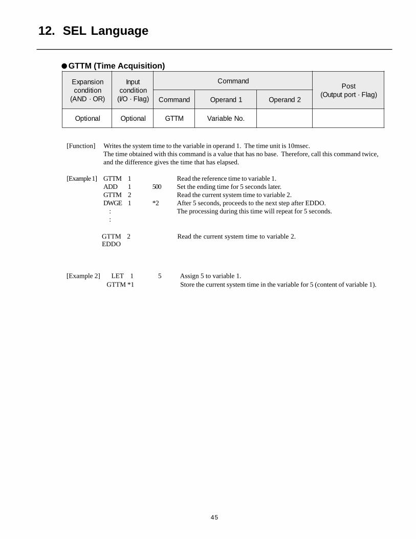
[Function] Writes the system time to the variable in operand 1. The time unit is 10msec.The time obtained with this command is a value that has no base. Therefore, call this command twice,and the difference gives the time that has elapsed.
[Example 1] GTTM 1 Read the reference time to variable 1.ADD 1 500 Set the ending time for 5 seconds later.GTTM 2 Read the current system time to variable 2.DWGE 1 *2 After 5 seconds, proceeds to the next step after EDDO. : The processing during this time will repeat for 5 seconds. :
noisnapxEnoitidnoc
)RO·DNA(
tupnInoitidnoc)galF·O/I(
dnammoCtsoP
)galF·troptuptuO(dnammoC 1dnarepO 2dnarepO
lanoitpO lanoitpO MTTG .oNelbairaV
12. SEL Language
GTTM (Time Acquisition)
[Example 2] LET 1 5 Assign 5 to variable 1. GTTM *1 Store the current system time in the variable for 5 (content of variable 1).
EDDOGTTM 2 Read the current system time to variable 2.
46
12. SEL Language
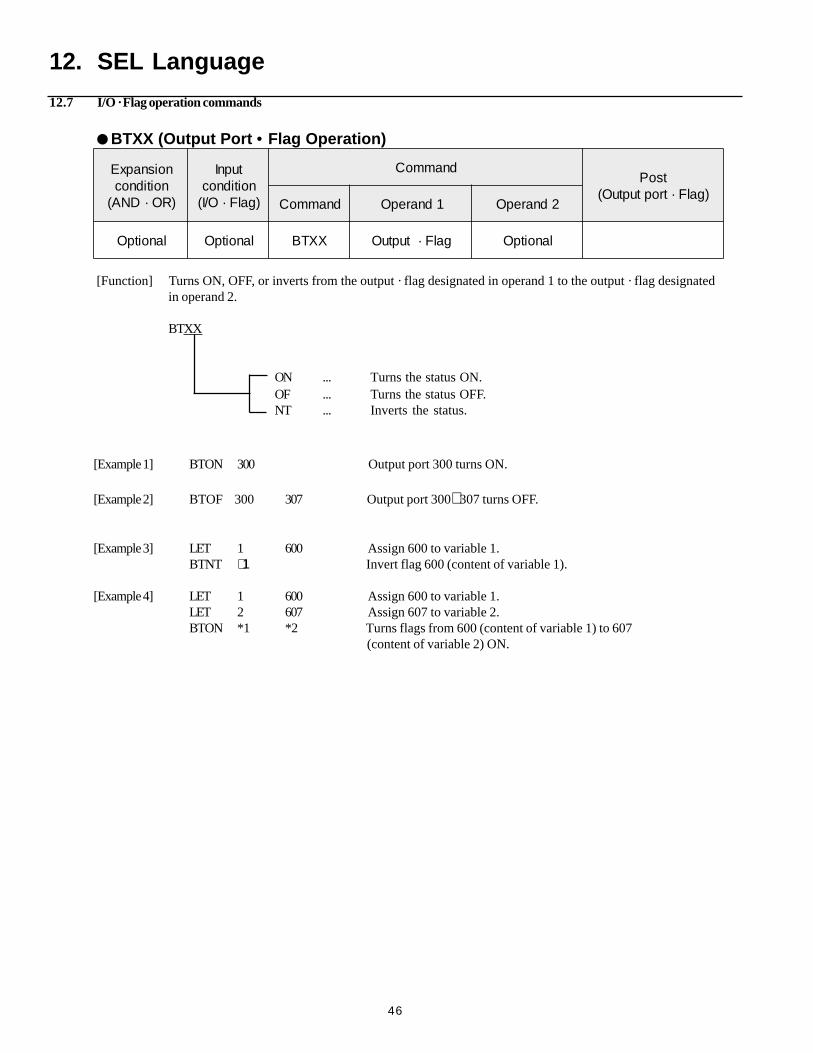
[Function] Turns ON, OFF, or inverts from the output · flag designated in operand 1 to the output · flag designatedin operand 2.
BTXX
noisnapxEnoitidnoc
)RO·DNA(
tupnInoitidnoc)galF·O/I(
dnammoCtsoP
)galF·troptuptuO(dnammoC 1dnarepO 2dnarepO
lanoitpO lanoitpO XXTB galF·tuptuO lanoitpO
BTXX (Output Port • Flag Operation)
ON ... Turns the status ON.OF ... Turns the status OFF.NT ... Inverts the status.
[Example 1] BTON 300 Output port 300 turns ON.
[Example 2] BTOF 300 307 Output port 300∼ 307 turns OFF.
[Example 3] LET 1 600 Assign 600 to variable 1.BTNT ∗1 Invert flag 600 (content of variable 1).
[Example 4] LET 1 600 Assign 600 to variable 1.LET 2 607 Assign 607 to variable 2.BTON *1 *2 Turns flags from 600 (content of variable 1) to 607
(content of variable 2) ON.
12.7 I/O · Flag operation commands
47
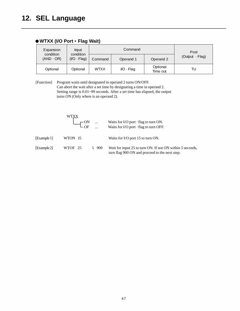
[Function] Program waits until designated in operand 2 turns ON/OFF.Can abort the wait after a set time by designating a time in operand 2.Setting range is 0.01~99 seconds. After a set time has elapsed, the outputturns ON (Only where is an operand 2).
WTXX
ON ... Waits for I/O port · flag to turn ON. OF ... Waits for I/O port · flag to turn OFF.
[Example 1] WTON 15 Waits for I/O port 15 to turn ON.
[Example 2] WTOF 25 5 900 Wait for input 25 to turn ON. If not ON within 5 seconds, turn flag 900 ON and proceed to the next step.
noisnapxEnoitidnoc
)RO·DNA(
tupnInoitidnoc)galF·O/I(
dnammoCtsoP
)galF·tuptuO(dnammoC 1dnarepO 2dnarepO
lanoitpO lanoitpO XXTW galF·O/IlanoitpOtuoemiT
UT
WTXX (I/O Port • Flag Wait)
12. SEL Language
48
133 • • • • • • • • • • • Variable 99
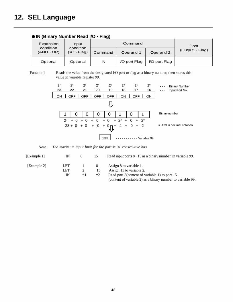
[Function] Reads the value from the designated I/O port or flag as a binary number, then stores thisvalue in variable register 99.
= 133 in decimal notation
• • • Binary Number• • • Input Port No.
noisnapxEnoitidnoc
)RO·DNA(
tupnInoitidnoc)galF·O/I(
dnammoCtsoP
)galF·tuptuO(dnammoC 1dnarepO 2dnarepO
lanoitpO lanoitpO NI galF·tropO/I galF·tropO/I
27 26 25 24 23 22 21 20
32 22 12 02 91 81 71 61
NO FFO FFO FFO FFO NO FFO NO
Note: The maximum input limit for the port is 31 consecutive bits.
[Example 1] IN 8 15 Read input ports 8 ~15 as a binary number in variable 99.
Binary number
12. SEL Language
IN (Binary Number Read I/O • Flag)
[Example 2] LET 1 8 Assign 8 to variable 1. LET 2 15 Assign 15 to variable 2.
IN *1 *2 Read port 8(content of variable 1) to port 15 (content of variable 2) as a binary number to variable 99.
001 0 0 1 0 127 + 0 + 0 + 0 + 0 + 22 + 0 + 20
28 + 0 + 0 + 0 + 0 + 4 + 0 + 2

49
[Function] Reads the BCD value from the designated input port, then stores this value in variable register 99.
noisnapxEnoitidnoc
)RO·DNA(
tupnInoitidnoc)galF·O/I(
dnammoCtsoP
)galF·tuptuO(dnammoC 1dnarepO 2dnarepO
lanoitpO lanoitpO BNI troptupnIfo.oN
stigidDCB
Note 2: The I/O Port • Flag used is 4 x n (number of digits).
[Example 1] INB 8 2 Read input port from 8 for 2 digits (up to 15) as a binary numberto variable 99.
[Example 2 ] LET 1 8 Assign 8 to variable 1.LET 2 2 Assign 2 to variable 2.
IN *1 *2 Read from input port 8 (content of variable 1) for 2 digits(content of variable 2)(up to 15) as a BCD value to variable 99.
12. SEL Language
INB (BCD Read I/O • Flag)
14 13 12 11 10 9 815
ON OFF OFF OFF OFF ON OFF ON
Upper digits Lower digits
Note 1: The maximum number of digits that can be input is 8 (32 bits).
⇓⇓⇓⇓⇓ ••• Input port No.
133 • • • • • • • • • Variable 99
50
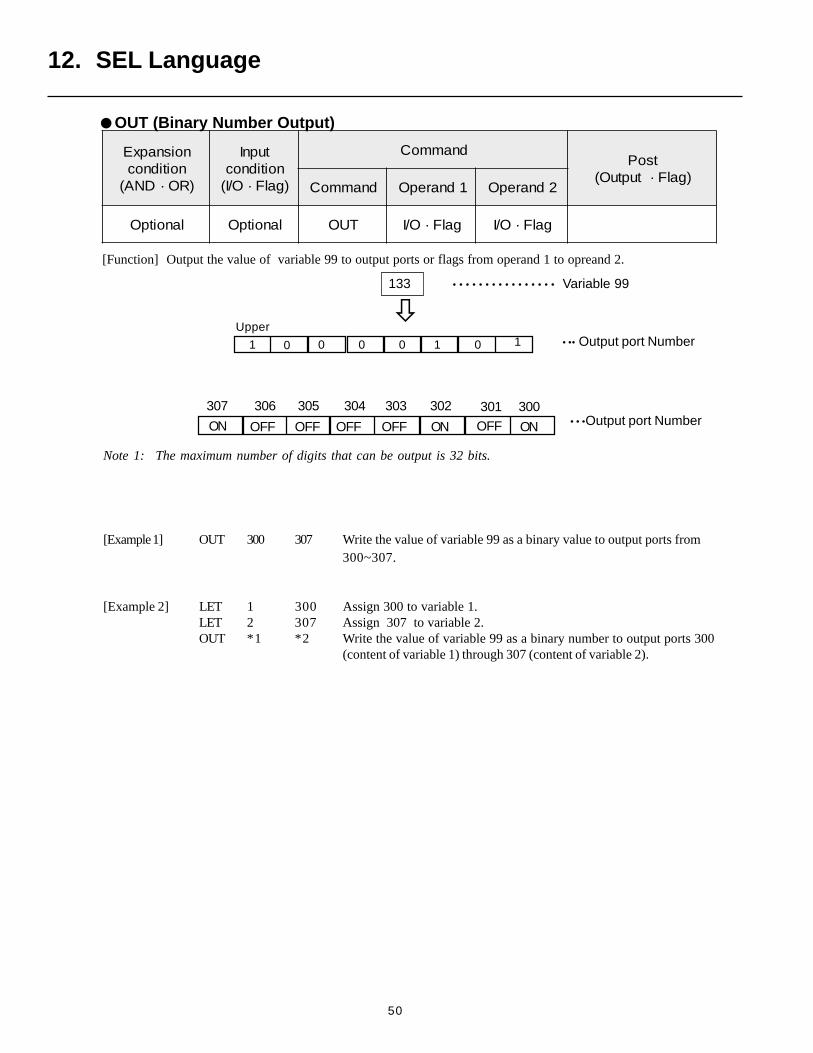
[Function] Output the value of variable 99 to output ports or flags from operand 1 to opreand 2.
Note 1: The maximum number of digits that can be output is 32 bits.
[Example 1] OUT 300 307 Write the value of variable 99 as a binary value to output ports from300~307.
[Example 2] LET 1 300 Assign 300 to variable 1.LET 2 307 Assign 307 to variable 2.OUT *1 *2 Write the value of variable 99 as a binary number to output ports 300
(content of variable 1) through 307 (content of variable 2).
noisnapxEnoitidnoc
)RO·DNA(
tupnInoitidnoc)galF·O/I(
dnammoCtsoP
)galF·tuptuO(dnammoC 1dnarepO 2dnarepO
lanoitpO lanoitpO TUO galF·O/I galF·O/I
133 • • • • • • • • • • • • • • • • Variable 99
12. SEL Language
OUT (Binary Number Output)
• • •Output port NumberON OFF OFF OFF OFF OFFON ON
307 306 305 304 303 302 301 300
Upper
1 0 0 0 0 0 1 • •• Output port Number1
51
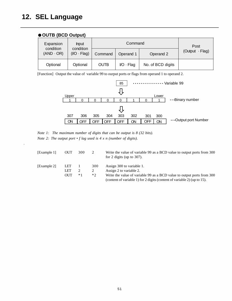
[Function] Output the value of variable 99 to ourput ports or flags from operand 1 to operand 2.
Note 1: The maximum number of digits that can be output is 8 (32 bits).
Note 2: The output port • f lag used is 4 x n (number of digits)..
[Example 1] OUT 300 2 Write the value of variable 99 as a BCD value to output ports from 300for 2 digits (up to 307).
[Example 2] LET 1 300 Assign 300 to variable 1.LET 2 2 Assign 2 to variable 2.OUT *1 *2 Write the value of variable 99 as a BCD value to output ports from 300
(content of variable 1) for 2 digits (content of variable 2) (up to 15).
noisnapxEnoitidnoc
)RO·DNA(
tupnInoitidnoc)galF·O/I(
dnammoCtsoP
)galF·tuptuO(dnammoC 1dnarepO 2dnarepO
lanoitpO lanoitpO BTUO galF·O/I stigidDCBfo.oN
85 • • • • • • • • • • • • • • • • Variable 99
reppU rewoL1 0 0 0 0 1 0 1 • • •Binary number
12. SEL Language
OUTB (BCD Output)
• • •Output port NumberON OFF OFF OFF OFF OFFON ON
307 306 305 304 303 302 301 300
52
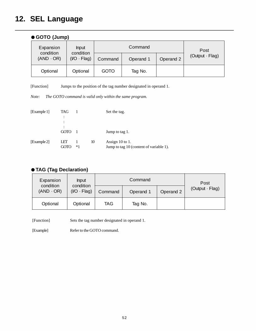
[Function] Sets the tag number designated in operand 1.
[Example] Refer to the GOTO command.
12. SEL Language
TAG (Tag Declaration)
GOTO (Jump)
noisnapxEnoitidnoc
)RO·DNA(
tupnInoitidnoc)galF·O/I(
dnammoCtsoP
)galF·tuptuO(dnammoC 1dnarepO 2dnarepO
lanoitpO lanoitpO OTOG .oNgaT
noisnapxEnoitidnoc
)RO·DNA(
tupnInoitidnoc)galF·O/I(
dnammoCtsoP
)galF·tuptuO(dnammoC 1dnarepO 2dnarepO
lanoitpO lanoitpO GAT .oNgaT
[Function] Jumps to the position of the tag number designated in operand 1.
Note: The GOTO command is valid only within the same program.
[Example 1] TAG 1 Set the tag. : : :GOTO 1 Jump to tag 1.
[Example 2] LET 1 10 Assign 10 to 1.GOTO *1 Jump to tag 10 (content of variable 1).
53
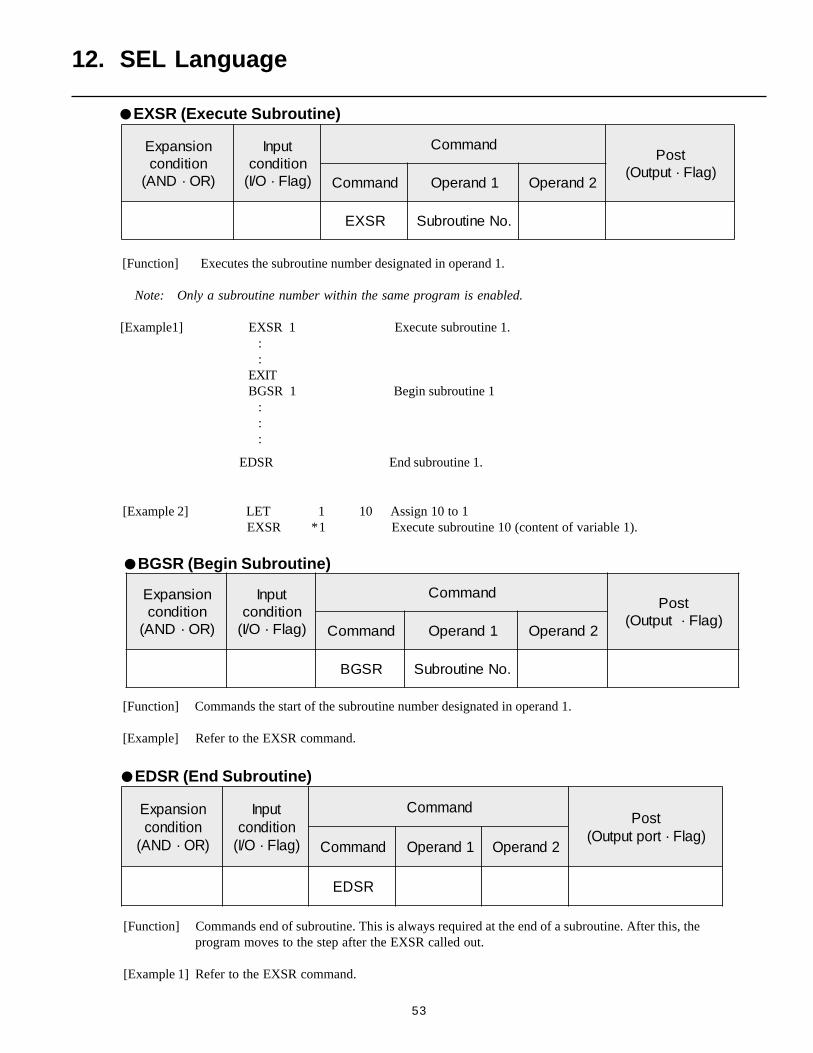
[Function] Commands end of subroutine. This is always required at the end of a subroutine. After this, theprogram moves to the step after the EXSR called out.
[Example 1] Refer to the EXSR command.
[Function] Commands the start of the subroutine number designated in operand 1.
[Example] Refer to the EXSR command.
noisnapxEnoitidnoc
)RO·DNA(
tupnInoitidnoc)galF·O/I(
dnammoCtsoP
)galF·tuptuO(dnammoC 1dnarepO 2dnarepO
RSGB .oNenituorbuS
noisnapxEnoitidnoc
)RO·DNA(
tupnInoitidnoc)galF·O/I(
dnammoCtsoP
)galF·troptuptuO(dnammoC 1dnarepO 2dnarepO
RSDE
[Function] Executes the subroutine number designated in operand 1.
Note: Only a subroutine number within the same program is enabled.
[Example1] EXSR 1 Execute subroutine 1. : :EXITBGSR 1 Begin subroutine 1 : : :
EDSR End subroutine 1.
[Example 2] LET 1 10 Assign 10 to 1 EXSR *1 Execute subroutine 10 (content of variable 1).
12. SEL Language
BGSR (Begin Subroutine)
EDSR (End Subroutine)
EXSR (Execute Subroutine)
noisnapxEnoitidnoc
)RO·DNA(
tupnInoitidnoc)galF·O/I(
dnammoCtsoP
)galF·tuptuO(dnammoC 1dnarepO 2dnarepO
RSXE .oNenituorbuS
54
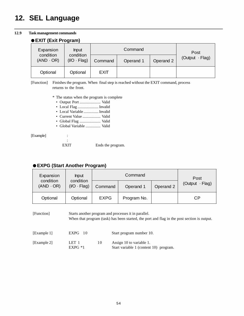
[Function] Starts another program and processes it in parallel.When that program (task) has been started, the port and flag in the post section is output.
[Example 1] EXPG 10 Start program number 10.
[Example 2] LET 1 10 Assign 10 to variable 1.EXPG *1 Start variable 1 (content 10) program.
[Function] Finishes the program. When final step is reached without the EXIT command, processreturns to the front.
* The status when the program is complete• Output Port ..................... Valid• Local Flag ..................... Invalid• Local Variable ............... Invalid• Current Value .................. Valid• Global Flag ..................... Valid• Global Variable ............... Valid
[Example] ::
EXIT Ends the program.
12. SEL Language
EXIT (Exit Program)
noisnapxEnoitidnoc
)RO·DNA(
tupnInoitidnoc)galF·O/I(
dnammoCtsoP
)galF·tuptuO(dnammoC 1dnarepO 2dnarepO
lanoitpO lanoitpO TIXE
noisnapxEnoitidnoc
)RO·DNA(
tupnInoitidnoc)galF·O/I(
dnammoCtsoP
)galF·tuptuO(dnammoC 1dnarepO 2dnarepO
lanoitpO lanoitpO GPXE .oNmargorP PC
EXPG (Start Another Program)
12.9 Task management commands
55
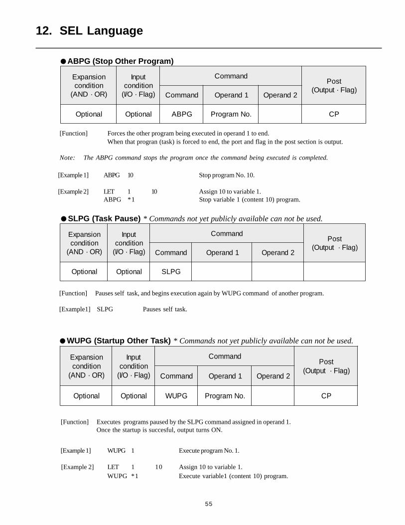
[Function] Executes programs paused by the SLPG command assigned in operand 1.Once the startup is succesful, output turns ON.
[Function] Pauses self task, and begins execution again by WUPG command of another program.
[Example1] SLPG Pauses self task.
noisnapxEnoitidnoc
)RO·DNA(
tupnInoitidnoc)galF·O/I(
dnammoCtsoP
)galF·tuptuO(dnammoC 1dnarepO 2dnarepO
lanoitpO lanoitpO GPLS
noisnapxEnoitidnoc
)RO·DNA(
tupnInoitidnoc)galF·O/I(
dnammoCtsoP
)galF·tuptuO(dnammoC 1dnarepO 2dnarepO
lanoitpO lanoitpO GPUW .oNmargorP PC
[Example 1] ABPG 10 Stop program No. 10.
[Example 2] LET 1 10 Assign 10 to variable 1.ABPG *1 Stop variable 1 (content 10) program.
12. SEL Language
SLPG (Task Pause) * Commands not yet publicly available can not be used.
ABPG (Stop Other Program)
noisnapxEnoitidnoc
)RO·DNA(
tupnInoitidnoc)galF·O/I(
dnammoCtsoP
)galF·tuptuO(dnammoC 1dnarepO 2dnarepO
lanoitpO lanoitpO GPBA .oNmargorP PC
[Function] Forces the other program being executed in operand 1 to end.When that progran (task) is forced to end, the port and flag in the post section is output.
Note: The ABPG command stops the program once the command being executed is completed.
[Example 1] WUPG 1 Execute program No. 1.
[Example 2] LET 1 10 Assign 10 to variable 1.WUPG *1 Execute variable1 (content 10) program.
WUPG (Startup Other Task) * Commands not yet publicly available can not be used.
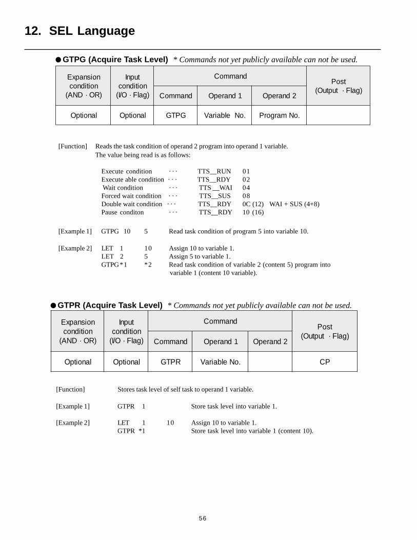
56
[Function] Stores task level of self task to operand 1 variable.
[Example 1] GTPR 1 Store task level into variable 1.
[Example 2] LET 1 10 Assign 10 to variable 1.GTPR *1 Store task level into variable 1 (content 10).
[Function] Reads the task condition of operand 2 program into operand 1 variable.The value being read is as follows:
Execute condition · · · TTS__RUN 01Execute able condition · · · TTS__RDY 02
Wait condition · · · TTS __WAI 04Forced wait condition · · · TTS__SUS 08Double wait condition · · · TTS__RDY 0C (12) WAI + SUS (4+8)Pause conditon · · · TTS__RDY 10 (16)
[Example 1] GTPG 10 5 Read task condition of program 5 into variable 10.
[Example 2] LET 1 10 Assign 10 to variable 1.LET 2 5 Assign 5 to variable 1.GTPG*1 *2 Read task condition of variable 2 (content 5) program into
variable 1 (content 10 variable).
GTPR (Acquire Task Level) * Commands not yet publicly available can not be used.
12. SEL Language
noisnapxEnoitidnoc
)RO·DNA(
tupnInoitidnoc)galF·O/I(
dnammoCtsoP
)galF·tuptuO(dnammoC 1dnarepO 2dnarepO
lanoitpO lanoitpO GPTG .oNelbairaV .oNmargorP
GTPG (Acquire Task Level) * Commands not yet publicly available can not be used.
noisnapxEnoitidnoc
)RO·DNA(
tupnInoitidnoc)galF·O/I(
dnammoCtsoP
)galF·tuptuO(dnammoC 1dnarepO 2dnarepO
lanoitpO lanoitpO RPTG .oNelbairaV PC
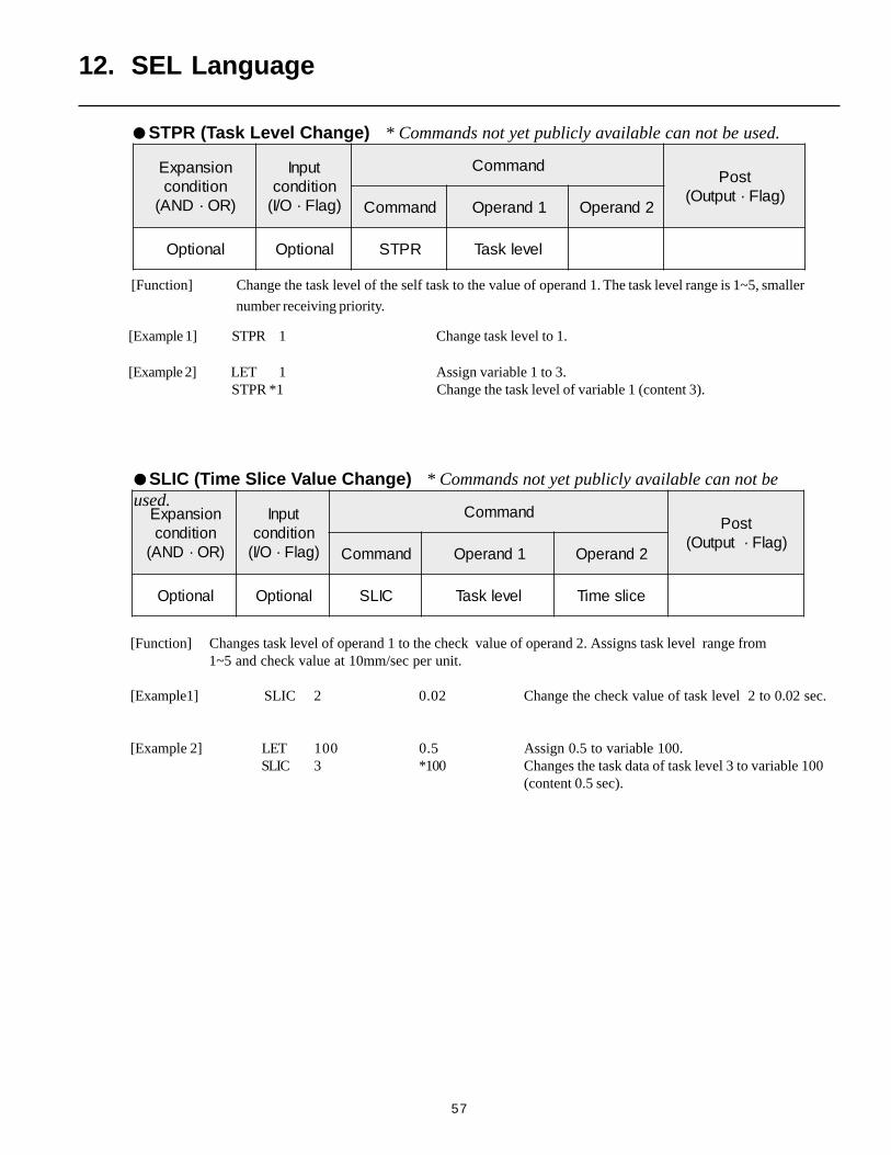
57
[Function] Changes task level of operand 1 to the check value of operand 2. Assigns task level range from1~5 and check value at 10mm/sec per unit.
[Example1] SLIC 2 0.02 Change the check value of task level 2 to 0.02 sec.
[Example 2] LET 100 0.5 Assign 0.5 to variable 100.SLIC 3 *100 Changes the task data of task level 3 to variable 100
(content 0.5 sec).
noisnapxEnoitidnoc
)RO·DNA(
tupnInoitidnoc)galF·O/I(
dnammoCtsoP
)galF·tuptuO(dnammoC 1dnarepO 2dnarepO
lanoitpO lanoitpO CILS levelksaT ecilsemiT
[Example 1] STPR 1 Change task level to 1.
[Example 2] LET 1 Assign variable 1 to 3. STPR *1 Change the task level of variable 1 (content 3).
12. SEL Language
SLIC (Time Slice Value Change) * Commands not yet publicly available can not beused.
STPR (Task Level Change) * Commands not yet publicly available can not be used.
noisnapxEnoitidnoc
)RO·DNA(
tupnInoitidnoc)galF·O/I(
dnammoCtsoP
)galF·tuptuO(dnammoC 1dnarepO 2dnarepO
lanoitpO lanoitpO RPTS levelksaT
[Function] Change the task level of the self task to the value of operand 1. The task level range is 1~5, smaller
number receiving priority.
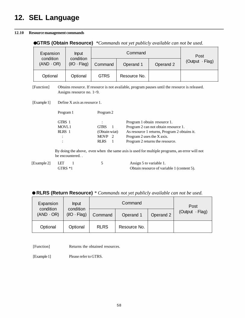
58
[Function] Returns the obtained resources.
[Example 1] Please refer to GTRS.
[Function] Obtains resource. If resource is not available, program pauses until the resource is released.Assigns resource no. 1~9.
[Example 1] Define X axis as resource 1.
Program 1 Program 2
GTRS 1 : Program 1 obtain resource 1.MOVL 1 GTRS 1 Program 2 can not obtain resource 1.RLRS 1 (Obtain wiat) As resource 1 returns, Program 2 obtains it.
: MOVP 2 Program 2 uses the X axis. : RLRS 1 Program 2 returns the resource.
By doing the above, even when the same axis is used for multiple programs, an error will not be encountered. .
RLRS (Return Resource) * Commands not yet publicly available can not be used.
12. SEL Language
noisnapxEnoitidnoc
)RO·DNA(
tupnInoitidnoc)galF·O/I(
dnammoCtsoP
)galF·tuptuO(dnammoC 1dnarepO 2dnarepO
lanoitpO lanoitpO SRTG .oNecruoseR
GTRS (Obtain Resource) *Commands not yet publicly available can not be used.
noisnapxEnoitidnoc
)RO·DNA(
tupnInoitidnoc)galF·O/I(
dnammoCtsoP
)galF·tuptuO(dnammoC 1dnarepO 2dnarepO
lanoitpO lanoitpO SRLR .oNecruoseR
12.10 Resource management commands
[Example 2] LET 1 5 Assign 5 to variable 1.GTRS *1 Obtain resource of variable 1 (content 5).
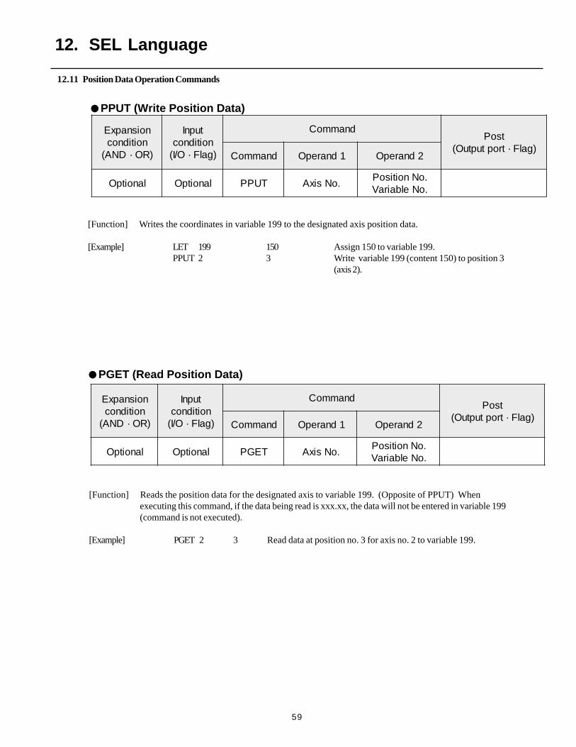
59
12.11 Position Data Operation Commands
[Function] Reads the position data for the designated axis to variable 199. (Opposite of PPUT) Whenexecuting this command, if the data being read is xxx.xx, the data will not be entered in variable 199(command is not executed).
[Example] PGET 2 3 Read data at position no. 3 for axis no. 2 to variable 199.
[Function] Writes the coordinates in variable 199 to the designated axis position data.
[Example] LET 199 150 Assign 150 to variable 199.PPUT 2 3 Write variable 199 (content 150) to position 3
(axis 2).
noisnapxEnoitidnoc
)RO·DNA(
tupnInoitidnoc)galF·O/I(
dnammoCtsoP
)galF·troptuptuO(dnammoC 1dnarepO 2dnarepO
lanoitpO lanoitpO TUPP .oNsixA.oNnoitisoP.oNelbairaV
noisnapxEnoitidnoc
)RO·DNA(
tupnInoitidnoc)galF·O/I(
dnammoCtsoP
)galF·troptuptuO(dnammoC 1dnarepO 2dnarepO
lanoitpO lanoitpO TEGP .oNsixA.oNnoitisoP.oNelbairaV
12. SEL Language
PPUT (Write Position Data)
PGET (Read Position Data)
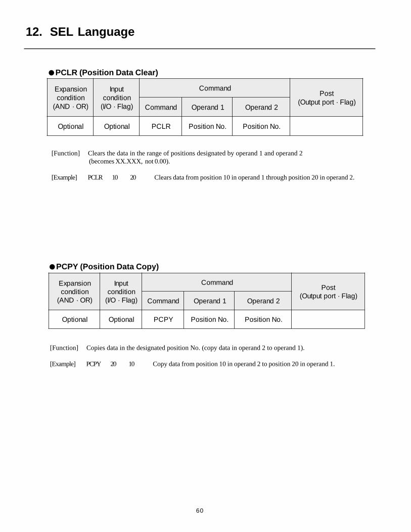
60
12. SEL Language
[Function] Copies data in the designated position No. (copy data in operand 2 to operand 1).
[Example] PCPY 20 10 Copy data from position 10 in operand 2 to position 20 in operand 1.
noisnapxEnoitidnoc
)RO·DNA(
tupnInoitidnoc)galF·O/I(
dnammoCtsoP
)galF·troptuptuO(dnammoC 1dnarepO 2dnarepO
lanoitpO lanoitpO YPCP .oNnoitisoP .oNnoitisoP
[Function] Clears the data in the range of positions designated by operand 1 and operand 2 (becomes XX.XXX, not 0.00).
[Example] PCLR 10 20 Clears data from position 10 in operand 1 through position 20 in operand 2.
noisnapxEnoitidnoc
)RO·DNA(
tupnInoitidnoc)galF·O/I(
dnammoCtsoP
)galF·troptuptuO(dnammoC 1dnarepO 2dnarepO
lanoitpO lanoitpO RLCP .oNnoitisoP .oNnoitisoP
PCPY (Position Data Copy)
PCLR (Position Data Clear)
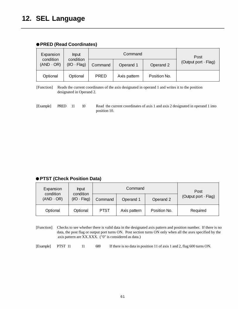
61
[Function] Reads the current coordinates of the axis designated in operand 1 and writes it to the positiondesignated in Operand 2.
[Example] PRED 11 10 Read the current coordinates of axis 1 and axis 2 designated in operand 1 intoposition 10.
noisnapxEnoitidnoc
)RO·DNA(
tupnInoitidnoc)galF·O/I(
dnammoCtsoP
)galF·troptuptuO(dnammoC 1dnarepO 2dnarepO
lanoitpO lanoitpO DERP nrettapsixA .oNnoitisoP
12. SEL Language
noisnapxEnoitidnoc
)RO·DNA(
tupnInoitidnoc)galF·O/I(
dnammoCtsoP
)galF·troptuptuO(dnammoC 1dnarepO 2dnarepO
lanoitpO lanoitpO TSTP nrettapsixA .oNnoitisoP deriuqeR
PTST (Check Position Data)
[Function] Checks to see whether there is valid data in the designated axis pattern and position number. If there is nodata, the post flag or output port turns ON. Post section turns ON only when all the axes specified by the axis pattern are XX.XXX. ("0" is considered as data.)
[Example] PTST 11 11 600 If there is no data in position 11 of axis 1 and 2, flag 600 turns ON.
PRED (Read Coordinates)
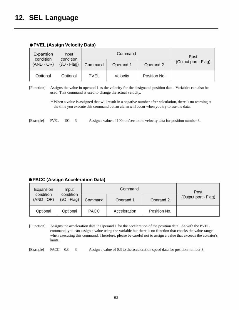
62
12. SEL Language
PVEL (Assign Velocity Data)
[Function] Assigns the value in operand 1 as the velocity for the designated position data. Variables can also beused. This command is used to change the actual velocity.
* When a value is assigned that will result in a negative number after calculation, there is no warning at the time you execute this command but an alarm will occur when you try to use the data.
[Example] PVEL 100 3 Assign a value of 100mm/sec to the velocity data for position number 3.
noisnapxEnoitidnoc
)RO·DNA(
tupnInoitidnoc)galF·O/I(
dnammoCtsoP
)galF·troptuptuO(dnammoC 1dnarepO 2dnarepO
lanoitpO lanoitpO LEVP yticoleV .oNnoitisoP
[Function] Assigns the acceleration data in Operand 1 for the acceleration of the position data. As with the PVELcommand, you can assign a value using the variable but there is no function that checks the value rangewhen executing this command. Therefore, please be careful not to assign a value that exceeds the actuator'slimits.
[Example] PACC 0.3 3 Assign a value of 0.3 to the acceleration speed data for position number 3.
noisnapxEnoitidnoc
)RO·DNA(
tupnInoitidnoc)galF·O/I(
dnammoCtsoP
)galF·troptuptuO(dnammoC 1dnarepO 2dnarepO
lanoitpO lanoitpO CCAP noitareleccA .oNnoitisoP
PACC (Assign Acceleration Data)
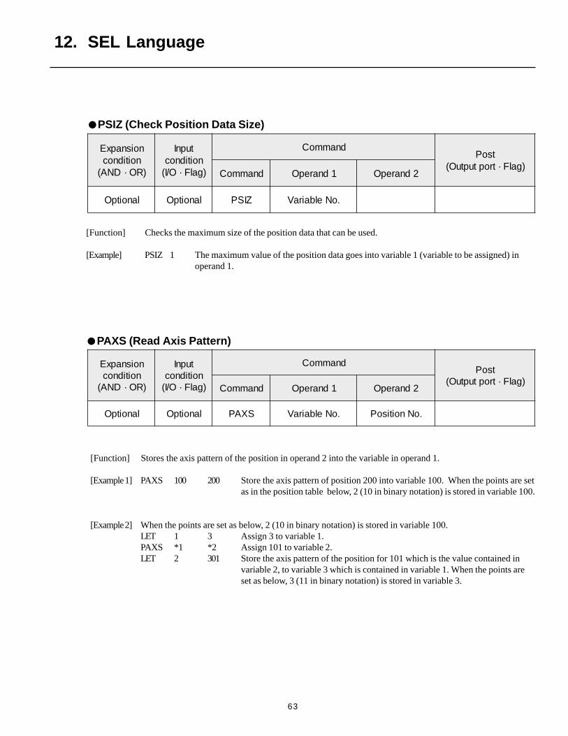
63
12. SEL Language
PSIZ (Check Position Data Size)
[Function] Checks the maximum size of the position data that can be used.
[Example] PSIZ 1 The maximum value of the position data goes into variable 1 (variable to be assigned) inoperand 1.
[Function] Stores the axis pattern of the position in operand 2 into the variable in operand 1.
[Example 1] PAXS 100 200 Store the axis pattern of position 200 into variable 100. When the points are setas in the position table below, 2 (10 in binary notation) is stored in variable 100.
[Example 2] When the points are set as below, 2 (10 in binary notation) is stored in variable 100.LET 1 3 Assign 3 to variable 1.PAXS *1 *2 Assign 101 to variable 2.LET 2 301 Store the axis pattern of the position for 101 which is the value contained in
variable 2, to variable 3 which is contained in variable 1. When the points areset as below, 3 (11 in binary notation) is stored in variable 3.
noisnapxEnoitidnoc
)RO·DNA(
tupnInoitidnoc)galF·O/I(
dnammoCtsoP
)galF·troptuptuO(dnammoC 1dnarepO 2dnarepO
lanoitpO lanoitpO SXAP .oNelbairaV .oNnoitisoP
PAXS (Read Axis Pattern)
noisnapxEnoitidnoc
)RO·DNA(
tupnInoitidnoc)galF·O/I(
dnammoCtsoP
)galF·troptuptuO(dnammoC 1dnarepO 2dnarepO
lanoitpO lanoitpO ZISP .oNelbairaV
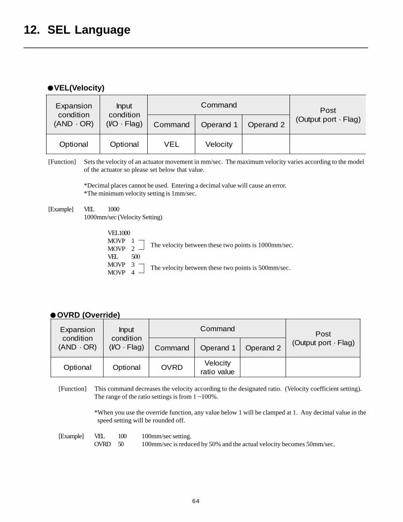
64
OVRD (Override)
[Function] This command decreases the velocity according to the designated ratio. (Velocity coefficient setting).The range of the ratio settings is from 1 ~100%.
*When you use the override function, any value below 1 will be clamped at 1. Any decimal value in the speed setting will be rounded off.
[Example] VEL 100 100mm/sec setting.OVRD 50 100mm/sec is reduced by 50% and the actual velocity becomes 50mm/sec.
noisnapxEnoitidnoc
)RO·DNA(
tupnInoitidnoc)galF·O/I(
dnammoCtsoP
)galF·troptuptuO(dnammoC 1dnarepO 2dnarepO
lanoitpO lanoitpO DRVOyticoleVeulavoitar
The velocity between these two points is 1000mm/sec.
The velocity between these two points is 500mm/sec.
[Function] Sets the velocity of an actuator movement in mm/sec. The maximum velocity varies according to the modelof the actuator so please set below that value.
*Decimal places cannot be used. Entering a decimal value will cause an error.*The minimum velocity setting is 1mm/sec.
[Example] VEL 10001000mm/sec (Velocity Setting)
VEL1000MOVP 1MOVP 2VEL 500MOVP 3MOVP 4
noisnapxEnoitidnoc
)RO·DNA(
tupnInoitidnoc)galF·O/I(
dnammoCtsoP
)galF·troptuptuO(dnammoC 1dnarepO 2dnarepO
lanoitpO lanoitpO LEV yticoleV
12. SEL Language
VEL(Velocity)
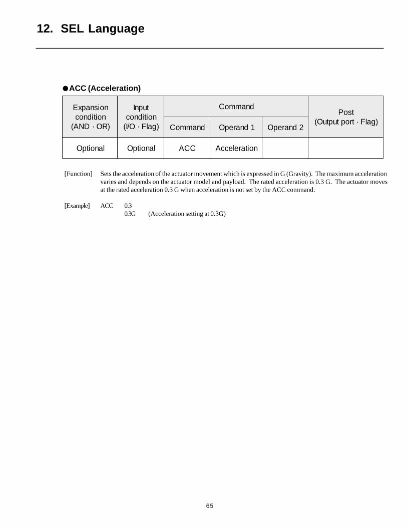
65
12. SEL Language
[Function] Sets the acceleration of the actuator movement which is expressed in G (Gravity). The maximum accelerationvaries and depends on the actuator model and payload. The rated acceleration is 0.3 G. The actuator movesat the rated acceleration 0.3 G when acceleration is not set by the ACC command.
[Example] ACC 0.30.3G (Acceleration setting at 0.3G)
noisnapxEnoitidnoc
)RO·DNA(
tupnInoitidnoc)galF·O/I(
dnammoCtsoP
)galF·troptuptuO(dnammoC 1dnarepO 2dnarepO
lanoitpO lanoitpO CCA noitareleccA
ACC (Acceleration)
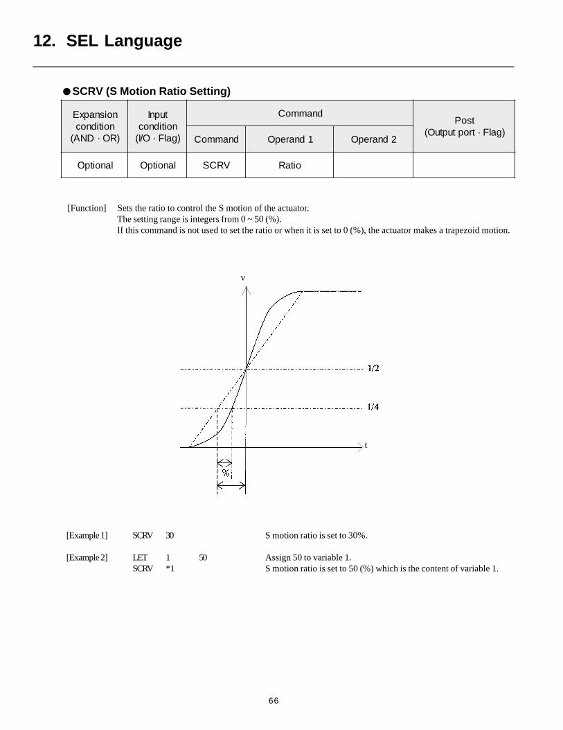
66
[Function] Sets the ratio to control the S motion of the actuator.The setting range is integers from 0 ~ 50 (%).If this command is not used to set the ratio or when it is set to 0 (%), the actuator makes a trapezoid motion.
[Example 1] SCRV 30 S motion ratio is set to 30%.
[Example 2] LET 1 50 Assign 50 to variable 1.SCRV *1 S motion ratio is set to 50 (%) which is the content of variable 1.
noisnapxEnoitidnoc
)RO·DNA(
tupnInoitidnoc)galF·O/I(
dnammoCtsoP
)galF·troptuptuO(dnammoC 1dnarepO 2dnarepO
lanoitpO lanoitpO VRCS oitaR
12. SEL Language
SCRV (S Motion Ratio Setting)
v
t
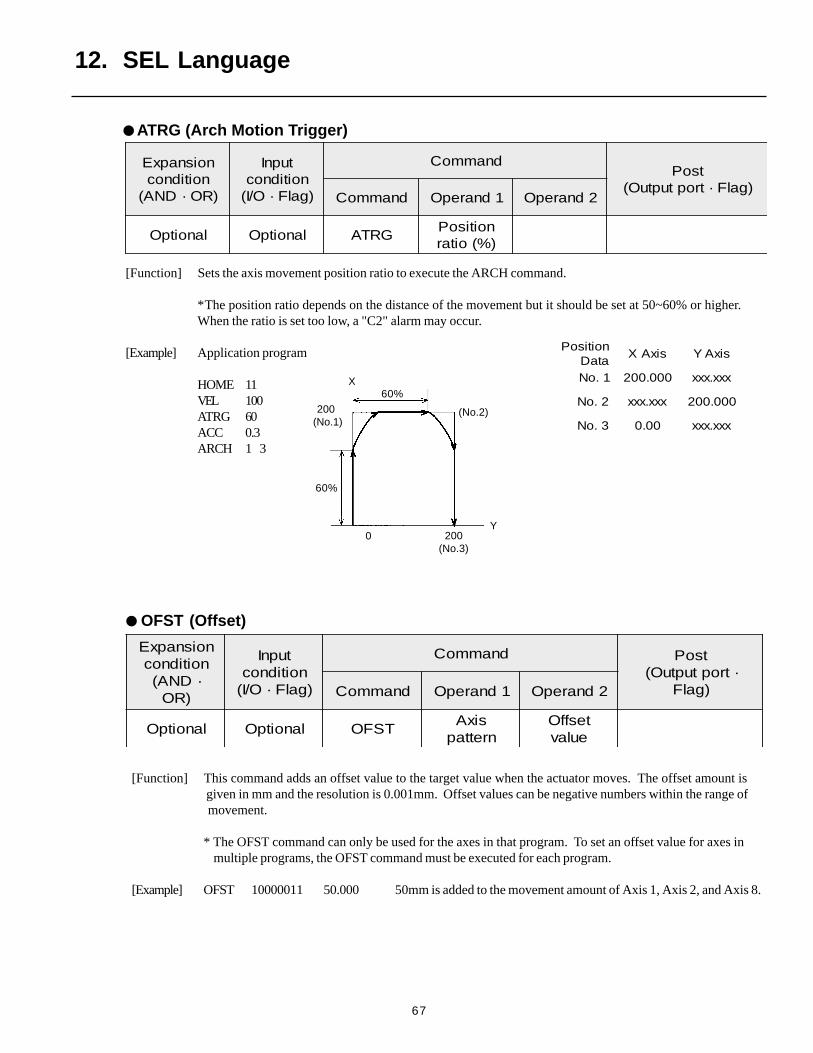
67
60%
200 (No.1)
(No.2)
60%
200(No.3)
0
X
Y
[Function] Sets the axis movement position ratio to execute the ARCH command.
*The position ratio depends on the distance of the movement but it should be set at 50~60% or higher.When the ratio is set too low, a "C2" alarm may occur.
[Example] Application program
HOME 11VEL 100ATRG 60ACC 0.3ARCH 1 3
noisnapxEnoitidnoc
)RO·DNA(
tupnInoitidnoc)galF·O/I(
dnammoCtsoP
)galF·troptuptuO(dnammoC 1dnarepO 2dnarepO
lanoitpO lanoitpO GRTAnoitisoP)%(oitar
noitisoPataD
sixAX sixAY
1.oN 000.002 xxx.xxx
2.oN xxx.xxx 000.002
3.oN 00.0 xxx.xxx
12. SEL Language
OFST (Offset)
[Function] This command adds an offset value to the target value when the actuator moves. The offset amount is given in mm and the resolution is 0.001mm. Offset values can be negative numbers within the range of
movement.
* The OFST command can only be used for the axes in that program. To set an offset value for axes in multiple programs, the OFST command must be executed for each program.
[Example] OFST 10000011 50.000 50mm is added to the movement amount of Axis 1, Axis 2, and Axis 8.
noisnapxEnoitidnoc·DNA(
)RO
tupnInoitidnoc)galF·O/I(
dnammoC tsoP·troptuptuO(
)galFdnammoC 1dnarepO 2dnarepO
lanoitpO lanoitpO TSFOsixA
nrettaptesffO
eulav
ATRG (Arch Motion Trigger)
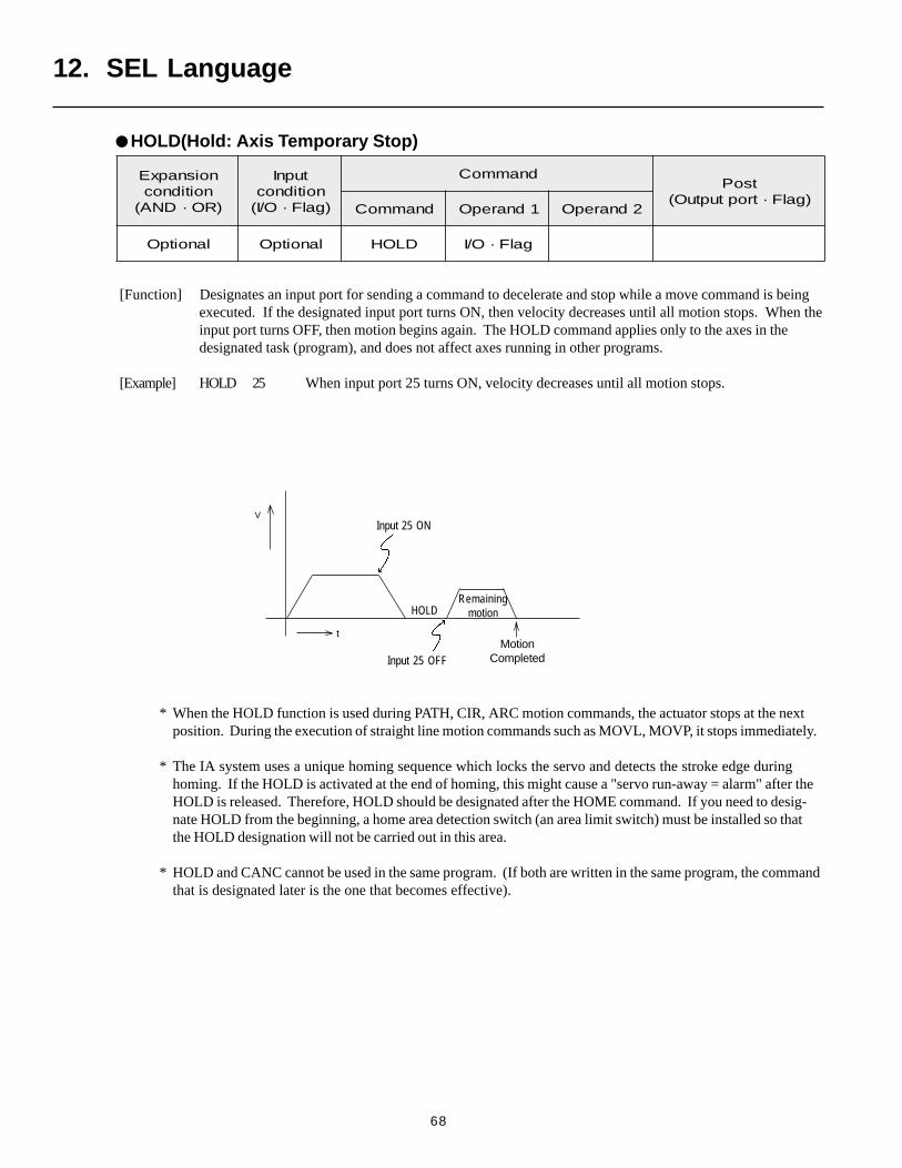
68
Input 25 ON
HOLD
t
Input 25 OFF
V
MotionCompleted
Remainingmotion
[Function] Designates an input port for sending a command to decelerate and stop while a move command is beingexecuted. If the designated input port turns ON, then velocity decreases until all motion stops. When theinput port turns OFF, then motion begins again. The HOLD command applies only to the axes in thedesignated task (program), and does not affect axes running in other programs.
[Example] HOLD 25 When input port 25 turns ON, velocity decreases until all motion stops.
* When the HOLD function is used during PATH, CIR, ARC motion commands, the actuator stops at the nextposition. During the execution of straight line motion commands such as MOVL, MOVP, it stops immediately.
* The IA system uses a unique homing sequence which locks the servo and detects the stroke edge duringhoming. If the HOLD is activated at the end of homing, this might cause a "servo run-away = alarm" after theHOLD is released. Therefore, HOLD should be designated after the HOME command. If you need to desig-nate HOLD from the beginning, a home area detection switch (an area limit switch) must be installed so thatthe HOLD designation will not be carried out in this area.
* HOLD and CANC cannot be used in the same program. (If both are written in the same program, the commandthat is designated later is the one that becomes effective).
noisnapxEnoitidnoc
)RO·DNA(
tupnInoitidnoc)galF·O/I(
dnammoCtsoP
)galF·troptuptuO(dnammoC 1dnarepO 2dnarepO
lanoitpO lanoitpO DLOH galF·O/I
HOLD(Hold: Axis Temporary Stop)
12. SEL Language
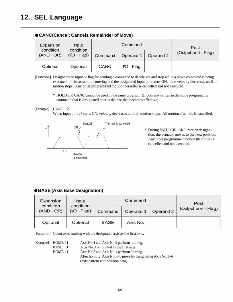
69
[Function] Designates an input or flag for sending a command to decelerate and stop while a move command is beingexecuted. If the actuator is moving and the designated input port turns ON, then velocity decreases until allmotion stops. Any other programmed motion thereafter is cancelled and not executed.
* HOLD and CANC cannot be used in the same program. (If both are written in the same program, thecommand that is designated later is the one that becomes effective).
[Example] CANC 25When input port 25 turns ON, velocity decreases until all motion stops. All motion after this is cancelled.
V
t
Input 25ON
MotionCompleted
The rest is cancelled
* During PATH, CIR, ARC motion designa-tion, the actuator moves to the next position.Any other programmed motion thereafter iscancelled and not executed.
noisnapxEnoitidnoc
)RO·DNA(
tupnInoitidnoc)galF·O/I(
dnammoCtsoP
)galF·troptuptuO(dnammoC 1dnarepO 2dnarepO
lanoitpO lanoitpO CNAC galF·O/I
12. SEL Language
[Function] Count axes starting with the designated axis as the first axis.
[Example] HOME 11 Axis No.1 and Axis No.2 perform homing.BASE 3 Axis No.3 is counted as the first axis.HOME 11 Axis No.3 and Axis No.4 perform homing.
After homing, Axis No.3~8 move by designating Axis No.1~6(axis pattern and position data).
noisnapxEnoitidnoc
)RO·DNA(
tupnInoitidnoc)galF·O/I(
dnammoCtsoP
)galF·troptuptuO(dnammoC 1dnarepO 2dnarepO
lanoitpO lanoitpO ESAB .oNsixA
BASE (Axis Base Designation)
CANC(Cancel: Cancels Remainder of Move)
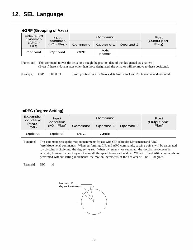
70
[Function] This command moves the actuator through the position data of the designated axis pattern.(Even if there is data in axes other than those designated, the actuator will not move to these positions).
[Example] GRP 00000011 From position data for 8 axes, data from axis 1 and 2 is taken out and executed.
[Function] This command sets up the motion increments for use with CIR (Circular Movement) and ARC(Arc Movement) commands. When performing CIR and ARC commands, passing points will be calculated by dividing a circle into the degrees as set. When increments are set small, the circular movement isaccurate, however, when they are too small, the speed becomes too slow. When CIR and ARC commands areperformed without setting increments, the motion increments of the actuator will be 15 degrees.
[Example] DEG 10
Motion in 10degree increments.
noisnapxEnoitidnoc·DNA(
)RO
tupnInoitidnoc)galF·O/I(
dnammoC tsoP·troptuptuO(
)galFdnammoC 1dnarepO 2dnarepO
lanoitpO lanoitpO PRGsixA
nrettap
noisnapxEnoitidnoc·DNA(
)RO
tupnInoitidnoc)galF·O/I(
dnammoC tsoP·troptuptuO(
)galFdnammoC 1dnarepO 2dnarepO
lanoitpO lanoitpO GED elgnA
12. SEL Language
GRP (Grouping of Axes)
DEG (Degree Setting)
71
12. SEL Language
[Function] Stores the status (error code) of the axis in Operand 2 in the variable in Operand 1.Only error codes that begin with the letter "A" will be stored in the register in Operand 1. These errorcodes are the same ones that are displayed on the front panel of the controller. (The error codes in thetable are written in hexadecimal numbers. The hexadecimal value in the variable in Operand 1 must beconverted to a decimal number to identify its error code.)
[Example] AXST 1 2 Read the status for Axis 2 to variable 1.If 161 was in variable 1, 161 ÷ 16 = 10 ( = A) with a remainder of 1, thenthis means that error code A1 (External Interrupt Error) occurred on Axis 2.
AXST (Axis Status Acquisition)
noisnapxEnoitidnoc
)RO·DNA(
tupnInoitidnoc)galF·O/I(
dnammoCtsoP
)galF·troptuptuO(dnammoC 1dnarepO 2dnarepO
lanoitpO lanoitpO TSXA .oNelbairaV .oNsixA
72
[Function] This commands turns the servo of the designated axes ON/OFF .
SVXX
12.13 Actuator Control Commands
12. SEL Language
SVXX (Servo ON/OFF)
ON • • • Turns the servo ON.
OF • • • Turns the servo OFF.
[Example] SVON SVON 11001100 Turn on the servo for axis 4, 7, 8. This does not affextaxes that are already ON.
[Function] This command executes homing of the designated axes. Servos turn ON automatically.
[Example] HOME 10000011 Axis 1, 2, and 8 axes execute homing.
noisnapxEnoitidnoc
)RO·DNA(
tupnInoitidnoc)galF·O/I(
dnammoCtsoP
)galF·troptuptuO(dnammoC 1dnarepO 2dnarepO
lanoitpO lanoitpO XXVS nrettapsixA
HOME (Return Home)
noisnapxEnoitidnoc
)RO·DNA(
tupnInoitidnoc)galF·O/I(
dnammoCtsoP
)galF·troptuptuO(dnammoC 1dnarepO 2dnarepO
lanoitpO lanoitpO EMOH nrettapsixA lanoitpO

73
[Function] This command moves the actuator to the designated position number from point to point withoutinterpolation.
[Example] MOVP 100Moves to Position No. 100 (point to point).
MOVP *1If variable 1 is 150, then the actuator moves toposition number 150 (point to point).
Each axis moves at itsown designated speed.
noisnapxEnoitidnoc
)RO·DNA(
tupnInoitidnoc)galF·O/I(
dnammoCtsoP
)galF·troptuptuO(dnammoC 1dnarepO 2dnarepO
lanoitpO lanoitpO PVOM .onnoitisoP lanoitpO
noitisoP.oN
1 2 3123
001-0.001
0-0.001
0-x.xxx
x
051-0.002
0-0.002
0-x.xxx
x
Move path when X-axis moves to 200mm point and Y-axis movesto 100mm point from home.
X axis
Y axis motion completeY axis
100mm
200mmHome 0
12. SEL Language
MOVP (Point to-Point Position Data)
MOVD (Direct Designate Move)
noisnapxEnoitidnoc
)RO·DNA(
tupnInoitidnoc)galF·O/I(
dnammoCtsoP
)galF·troptuptuO(dnammoC 1dnarepO 2dnarepO
lanoitpO lanoitpO DVOM noitisopevoM lanoitpO
[Function] Moves the actuator to a position designated in operand 1.Output turns OFF when axis move starts, and upon completion, turns ON.
[Example 1] MOVD 100 Move the axis to position 100.
[Example 2] LET 1 100 Assign 100 to variable 1.MOVD *1 Move the axis to variable 1 (content 100) position.
* Note: This command is applicable to the DS type only.
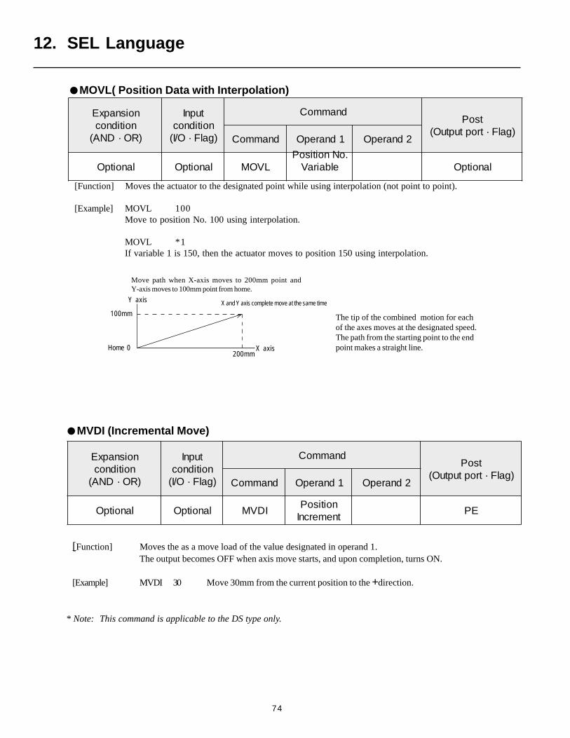
74
[Function] Moves the actuator to the designated point while using interpolation (not point to point).
[Example] MOVL 100Move to position No. 100 using interpolation.
MOVL *1If variable 1 is 150, then the actuator moves to position 150 using interpolation.
noisnapxEnoitidnoc
)RO·DNA(
tupnInoitidnoc)galF·O/I(
dnammoCtsoP
)galF·troptuptuO(dnammoC 1dnarepO 2dnarepO
lanoitpO lanoitpO LVOM.oNnoitisoP
elbairaV lanoitpO
The tip of the combined motion for eachof the axes moves at the designated speed.The path from the starting point to the endpoint makes a straight line.
Move path when X-axis moves to 200mm point andY-axis moves to 100mm point from home.
X and Y axis complete move at the same time
X axis
Y axis
100mm
200mmHome 0
12. SEL Language
MVDI (Incremental Move)
noisnapxEnoitidnoc
)RO·DNA(
tupnInoitidnoc)galF·O/I(
dnammoCtsoP
)galF·troptuptuO(dnammoC 1dnarepO 2dnarepO
lanoitpO lanoitpO IDVMnoitisoPtnemercnI
EP
MOVL( Position Data with Interpolation)
[Function] Moves the as a move load of the value designated in operand 1.The output becomes OFF when axis move starts, and upon completion, turns ON.
[Example] MVDI 30 Move 30mm from the current position to the +direction.
* Note: This command is applicable to the DS type only.
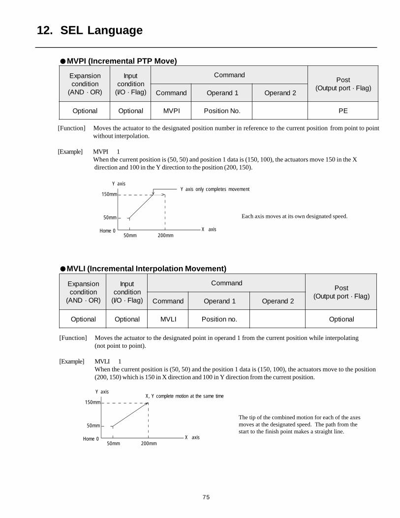
75
[Function] Moves the actuator to the designated point in operand 1 from the current position while interpolating(not point to point).
[Example] MVLI 1When the current position is (50, 50) and the position 1 data is (150, 100), the actuators move to the position(200, 150) which is 150 in X direction and 100 in Y direction from the current position.
[Function] Moves the actuator to the designated position number in reference to the current position from point to pointwithout interpolation.
[Example] MVPI 1When the current position is (50, 50) and position 1 data is (150, 100), the actuators move 150 in the X direction and 100 in the Y direction to the position (200, 150).
noisnapxEnoitidnoc
)RO·DNA(
tupnInoitidnoc)galF·O/I(
dnammoCtsoP
)galF·troptuptuO(dnammoC 1dnarepO 2dnarepO
lanoitpO lanoitpO ILVM .onnoitisoP lanoitpO
Each axis moves at its own designated speed.
Y axis only completes movementY axis
X axisHome 0
50mm
150mm
50mm 200mm
The tip of the combined motion for each of the axesmoves at the designated speed. The path from thestart to the finish point makes a straight line.
Y axis
X axisHome 0
50mm
150mm
50mm 200mm
X, Y complete motion at the same time
noisnapxEnoitidnoc
)RO·DNA(
tupnInoitidnoc)galF·O/I(
dnammoCtsoP
)galF·troptuptuO(dnammoC 1dnarepO 2dnarepO
lanoitpO lanoitpO IPVM .oNnoitisoP EP
MVPI (Incremental PTP Move)
MVLI (Incremental Interpolation Movement)
12. SEL Language
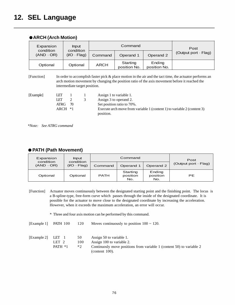
76
noisnapxEnoitidnoc
)RO·DNA(
tupnInoitidnoc)galF·O/I(
dnammoCtsoP
)galF·troptuptuO(dnammoC 1dnarepO 2dnarepO
lanoitpO lanoitpO HCRAgnitratS
.oNnoitisopgnidnE
.oNnoitisop
12. SEL Language
[Function] In order to accomplish faster pick & place motion in the air and the tact time, the actuator performs anarch motion movement by changing the position ratio of the axis movement before it reached theintermediate target position.
[Example] LET 1 1 Assign 1 to variable 1.LET 2 3 Assign 3 to operand 2.ATRG 70 Set position ratio to 70%.ARCH *1 Execute arch move from variable 1 (content 1) to variable 2 (content 3)
position.
[Function] Actuator moves continuously between the designated starting point and the finishing point. The locus isa B-spline-type, free-form curve which passes through the inside of the designated coordinate. It ispossible for the actuator to move close to the designated coordinate by increasing the acceleration.However, when it exceeds the maximum acceleration, an error will occur.
* Three and four axis motion can be performed by this command.
[Example 1] PATH 100 120 Moves continuously to position 100 ~ 120.
[Example 2] LET 1 50 Assign 50 to variable 1.LET 2 100 Assign 100 to variable 2.PATH *1 *2 Continuosly move positions from variable 1 (content 50) to variable 2
(content 100).
noisnapxEnoitidnoc
)RO·DNA(
tupnInoitidnoc)galF·O/I(
dnammoCtsoP
)galF·troptuptuO(dnammoC 1dnarepO 2dnarepO
lanoitpO lanoitpO HTAPgnitratSnoitisop
.oN
gnidnEnoitisop
.oNEP
PATH (Path Movement)
ARCH (Arch Motion)
*Note: See ATRG command
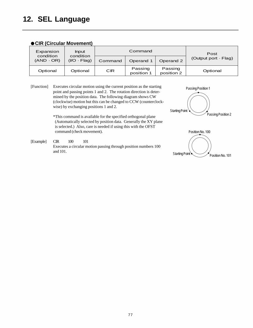
77
[Function] Executes circular motion using the current position as the startingpoint and passing points 1 and 2. The rotation direction is deter-mined by the position data. The following diagram shows CW(clockwise) motion but this can be changed to CCW (counterclock-wise) by exchanging positions 1 and 2.
*This command is available for the specified orthogonal plane(Automatically selected by position data. Generally the XY planeis selected.) Also, care is needed if using this with the OFSTcommand (check movement).
[Example] CIR 100 101Executes a circular motion passing through position numbers 100and 101.
Position No. 101
Position No. 100
Starting Point
Passing Position 1
Passing Position 2
Starting Point
noisnapxEnoitidnoc
)RO·DNA(
tupnInoitidnoc)galF·O/I(
dnammoCtsoP
)galF·troptuptuO(dnammoC 1dnarepO 2dnarepO
lanoitpO lanoitpO RICgnissaP1noitisop
gnissaP2noitisop
lanoitpO
CIR (Circular Movement)
12. SEL Language
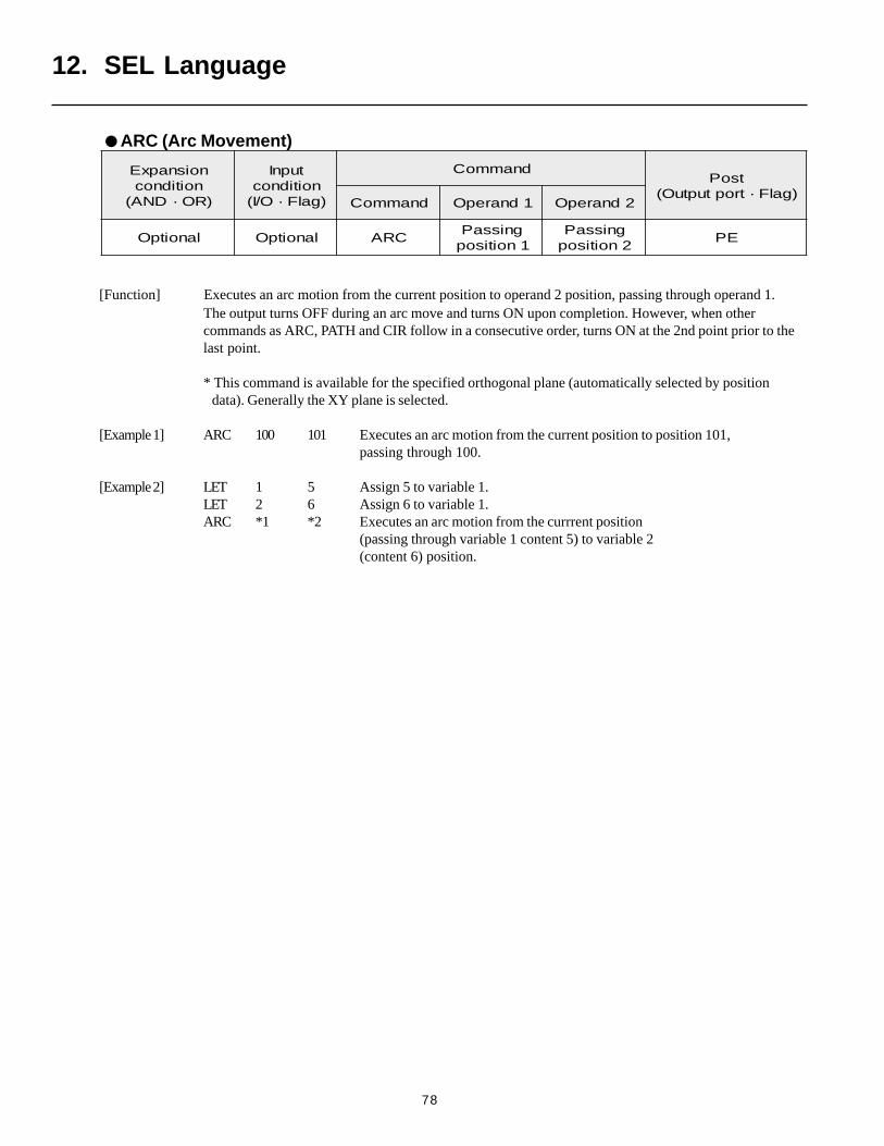
78
noisnapxEnoitidnoc
)RO·DNA(
tupnInoitidnoc)galF·O/I(
dnammoCtsoP
)galF·troptuptuO(dnammoC 1dnarepO 2dnarepO
lanoitpO lanoitpO CRAgnissaP1noitisop
gnissaP2noitisop
EP
ARC (Arc Movement)
12. SEL Language
[Function] Executes an arc motion from the current position to operand 2 position, passing through operand 1.The output turns OFF during an arc move and turns ON upon completion. However, when othercommands as ARC, PATH and CIR follow in a consecutive order, turns ON at the 2nd point prior to thelast point.
* This command is available for the specified orthogonal plane (automatically selected by position data). Generally the XY plane is selected.
[Example 1] ARC 100 101 Executes an arc motion from the current position to position 101,passing through 100.
[Example 2] LET 1 5 Assign 5 to variable 1.LET 2 6 Assign 6 to variable 1.ARC *1 *2 Executes an arc motion from the currrent position
(passing through variable 1 content 5) to variable 2(content 6) position.
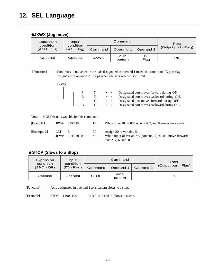
79
noisnapxEnoitidnoc
)RO·DNA(
tupnInoitidnoc)galF·O/I(
dnammoCtsoP
)galF·troptuptuO(dnammoC 1dnarepO 2dnarepO
lanoitpO lanoitpO XWXJsixA
nrettapO/I
galFEP
12. SEL Language
JXWX (Jog move)
[Function] Continues to move while the axis designated in operand 1 meets the condition I/O port flagdesignated in operand 2. Stops when the axis reached soft limit.
JXWX
F N • • • Designated port moves forward during ON.B N • • • Designated port moves backward during ON.F F • • • Designated port moves forward during OFF.B F • • • Designated port moves backward during OFF.
Note: HOLD is not available for this command.
[Example 1] JBWF 11001100 10 While input 10 is OFF, Axis 3, 4, 7, and 8 moves backwards.
[Example 2] LET 5 20 Assign 20 to variable 5.JFWN 10101010 *5 While input of variable 5 (content 20) is ON, move forward
axis 2, 4, 6, and 8.
STOP (Slows to a Stop)
[Function] Axis designated in operand 1 axis pattern slows to a stop.
[Example] STOP 11001100 Axis 3, 4, 7 and 8 Slows to a stop.
noisnapxEnoitidnoc
)RO·DNA(
tupnInoitidnoc)galF·O/I(
dnammoCtsoP
)galF·troptuptuO(dnammoC 1dnarepO 2dnarepO
lanoitpO lanoitpO POTSsixA
nrettapEP
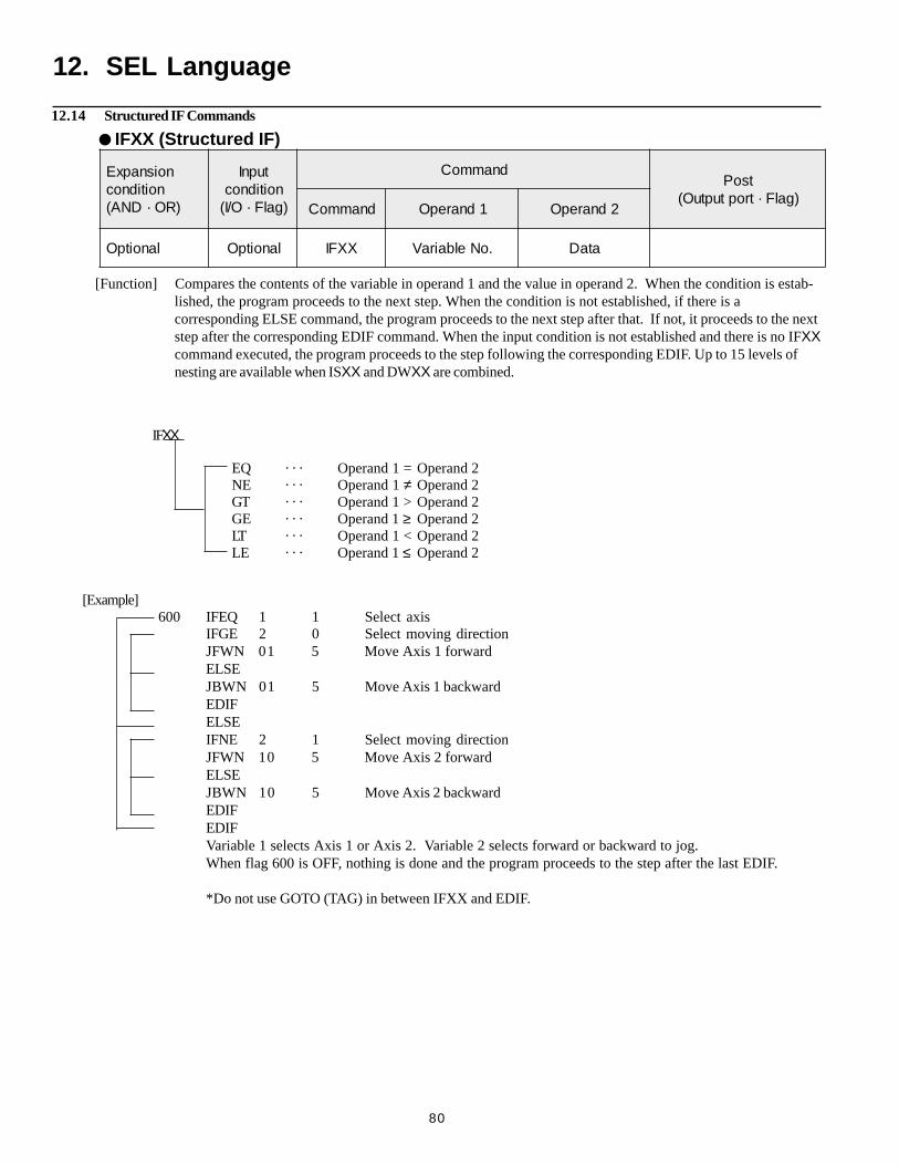
80
12. SEL Language
[Function] Compares the contents of the variable in operand 1 and the value in operand 2. When the condition is estab-lished, the program proceeds to the next step. When the condition is not established, if there is acorresponding ELSE command, the program proceeds to the next step after that. If not, it proceeds to the nextstep after the corresponding EDIF command. When the input condition is not established and there is no IFXXcommand executed, the program proceeds to the step following the corresponding EDIF. Up to 15 levels ofnesting are available when ISXX and DWXX are combined.
12.14 Structured IF Commands
IFXX
EQ · · · Operand 1 = Operand 2NE · · · Operand 1 ≠ Operand 2GT · · · Operand 1 > Operand 2GE · · · Operand 1 ≥ Operand 2LT · · · Operand 1 < Operand 2LE · · · Operand 1 ≤ Operand 2
[Example] 600 IFEQ 1 1 Select axis
IFGE 2 0 Select moving directionJFWN 01 5 Move Axis 1 forwardELSEJBWN 01 5 Move Axis 1 backwardEDIFELSEIFNE 2 1 Select moving directionJFWN 10 5 Move Axis 2 forwardELSEJBWN 10 5 Move Axis 2 backwardEDIFEDIFVariable 1 selects Axis 1 or Axis 2. Variable 2 selects forward or backward to jog.When flag 600 is OFF, nothing is done and the program proceeds to the step after the last EDIF.
*Do not use GOTO (TAG) in between IFXX and EDIF.
IFXX (Structured IF)
noisnapxEnoitidnoc
)RO·DNA(
tupnInoitidnoc)galF·O/I(
dnammoCtsoP
)galF·troptuptuO(dnammoC 1dnarepO 2dnarepO
lanoitpO lanoitpO XXFI .oNelbairaV ataD
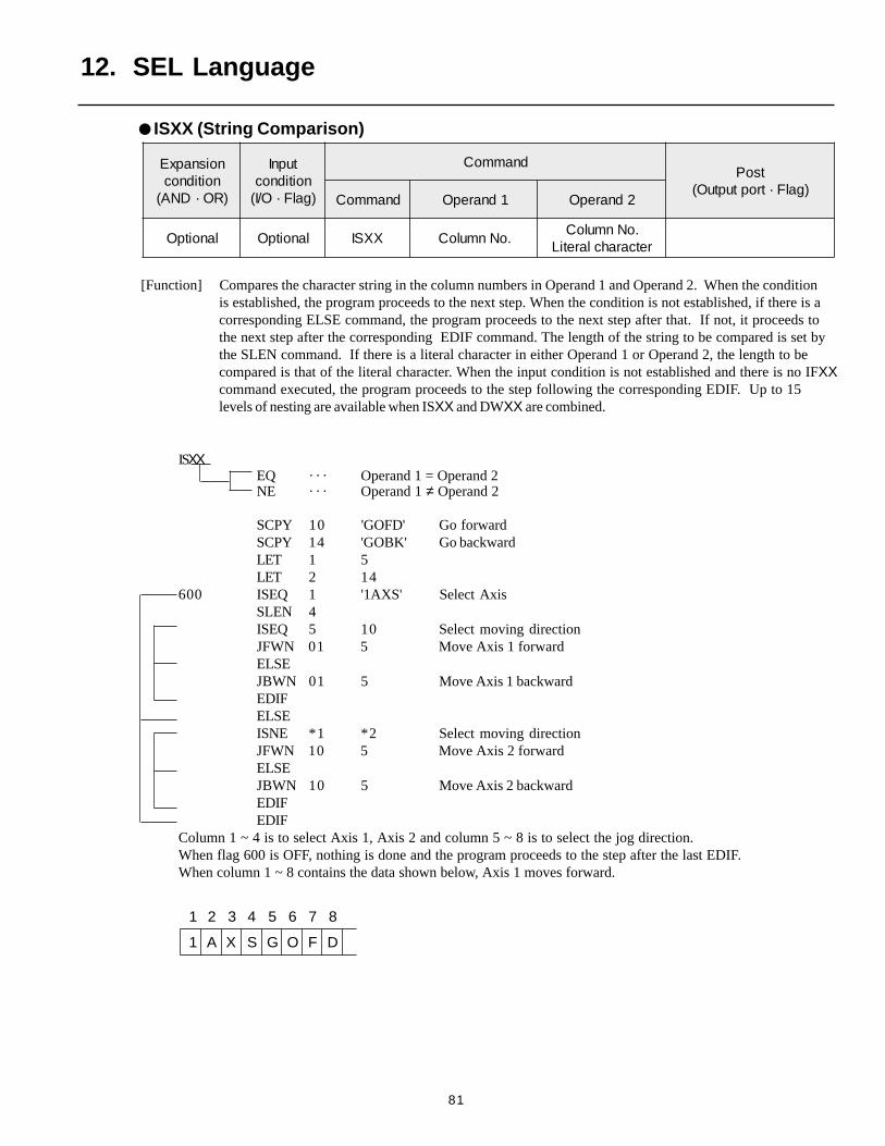
81
ISXX (String Comparison)
[Function] Compares the character string in the column numbers in Operand 1 and Operand 2. When the conditionis established, the program proceeds to the next step. When the condition is not established, if there is acorresponding ELSE command, the program proceeds to the next step after that. If not, it proceeds tothe next step after the corresponding EDIF command. The length of the string to be compared is set bythe SLEN command. If there is a literal character in either Operand 1 or Operand 2, the length to becompared is that of the literal character. When the input condition is not established and there is no IFXXcommand executed, the program proceeds to the step following the corresponding EDIF. Up to 15levels of nesting are available when ISXX and DWXX are combined.
ISXXEQ · · · Operand 1 = Operand 2NE · · · Operand 1 ≠ Operand 2
SCPY 10 'GOFD' Go forwardSCPY 14 'GOBK' Go backwardLET 1 5LET 2 14
600 ISEQ 1 '1AXS' Select AxisSLEN 4ISEQ 5 10 Select moving directionJFWN 01 5 Move Axis 1 forwardELSEJBWN 01 5 Move Axis 1 backwardEDIFELSEISNE *1 *2 Select moving directionJFWN 10 5 Move Axis 2 forwardELSEJBWN 10 5 Move Axis 2 backwardEDIFEDIF
Column 1 ~ 4 is to select Axis 1, Axis 2 and column 5 ~ 8 is to select the jog direction.When flag 600 is OFF, nothing is done and the program proceeds to the step after the last EDIF.When column 1 ~ 8 contains the data shown below, Axis 1 moves forward.
12. SEL Language
noisnapxEnoitidnoc
)RO·DNA(
tupnInoitidnoc)galF·O/I(
dnammoCtsoP
)galF·troptuptuO(dnammoC 1dnarepO 2dnarepO
lanoitpO lanoitpO SI XX .oNnmuloC.oNnmuloC
retcarahclaretiL
1 2 3 4 5 6 7 8
1 A X S G O F D
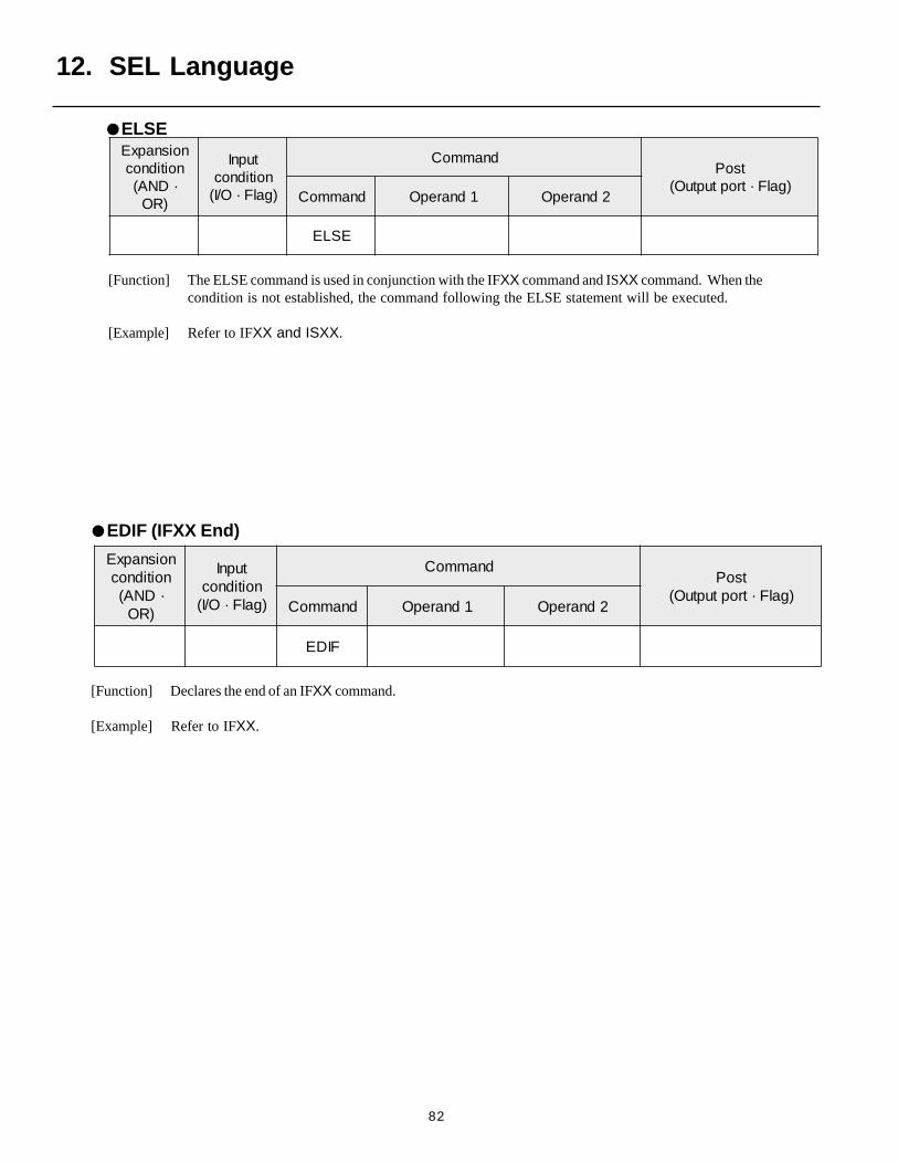
82
[Function] Declares the end of an IFXX command.
[Example] Refer to IFXX.
[Function] The ELSE command is used in conjunction with the IFXX command and ISXX command. When thecondition is not established, the command following the ELSE statement will be executed.
[Example] Refer to IFXX and ISXX.
12. SEL Language
ELSEnoisnapxE
noitidnoc·DNA(
)RO
tupnInoitidnoc)galF·O/I(
dnammoCtsoP
)galF·troptuptuO(dnammoC 1dnarepO 2dnarepO
ESLE
EDIF (IFXX End)
noisnapxEnoitidnoc·DNA(
)RO
tupnInoitidnoc)galF·O/I(
dnammoCtsoP
)galF·troptuptuO(dnammoC 1dnarepO 2dnarepO
FIDE
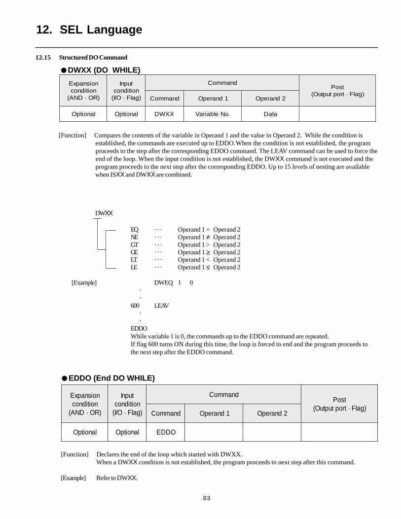
83
[Function] Compares the contents of the variable in Operand 1 and the value in Operand 2. While the condition is established, the commands are executed up to EDDO.When the condition is not established, the program proceeds to the step after the corresponding EDDO command. The LEAV command can be used to force the end of the loop. When the input condition is not established, the DWXX command is not executed and the program proceeds to the next step after the corresponding EDDO. Up to 15 levels of nesting are available when ISXX and DWXX are combined.
12.15 Structured DO Command
noisnapxEnoitidnoc
)RO·DNA(
tupnInoitidnoc)galF·O/I(
dnammoCtsoP
)galF·troptuptuO(dnammoC 1dnarepO 2dnarepO
lanoitpO lanoitpO WD XX .oNelbairaV ataD
DWXX
EQ · · · Operand 1 = Operand 2NE · · · Operand 1 ≠ Operand 2GT · · · Operand 1 > Operand 2GE · · · Operand 1 ≥ Operand 2LT · · · Operand 1 < Operand 2LE · · · Operand 1 ≤ Operand 2
[Example] DWEQ 1 0 · ·600 LEAV · ·EDDOWhile variable 1 is 0, the commands up to the EDDO command are repeated.If flag 600 turns ON during this time, the loop is forced to end and the program proceeds tothe next step after the EDDO command.
12. SEL Language
DWXX (DO WHILE)
noisnapxEnoitidnoc
)RO·DNA(
tupnInoitidnoc)galF·O/I(
dnammoCtsoP
)galF·troptuptuO(dnammoC 1dnarepO 2dnarepO
lanoitpO lanoitpO ODDE
[Function] Declares the end of the loop which started with DWXX.When a DWXX condition is not established, the program proceeds to next step after this command.
[Example] Refer to DWXX.
EDDO (End DO WHILE)
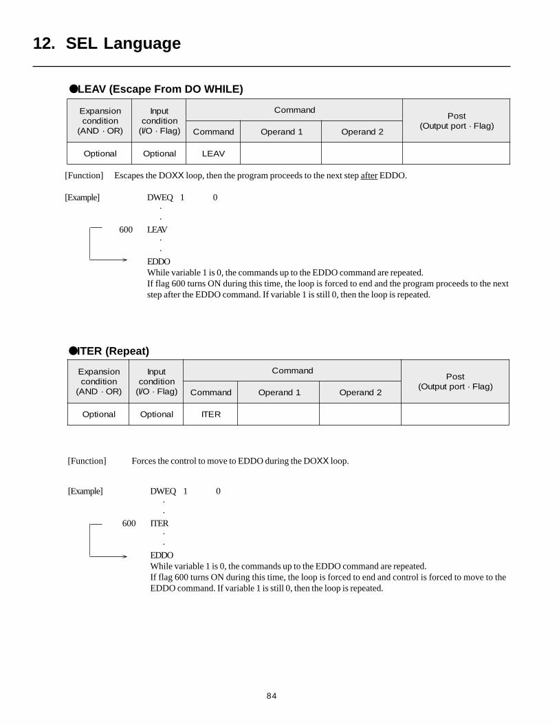
84
[Function] Escapes the DOXX loop, then the program proceeds to the next step after EDDO.
[Example] DWEQ 1 0 · ·
600 LEAV · ·EDDOWhile variable 1 is 0, the commands up to the EDDO command are repeated.If flag 600 turns ON during this time, the loop is forced to end and the program proceeds to the nextstep after the EDDO command. If variable 1 is still 0, then the loop is repeated.
noisnapxEnoitidnoc
)RO·DNA(
tupnInoitidnoc)galF·O/I(
dnammoCtsoP
)galF·troptuptuO(dnammoC 1dnarepO 2dnarepO
lanoitpO lanoitpO VAEL
noisnapxEnoitidnoc
)RO·DNA(
tupnInoitidnoc)galF·O/I(
dnammoCtsoP
)galF·troptuptuO(dnammoC 1dnarepO 2dnarepO
lanoitpO lanoitpO RETI
[Example] DWEQ 1 0 · ·
600 ITER · ·EDDOWhile variable 1 is 0, the commands up to the EDDO command are repeated.If flag 600 turns ON during this time, the loop is forced to end and control is forced to move to theEDDO command. If variable 1 is still 0, then the loop is repeated.
12. SEL Language
LEAV (Escape From DO WHILE)
ITER (Repeat)
[Function] Forces the control to move to EDDO during the DOXX loop.
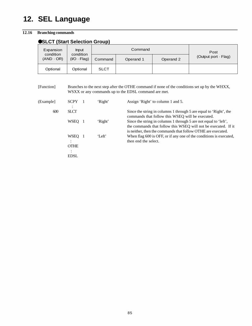
85
12.16 Branching commands
12. SEL Language
noisnapxEnoitidnoc
)RO·DNA(
tupnInoitidnoc)galF·O/I(
dnammoCtsoP
)galF·troptuptuO(dnammoC 1dnarepO 2dnarepO
lanoitpO lanoitpO TCLS
SLCT (Start Selection Group)
[Function] Branches to the next step after the OTHE command if none of the conditions set up by the WHXX,WSXX or any commands up to the EDSL command are met.
(Example] SCPY 1 ‘Right’ Assign ‘Right’ to column 1 and 5. :
600 SLCT Since the string in columns 1 through 5 are equal to ‘Right’, thecommands that follow this WSEQ will be executed.
WSEQ 1 ‘Right’ Since the string in columns 1 through 5 are not equal to ‘left’,the commands that follow this WSEQ will not be executed. If itis neither, then the commands that follow OTHE are executed.
WSEQ 1 ‘Left’ When flag 600 is OFF, or if any one of the conditions is executed, : then end the select.OTHE :EDSL
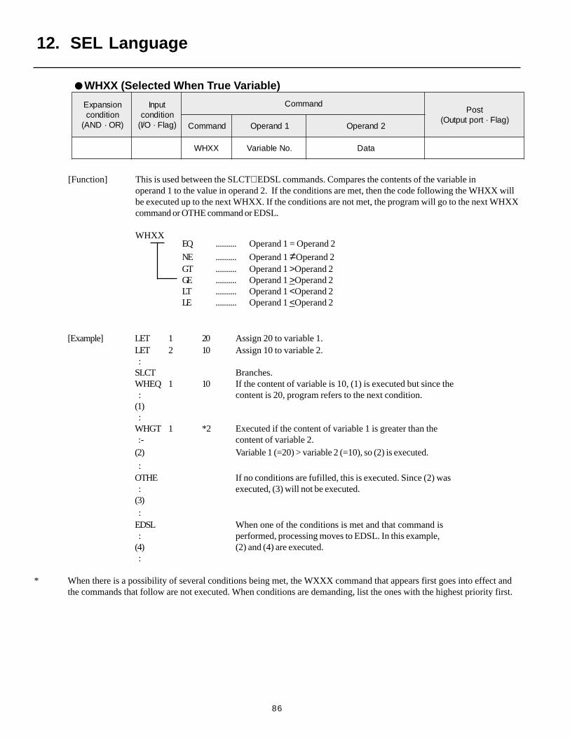
86
WHXX (Selected When True Variable)
12. SEL Language
noisnapxEnoitidnoc
)RO·DNA(
tupnInoitidnoc)galF·O/I(
dnammoCtsoP
)galF·troptuptuO(dnammoC 1dnarepO 2dnarepO
XXHW .oNelbairaV ataD
[Function] This is used between the SLCT∼ EDSL commands. Compares the contents of the variable inoperand 1 to the value in operand 2. If the conditions are met, then the code following the WHXX willbe executed up to the next WHXX. If the conditions are not met, the program will go to the next WHXXcommand or OTHE command or EDSL.
WHXXEQ .......... Operand 1 = Operand 2
NE .......... Operand 1 ≠Operand 2GT .......... Operand 1 >Operand 2GE .......... Operand 1 >Operand 2LT .......... Operand 1 <Operand 2LE .......... Operand 1 <Operand 2
[Example] LET 1 20 Assign 20 to variable 1.LET 2 10 Assign 10 to variable 2. :SLCT Branches.WHEQ 1 10 If the content of variable is 10, (1) is executed but since the : content is 20, program refers to the next condition.(1) :WHGT 1 *2 Executed if the content of variable 1 is greater than the :- content of variable 2.(2) Variable 1 (=20) > variable 2 (=10), so (2) is executed.
:OTHE If no conditions are fufilled, this is executed. Since (2) was : executed, (3) will not be executed.(3) :EDSL When one of the conditions is met and that command is : performed, processing moves to EDSL. In this example,(4) (2) and (4) are executed. :
* When there is a possibility of several conditions being met, the WXXX command that appears first goes into effect andthe commands that follow are not executed. When conditions are demanding, list the ones with the highest priority first.
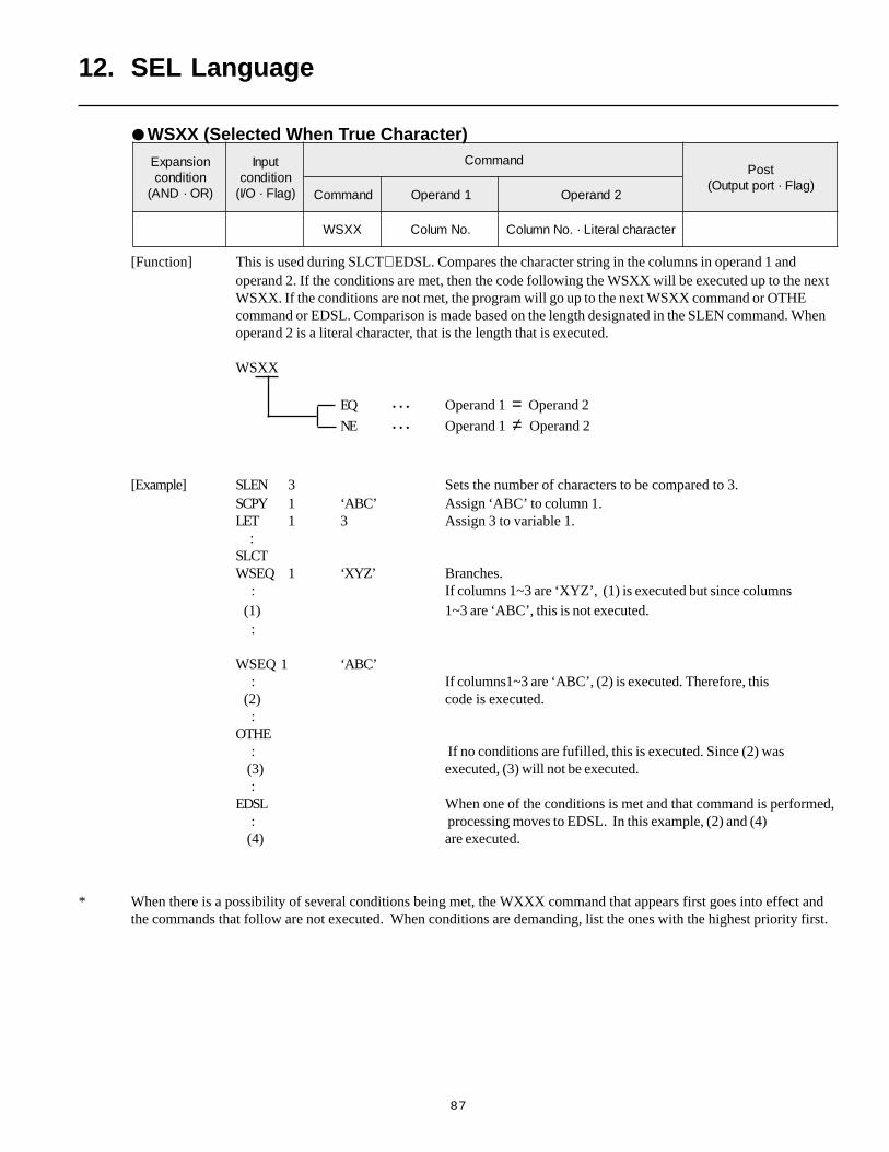
87
12. SEL Language
noisnapxEnoitidnoc
)RO·DNA(
tupnInoitidnoc)galF·O/I(
dnammoCtsoP
)galF·troptuptuO(dnammoC 1dnarepO 2dnarepO
XXSW .oNmuloC retcarahclaretiL·.oNnmuloC
[Function] This is used during SLCT∼ EDSL. Compares the character string in the columns in operand 1 andoperand 2. If the conditions are met, then the code following the WSXX will be executed up to the nextWSXX. If the conditions are not met, the program will go up to the next WSXX command or OTHEcommand or EDSL. Comparison is made based on the length designated in the SLEN command. Whenoperand 2 is a literal character, that is the length that is executed.
WSXX
EQ • • • Operand 1 = Operand 2
NE • • • Operand 1 ≠ Operand 2
[Example] SLEN 3 Sets the number of characters to be compared to 3.SCPY 1 ‘ABC’ Assign ‘ABC’ to column 1.LET 1 3 Assign 3 to variable 1. :SLCTWSEQ 1 ‘XYZ’ Branches. : If columns 1~3 are ‘XYZ’, (1) is executed but since columns (1) 1~3 are ‘ABC’, this is not executed. :
WSEQ 1 ‘ABC’ : If columns1~3 are ‘ABC’, (2) is executed. Therefore, this (2) code is executed. :OTHE : If no conditions are fufilled, this is executed. Since (2) was (3) executed, (3) will not be executed. :EDSL When one of the conditions is met and that command is performed, : processing moves to EDSL. In this example, (2) and (4) (4) are executed.
* When there is a possibility of several conditions being met, the WXXX command that appears first goes into effect andthe commands that follow are not executed. When conditions are demanding, list the ones with the highest priority first.
WSXX (Selected When True Character)
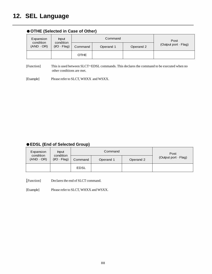
88
12. SEL Language
EDSL (End of Selected Group)
noisnapxEnoitidnoc
)RO·DNA(
tupnInoitidnoc)galF·O/I(
dnammoCtsoP
)galF·troptuptuO(dnammoC 1dnarepO 2dnarepO
EHTO
[Function] This is used between SLCT~EDSL commands. This declares the command to be executed when no other conditions are met.
[Example] Please refer to SLCT, WHXX and WSXX.
noisnapxEnoitidnoc
)RO·DNA(
tupnInoitidnoc)galF·O/I(
dnammoCtsoP
)galF·troptuptuO(dnammoC 1dnarepO 2dnarepO
LSDE
OTHE (Selected in Case of Other)
[Function] Declares the end of SLCT command.
[Example] Please refer to SLCT, WHXX and WSXX.

89
12.17 External input output command
[Function] Opens the channel specified in operand 1. Channels specified after this will be able to transmit and receivesignals. An ending character must be set by the SCHA command before executing this command.
[Example] SCHA 10 Designate 10 (=LF) as the ending character.OPEN 1 Open channel 1.
SCHA 13 Designate 13 (=CR) as the ending character.LET 1 2 Assign 2 to variable 1. Open channel 2, the value contained in variable 1.OPEN *1
[Function] Closes the channel specified in operand 1. Channels specified after this will be unable to transmit and receive signals.
[Example] CLOS 1 Close the channel.
[Example] LET 1 2 Assign 2 to variable 1.CLOS *1 Close channel 2, the value contained in variable 1.
noisnapxEnoitidnoc
)RO·DNA(
tupnInoitidnoc)galF·O/I(
dnammoCtsoP
)galF·troptuptuO(dnammoC 1dnarepO 2dnarepO
lanoitpO lanoitpO NEPO .oNlennahC
noisnapxEnoitidnoc
)RO·DNA(
tupnInoitidnoc)galF·O/I(
dnammoCtsoP
)galF·troptuptuO(dnammoC 1dnarepO 2dnarepO
lanoitpO lanoitpO SOLC .oNlennahC
12. SEL Language
OPEN (Open Channel)
CLOS (Close Channel)
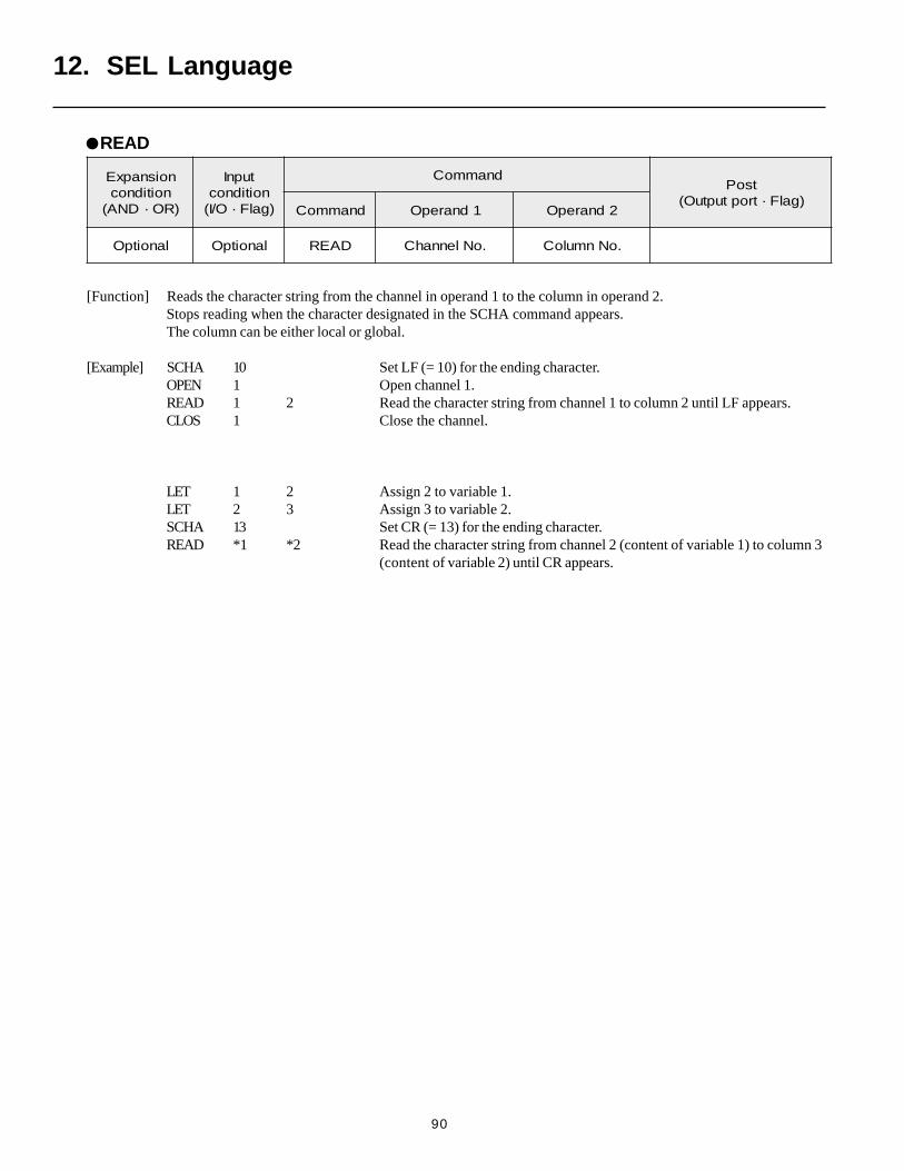
90
[Function] Reads the character string from the channel in operand 1 to the column in operand 2.Stops reading when the character designated in the SCHA command appears.The column can be either local or global.
[Example] SCHA 10 Set LF (= 10) for the ending character.OPEN 1 Open channel 1.READ 1 2 Read the character string from channel 1 to column 2 until LF appears.CLOS 1 Close the channel.
LET 1 2 Assign 2 to variable 1.LET 2 3 Assign 3 to variable 2.SCHA 13 Set CR (= 13) for the ending character.READ *1 *2 Read the character string from channel 2 (content of variable 1) to column 3
(content of variable 2) until CR appears.
noisnapxEnoitidnoc
)RO·DNA(
tupnInoitidnoc)galF·O/I(
dnammoCtsoP
)galF·troptuptuO(dnammoC 1dnarepO 2dnarepO
lanoitpO lanoitpO DAER .oNlennahC .oNnmuloC
READ
12. SEL Language

91
12. SEL Language
[Function] Writes the character string from the channel in operand 1 to the column in operand 2.Stops writing after the character designated in the SCHA command is written.The column can be either local or global.
[Example] SCHA 10 Set LF (= 10) for the ending character.OPEN 1 Open channel 1.WRIT 1 2 Write the character string from channel 1 to column 2 until LF appears.CLOS 1 Close the channel.
LET 1 2 Assign 2 to variable 1.LET 2 3 Assign 3 to variable 2.SCHA 13 Set CR (= 13) for the ending character.WRIT *1 *2 Read the character string from channel 2 (content of variable 1) to column 3
(content of variable 2) until CR appears.
noisnapxEnoitidnoc
)RO·DNA(
tupnInoitidnoc)galF·O/I(
dnammoCtsoP
)galF·troptuptuO(dnammoC 1dnarepO 2dnarepO
lanoitpO lanoitpO TIRW .oNlennahC .oNnmuloC
WRIT (Write)
noisnapxEnoitidnoc
)RO·DNA(
tupnInoitidnoc)galF·O/I(
dnammoCtsoP
)galF·troptuptuO(dnammoC 1dnarepO 2dnarepO
lanoitpO lanoitpO AHCS edocretcarahC .oNnmuloC
SCHA (Set Ending Letter)
[Function] Sets the ending letter to be used in the READ command and WRIT command. A value from 0 ~ 255
(character code used in BASIC) can be designated for the character.
[Example] Refer to the READ command and WRIT command.
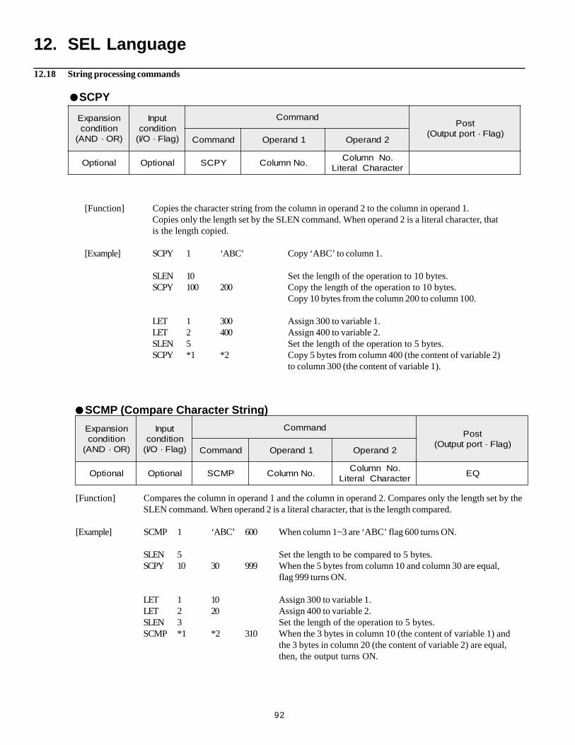
92
[Function] Copies the character string from the column in operand 2 to the column in operand 1.Copies only the length set by the SLEN command. When operand 2 is a literal character, thatis the length copied.
[Example] SCPY 1 ‘ABC’ Copy ‘ABC’ to column 1.
SLEN 10 Set the length of the operation to 10 bytes.SCPY 100 200 Copy the length of the operation to 10 bytes.
Copy 10 bytes from the column 200 to column 100.
LET 1 300 Assign 300 to variable 1.LET 2 400 Assign 400 to variable 2.SLEN 5 Set the length of the operation to 5 bytes.SCPY *1 *2 Copy 5 bytes from column 400 (the content of variable 2)
to column 300 (the content of variable 1).
noisnapxEnoitidnoc
)RO·DNA(
tupnInoitidnoc)galF·O/I(
dnammoCtsoP
)galF·troptuptuO(dnammoC 1dnarepO 2dnarepO
lanoitpO lanoitpO YPCS .oNnmuloC.oNnmuloC
retcarahClaretiL
12. SEL Language
SCPY
SCMP (Compare Character String)
noisnapxEnoitidnoc
)RO·DNA(
tupnInoitidnoc)galF·O/I(
dnammoCtsoP
)galF·troptuptuO(dnammoC 1dnarepO 2dnarepO
lanoitpO lanoitpO PMCS .oNnmuloC.oNnmuloC
retcarahClaretiLQE
[Function] Compares the column in operand 1 and the column in operand 2. Compares only the length set by theSLEN command. When operand 2 is a literal character, that is the length compared.
[Example] SCMP 1 ‘ABC’ 600 When column 1~3 are ‘ABC’ flag 600 turns ON.
SLEN 5 Set the length to be compared to 5 bytes.SCPY 10 30 999 When the 5 bytes from column 10 and column 30 are equal,
flag 999 turns ON.
LET 1 10 Assign 300 to variable 1.LET 2 20 Assign 400 to variable 2.SLEN 3 Set the length of the operation to 5 bytes.SCMP *1 *2 310 When the 3 bytes in column 10 (the content of variable 1) and
the 3 bytes in column 20 (the content of variable 2) are equal,then, the output turns ON.
12.18 String processing commands
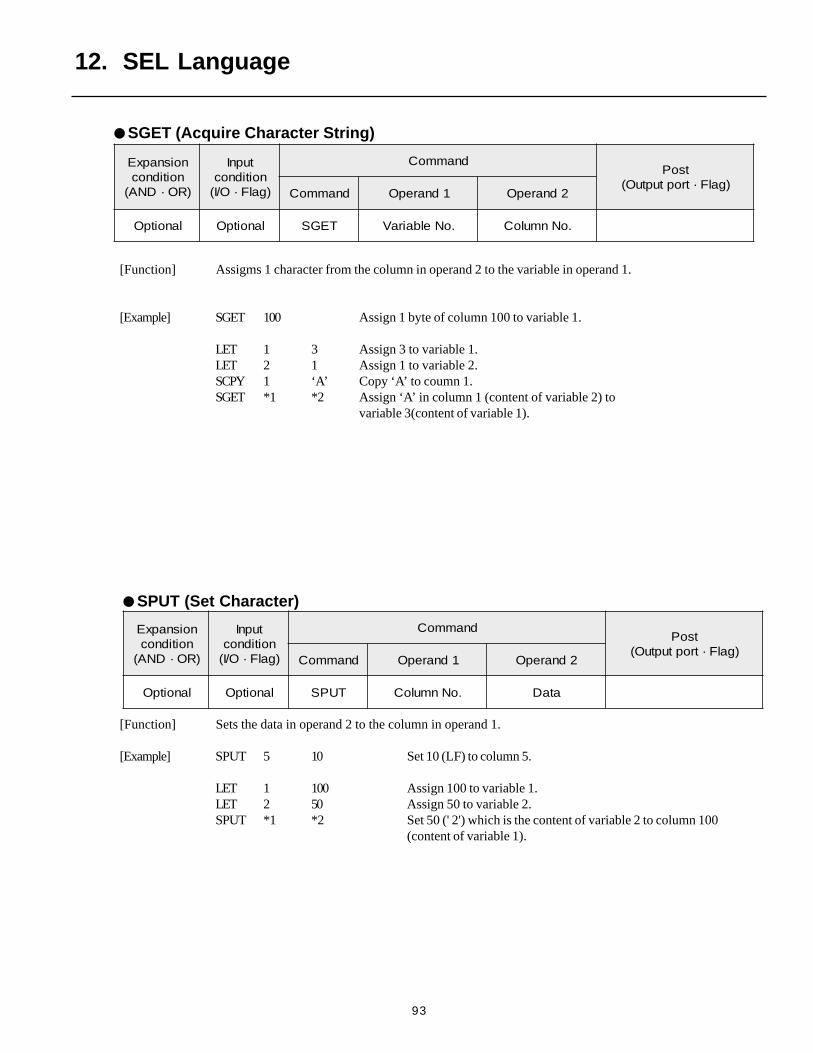
93
[Function] Sets the data in operand 2 to the column in operand 1.
[Example] SPUT 5 10 Set 10 (LF) to column 5.
LET 1 100 Assign 100 to variable 1.LET 2 50 Assign 50 to variable 2.SPUT *1 *2 Set 50 (' 2') which is the content of variable 2 to column 100
(content of variable 1).
noisnapxEnoitidnoc
)RO·DNA(
tupnInoitidnoc)galF·O/I(
dnammoCtsoP
)galF·troptuptuO(dnammoC 1dnarepO 2dnarepO
lanoitpO lanoitpO TUPS .oNnmuloC ataD
12. SEL Language
SPUT (Set Character)
noisnapxEnoitidnoc
)RO·DNA(
tupnInoitidnoc)galF·O/I(
dnammoCtsoP
)galF·troptuptuO(dnammoC 1dnarepO 2dnarepO
lanoitpO lanoitpO TEGS .oNelbairaV .oNnmuloC
[Function] Assigms 1 character from the column in operand 2 to the variable in operand 1.
[Example] SGET 100 Assign 1 byte of column 100 to variable 1.
LET 1 3 Assign 3 to variable 1.LET 2 1 Assign 1 to variable 2.SCPY 1 ‘A’ Copy ‘A’ to coumn 1.SGET *1 *2 Assign ‘A’ in column 1 (content of variable 2) to
variable 3(content of variable 1).
SGET (Acquire Character String)
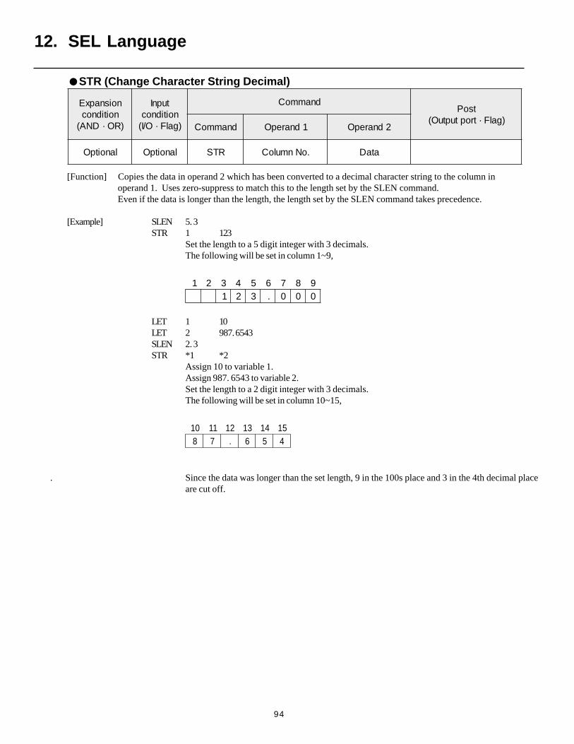
94
[Function] Copies the data in operand 2 which has been converted to a decimal character string to the column inoperand 1. Uses zero-suppress to match this to the length set by the SLEN command.Even if the data is longer than the length, the length set by the SLEN command takes precedence.
[Example] SLEN 5. 3STR 1 123
Set the length to a 5 digit integer with 3 decimals.The following will be set in column 1~9,
1 2 3 4 5 6 7 8 91 2 3 . 0 0 0
LET 1 10LET 2 987. 6543SLEN 2. 3STR *1 *2
Assign 10 to variable 1.Assign 987. 6543 to variable 2.Set the length to a 2 digit integer with 3 decimals.The following will be set in column 10~15,
01 11 21 31 41 518 7 . 6 5 4
. Since the data was longer than the set length, 9 in the 100s place and 3 in the 4th decimal placeare cut off.
12. SEL Language
STR (Change Character String Decimal)
noisnapxEnoitidnoc
)RO·DNA(
tupnInoitidnoc)galF·O/I(
dnammoCtsoP
)galF·troptuptuO(dnammoC 1dnarepO 2dnarepO
lanoitpO lanoitpO RTS .oNnmuloC ataD
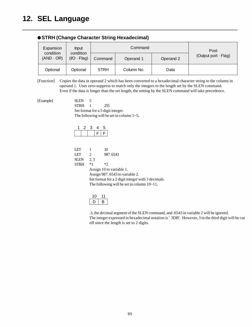
95
[Function] Copies the data in operand 2 which has been converted to a hexadecimal character string to the column inoperand 1. Uses zero-suppress to match only the integers to the length set by the SLEN command.Even if the data is longer than the set length, the setting by the SLEN command will take precedence.
[Example] SLEN 5STRH 1 255Set format for a 5 digit integer.The following will be set in column 1~5,
1 2 3 4 5F F
LET 1 10LET 2 987. 6543SLEN 2. 3STRH *1 *2
Assign 10 to variable 1.Assign 987. 6543 to variable 2.Set format for a 2 digit integer with 3 decimals.The following will be set in column 10~11,
01 11D B
.3, the decimal segment of the SLEN command, and .6543 in variable 2 will be ignored.The integer expressed in hexadecimal notation is ' 3DB'. However, 3 in the third digit will be cutoff since the length is set to 2 digits.
12. SEL Language
STRH (Change Character String Hexadecimal)
noisnapxEnoitidnoc
)RO·DNA(
tupnInoitidnoc)galF·O/I(
dnammoCtsoP
)galF·troptuptuO(dnammoC 1dnarepO 2dnarepO
lanoitpO lanoitpO HRTS .oNnmuloC ataD
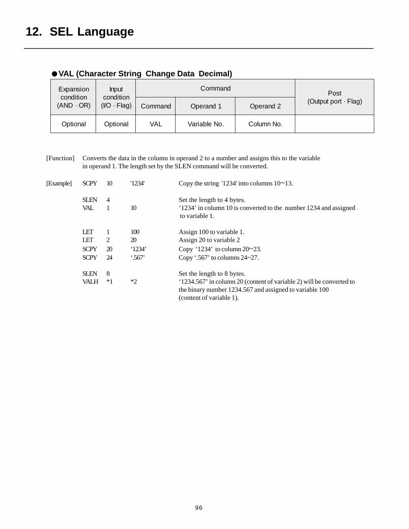
96
12. SEL Language
[Function] Converts the data in the column in operand 2 to a number and assigns this to the variablein operand 1. The length set by the SLEN command will be converted.
[Example] SCPY 10 '1234' Copy the string '1234' into columns 10~13.
SLEN 4 Set the length to 4 bytes.VAL 1 10 ‘1234’ in column 10 is converted to the number 1234 and assigned
to variable 1.
LET 1 100 Assign 100 to variable 1.LET 2 20 Assign 20 to variable 2SCPY 20 ‘1234’ Copy ‘1234’ to column 20~23.SCPY 24 ‘.567’ Copy ‘.567’ to columns 24~27.
SLEN 8 Set the length to 8 bytes.VALH *1 *2 ‘1234.567’ in column 20 (content of variable 2) will be converted to
the binary number 1234.567 and assigned to variable 100(content of variable 1).
noisnapxEnoitidnoc
)RO·DNA(
tupnInoitidnoc)galF·O/I(
dnammoCtsoP
)galF·troptuptuO(dnammoC 1dnarepO 2dnarepO
lanoitpO lanoitpO LAV .oNelbairaV .oNnmuloC
VAL (Character String Change Data Decimal)

97
12. SEL Language
[Function] Converts the hexadecimal data in the column in operand 2 to a decimal number and assigns this to the variable in operand 1. The length set by the SLEN command will be converted. Only the integers will be convertedand the decimal places will be disregarded.
[Example] SCPY 10 ' 1234' Set ' 1234' in column 10.SLEN 4 Set the length to 4 bytes.VAL 1 10 The hexadecimal number ' 1234' in column 10 is converted to the
number 4660 and assigned to variable 1.
LET 1 100 Assign 100 to variable 1.LET 2 20 Assign 20 to variable 2SCPY 20 ' ABCD' Copy ' ABCD' to column 20.SLEN 4 Set the length to 4 bytes.VALH *1 *2 The hexadecimal ' ABCD' in column 20 (content of variable 2) will be
converted to the binary number 43982 and assigned to variable 100(content of variable 1).
noisnapxEnoitidnoc
)RO·DNA(
tupnInoitidnoc)galF·O/I(
dnammoCtsoP
)galF·troptuptuO(dnammoC 1dnarepO 2dnarepO
lanoitpO lanoitpO HLAV .oNelbairaV .oNnmuloC
VALH (Character String Data Hexadecimal)
noisnapxEnoitidnoc
)RO·DNA(
tupnInoitidnoc)galF·O/I(
dnammoCtsoP
)galF·troptuptuO(dnammoC 1dnarepO 2dnarepO
lanoitpO lanoitpO NELS htgneL
SLEN (Set Length)
[Function] Sets the length for the string command.
SCMP ··· Decimals Invalid
SCPY ··· Decimals Invalid
ISXX ··· Decimals Invalid
STRH ··· Decimals Invalid
VAL,VALH ··· Decimals Invalid
STR ··· Decimals Valid
[Example] Refer to each of the commands above.
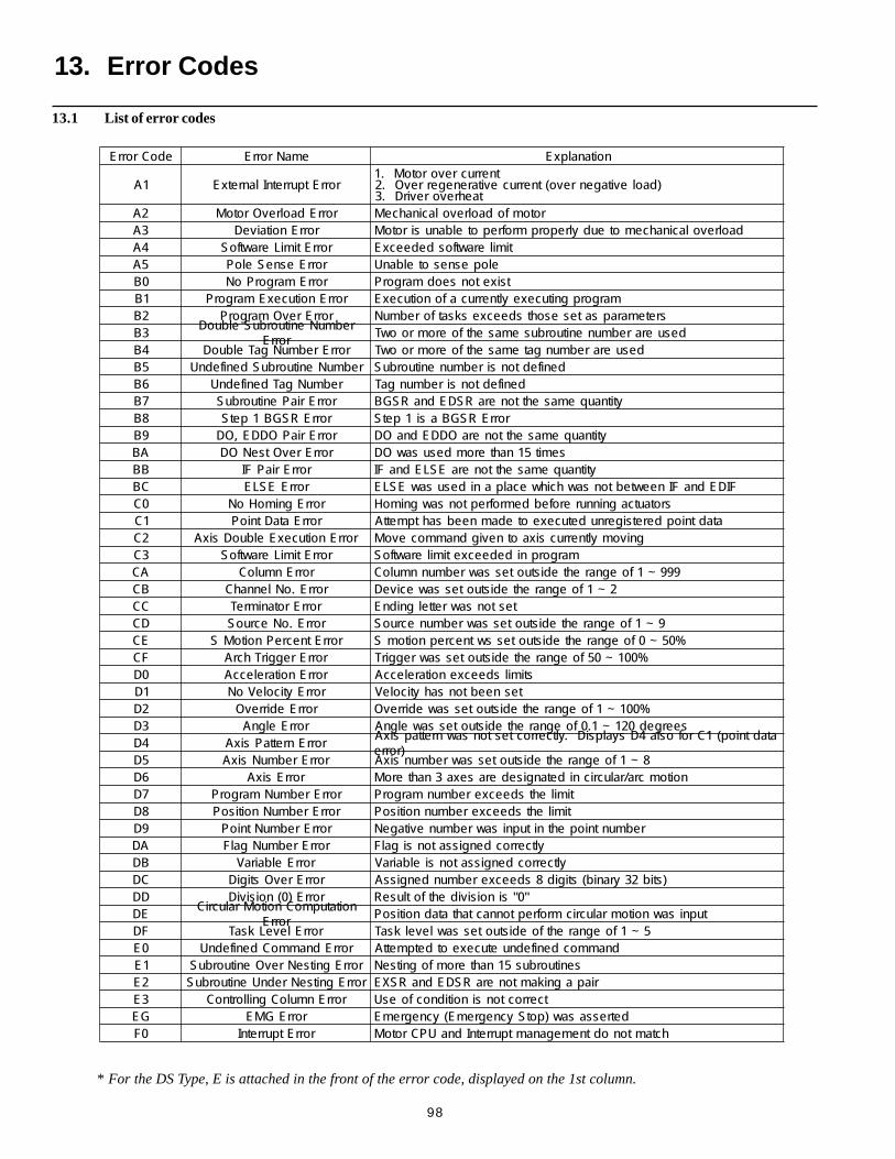
98
edoCrorrE emaNrorrE noitanalpxE
1A rorrEtpurretnIlanretxEtnerrucrevorotoM.1
)daolevitagenrevo(tnerrucevitarenegerrevO.2taehrevorevirD.3
2A rorrEdaolrevOrotoM rotomfodaolrevolacinahceM3A rorrEnoitaiveD daolrevolacinahcemoteudylreporpmrofrepotelbanusirotoM4A rorrEtimiLerawtfoS timilerawtfosdedeecxE5A rorrEesneSeloP elopesnesotelbanU0B rorrEmargorPoN tsixetonseodmargorP1B rorrEnoitucexEmargorP margorpgnitucexeyltnerrucafonoitucexE2B rorrErevOmargorP sretemarapsatesesohtsdeecxesksatforebmuN3B
rebmuNenituorbuSelbuoDrorrE
desuerarebmunenituorbusemasehtfoeromroowT4B rorrErebmuNgaTelbuoD desuerarebmungatemasehtfoeromroowT5B rebmuNenituorbuSdenifednU denifedtonsirebmunenituorbuS6B rebmuNgaTdenifednU denifedtonsirebmungaT7B rorrEriaPenituorbuS ytitnauqemasehttoneraRSDEdnaRSGB8B rorrERSGB1petS rorrERSGBasi1petS9B rorrEriaPODDE,OD ytitnauqemasehttoneraODDEdnaODAB rorrErevOtseNOD semit51nahteromdesusawODBB rorrEriaPFI ytitnauqemasehttoneraESLEdnaFICB rorrEESLE FIDEdnaFIneewtebtonsawhcihwecalpanidesusawESLE0C rorrEgnimoHoN srotautcagninnurerofebdemrofreptonsawgnimoH1C rorrEataDtnioP atadtniopderetsigernudetucexeotedamneebsahtpmettA2C rorrEnoitucexEelbuoDsixA gnivomyltnerrucsixaotnevigdnammocevoM3C rorrEtimiLerawtfoS margorpnidedeecxetimilerawtfoSAC rorrEnmuloC 999~1foegnarehtedistuotessawrebmunnmuloCBC rorrE.oNlennahC 2~1foegnarehtedistuotessaweciveDCC rorrErotanimreT testonsawrettelgnidnEDC rorrE.oNecruoS 9~1foegnarehtedistuotessawrebmunecruoSEC rorrEtnecrePnoitoMS %05~0foegnarehtedistuotesswtnecrepnoitomSFC rorrEreggirThcrA %001~05foegnarehtedistuotessawreggirT0D rorrEnoitareleccA stimilsdeecxenoitareleccA1D rorrEyticoleVoN tesneebtonsahyticoleV2D rorrEedirrevO %001~1foegnarehtedistuotessawedirrevO3D rorrEelgnA seerged021~1.0foegnarehtedistuotessawelgnA4D rorrEnrettaPsixA
atadtniop(1Crofosla4DsyalpsiD.yltcerroctestonsawnrettapsixA)rorre
5D rorrErebmuNsixA 8~1foegnarehtedistuotessawrebmunsixA6D rorrEsixA noitomcra/ralucricnidetangisederasexa3nahteroM7D rorrErebmuNmargorP timilehtsdeecxerebmunmargorP8D rorrErebmuNnoitisoP timilehtsdeecxerebmunnoitisoP9D rorrErebmuNtnioP rebmuntniopehtnitupnisawrebmunevitageNAD rorrErebmuNgalF yltcerrocdengissatonsigalFBD rorrEelbairaV yltcerrocdengissatonsielbairaVCD rorrErevOstigiD )stib23yranib(stigid8sdeecxerebmundengissADD rorrE)0(noisiviD "0"sinoisividehtfotluseRED
noitatupmoCnoitoMralucriCrorrE
tupnisawnoitomralucricmrofreptonnactahtatadnoitisoPFD rorrEleveLksaT 5~1foegnarehtfoedistuotessawlevelksaT0E rorrEdnammoCdenifednU dnammocdenifednuetucexeotdetpmettA1E rorrEgnitseNrevOenituorbuS senituorbus51nahteromfognitseN2E rorrEgnitseNrednUenituorbuS riapagnikamtoneraRSDEdnaRSXE3E rorrEnmuloCgnillortnoC tcerroctonsinoitidnocfoesUGE rorrEGME detressasaw)potSycnegremE(ycnegremE0F rorrEtpurretnI hctamtonodtnemeganamtpurretnIdnaUPCrotoM
13.1 List of error codes
* For the DS Type, E is attached in the front of the error code, displayed on the 1st column.
13. Error Codes
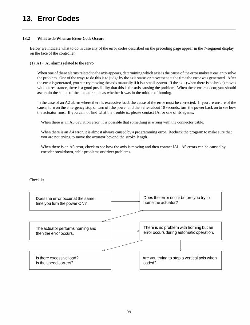
99
13.2 What to do When an Error Code Occurs
Below we indicate what to do in case any of the error codes described on the preceding page appear in the 7-segment displayon the face of the controller.
(1) A1 ~ A5 alarms related to the servo
When one of these alarms related to the axis appears, determining which axis is the cause of the error makes it easier to solvethe problem. One of the ways to do this is to judge by the axis status or movement at the time the error was generated. Afterthe error is generated, you can try moving the axis manually if it is a small system. If the axis (when there is no brake) moveswithout resistance, there is a good possibility that this is the axis causing the problem. When these errors occur, you shouldascertain the status of the actuator such as whether it was in the middle of homing.
In the case of an A2 alarm where there is excessive load, the cause of the error must be corrected. If you are unsure of thecause, turn on the emergency stop or turn off the power and then after about 10 seconds, turn the power back on to see howthe actuator runs. If you cannot find what the trouble is, please contact IAI or one of its agents.
When there is an A3 deviation error, it is possible that something is wrong with the connector cable.
When there is an A4 error, it is almost always caused by a programming error. Recheck the program to make sure thatyou are not trying to move the actuator beyond the stroke length.
When there is an A5 error, check to see how the axis is moving and then contact IAI. A5 errors can be caused byencoder breakdown, cable problems or driver problems.
Does the error occur at the sametime you turn the power ON?
Checklist
Does the error occur before you try tohome the actuator?
The actuator performs homing andthen the error occurs.
There is no problem with homing but anerror occurs during automatic operation.
Is there excessive load?Is the speed correct?
Are you trying to stop a vertical axis whenloaded?
13. Error Codes
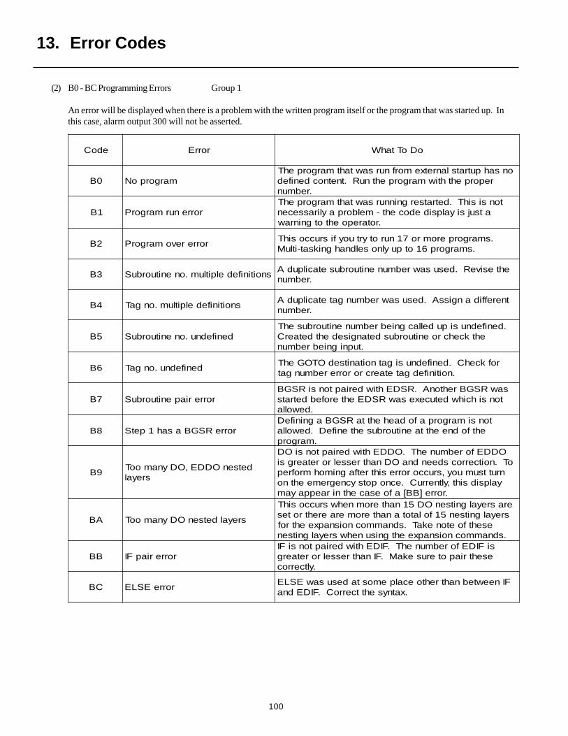
100
(2) B0 - BC Programming Errors Group 1
An error will be displayed when there is a problem with the written program itself or the program that was started up. Inthis case, alarm output 300 will not be asserted.
edoC rorrE oDoTtahW
0B margorpoNonsahputratslanretxemorfnursawtahtmargorpehT
reporpehthtiwmargorpehtnuR.tnetnocdenifed.rebmun
1B rorrenurmargorPtonsisihT.detratsergninnursawtahtmargorpehT
atsujsiyalpsidedoceht-melborpaylirassecen.rotarepoehtotgninraw
2B rorrerevomargorP.smargorperomro71nurotyrtuoyfisruccosihT
.smargorp61otpuylnoseldnahgniksat-itluM
3B snoitinifedelpitlum.onenituorbuSehtesiveR.desusawrebmunenituorbusetacilpudA
.rebmun
4B snoitinifedelpitlum.ongaTtnereffidangissA.desusawrebmungatetacilpudA
.rebmun
5B denifednu.onenituorbuS.denifednusipudellacgniebrebmunenituorbusehT
ehtkcehcroenituorbusdetangisedehtdetaerC.tupnigniebrebmun
6B denifednu.ongaTrofkcehC.denifednusigatnoitanitsedOTOGehT
.noitinifedgatetaercrororrerebmungat
7B rorreriapenituorbuSsawRSGBrehtonA.RSDEhtiwderiaptonsiRSGB
tonsihcihwdetucexesawRSDEehterofebdetrats.dewolla
8B rorreRSGBasah1petStonsimargorpafodaehehttaRSGBagninifeD
ehtfodneehttaenituorbusehtenifeD.dewolla.margorp
9BdetsenODDE,ODynamooT
sreyal
ODDEforebmunehT.ODDEhtiwderiaptonsiODoT.noitcerrocsdeendnaODnahtresselroretaergsi
nruttsumuoy,sruccororresihtretfagnimohmrofrepyalpsidsiht,yltnerruC.ecnopotsycnegremeehtno
.rorre]BB[afoesacehtniraeppayam
AB sreyaldetsenODynamooT
erasreyalgnitsenOD51nahteromnehwsruccosihTsreyalgnitsen51folatotanahteromeraerehtrotes
esehtfoetonekaT.sdnammocnoisnapxeehtrof.sdnammocnoisnapxeehtgnisunehwsreyalgnitsen
BB rorreriapFIsiFIDEforebmunehT.FIDEhtiwderiaptonsiFIesehtriapoterusekaM.FInahtresselroretaerg
.yltcerroc
CB rorreESLEFIneewtebnahtrehtoecalpemostadesusawESLE
.xatnysehttcerroC.FIDEdna
13. Error Codes
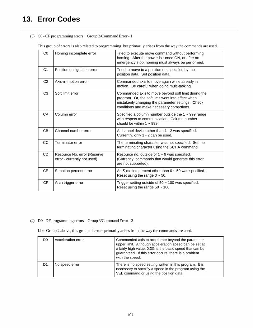
101
(3) C0 - CF programming errors Group 2/Command Error - 1
This group of errors is also related to programming, but primarily arises from the way the commands are used.
C0 Homing incomplete error Tried to execute move command without performinghoming. After the power is turned ON, or after anemergency stop, homing must always be performed.
C1 Position designation error Tried to move to a position not specified by theposition data. Set position data.
C2 Axis-in-motion error Commanded axis to move again while already inmotion. Be careful when doing multi-tasking.
C3 Soft limit error Commanded axis to move beyond soft limit during theprogram. Or, the soft limit went into effect whenmistakenly changing the parameter settings. Checkconditions and make necessary corrections.
CA Column error Specified a column number outside the 1 ~ 999 rangewith respect to communication. Column numbershould be within 1 ~ 999.
CB Channel number error A channel device other than 1 - 2 was specified.Currently, only 1 - 2 can be used.
CC Terminator error The terminating character was not specified. Set theterminating character using the SCHA command.
CD Resource No. error (Reserveerror - currently not used)
Resource no. outside of 1 ~ 9 was specified.(Currently, commands that would generate this errorare not supported).
CE S motion percent error An S motion percent other than 0 ~ 50 was specified.Reset using the range 0 ~ 50.
CF Arch trigger error Trigger setting outside of 50 ~ 100 was specified.Reset using the range 50 ~ 100.
(4) D0 - DF programming errors Group 3/Command Error - 2
Like Group 2 above, this group of errors primarily arises from the way the commands are used.
D0 Acceleration error Commanded axis to accelerate beyond the parameterupper limit. Although acceleration speed can be set ata fairly high value, 0.3G is the basic speed that can beguaranteed. If this error occurs, there is a problemwith the speed.
D1 No speed error There is no speed setting written in this program. It isnecessary to specifiy a speed in the program using theVEL command or using the position data.
13. Error Codes
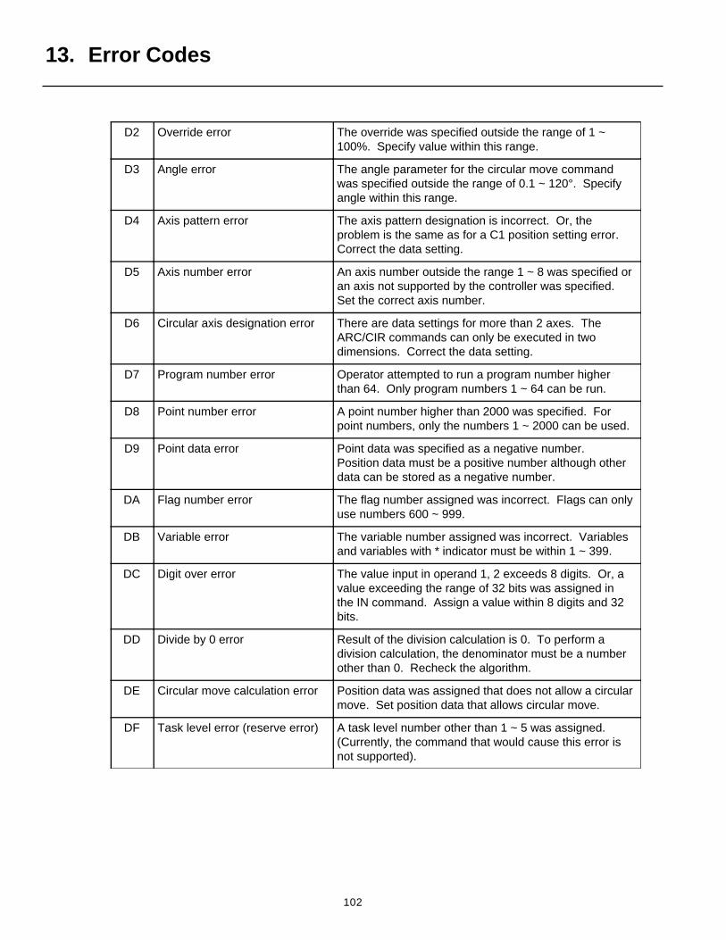
102
D2 Override error The override was specified outside the range of 1 ~100%. Specify value within this range.
D3 Angle error The angle parameter for the circular move commandwas specified outside the range of 0.1 ~ 120°. Specifyangle within this range.
D4 Axis pattern error The axis pattern designation is incorrect. Or, theproblem is the same as for a C1 position setting error.Correct the data setting.
D5 Axis number error An axis number outside the range 1 ~ 8 was specified oran axis not supported by the controller was specified.Set the correct axis number.
D6 Circular axis designation error There are data settings for more than 2 axes. TheARC/CIR commands can only be executed in twodimensions. Correct the data setting.
D7 Program number error Operator attempted to run a program number higherthan 64. Only program numbers 1 ~ 64 can be run.
D8 Point number error A point number higher than 2000 was specified. Forpoint numbers, only the numbers 1 ~ 2000 can be used.
D9 Point data error Point data was specified as a negative number.Position data must be a positive number although otherdata can be stored as a negative number.
DA Flag number error The flag number assigned was incorrect. Flags can onlyuse numbers 600 ~ 999.
DB Variable error The variable number assigned was incorrect. Variablesand variables with * indicator must be within 1 ~ 399.
DC Digit over error The value input in operand 1, 2 exceeds 8 digits. Or, avalue exceeding the range of 32 bits was assigned inthe IN command. Assign a value within 8 digits and 32bits.
DD Divide by 0 error Result of the division calculation is 0. To perform adivision calculation, the denominator must be a numberother than 0. Recheck the algorithm.
DE Circular move calculation error Position data was assigned that does not allow a circularmove. Set position data that allows circular move.
DF Task level error (reserve error) A task level number other than 1 ~ 5 was assigned.(Currently, the command that would cause this error isnot supported).
13. Error Codes
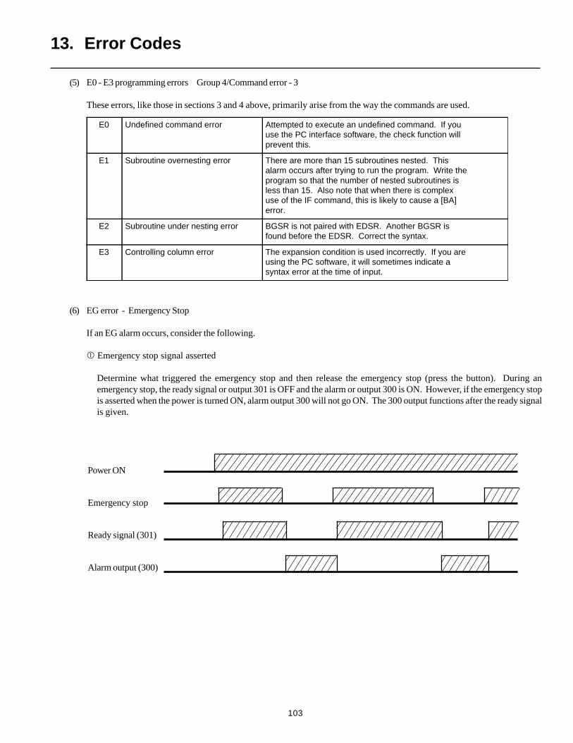
103
(5) E0 - E3 programming errors Group 4/Command error - 3
These errors, like those in sections 3 and 4 above, primarily arise from the way the commands are used.
(6) EG error - Emergency Stop
If an EG alarm occurs, consider the following.
Emergency stop signal asserted
Determine what triggered the emergency stop and then release the emergency stop (press the button). During anemergency stop, the ready signal or output 301 is OFF and the alarm or output 300 is ON. However, if the emergency stopis asserted when the power is turned ON, alarm output 300 will not go ON. The 300 output functions after the ready signalis given.
E0 Undefined command error Attempted to execute an undefined command. If youuse the PC interface software, the check function willprevent this.
E1 Subroutine overnesting error There are more than 15 subroutines nested. Thisalarm occurs after trying to run the program. Write theprogram so that the number of nested subroutines isless than 15. Also note that when there is complexuse of the IF command, this is likely to cause a [BA]error.
E2 Subroutine under nesting error BGSR is not paired with EDSR. Another BGSR isfound before the EDSR. Correct the syntax.
E3 Controlling column error The expansion condition is used incorrectly. If you areusing the PC software, it will sometimes indicate asyntax error at the time of input.
Power ON
Emergency stop
Ready signal (301)
Alarm output (300)
13. Error Codes
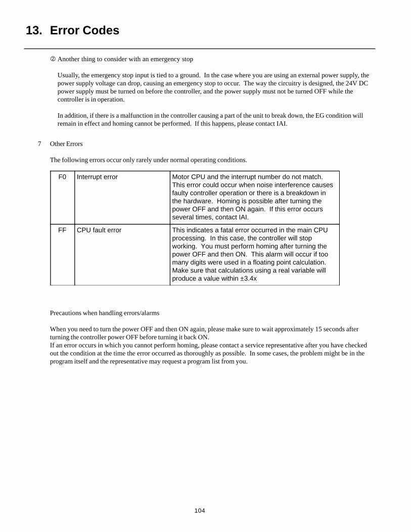
104
Another thing to consider with an emergency stop
Usually, the emergency stop input is tied to a ground. In the case where you are using an external power supply, thepower supply voltage can drop, causing an emergency stop to occur. The way the circuitry is designed, the 24V DCpower supply must be turned on before the controller, and the power supply must not be turned OFF while thecontroller is in operation.
In addition, if there is a malfunction in the controller causing a part of the unit to break down, the EG condition willremain in effect and homing cannot be performed. If this happens, please contact IAI.
7 Other Errors
The following errors occur only rarely under normal operating conditions.
Precautions when handling errors/alarms
When you need to turn the power OFF and then ON again, please make sure to wait approximately 15 seconds afterturning the controller power OFF before turning it back ON.If an error occurs in which you cannot perform homing, please contact a service representative after you have checkedout the condition at the time the error occurred as thoroughly as possible. In some cases, the problem might be in theprogram itself and the representative may request a program list from you.
F0 Interrupt error Motor CPU and the interrupt number do not match.This error could occur when noise interference causesfaulty controller operation or there is a breakdown inthe hardware. Homing is possible after turning thepower OFF and then ON again. If this error occursseveral times, contact IAI.
FF CPU fault error This indicates a fatal error occurred in the main CPUprocessing. In this case, the controller will stopworking. You must perform homing after turning thepower OFF and then ON. This alarm will occur if toomany digits were used in a floating point calculation.Make sure that calculations using a real variable willproduce a value within ±3.4x
13. Error Codes

Intelligent Actuator Inc.2690 W. 237th StreetTorrance, CA 90505
310-891-6015 / 310-891-0815 (Fax)www.intelligentactuator.com
Publication No. IAI-040CPublication Date April 1998
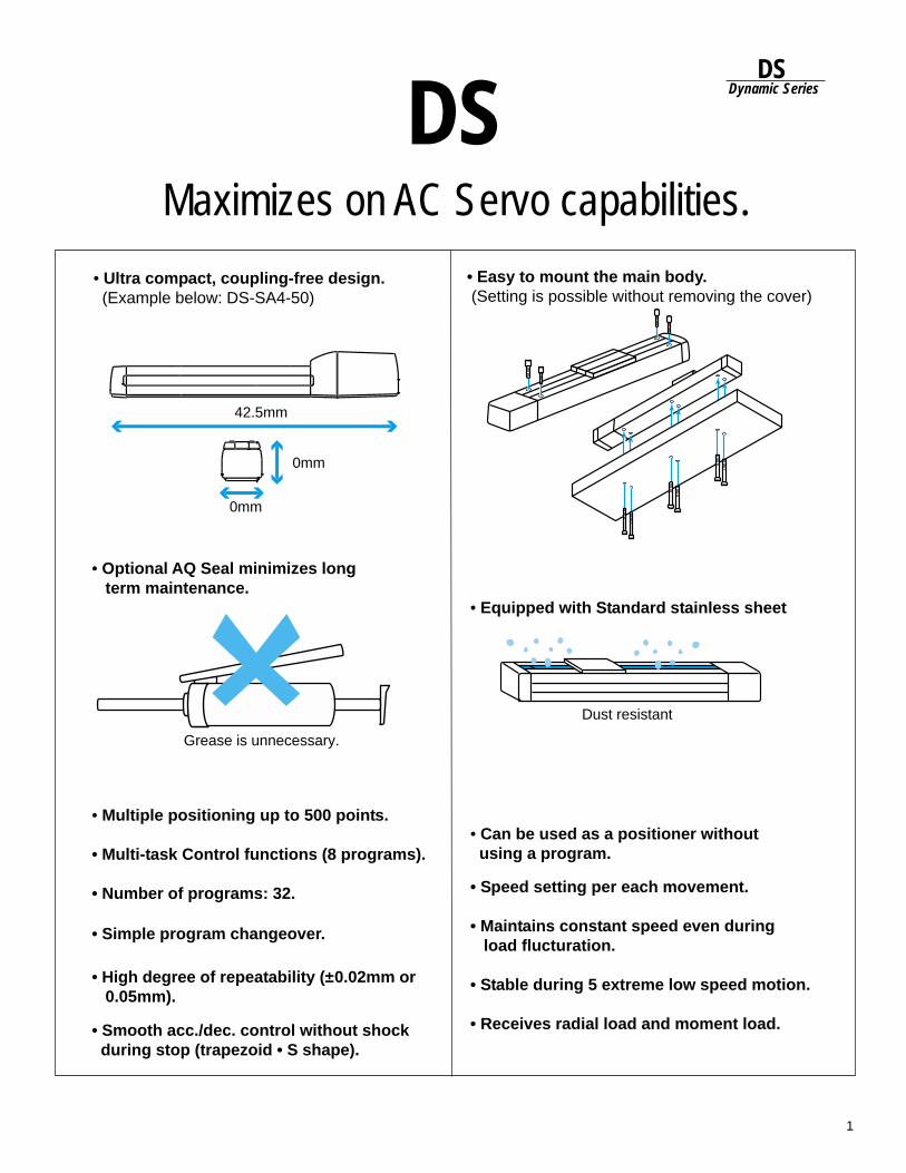
1
DSDynamic Series
• Ultra compact, coupling-free design. (Example below: DS-SA4-50)
• Multiple positioning up to 500 points.
• Multi-task Control functions (8 programs).
• Number of programs: 32.
• Can be used as a positioner without using a program.
42.5mm
0mm
0mm
• Easy to mount the main body. (Setting is possible without removing the cover)
• Optional AQ Seal minimizes long term maintenance.
Grease is unnecessary.
• Equipped with Standard stainless sheet
Dust resistant
DSMaximizes on AC Servo capabilities.
• Simple program changeover.
• High degree of repeatability (±0.02mm or 0.05mm).
• Smooth acc./dec. control without shock during stop (trapezoid • S shape).
• Speed setting per each movement.
• Maintains constant speed even during load flucturation.
• Stable during 5 extreme low speed motion.
• Receives radial load and moment load.
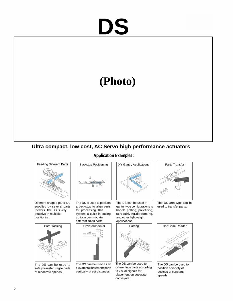
2
Application Examples:
Feeding Different Parts Backstop Positioning Parts TransferXY Gantry Applications
Different shaped parts aresupplied by several partsfeeders. The DS is veryeffective in multiplepositioning.
The DS is used to positiona backstop to align partsfor processing. Thissystem is quick in settingup to accommodatedifferent sized parts.
The DS can be used ingantry-type configurations tohandle potting, palletizing,screwdriving,dispensing,and other lightweightapplications.
The DS arm type can beused to transfer parts.
Part Stacking Bar Code ReaderElevator/Indexer Sorting
The DS can be used tosafely transfer fragile partsat moderate speeds.
The DS can be used toposition a variety ofdevices at constantspeeds.
The DS can be used todifferentiate parts accordingto visual signals forplacement on separateconveyors.
The DS can be used as anelevator to increment partsvertically at set distances.
(Photo)
DS
Ultra compact, low cost, AC Servo high performance actuators
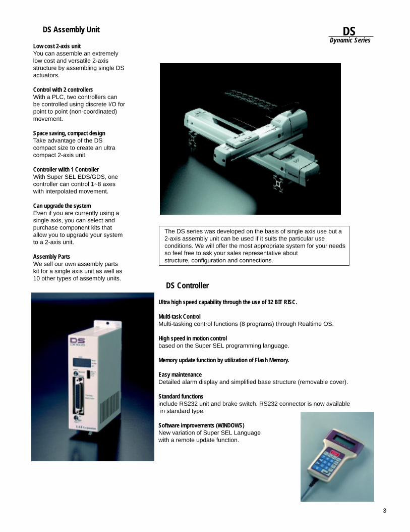
3
DSDynamic Series
The DS series was developed on the basis of single axis use but a2-axis assembly unit can be used if it suits the particular useconditions. We will offer the most appropriate system for your needsso feel free to ask your sales representative aboutstructure, configuration and connections.
DS Assembly Unit
Low cost 2-axis unitYou can assemble an extremelylow cost and versatile 2-axisstructure by assembling single DSactuators.
Control with 2 controllersWith a PLC, two controllers canbe controlled using discrete I/O forpoint to point (non-coordinated)movement.
Space saving, compact designTake advantage of the DScompact size to create an ultracompact 2-axis unit.
Controller wilth 1 ControllerWith Super SEL EDS/GDS, onecontroller can control 1~8 axeswith interpolated movement.
Can upgrade the systemEven if you are currently using asingle axis, you can select andpurchase component kits thatallow you to upgrade your systemto a 2-axis unit.
Assembly PartsWe sell our own assembly partskit for a single axis unit as well as10 other types of assembly units.
DS Controller
Ultra high speed capability through the use of 32 BIT RISC.
Multi-task ControlMulti-tasking control functions (8 programs) through Realtime OS.
High speed in motion controlbased on the Super SEL programming language.
Memory update function by utilization of Flash Memory.
Easy maintenanceDetailed alarm display and simplified base structure (removable cover).
Standard functionsinclude RS232 unit and brake switch. RS232 connector is now available
in standard type.
Software improvements (WINDOWS)New variation of Super SEL Languagewith a remote update function.
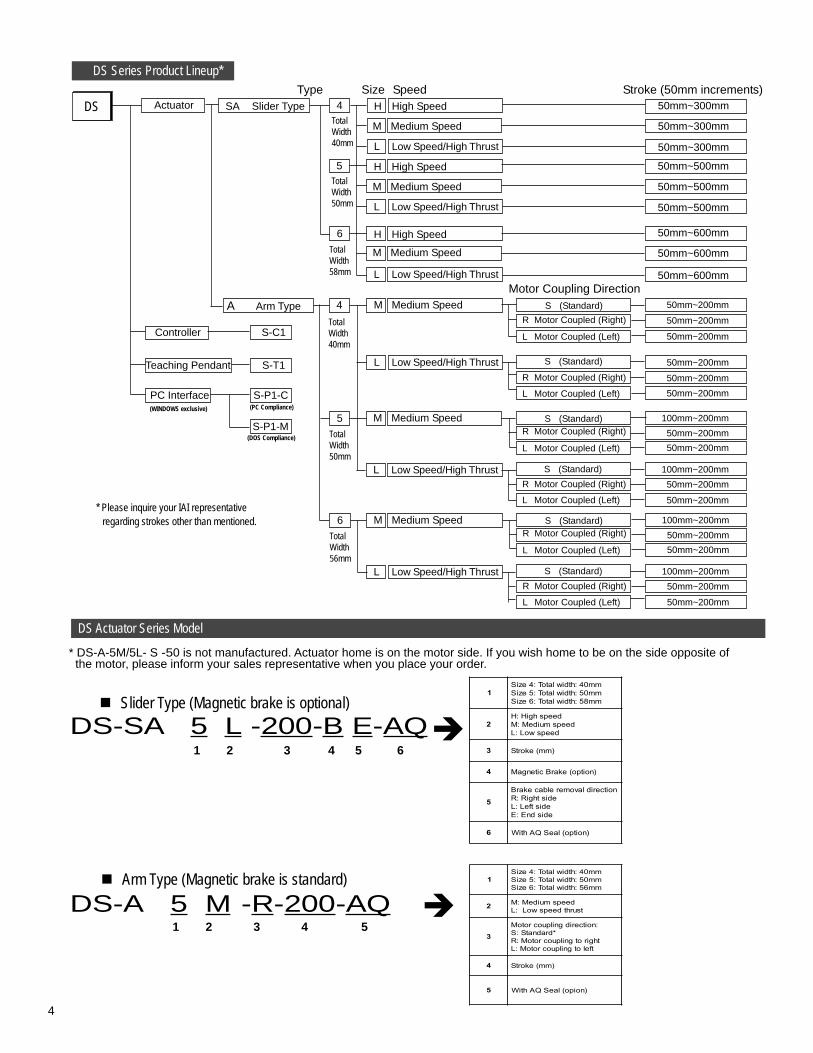
4
DS-SA 5 L -200-B E-AQ
50mm~200mm
50mm~200mmR Motor Coupled (Right)
L Motor Coupled (Left)
S (Standard)
Type Size Speed Stroke (50mm increments)
6
TotalWidth58mm L Low Speed/High Thrust
M Medium Speed
H High Speed
TotalWidth40mm
A Arm Type M Medium Speed4
L Low Speed/High ThrustR Motor Coupled (Right)
L Motor Coupled (Left)
S (Standard)
50mm~600mm
50mm~600mm
50mm~600mm
50mm~200mm
50mm~200mm
50mm~200mm
50mm~200mm
Controller
PC Interface
Teaching Pendant
S-C1
S-T1
S-P1-C
S-P1-M
(WINDOWS exclusive) (PC Compliance)
(DOS Compliance)
DS Series Product Lineup*
5
TotalWidth50mm
R Motor Coupled (Right)
L Motor Coupled (Left)
S (Standard)M Medium Speed
L Low Speed/High ThrustR Motor Coupled (Right)
L Motor Coupled (Left)
S (Standard)
100mm~200mm
50mm~200mm
50mm~200mm
100mm~200mm
50mm~200mm
50mm~200mm
6
TotalWidth56mm
R Motor Coupled (Right)
L Motor Coupled (Left)
S (Standard)M Medium Speed
L Low Speed/High ThrustR Motor Coupled (Right)
L Motor Coupled (Left)
S (Standard)
100mm~200mm
50mm~200mm
50mm~200mm
100mm~200mm
50mm~200mm
50mm~200mm
TotalWidth50mm
50mm~500mm
L Low Speed/High Thrust 50mm~500mm
50mm~500mmM Medium Speed
H High Speed5
TotalWidth40mm
50mm~300mm
L Low Speed/High Thrust 50mm~300mm
50mm~300mmM Medium Speed
H High Speed4ActuatorDS SA Slider Type
Motor Coupling Direction
* DS-A-5M/5L- S -50 is not manufactured. Actuator home is on the motor side. If you wish home to be on the side opposite of the motor, please inform your sales representative when you place your order.
DS Actuator Series Model
Arm Type (Magnetic brake is standard)
DS-A 5 M--R-200-AQ1 2 3 4 5
Slider Type (Magnetic brake is optional)
1 2 3 4 5 6
* Please inquire your IAI representative regarding strokes other than mentioned.
1mm04:htdiwlatoT:4eziSmm05:htdiwlatoT:5eziSmm85:htdiwlatoT:6eziS
2deepshgiH:H
deepsmuideM:MdeepswoL:L
3 )mm(ekortS
4 ekarBcitengaM )noitpo(
5noitceridlavomerelbacekarB
edisthgiR:RedistfeL:LedisdnE:E
6 )noitpo(laeSQAhtiW
1mm04:htdiwlatoT:4eziSmm05:htdiwlatoT:5eziSmm65:htdiwlatoT:6eziS
2 deepsmuideM:MtsurhtdeepswoL:L
3:noitceridgnilpuocrotoM
*dradnatS:SthgirotgnilpuocrotoM:R
tfelotgnilpuocrotoM:L
4 )mm(ekortS
5 )noipo(laeSQAhtiW
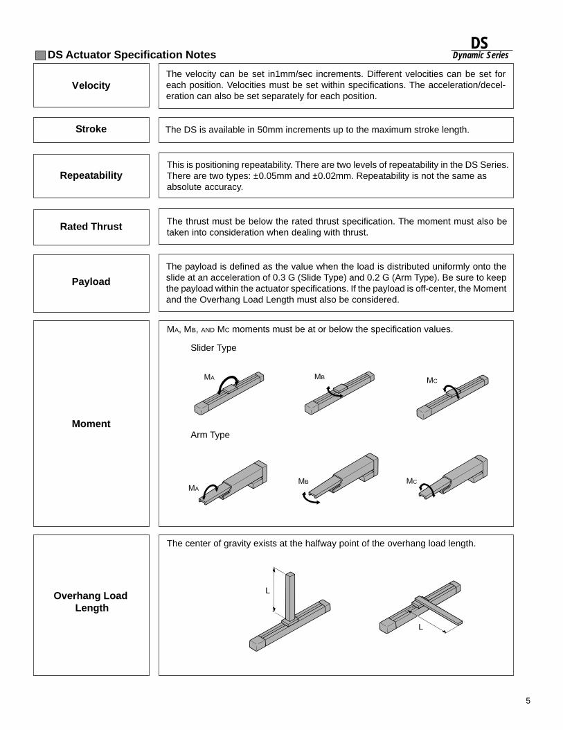
5
DSDynamic Series
The center of gravity exists at the halfway point of the overhang load length.
MA, MB, AND MC moments must be at or below the specification values.
The payload is defined as the value when the load is distributed uniformly onto theslide at an acceleration of 0.3 G (Slide Type) and 0.2 G (Arm Type). Be sure to keepthe payload within the actuator specifications. If the payload is off-center, the Momentand the Overhang Load Length must also be considered.
Payload
The thrust must be below the rated thrust specification. The moment must also betaken into consideration when dealing with thrust.
Rated Thrust
Moment
Overhang Load Length
This is positioning repeatability. There are two levels of repeatability in the DS Series.There are two types: ±0.05mm and ±0.02mm. Repeatability is not the same asabsolute accuracy.
Repeatability
DS Actuator Specification Notes
Stroke The DS is available in 50mm increments up to the maximum stroke length.
VelocityThe velocity can be set in1mm/sec increments. Different velocities can be set foreach position. Velocities must be set within specifications. The acceleration/decel-eration can also be set separately for each position.
MA MB MC
MAMB MC
L
L
Slider Type
Arm Type

6
DS-SA• Positioning is achieved by the slide which
travels along the stroke length.
• Driven by an AC servo motor andballscrew for multiple positioning with ahigh degree of repeatability (±0.02mm or±0.05mm).
• Can also be used as a vertical axis (brake option available).
• A stainless steel sheet prevents dust fromentering the actuator. Rigidity ismaintained because the guidemechanism is integrated into the base.
• The DS actuator comes in 3 types, a58mm width and a 40mm width. All arecompact, providing flexibility in systemlayout. • SA4 (Total width: 40mm) • SA5 (Total width: 50mm) • SA6 (Toral width: 58mm)
Slider Type
DS Slider TypePhoto
Slider
Stainless sheet
Aluminum cover
Steel Ball
Base (guide)
Ballscrew
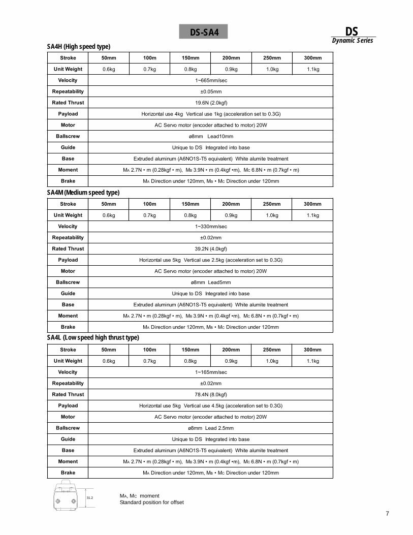
7
DSDynamic Series
SA4M (Medium speed type)
SA4L (Low speed high thrust type)
MA, MC momentStandard position for offset
SA4H (High speed type)
DS-SA4
31.2
ekortS mm05 m001 mm051 mm002 mm052 mm003
thgieWtinU gk6.0 gk7.0 gk8.0 gk9.0 gk0.1 gk1.1
yticoleV ces/mm566~1
ytilibataepeR mm50.0±
tsurhTdetaR )fgk0.2(N6.91
daolyaP )G3.0ottesnoitarelecca(gk1esulacitreVgk4esulatnoziroH
rotoM W02)rotomotdehcattaredocne(rotomovreSCA
wercsllaB mm01daeLmm8ø
ediuG esabotnidetargetnISDoteuqinU
esaB tnemtaertetimulaetihW)tnelaviuqe5T-S1ON6A(munimuladedurtxE
tnemoM MA M,)m•fgk82.0(m•N7.2 B M,)m•fgk4.0(m•N9.3 C )m•fgk7.0(m•N8.6
ekarB MA M,mm021rednunoitceriD B M• C mm021rednunoitceriD
ekortS mm05 m001 mm051 mm002 mm052 mm003
thgieWtinU gk6.0 gk7.0 gk8.0 gk9.0 gk0.1 gk1.1
yticoleV ces/mm033~1
ytilibataepeR mm20.0±
tsurhTdetaR )fgk0.4(N2.93
daolyaP )G3.0ottesnoitarelecca(gk5.2esulacitreVgk5esulatnoziroH
rotoM W02)rotomotdehcattaredocne(rotomovreSCA
wercsllaB mm5daeLmm8ø
ediuG esabotnidetargetnISDoteuqinU
esaB tnemtaertetimulaetihW)tnelaviuqe5T-S1ON6A(munimuladedurtxE
tnemoM MA M,)m•fgk82.0(m•N7.2 B M,)m•fgk4.0(m•N9.3 C )m•fgk7.0(m•N8.6
ekarB MA M,mm021rednunoitceriD B M• C mm021rednunoitceriD
ekortS mm05 m001 mm051 mm002 mm052 mm003
thgieWtinU gk6.0 gk7.0 gk8.0 gk9.0 gk0.1 gk1.1
yticoleV ces/mm561~1
ytilibataepeR mm20.0±
tsurhTdetaR )fgk0.8(N4.87
daolyaP )G3.0ottesnoitarelecca(gk5.4esulacitreVgk5esulatnoziroH
rotoM W02)rotomotdehcattaredocne(rotomovreSCA
wercsllaB mm5.2daeLmm8ø
ediuG esabotnidetargetnISDoteuqinU
esaB tnemtaertetimulaetihW)tnelaviuqe5T-S1ON6A(munimuladedurtxE
tnemoM MA M,)m•fgk82.0(m•N7.2 B M,)m•fgk4.0(m•N9.3 C )m•fgk7.0(m•N8.6
ekarB MA M,mm021rednunoitceriD B M• C mm021rednunoitceriD
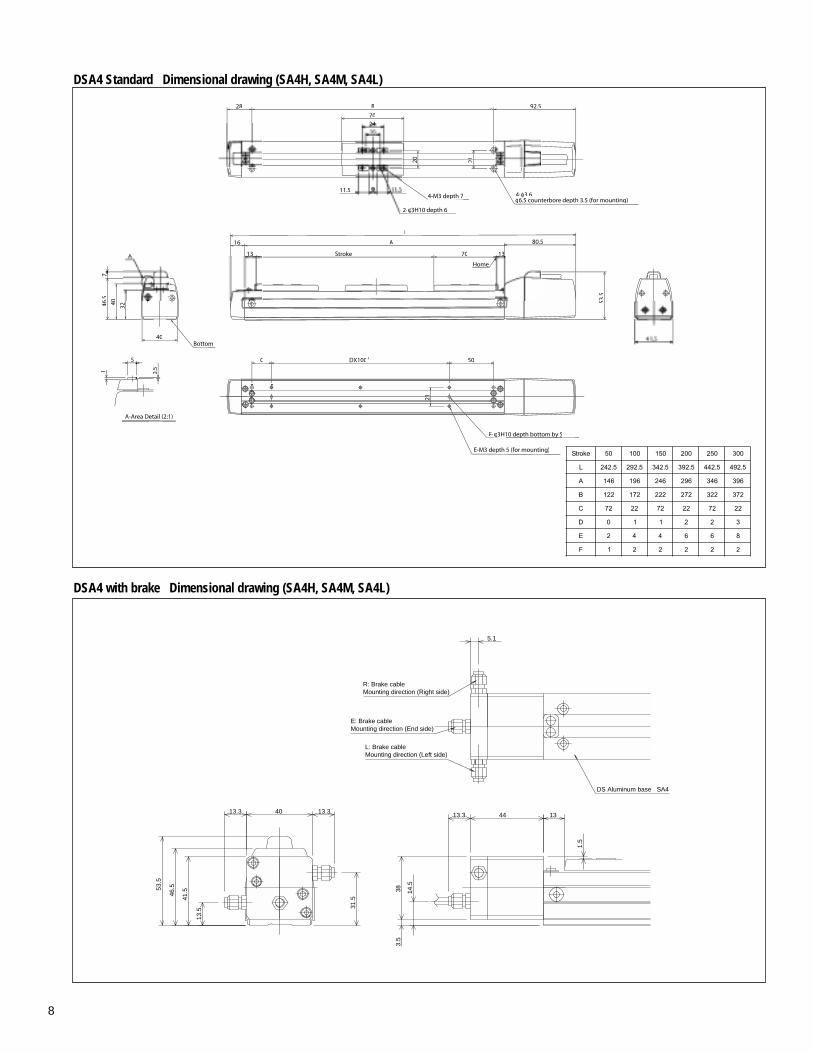
8
DSA4 Standard Dimensional drawing (SA4H, SA4M, SA4L)
DSA4 with brake Dimensional drawing (SA4H, SA4M, SA4L)
5.1
14.5
13.3
383.
5
1.5
31.5
13.344 13
46.553
.5
41.5
40
13.5
13.3
DS Aluminum base SA4
L: Brake cableMounting direction (Left side)
E: Brake cableMounting direction (End side)
R: Brake cableMounting direction (Right side)
21
70
2-φ3H10 depth 6
11.5
φ6.5 counterbore depth 3.5 (for mounting)4- 3.6
28
4-M3 depth 7p
92.5B
200
Bottom
PDX100C
46.5
A
0.5
53.5
50
F-φφ3H10 depth bottom by 5p y
80.5
L
E-M3 depth 5 (for mounting)
A
13 Stroke 70
40
40
A-Area Detail (2:1)
1
ekortS 05 001 051 002 052 003
L 5.242 5.292 5.243 5.293 5.244 5.294
A 641 691 642 692 643 693
B 221 271 222 272 223 273
C 27 22 27 22 27 22
D 0 1 1 2 2 3
E 2 4 4 6 6 8
F 1 2 2 2 2 2
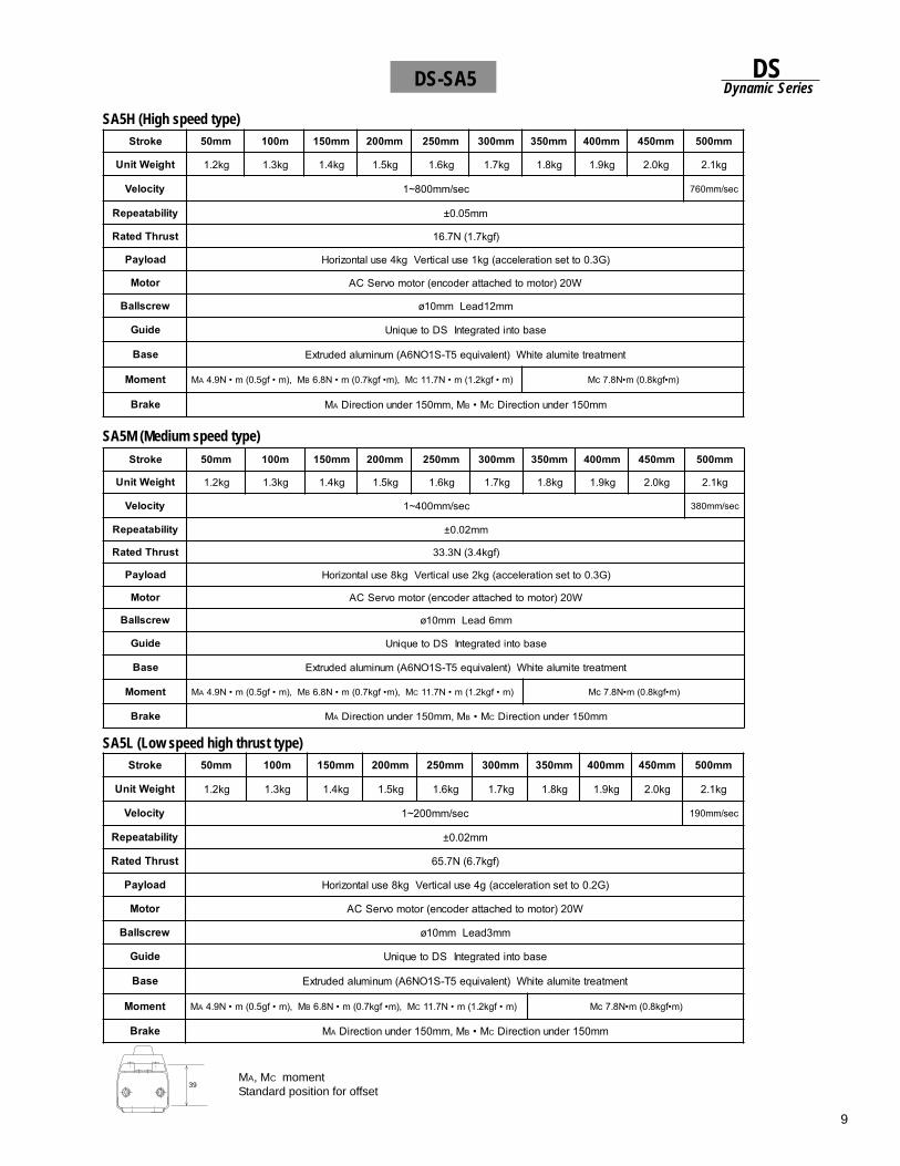
9
DSDynamic Series
SA5M (Medium speed type)
SA5L (Low speed high thrust type)
MA, MC momentStandard position for offset
SA5H (High speed type)
DS-SA5
39
ekortS mm05 m001 mm051 mm002 mm052 mm003 mm053 mm004 mm054 mm005
thgieWtinU gk2.1 gk3.1 gk4.1 gk5.1 gk6.1 gk7.1 gk8.1 gk9.1 gk0.2 gk1.2
yticoleV ces/mm008~1 ces/mm067
ytilibataepeR mm50.0±
tsurhTdetaR )fgk7.1(N7.61
daolyaP )G3.0ottesnoitarelecca(gk1esulacitreVgk4esulatnoziroH
rotoM W02)rotomotdehcattaredocne(rotomovreSCA
wercsllaB mm21daeLmm01ø
ediuG esabotnidetargetnISDoteuqinU
esaB tnemtaertetimulaetihW)tnelaviuqe5T-S1ON6A(munimuladedurtxE
tnemoM MA M,)m•fg5.0(m•N9.4 B M,)m•fgk7.0(m•N8.6 C )m•fgk2.1(m•N7.11 )m•fgk8.0(m•N8.7cM
ekarB MA M,mm051rednunoitceriD B M• C mm051rednunoitceriD
ekortS mm05 m001 mm051 mm002 mm052 mm003 mm053 mm004 mm054 mm005
thgieWtinU gk2.1 gk3.1 gk4.1 gk5.1 gk6.1 gk7.1 gk8.1 gk9.1 gk0.2 gk1.2
yticoleV ces/mm002~1 ces/mm091
ytilibataepeR mm20.0±
tsurhTdetaR )fgk7.6(N7.56
daolyaP )G2.0ottesnoitarelecca(g4esulacitreVgk8esulatnoziroH
rotoM W02)rotomotdehcattaredocne(rotomovreSCA
wercsllaB mm3daeLmm01ø
ediuG esabotnidetargetnISDoteuqinU
esaB tnemtaertetimulaetihW)tnelaviuqe5T-S1ON6A(munimuladedurtxE
tnemoM MA M,)m•fg5.0(m•N9.4 B M,)m•fgk7.0(m•N8.6 C )m•fgk2.1(m•N7.11 )m•fgk8.0(m•N8.7cM
ekarB MA M,mm051rednunoitceriD B M• C mm051rednunoitceriD
ekortS mm05 m001 mm051 mm002 mm052 mm003 mm053 mm004 mm054 mm005
thgieWtinU gk2.1 gk3.1 gk4.1 gk5.1 gk6.1 gk7.1 gk8.1 gk9.1 gk0.2 gk1.2
yticoleV ces/mm004~1 ces/mm083
ytilibataepeR mm20.0±
tsurhTdetaR )fgk4.3(N3.33
daolyaP )G3.0ottesnoitarelecca(gk2esulacitreVgk8esulatnoziroH
rotoM W02)rotomotdehcattaredocne(rotomovreSCA
wercsllaB mm6daeLmm01ø
ediuG esabotnidetargetnISDoteuqinU
esaB tnemtaertetimulaetihW)tnelaviuqe5T-S1ON6A(munimuladedurtxE
tnemoM MA M,)m•fg5.0(m•N9.4 B M,)m•fgk7.0(m•N8.6 C )m•fgk2.1(m•N7.11 )m•fgk8.0(m•N8.7cM
ekarB MA M,mm051rednunoitceriD B M• C mm051rednunoitceriD
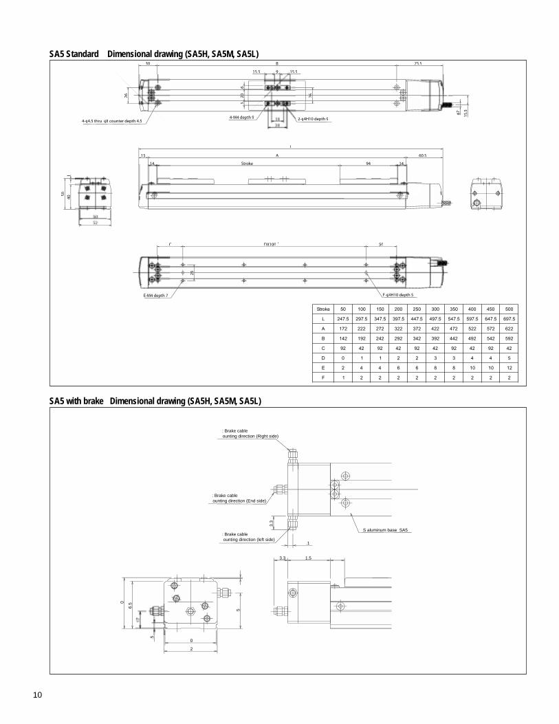
10
SA5 Standard Dimensional drawing (SA5H, SA5M, SA5L)
SA5 with brake Dimensional drawing (SA5H, SA5M, SA5L)
5
.1
3.3
0
0
2
6.5
.5
3.3 1.5
: Brake cableounting direction (left side)
: Brake cableounting direction (End side)
: Brake cableounting direction (Right side)
S aluminum base SA5
ekortS 05 001 051 002 052 003 053 004 054 005
L 5.742 5.792 5.743 5.793 5.744 5.794 5.745 5.795 5.746 5.796
A 271 222 272 223 273 224 274 225 275 226
B 241 291 242 292 243 293 244 294 245 295
C 29 24 29 24 29 24 29 24 29 24
D 0 1 1 2 2 3 3 4 4 5
E 2 4 4 6 6 8 8 01 01 21
F 1 2 2 2 2 2 2 2 2 2
30
4-φ4.5 thru φ8 counter depth 4.526 266
6
15.5115.5
2-φ4H10 depth 94-M4 depth 9dep
75.5
L
A
Stroke 94
60.5
150
40
C DX100 P
F-φ4H10 depth 5
50
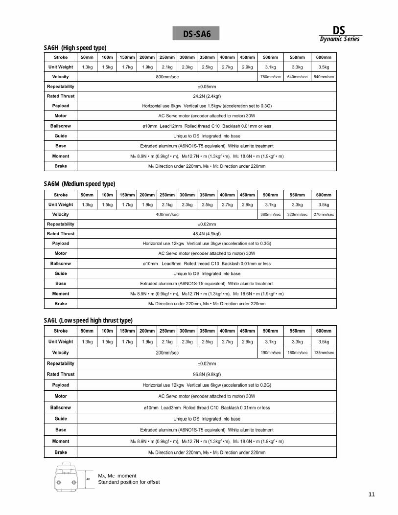
11
DSDynamic Series
SA6H (High speed type)
DS-SA6
SA6M (Medium speed type)
SA6L (Low speed high thrust type)
MA, MC momentStandard position for offset
40
ekortS mm05 m001 mm051 mm002 mm052 mm003 mm053 mm004 mm054 mm005 mm055 mm006
thgieWtinU gk3.1 gk5.1 gk7.1 gk9.1 gk1.2 gk3.2 gk5.2 gk7.2 gk9.2 gk1.3 gk3.3 gk5.3
yticoleV ces/mm008 ces/mm067 ces/mm046 ces/mm045
ytilibataepeR mm50.0±
tsurhTdetaR )fgk4.2(N2.42
daolyaP )G3.0ottesnoitarelecca(wgk5.1esulacitreVwgk6esulatnoziroH
rotoM W03)rotomotdehcattaredocne(rotomovreSCA
wercsllaB sselromm10.0hsalkcaB01CdaerhtdelloRmm21daeLmm01ø
ediuG esabotnidetargetnISDoteuqinU
esaB tnemtaertetimulaetihW)tnelaviuqe5T-S1ON6A(munimuladedurtxE
tnemoM MA M,)m•fgk9.0(m•N9.8 B M,)m•fgk3.1(m•N7.21 C )m•fgk9.1(m•N6.81
ekarB MA M,mm022rednunoitceriD B M• C mm022rednunoitceriD
ekortS mm05 m001 mm051 mm002 mm052 mm003 mm053 mm004 mm054 mm005 mm055 mm006
thgieWtinU gk3.1 gk5.1 gk7.1 gk9.1 gk1.2 gk3.2 gk5.2 gk7.2 gk9.2 gk1.3 gk3.3 gk5.3
yticoleV ces/mm004 ces/mm083 ces/mm023 ces/mm072
ytilibataepeR mm20.0±
tsurhTdetaR )fgk9.4(N4.84
daolyaP )G3.0ottesnoitarelecca(wgk3esulacitreVwgk21esulatnoziroH
rotoM W03)rotomotdehcattaredocne(rotomovreSCA
wercsllaB sselromm10.0hsalkcaB01CdaerhtdelloRmm6daeLmm01ø
ediuG esabotnidetargetnISDoteuqinU
esaB tnemtaertetimulaetihW)tnelaviuqe5T-S1ON6A(munimuladedurtxE
tnemoM MA M,)m•fgk9.0(m•N9.8 B M,)m•fgk3.1(m•N7.21 C )m•fgk9.1(m•N6.81
ekarB MA M,mm022rednunoitceriD B M• C mm022rednunoitceriD
ekortS mm05 m001 mm051 mm002 mm052 mm003 mm053 mm004 mm054 mm005 mm055 mm006
thgieWtinU gk3.1 gk5.1 gk7.1 gk9.1 gk1.2 gk3.2 gk5.2 gk7.2 gk9.2 gk1.3 gk3.3 gk5.3
yticoleV ces/mm002 ces/mm091 ces/mm061 ces/mm531
ytilibataepeR mm20.0±
tsurhTdetaR )fgk8.9(N8.69
daolyaP )G2.0ottesnoitarelecca(wgk6esulacitreVwgk21esulatnoziroH
rotoM W03)rotomotdehcattaredocne(rotomovreSCA
wercsllaB sselromm10.0hsalkcaB01CdaerhtdelloRmm3daeLmm01ø
ediuG esabotnidetargetnISDoteuqinU
esaB tnemtaertetimulaetihW)tnelaviuqe5T-S1ON6A(munimuladedurtxE
tnemoM MA M,)m•fgk9.0(m•N9.8 B M,)m•fgk3.1(m•N7.21 C )m•fgk9.1(m•N6.81
ekarB MA M,mm022rednunoitceriD B M• C mm022rednunoitceriD
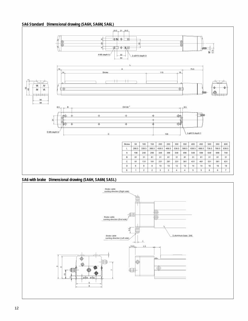
12
SA6 Standard Dimensional drawing (SA6H, SA6M, SA6L)
SA6 with brake Dimensional drawing (SA6H, SA6M, SASL)
0
1.5
7
3
8
5
.1
3.3
: Brake cableounting direction (Left side)
: Brake cableounting direction (End side)
S aluminum base SA6
: Brake cableounting direction (Right side)
ekortS 05 001 051 002 052 003 053 004 054 005 055 006
L 5.882 5.833 5.883 5.834 5.884 5.835 5.885 5.836 5.886 5.837 5.887 5.838
A 891 842 892 843 893 844 894 845 895 846 896 847
B 18 13 18 13 18 13 18 13 18 13 18 13
C 18 131 181 132 182 133 183 134 184 135 185 136
D 6 8 8 01 01 21 21 41 41 61 61 81
E 1 2 2 3 3 4 4 5 5 6 6 7
φ
3-φ4H10 depth 5
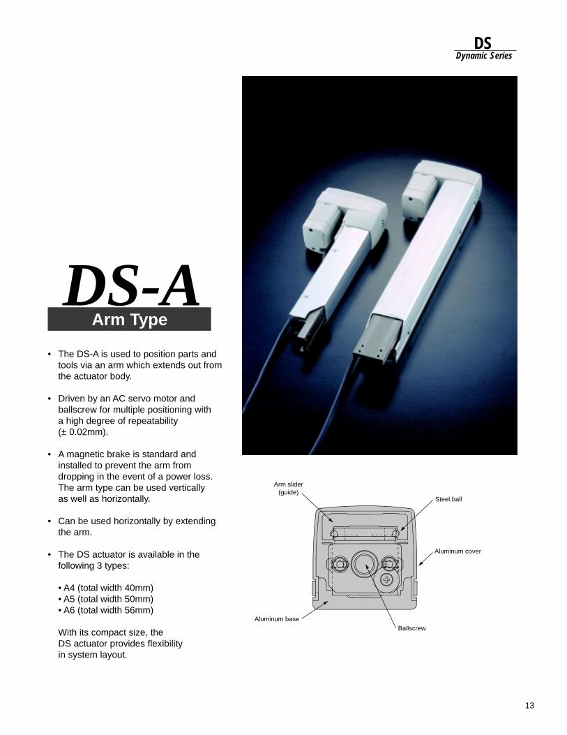
13
DSDynamic Series
• The DS-A is used to position parts andtools via an arm which extends out fromthe actuator body.
• Driven by an AC servo motor andballscrew for multiple positioning witha high degree of repeatability(± 0.02mm).
• A magnetic brake is standard andinstalled to prevent the arm fromdropping in the event of a power loss.The arm type can be used verticallyas well as horizontally.
• Can be used horizontally by extendingthe arm.
• The DS actuator is available in thefollowing 3 types:
• A4 (total width 40mm)• A5 (total width 50mm)• A6 (total width 56mm)
With its compact size, theDS actuator provides flexibilityin system layout.
Arm TypeDS-A
Aluminum cover
Arm slider(guide)
Aluminum baseBallscrew
Steel ball
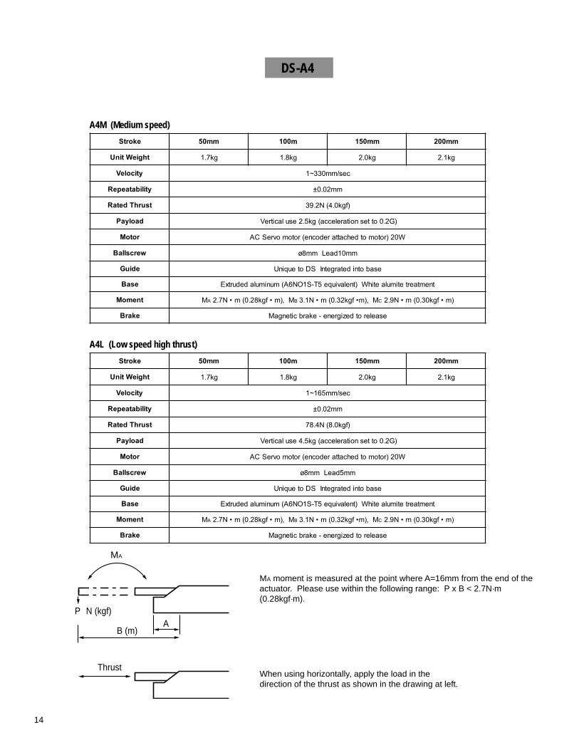
14
A4M (Medium speed)
DS-A4
A4L (Low speed high thrust)
When using horizontally, apply the load in thedirection of the thrust as shown in the drawing at left.
MA moment is measured at the point where A=16mm from the end of theactuator. Please use within the following range: P x B < 2.7N·m(0.28kgf·m).
Thrust
MA
N (kgf)P
B (m)A
ekortS mm05 m001 mm051 mm002
thgieWtinU gk7.1 gk8.1 gk0.2 gk1.2
yticoleV ces/mm033~1
ytilibataepeR mm20.0±
tsurhTdetaR )fgk0.4(N2.93
daolyaP )G2.0ottesnoitarelecca(gk5.2esulacitreV
rotoM W02)rotomotdehcattaredocne(rotomovreSCA
wercsllaB mm01daeLmm8ø
ediuG esabotnidetargetnISDoteuqinU
esaB tnemtaertetimulaetihW)tnelaviuqe5T-S1ON6A(munimuladedurtxE
tnemoM MA M,)m•fgk82.0(m•N7.2 B M,)m•fgk23.0(m•N1.3 C )m•fgk03.0(m•N9.2
ekarB esaelerotdezigrene-ekarbcitengaM
ekortS mm05 m001 mm051 mm002
thgieWtinU gk7.1 gk8.1 gk0.2 gk1.2
yticoleV ces/mm561~1
ytilibataepeR mm20.0±
tsurhTdetaR )fgk0.8(N4.87
daolyaP )G2.0ottesnoitarelecca(gk5.4esulacitreV
rotoM W02)rotomotdehcattaredocne(rotomovreSCA
wercsllaB mm5daeLmm8ø
ediuG esabotnidetargetnISDoteuqinU
esaB tnemtaertetimulaetihW)tnelaviuqe5T-S1ON6A(munimuladedurtxE
tnemoM MA M,)m•fgk82.0(m•N7.2 B M,)m•fgk23.0(m•N1.3 C )m•fgk03.0(m•N9.2
ekarB esaelerotdezigrene-ekarbcitengaM
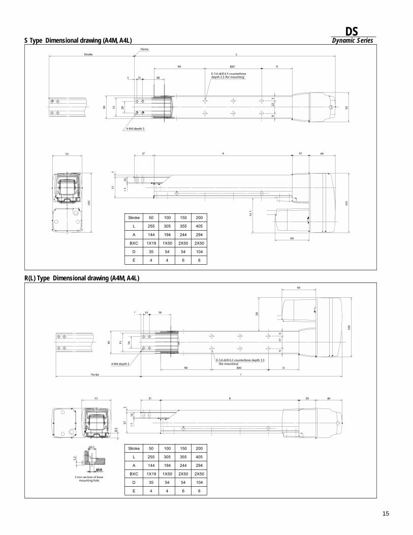
15
DSDynamic Series
105
60
99
22
D
30 46
38
BXC90(for mounting)
L
5
4-M4 depth 5
2040 33
Stroke
35 A
2.2
Cross section of base mounting hole
52
373
1.5
10
59
52
46
9
D
L
BXC
229
30
105
60
38
90
Home
10
35 A
Stroke
5
33 20
4-M4 depth 5
40
1.537
3
E-3.6 drill 6.5 counterboredepth 3.3 (for mounting)
52
105
61.5
S Type Dimensional drawing (A4M, A4L)
R(L) Type Dimensional drawing (A4M, A4L)
ekortS 05 001 051 002
L 552 503 553 504
A 441 491 442 492
CXB 91X1 05X1 05X2 05X2
D 53 45 45 401
E 4 4 6 6
ekortS 05 001 051 002
L 552 503 553 504
A 441 491 442 492
CXB 91X1 05X1 05X2 05X2
D 53 45 45 401
E 4 4 6 6
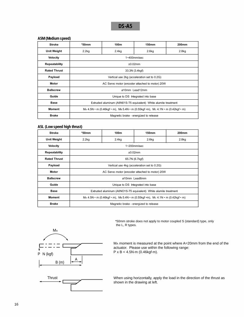
16
A5L (Low speed high thrust)
MA moment is measured at the point where A=20mm from the end of theactuator. Please use within the following range:P x B < 4.5N·m (0.46kgf·m).
When using horizontally, apply the load in the direction of the thrust asshown in the drawing at left.
*50mm stroke does not apply to motor coupled S (standard) type, only the L, R types.
Thrust
MA
N (kgf)P
B (m)A
A5M (Medium speed)
DS-A5
ekortS mm05* m001 mm051 mm002
thgieWtinU gk2.2 gk4.2 gk6.2 gk8.2
yticoleV ces/mm004~1
ytilibataepeR mm20.0±
tsurhTdetaR )fgk4.3(N3.33
daolyaP )G2.0ottesnoitarelecca(gk2esulacitreV
rotoM W02)rotomotdehcattaredocne(rotomovreSCA
wercsllaB mm21daeLmm01ø
ediuG esabotnidetargetnISDoteuqinU
esaB tnemtaertetimulaetihW)tnelaviuqe5T-S10N6A(munimuladedurtxE
tnemoM MA M,)m•fgk64.0(m•N5.4 B M,)m•fgk55.0(m•N4.5 C )m•fgk24.0(m•N1.4
ekarB esaelerotdezigrene-ekarbcitengaM
ekortS mm05* m001 mm051 mm002
thgieWtinU gk2.2 gk4.2 gk6.2 gk8.2
yticoleV ces/mm002~1
ytilibataepeR mm20.0±
tsurhTdetaR )fgk7.6(N7.56
daolyaP )G2.0ottesnoitarelecca(gk4esulacitreV
rotoM W02)rotomotdehcattaredocne(rotomovreSCA
wercsllaB mm6daeLmm01ø
ediuG esabotnidetargetnISDoteuqinU
esaB tnemtaertetimulaetihW)tnelaviuqe5T-S1ON6A(munimuladedurtxE
tnemoM MA M,)m•fgk64.0(m•N5.4 B M,)m•fgk55.0(m•N4.5 C )m•fgk24.0(m•N1.4
ekarB esaelerotdezigrene-ekarbcitengaM
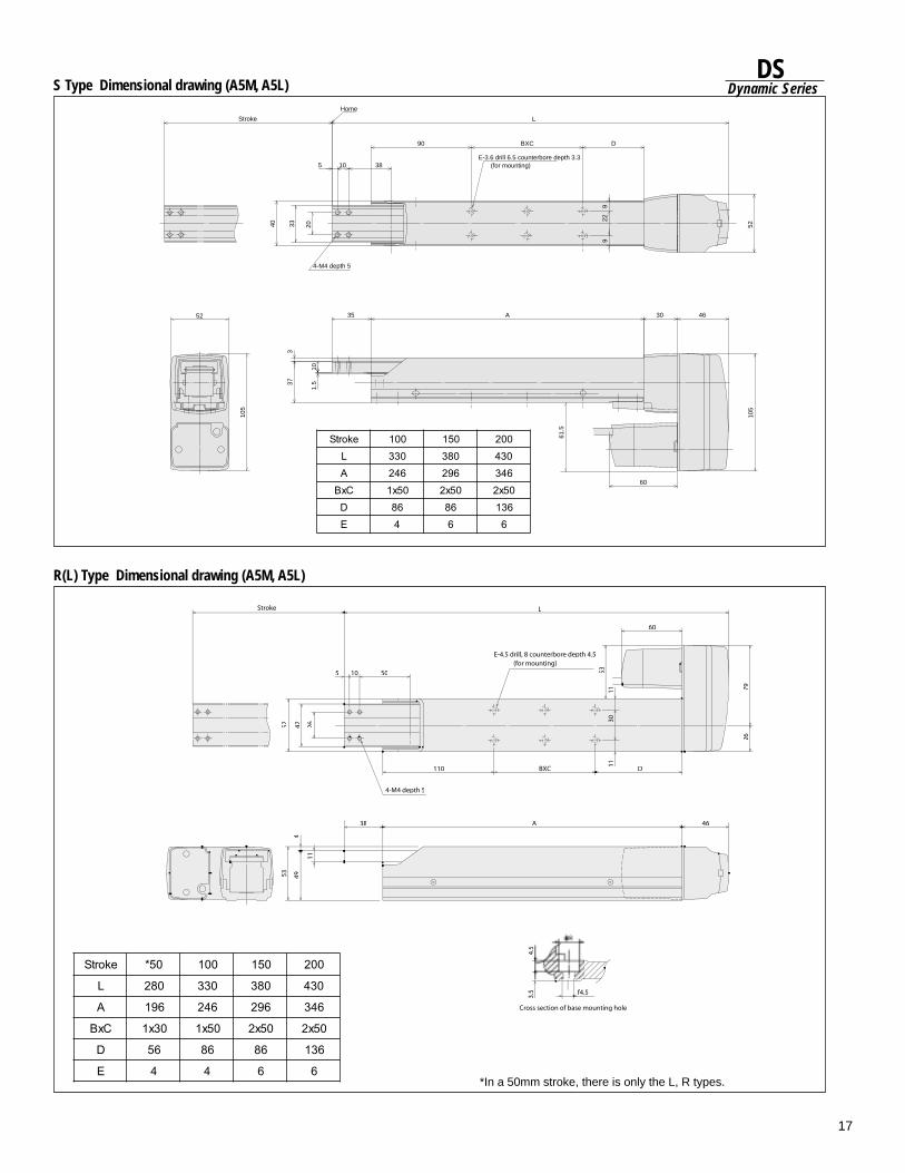
17
DSDynamic Series
7926
L
60
30
BXC D
11
46A
4.5
3.5
5 50
110
4252
38
449
26
53
Cross section of base mounting hole
4-M4 depth 5
Stroke
E-4.5 drill, 8 counterbore depth 4.5 (for mounting)
f
S Type Dimensional drawing (A5M, A5L)
R(L) Type Dimensional drawing (A5M, A5L)
*In a 50mm stroke, there is only the L, R types.
ekortS 05* 001 051 002
L 082 033 083 034
A 691 642 692 643
CxB 03x1 05x1 05x2 05x2
D 65 68 68 631
E 4 4 6 6
52
46
9
D
L
BXC
229
30
105
60
38
90
10
35 A
5
33 2040
1.537
3
1052
105
61.5
4-M4 depth 5
Stroke
Home
E-3.6 drill 6.5 counterbore depth 3.3 (for mounting)
ekortS 001 051 002L 033 083 034A 642 692 643CxB 05x1 05x2 05x2D 68 68 631E 4 6 6
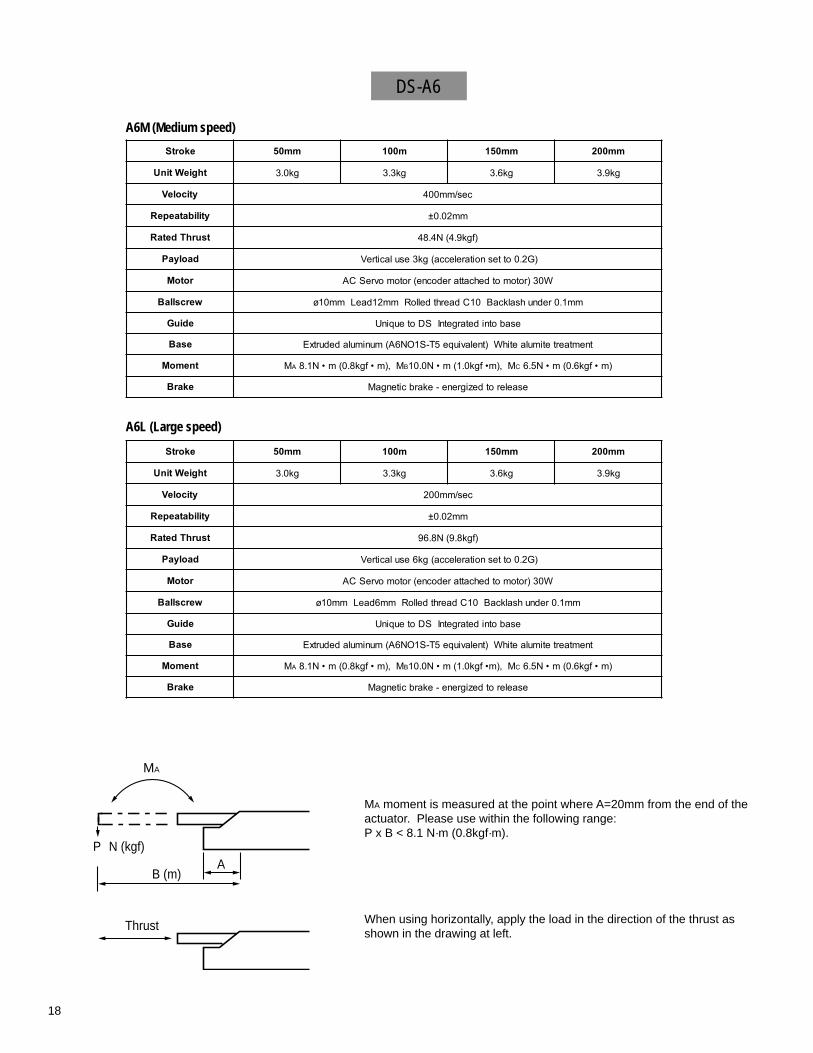
18
A6M (Medium speed)
DS-A6
A6L (Large speed)
MA moment is measured at the point where A=20mm from the end of theactuator. Please use within the following range:P x B < 8.1 N·m (0.8kgf·m).
When using horizontally, apply the load in the direction of the thrust asshown in the drawing at left.
Thrust
MA
N (kgf)P
B (m)A
ekortS mm05 m001 mm051 mm002
thgieWtinU gk0.3 gk3.3 gk6.3 gk9.3
yticoleV ces/mm004
ytilibataepeR mm20.0±
tsurhTdetaR )fgk9.4(N4.84
daolyaP )G2.0ottesnoitarelecca(gk3esulacitreV
rotoM W03)rotomotdehcattaredocne(rotomovreSCA
wercsllaB mm1.0rednuhsalkcaB01CdaerhtdelloRmm21daeLmm01ø
ediuG esabotnidetargetnISDoteuqinU
esaB tnemtaertetimulaetihW)tnelaviuqe5T-S1ON6A(munimuladedurtxE
tnemoM MA M,)m•fgk8.0(m•N1.8 B M,)m•fgk0.1(m•N0.01 C )m•fgk6.0(m•N5.6
ekarB esaelerotdezigrene-ekarbcitengaM
ekortS mm05 m001 mm051 mm002
thgieWtinU gk0.3 gk3.3 gk6.3 gk9.3
yticoleV ces/mm002
ytilibataepeR mm20.0±
tsurhTdetaR )fgk8.9(N8.69
daolyaP )G2.0ottesnoitarelecca(gk6esulacitreV
rotoM W03)rotomotdehcattaredocne(rotomovreSCA
wercsllaB mm1.0rednuhsalkcaB01CdaerhtdelloRmm6daeLmm01ø
ediuG esabotnidetargetnISDoteuqinU
esaB tnemtaertetimulaetihW)tnelaviuqe5T-S1ON6A(munimuladedurtxE
tnemoM MA M,)m•fgk8.0(m•N1.8 B M,)m•fgk0.1(m•N0.01 C )m•fgk6.0(m•N5.6
ekarB esaelerotdezigrene-ekarbcitengaM
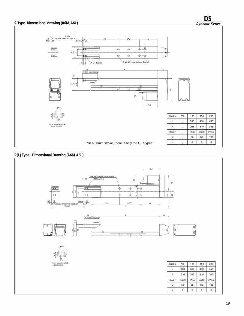
19
DSDynamic Series
3.3ME SE
(in case with lubricant seal: 3) Stroke
Home ME3
56
1313
49 31
5 10 4-M4 depth 6 E-φ6, φ9, 5 counterbore depth 7
130 BXCP DL
46
107
A3857
53.5
3.5
14.5
70 (Work mounting range)
50
75.5φ9.5
φ6
47
Base mounting hole Cross section
30
S Type Dimensional drawing (A6M, A6L)
φ9.5
φ6
74
57
14.5
53.5
3.5
38 A 4670 (work mounting range)
LDBXCP130
SEHome33.3
ME SE(In case with lubricant seal: 3)
Stroke
56 49 31
5 10 4-M4 depth 6E-φ6, φ9, 5depth counterbore 7
51
75.5
7928
Base mounting holecross section
1313
30
R(L) Type Dimensional Drawing (A6M, A6L)
*In a 50mm stroke, there is only the L, R types.
ekortS 05* 001 051 002
L _ 053 004 054
A _ 662 613 663
CXB P _ 05X1 05X2 05X2
D _ 68 68 631
E _ 4 6 6
ekortS 05* 001 051 002
L 003 053 004 054
A 612 662 613 663
CXB P 03X1 05X1 05X2 05X2
D 65 68 68 631
E 4 4 6 6
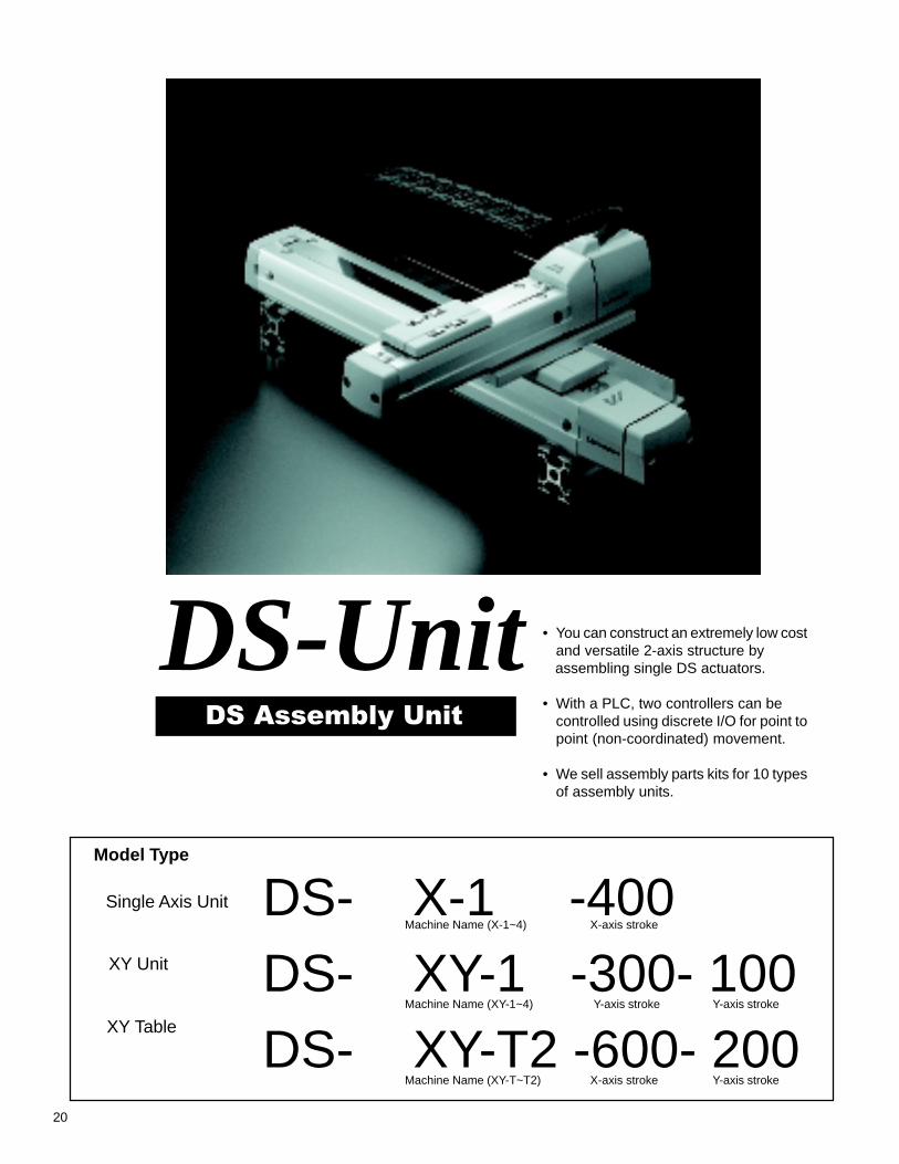
20
DS-UnitDS Assembly Unit
• You can construct an extremely low costand versatile 2-axis structure by
assembling single DS actuators.
• With a PLC, two controllers can becontrolled using discrete I/O for point topoint (non-coordinated) movement.
• We sell assembly parts kits for 10 typesof assembly units.
DS Assembly Unit
XY Unit
XY Table
DS- X-1 -400DS- XY-1 -300- 100DS- XY-T2 -600- 200
Machine Name (X-1~4)
Machine Name (XY-1~4)
Machine Name (XY-T~T2)
X-axis stroke
Y-axis stroke
X-axis stroke Y-axis stroke
Y-axis stroke
Model Type
Single Axis Unit

21
DSDynamic Series
DS-SA5-50~400
Single Axis Unit
X-1
X-2
X-3
X-4
XY Table
XY-T
XY-T2
Single Axis Unit
XY-1
XY-2
XY-3
XY-4
DS-SA5-50~400
DS-SA6-50~600
DS-SA6-50~600
DS Aluminum Base Assembly Unit Product Structure
X: Axis DS-SA5-50~400Y: Axis DS-SA4-50~100
X: Axis DS-SA5-50~400Y: Axis DS-SA4-50~100
X: Axis DS-SA6-50~600Y: Axis DS-SA5-50~150
X: Axis DS-SA6-50~600Y: Axis DS-SA5-50~150
X: Axis DS-SA5-50~400Y: Axis DS-SA4-50~150
X: Axis DS-SA6-50~600Y: Axis DS-SA5-50~200
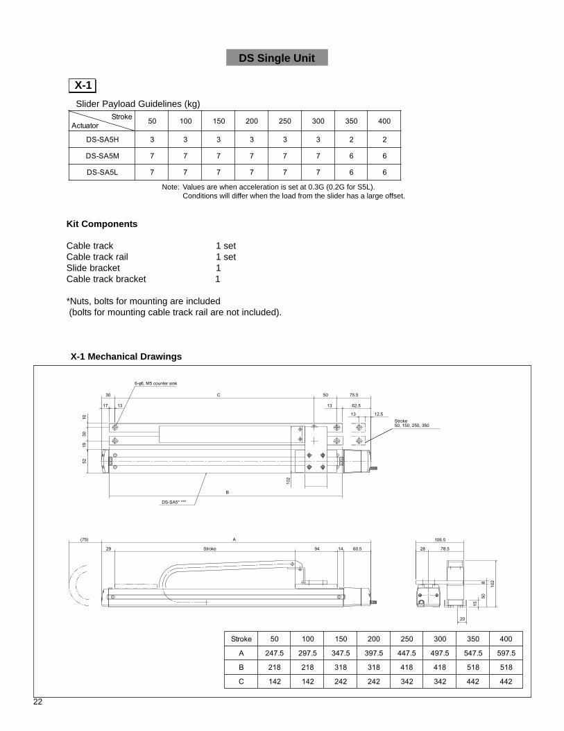
22
ekortSrotautcA 05 001 051 002 052 003 053 004
H5AS-SD 3 3 3 3 3 3 2 2
M5AS-SD 7 7 7 7 7 7 6 6
L5AS-SD 7 7 7 7 7 7 6 6
Slider Payload Guidelines (kg)
Note: Values are when acceleration is set at 0.3G (0.2G for S5L).Conditions will differ when the load from the slider has a large offset.
Kit Components
Cable track 1 setCable track rail 1 setSlide bracket 1Cable track bracket 1
*Nuts, bolts for mounting are included (bolts for mounting cable track rail are not included).
X-1 Mechanical Drawings
DS Single Unit
X-1
ekortS 05 001 051 002 052 003 053 004
A 5.742 5.792 5.743 5.793 5.744 5.794 5.745 5.795
B 812 812 813 813 814 814 815 815
C 241 241 242 242 243 243 244 244
30
17 13
1030
19
6-φ6, M5 counter sink
50 75.5
13 62.5
13 12.5
B
106.5
60.5149429 Stroke
A(75)
28 78.5
20
C
52
Stroke50, 150, 250, 350
DS-SA5* ***
102
102
508
15
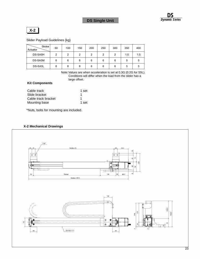
23
DSDynamic Series
Slider Payload Guidelines (kg)
Note:Values are when acceleration is set at 0.3G (0.2G for S5L).Conditions will differ when the load from the slider has alarge offset.
Kit Components
Cable track 1 setSlide bracket 1Cable track bracket 1Mounting base 1 set
X-2 Mechanical Drawings
X-2
*Nuts, bolts for mounting are included.
DS Single Unit
20 20 Stroke+72 65.5
29
40 40
50
Stroke 94 60.5
Stroke+197.5
1041
8
5158
109
2-φ7
52
DS-SA5*-***
138
5
115
2
14
5110
5.3
156.
3
ekortSrotautcA 05 001 051 002 052 003 053 004
H5AS-SD 2 2 2 2 2 2 5.1 5.1
M5AS-SD 6 6 6 6 6 6 5 5
L5AS-SD 6 6 6 6 6 6 5 5

24
Slider Payload Guidelines (kg)
Note: Values are when acceleration is set at 0.3G (0.2G for SA6L).Conditions will differ when the load from the slider has a large offset.
Kit Components
Cable track 1 setCable track rail 1 setSlide bracket 1Cable track bracket 1
*Nuts, bolts for mounting are included
X-3 Mechanical Drawings
X-3
DS Single Unit
ekortSrotautcA 05 001 051 002 052 003 053 004 054 005 055 006
H6AS-SD 5 5 5 5 5 5 5 5 5 5 5 5
M6AS-SD 11 11 11 11 11 11 11 11 11 11 11 11
L6AS-SD 11 11 11 11 11 11 11 11 11 11 11 11
ekortS 05 001 051 002 052 003 053 004 054 005 055 006
A 5.882 5.833 5.883 5.834 5.884 5.835 5.885 5.836 5.886 5.837 5.887 5.838
B 752 752 753 753 754 754 755 755 756 756 757 757
C 181 181 182 182 183 183 184 184 185 185 186 186
23.5 C 50 84
13 71
13 21
B
70
75.5
110.5
(Cable track fixed end Mounting location)
D-Area Details
30 80.519
20
11529 Stroke
(55) A
10.5 13
D
10
15
1053
102
3018
58
110
6-φ6, M5 counter sink
DS-SA6*-***
Stroke50, 150, 250350, 450, 550
Stroke50, 150250, 350450, 550
Stroke100, 200300, 400500, 600
Track rail
Motor side
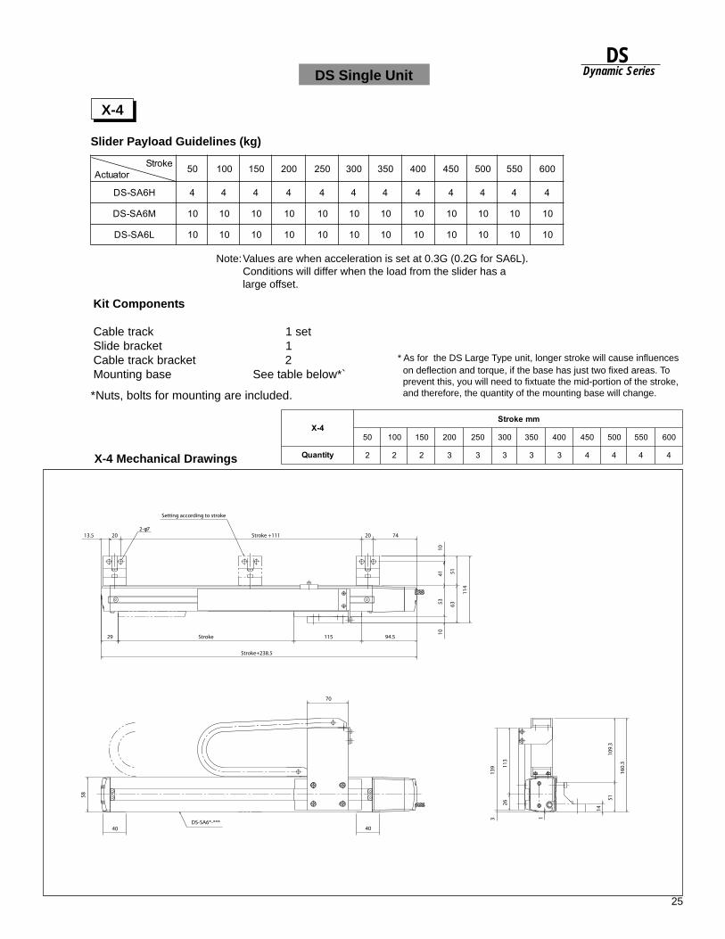
25
DSDynamic Series
Slider Payload Guidelines (kg)
Note:Values are when acceleration is set at 0.3G (0.2G for SA6L).Conditions will differ when the load from the slider has alarge offset.
X-4 Mechanical Drawings
X-4
*Nuts, bolts for mounting are included.
* As for the DS Large Type unit, longer stroke will cause influences on deflection and torque, if the base has just two fixed areas. To prevent this, you will need to fixtuate the mid-portion of the stroke, and therefore, the quantity of the mounting base will change.
DS Single Unit
Kit Components
Cable track 1 setSlide bracket 1Cable track bracket 2Mounting base See table below*`
4-XmmekortS
05 001 051 002 052 003 053 004 054 005 055 006
ytitnauQ 2 2 2 3 3 3 3 3 4 4 4 4
20 Stroke +111 20 7413.5
29 Stroke 115 94.5
70
4040
Stroke+238.5
10
5163
114
4153
10
139
58
3 1
113
26
109.
351
14
160.
3
2-φ7
DS-SA6*-***
Setting according to stroke
ekortSrotautcA 05 001 051 002 052 003 053 004 054 005 055 006
H6AS-SD 4 4 4 4 4 4 4 4 4 4 4 4
M6AS-SD 01 01 01 01 01 01 01 01 01 01 01 01
L6AS-SD 01 01 01 01 01 01 01 01 01 01 01 01

26
Y Axis Slider Payload Guidelines (kg)
XY-1 Mechanical Drawing
DS XY Unit
XY-1
X-stroke +76
74.5
Y-stroke+192.5
29 Y-stroke 70 93.5
3 120 3
94X-stroke
(75) X-stroke+197.5
3015 X-stroke+62 30 60.5
121.5
52
2-φ3H10 depth 6
X-stroke50, 150, 250, 350
4-M3 depth 7
DS-SA4 *-***
DS-SA5*-***
100
Y-s
tro
ke+
105
8
50
30
24Kit Components
Cable track 1 set Track rail 1 set
Slide base 1 Track rail 1
Mounting frame (nuts for actuator mounting plate included) 1set
* Nuts, bolts for mounting are included
Note:Values are when acceleration is
set at 0.3G. Conditions will differ when the load from the slider has a large offset.
rotautcAsixAY H4AS-SD M4AS-SD L4AS-SD
)mm(ekortSsixAY 05 001 05 001 05 001
XsixA
004~05-H5AS-SD 0.2 0.2 0.2 0.2 0.2 0.2
004~05-M5AS-SD 5.2 5.2 0.3 0.3 0.3 0.3
004~05-L5AS-SD 5.2 5.2 0.3 0.3 0.3 0.3
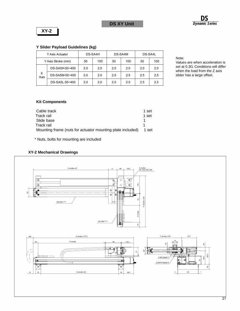
27
DSDynamic Series
Note:Values are when acceleration is
set at 0.3G. Conditions will differ when the load from the Z axis
slider has a large offset.
Y Slider Payload Guidelines (kg)
XY-2 Mechanical Drawings
DS XY Unit
XY-2
51 59.5
52
X-stroke+47
X-stroke+197.5
X-stroke
X-stroke+62
2-φ3H10 depth 6
4-M3 depth 7
X-stroke50, 150, 250, 350
DS-SA5*-***
DS-SA4*-***
Y-s
tro
ke+
106
729
Y-s
tro
ke
(40)
2924
Y-stroke+105 87.5
1203 315 30 30 60.5
51
2080
.5
3010
0.5
Kit Components
Cable track 1 set Track rail 1 set
Slide base 1 Track rail 1
Mounting frame (nuts for actuator mounting plate included) 1 set
* Nuts, bolts for mounting are included
rotautcAsixAY H4AS-SD M4AS-SD L4AS-SD
)mm(ekortSsixAY 05 001 05 001 05 001
XsixA
004~05-H5AS-SD 0.2 0.2 0.2 0.2 0.2 0.2
004~05-M5AS-SD 0.2 0.2 5.2 5.2 5.2 5.2
004~05-L5AS-SD 0.2 0.2 5.2 5.2 5.2 5.2
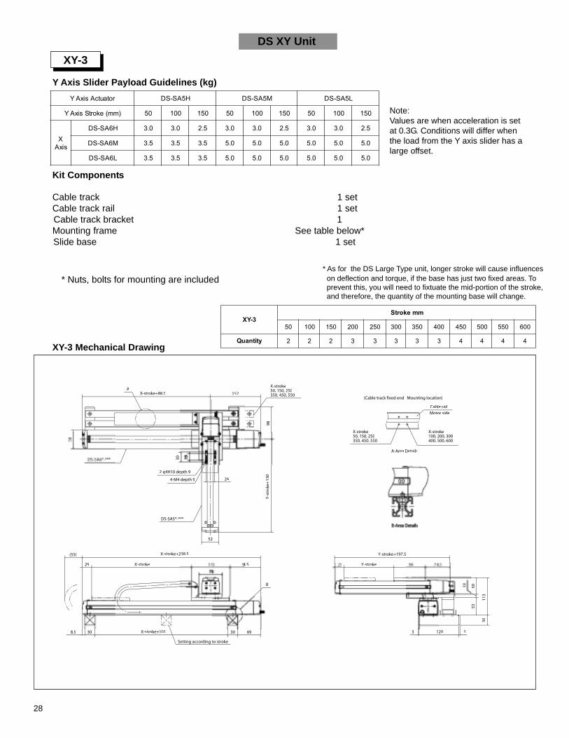
28
Note:Values are when acceleration is setat 0.3G. Conditions will differ whenthe load from the Y axis slider has alarge offset.
XY-3 Mechanical Drawing
XY-3
A152
Y-stroke+197.5
29 Y-stroke 94 74 5
120 3
(55)
29 X-stroke 115 94.5
8.5 69
B
26
98
30
X-stroke+86.5
X-stroke+238.5
X-stroke+101
2-φ4H10 depth 9
4-M4 depth 9
X-stroke50, 150, 250350, 450, 550
X-stroke50, 150, 250350, 450, 550
X-stroke100, 200, 300400, 500, 600
DS-SA5*-***
Y-s
tro
ke+
130
(Cable track fixed end Mounting location)
A-Area Details
Cable rail
Motor side
50
30
DS XY Unit
Y Axis Slider Payload Guidelines (kg)
* As for the DS Large Type unit, longer stroke will cause influences on deflection and torque, if the base has just two fixed areas. To prevent this, you will need to fixtuate the mid-portion of the stroke, and therefore, the quantity of the mounting base will change.
* Nuts, bolts for mounting are included
Kit Components
Cable track 1 setCable track rail 1 set
Cable track bracket 1Mounting frame See table below*
Slide base 1 set
rotautcAsixAY H5AS-SD M5AS-SD L5AS-SD
)mm(ekortSsixAY 05 001 051 05 001 051 05 001 051
XsixA
H6AS-SD 0.3 0.3 5.2 0.3 0.3 5.2 0.3 0.3 5.2
M6AS-SD 5.3 5.3 5.3 0.5 0.5 0.5 0.5 0.5 0.5
L6AS-SD 5.3 5.3 5.3 0.5 0.5 0.5 0.5 0.5 0.5
3-YXmmekortS
05 001 051 002 052 003 053 004 054 005 055 006
ytitnauQ 2 2 2 3 3 3 3 3 4 4 4 4
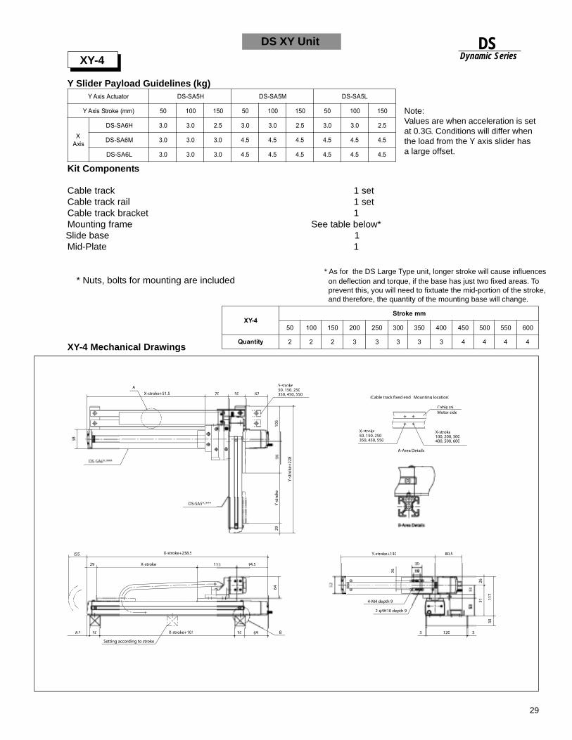
29
DSDynamic Series
Y Slider Payload Guidelines (kg)
XY-4 Mechanical Drawings
DS XY Unit
XY-4
Note:Values are when acceleration is setat 0.3G. Conditions will differ whenthe load from the Y axis slider hasa large offset.
* As for the DS Large Type unit, longer stroke will cause influences on deflection and torque, if the base has just two fixed areas. To prevent this, you will need to fixtuate the mid-portion of the stroke, and therefore, the quantity of the mounting base will change.
Kit Components
Cable track 1 setCable track rail 1 setCable track bracket 1Mounting frame See table below*
Slide base 1Mid-Plate 1
* Nuts, bolts for mounting are included
4-YXmmekortS
05 001 051 002 052 003 053 004 054 005 055 006
ytitnauQ 2 2 2 3 3 3 3 3 4 4 4 4
rotautcAsixAY H5AS-SD M5AS-SD L5AS-SD
)mm(ekortSsixAY 05 001 051 05 001 051 05 001 051
XsixA
H6AS-SD 0.3 0.3 5.2 0.3 0.3 5.2 0.3 0.3 5.2
M6AS-SD 0.3 0.3 0.3 5.4 5.4 5.4 5.4 5.4 5.4
L6AS-SD 0.3 0.3 0.3 5.4 5.4 5.4 5.4 5.4 5.4
A
70 50 67
58
105
Y-s
tro
ke64
26
91 117
30
X-stroke+51.5
X-stroke+238.5
X-stroke+101
2-φ4H10 depth 9
S-stroke50, 150, 250
DS-SA5*-***
Setting according to stroke
Y-s
tro
ke+
228
X-stroke50, 150, 250350, 450, 550
X-stroke100, 200, 300400, 500, 600
(Cable track fixed end Mounting location)
A-Area Details
Cable railMotor side
(55)
29 X-stroke 11
8.5 30 30 69 B
94.5
80.5
3 120
30
4-M4 depth 9
Y-stroke+130
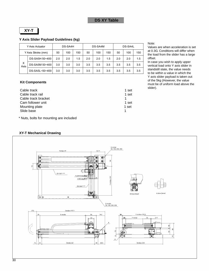
30
Y Axis Slider Payload Guidelines (kg)
XY-T Mechanical Drawing
DS XY Table
XY-T
Stroke+76 121.5
X-stroke50, 150, 250, 350
X-stroke50, 150, 250, 350
2-φ
DS-SA4*-***
DS-SA5*-***
Y-s
tro
ke+
105
99
1624
52
Stroke+197.5
Stroke+6230 30 60.515
(75)
X-stroke 94 74.5
Stroke+233
30
50
Y-stroke+192.5
Y-stroke 3.5
52
A
A-Area Detail
B
Kit Components
Cable track 1 setCable track rail 1 setCable track bracket 1Cam follower unit 1 setMounting plate 1 setSlide base 1
* Nuts, bolts for mounting are included
rotautcAsixAY H4AS-SD M4AS-SD L4AS-SD
)mm(ekortSsixAY 05 001 051 05 001 051 05 001 051
XsixA
004~05H5AS-SD 0.2 0.2 5.1 0.2 0.2 5.1 0.2 0.2 5.1
004~05M5AS-SD 0.3 0.3 0.3 5.3 5.3 5.3 5.3 5.3 5.3
004~05~L5AS-SD 0.3 0.3 0.3 5.3 5.3 5.3 5.3 5.3 5.3
Note:Values are when acceleration is setat 0.3G. Conditions will differ whenthe load from the slider has a largeoffset.In case you wish to apply uppervertical load onto Y axis slider instandstill state, the value needsto be within a value in which theY axis slider payload is taken outof the 5kg (However, the valuemust be of uniform load above theslider).
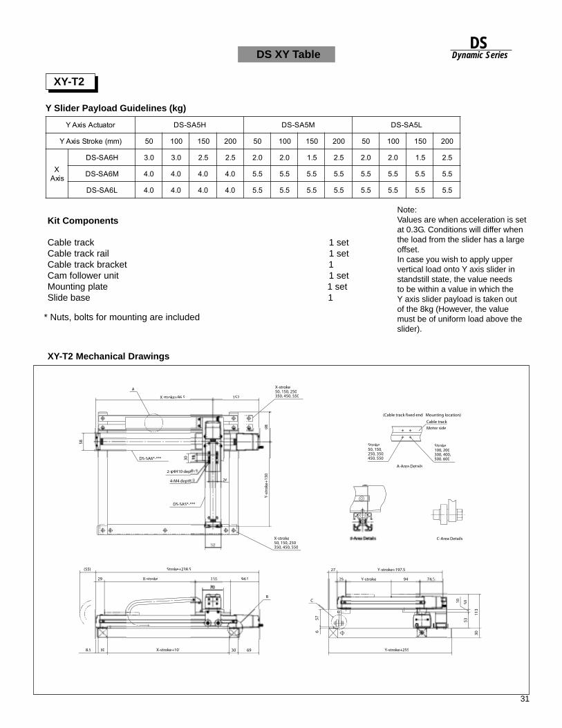
31
DSDynamic Series
XY-T2 Mechanical Drawings
DS XY Table
XY-T2
* Nuts, bolts for mounting are included
rotautcAsixAY H5AS-SD M5AS-SD L5AS-SD
)mm(ekortSsixAY 05 001 051 002 05 001 051 002 05 001 051 002
XsixA
H6AS-SD 0.3 0.3 5.2 5.2 0.2 0.2 5.1 5.2 0.2 0.2 5.1 5.2
M6AS-SD 0.4 0.4 0.4 0.4 5.5 5.5 5.5 5.5 5.5 5.5 5.5 5.5
L6AS-SD 0.4 0.4 0.4 0.4 5.5 5.5 5.5 5.5 5.5 5.5 5.5 5.5
Note:Values are when acceleration is setat 0.3G. Conditions will differ whenthe load from the slider has a largeoffset.In case you wish to apply uppervertical load onto Y axis slider instandstill state, the value needsto be within a value in which theY axis slider payload is taken outof the 8kg (However, the valuemust be of uniform load above theslider).
152
A
58
X-stroke50, 150, 250350, 450, 550
X-stroke50, 150, 250350, 450, 550
Y-s
tro
ke+
130
98
4-M4 depth
2-φ4H10 dep
DS-SA6*-***
DS-SA5*-***
Stroke+238.5(55)
X-stroke 94.5115
B
X-stroke+101308.5 6930
C
657
27
29
Y-stroke+197.5
Y-stroke 94 74 5
113
30
535010
Stroke100, 200300, 400,500, 600
Cable track
(Cable track fixed end Mounting location)
Motor side
Stroke50, 150,250, 350,450, 550
A-Area Details
C-Area Details
26
X stroke+86.5
Y-stroke+255
Y Slider Payload Guidelines (kg)
Kit Components
Cable track 1 setCable track rail 1 setCable track bracket 1Cam follower unit 1 setMounting plate 1 setSlide base 1

32
Using the DS Assembly Unit:
The DS Series was originally designed forsingle axis use but depending on theapplication, it is possible to construct a2-axis system for use. Please make noteof the following when using an assembled unit.
• Because there is one controller peraxis, the system will use point to point controlfrom a PLC or other external device.
• When the load is offset from the slider of thelast axis, the weight of the payload that canbe carried will change.
• The cable that comes with the actuator is nota bend resistant robot cable. When wiring thecables, please make sure they are not underexcessive stress. If the cables are encased ina cable track, make sure there is amplefreedom of movement for the cables.
• We have connector cables available soplease inquire about these if necessary.
Cable Hose
Kit components
Cable hose (1m/1.3m) 1Wire 1Cable hose bracket 2Cable hose connector 2Cable hose hexagon nuts 2Allen head bolts M6x20 1Hexagon nuts M6 2
Cable Hose (option)Model Type: CBH-010 (XY1, XY2, XY-T Compliance) CBH-013 (XY3, XY4, XY-T2 Compliance)This is an option for wiring treatment between XY. Mounting on themain body is done on the user side.
How to install the DS Assembly Unit:
Mounting Base (A), (C) Nut (Size M5)
Mounting method
All assembly units come with
Use a bolt to slide in and mount the nut into the T-slot of the frame.
4 spare nuts.
15
55478
45
2.3
4
2024
40
Cable hose(ø21.2Xø16.8)
ø1.6Wire
Cable hose bracket
Allen head boltM6X20
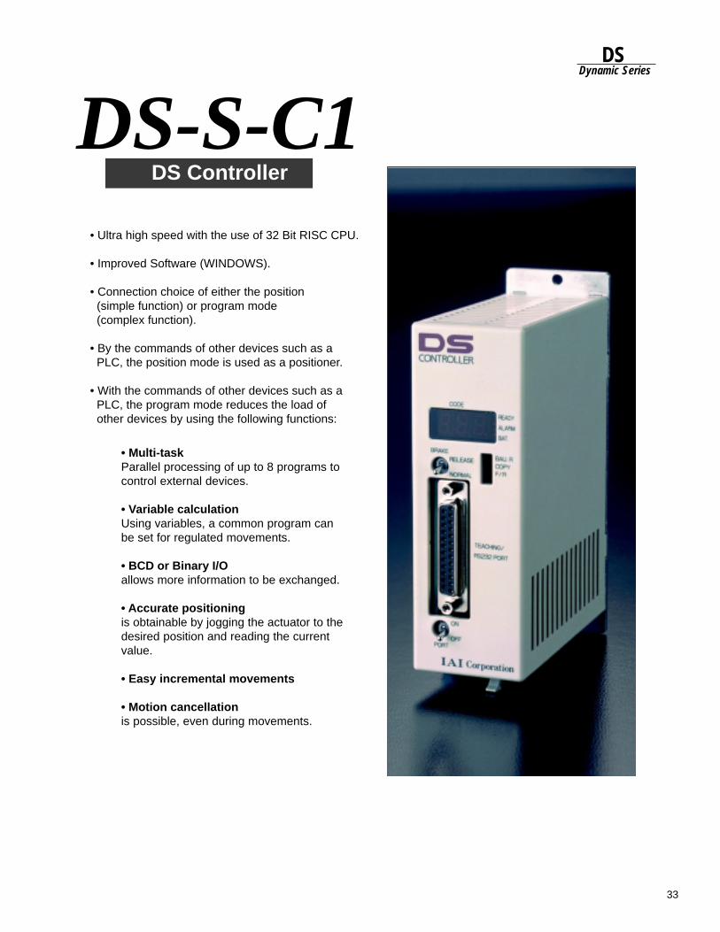
33
DSDynamic Series
DS-S-C1 DS Controller
• Multi-taskParallel processing of up to 8 programs tocontrol external devices.
• Variable calculationUsing variables, a common program canbe set for regulated movements.
• BCD or Binary I/Oallows more information to be exchanged.
• Accurate positioningis obtainable by jogging the actuator to thedesired position and reading the currentvalue.
• Easy incremental movements
• Motion cancellationis possible, even during movements.
• Ultra high speed with the use of 32 Bit RISC CPU.
• Improved Software (WINDOWS).
• Connection choice of either the position (simple function) or program mode (complex function).
• By the commands of other devices such as a PLC, the position mode is used as a positioner.
• With the commands of other devices such as a PLC, the program mode reduces the load of other devices by using the following functions:
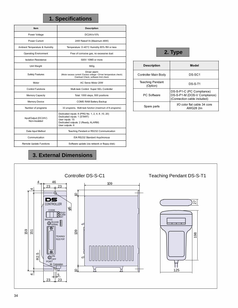
34
3. External Dimensions
2. Type
4 46 10923 23
4
1010
139
415
1
159
R2.
5
523 23
φ5
CONTROLLER
CODEREADYALARMBAT
BRAKERELEASENORMAL
TEAING/RS232 PORT
ONOFF
PORTIAI Corporation
125
2719
8
Controller DS-S-C1 Teaching Pendant DS-S-T1
1. Specifications
noitpircseD ledoM
ydoBniaMrellortnoC 1CS-SD
tnadnePgnihcaeT)noitpO( 1T-S-SD
erawtfoSCP)ecnailpmoCCP(C-1P-S-SD
)ecnailpmoCV-SOD(M-1P-S-SD)dedulcnielbacnoitcennoC(
straperapS eroc43elbactalfrolocO/Im282GWA
metI noitpircseD
egatloVrewoP %01±V42CD
tnerruCrewoP )W84mumixaM(A1/detaRW42
ytidimuH&erutarepmeTtneibmA sselroHR%58ytidimuHC°04~0:erutarepmeT
tnemnorivnEgnitarepO tsudevissecxeon,sagevisorrocfoeerF
ecnatsiseRnoitalosI eromroM01V005
thgieWtinU g065
serutaeFytefaSmralarevirD
)kcehcerutarepmetrevirD•egatlovssecxE:tnerrucssecxerotoM(kcehctimilerawtfos,kcehCdaolrevO
rotoM W02rotoMovreSCA
snoitcnuFlortnoC rellortnoCLESrepuSlortnoCksat-itluM
yticapaCyromeM snoitisop005,spets0001:latoT
eciveDyromeM pukcaByrettaBMARSMOC
smargorpforebmuN )smargorp8fomumixam(noitcnufksat-itluM,smargorp23
)V42CD(tuptuO/tupnIdetalusni-noN
)02,01,8,4,2,1.oNGRP(8:stupnidetacideD)TRATS(1:stupnidetacideD
51:stupniresU)MRALA,ydaeR(2:stuptuodetacideD
6:stuptuoresU
dohteMtupnIataD noitacinummoC232SRrotnadnePgnihcaeT
noitacinummoC suonorhcysAdradnatS232SRAIE
snoitcnuFetadpUetomeR )ksidyppolfrokrowtenaiv(etadpuerawtfoS
Ω
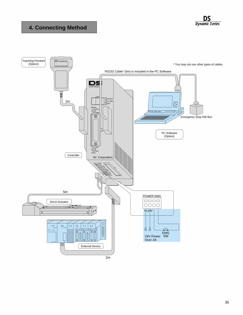
35
DSDynamic Series
4. Connecting Method
MITUBISHI MITUBISHI
POWER
INPUT OUTPUT
F1 F2 F3 F4
DS TEACHING BOXTeaching Pendant(Option)
PC Software(Option)
Emergency Stop SW Box
ALARM
READY
BAT.
CODE
RELEA
NORMA
BRAKE
PORTOFF
ON
TE
RS2
IAI Corporation
CONTROLL
MPG
BK
POWER
EMG
N
24V
POWER EMG
N 24V
24V Power Over 2A
EMGSW
o 1
Controller
Servo Actuator
RS232 Cable* (5m) is included in the PC Software
5m
2m
2m
* You may not use other types of cables.
External Device
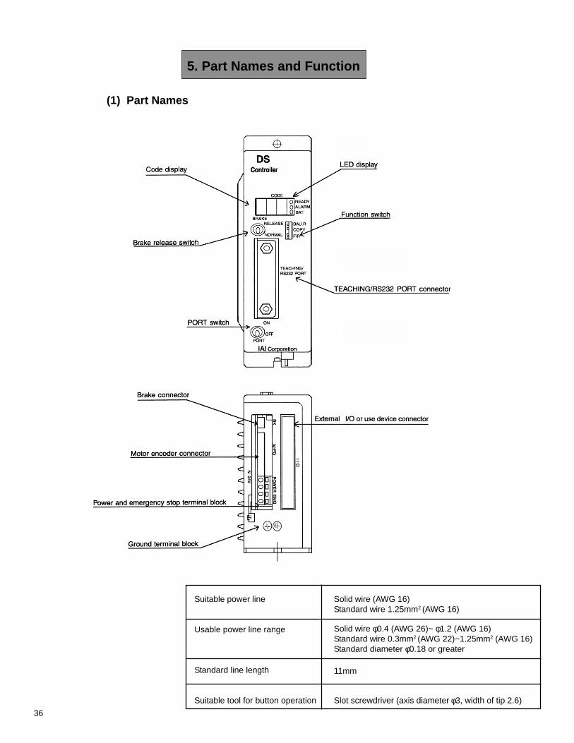
36
(1) Part Names
5. Part Names and Function
Solid wire φ0.4 (AWG 26)~ φ1.2 (AWG 16)Standard wire 0.3mm2 (AWG 22)~1.25mm2 (AWG 16)Standard diameter φ0.18 or greater
Suitable power line
Usable power line range
Standard line length
Suitable tool for button operation
Solid wire (AWG 16)Standard wire 1.25mm2 (AWG 16)
11mm
Slot screwdriver (axis diameter φ3, width of tip 2.6)
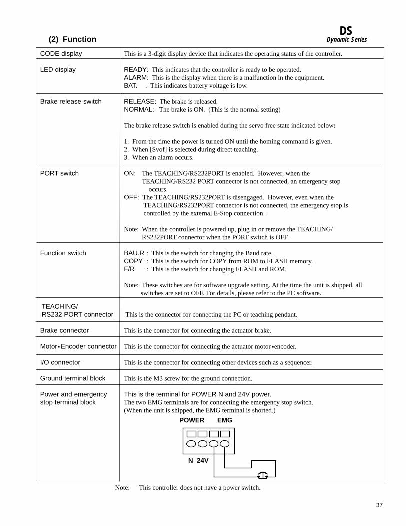
37
DSDynamic Series
Brake connector This is the connector for connecting the actuator brake.
Motor Encoder connector This is the connector for connecting the actuator motor encoder.
I/O connector This is the connector for connecting other devices such as a sequencer.
Ground terminal block This is the M3 screw for the ground connection.
Power and emergency This is the terminal for POWER N and 24V power.stop terminal block The two EMG terminals are for connecting the emergency stop switch.
(When the unit is shipped, the EMG terminal is shorted.)
POWER EMG
N 24V
CODE display This is a 3-digit display device that indicates the operating status of the controller.
LED display READY: This indicates that the controller is ready to be operated.ALARM: This is the display when there is a malfunction in the equipment.BAT. : This indicates battery voltage is low.
Brake release switch RELEASE: The brake is released.NORMAL: The brake is ON. (This is the normal setting)
The brake release switch is enabled during the servo free state indicated below:
1. From the time the power is turned ON until the homing command is given.2. When [Svof] is selected during direct teaching.3. When an alarm occurs.
PORT switch ON: The TEACHING/RS232PORT is enabled. However, when theTEACHING/RS232 PORT connector is not connected, an emergency stop occurs.
OFF: The TEACHING/RS232PORT is disengaged. However, even when the TEACHING/RS232PORT connector is not connected, the emergency stop is controlled by the external E-Stop connection.
Note: When the controller is powered up, plug in or remove the TEACHING/RS232PORT connector when the PORT switch is OFF.
Function switch BAU.R : This is the switch for changing the Baud rate.COPY : This is the switch for COPY from ROM to FLASH memory.F/R : This is the switch for changing FLASH and ROM.
Note: These switches are for software upgrade setting. At the time the unit is shipped, all switches are set to OFF. For details, please refer to the PC software.
Note: This controller does not have a power switch.
(2) Function
)))) )
TEACHING/RS232 PORT connector This is the connector for connecting the PC or teaching pendant.
. .
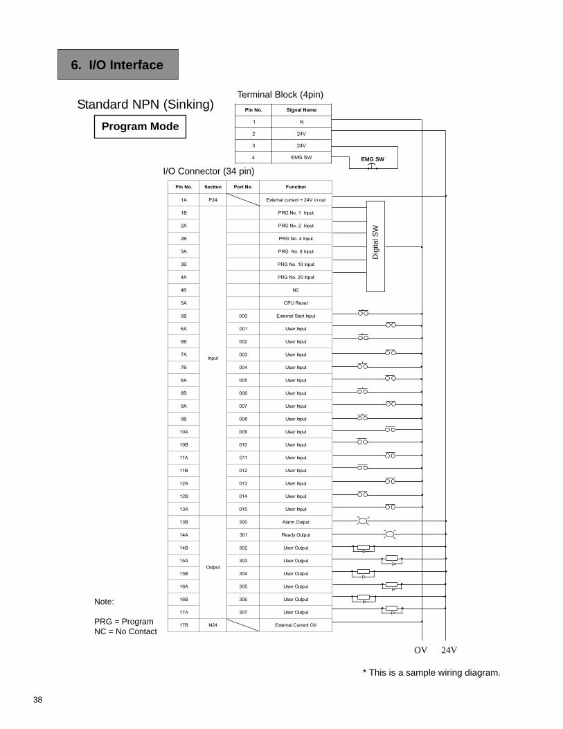
38
.oNniP noitceS .oNtroP noitcnuF
A1 42P tuoniV42+tnerruclanretxE
B1
tupnI
tupnI1.oNGRP
A2 tupnI2.oNGRP
B2 tupnI4.oNGRP
A3 tupnI8.oNGRP
B3 tupnI01.oNGRP
A4 tupnI02.oNGRP
B4 CN
A5 teseRUPC
B5 000 tupnItratSlanretxE
A6 100 tupnIresU
B6 200 tupnIresU
A7 300 tupnIresU
B7 400 tupnIresU
A8 500 tupnIresU
B8 600 tupnIresU
A9 700 tupnIresU
B9 800 tupnIresU
A01 900 tupnIresU
B01 010 tupnIresU
A11 110 tupnIresU
B11 210 tupnIresU
A21 310 tupnIresU
B21 410 tupnIresU
A31 510 tupnIresU
B31
tuptuO
003 tuptuOmralA
A41 103 tuptuOydaeR
B41 203 tuptuOresU
A51 303 tuptuOresU
B51 403 tuptuOresU
A61 503 tuptuOresU
B61 603 tuptuOresU
A71 703 tuptuOresU
B71 42N VOtnerruClanretxE
6. I/O Interface
•
•
• •
Dig
ital S
W
•
•
•
•
EMG SW)
•
•
•
•
•
•
•
•
•
•
•
• •
••
•
•
•
•
••
• •
I/O Connector (34 pin)
OV 24V
Terminal Block (4pin)
Program Mode
Note:
PRG = ProgramNC = No Contact
* This is a sample wiring diagram.
•
•
•
•
•
•
•
•
•
.oNniP emaNlangiS
1 N
2 V42
3 V42
4 WSGME
Standard NPN (Sinking)
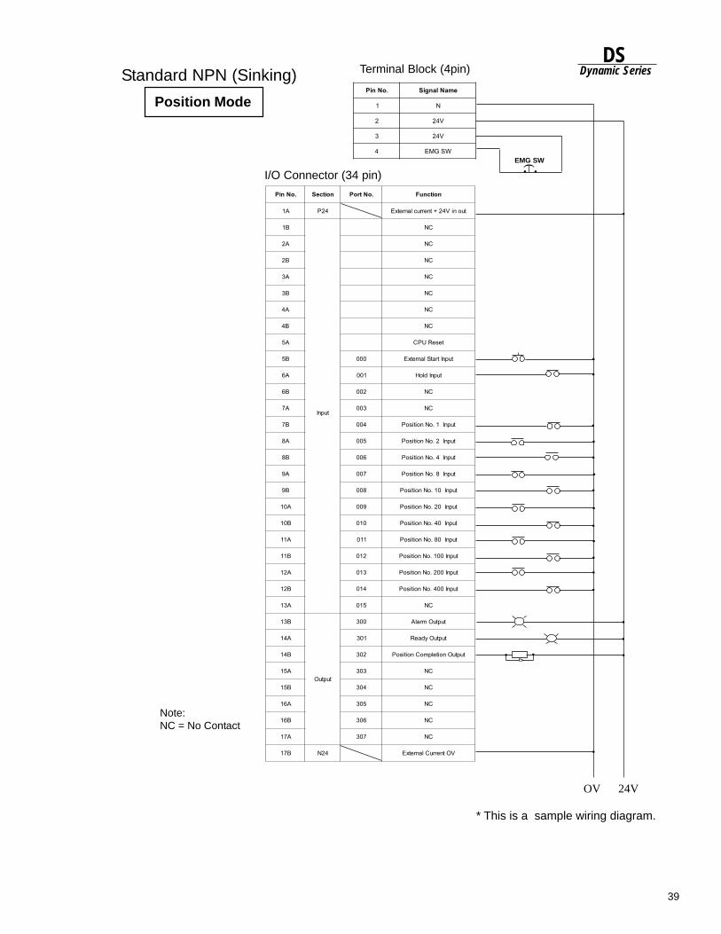
39
DSDynamic Series
.oNniP noitceS .oNtroP noitcnuF
A1 42P tuoniV42+tnerruclanretxE
B1
tupnI
CN
A2 CN
B2 CN
A3 CN
B3 CN
A4 CN
B4 CN
A5 teseRUPC
B5 000 tupnItratSlanretxE
A6 100 tupnIdloH
B6 200 CN
A7 300 CN
B7 400 tupnI1.oNnoitisoP
A8 500 tupnI2.oNnoitisoP
B8 600 tupnI4.oNnoitisoP
A9 700 tupnI8.oNnoitisoP
B9 800 tupnI01.oNnoitisoP
A01 900 tupnI02.oNnoitisoP
B01 010 tupnI04.oNnoitisoP
A11 110 tupnI08.oNnoitisoP
B11 210 tupnI001.oNnoitisoP
A21 310 tupnI002.oNnoitisoP
B21 410 tupnI004.oNnoitisoP
A31 510 CN
B31
tuptuO
003 tuptuOmralA
A41 103 tuptuOydaeR
B41 203 tuptuOnoitelpmoCnoitisoP
A51 303 CN
B51 403 CN
A61 503 CN
B61 603 CN
A71 703 CN
B71 42N VOtnerruClanretxE
• •
•
•
)
•
•
•
•
•
•
• •
I/O Connector (34 pin)
OV 24V
Terminal Block (4pin)
Position Mode
Note:NC = No Contact
•
•
* This is a sample wiring diagram.
EMG SW
•
•
•
•
•
•
•
•
.oNniP emaNlangiS
1 N
2 V42
3 V42
4 WSGME
Standard NPN (Sinking)
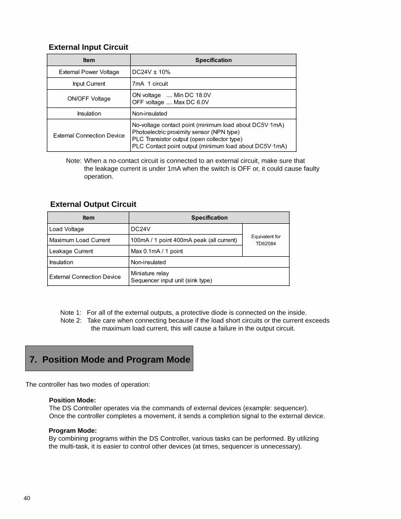
40
7. Position Mode and Program Mode
External Output Circuit
External Input Circuit
Note 1: For all of the external outputs, a protective diode is connected on the inside. Note 2: Take care when connecting because if the load short circuits or the current exceeds
the maximum load current, this will cause a failure in the output circuit.
The controller has two modes of operation:
Position Mode:The DS Controller operates via the commands of external devices (example: sequencer).Once the controller completes a movement, it sends a completion signal to the external device.
Program Mode:By combining programs within the DS Controller, various tasks can be performed. By utilizingthe multi-task, it is easier to control other devices (at times, sequencer is unnecessary).
Note: When a no-contact circuit is connected to an external circuit, make sure thatthe leakage current is under 1mA when the switch is OFF or, it could cause faultyoperation.
metI noitacificepS
egatloVrewoPlanretxE %01±V42CD
tnerruCtupnI tiucric1Am7
egatloVFFO/NO V0.81CDniM....egatlovNOV0.6CDxaM....egatlovFFO
noitalusnI detalusni-noN
eciveDnoitcennoClanretxE
)Am1·V5CDtuobadaolmuminim(tnioptcatnocegatlov-oN)epytNPN(rosnesytimixorp·cirtceleotohP)epytrotcellocnepo(tuptuorotsisnarTCLP
)Am1·V5CDtuobadaolmuminim(tuptuotnioptcatnoCCLP
metI noitacificepS
egatloVdaoL V42CDroftnelaviuqE
48026DTtnerruCdaoLmumixaM )tnerruclla(kaepAm004tniop1/Am001
tnerruCegakaeL tniop1/Am1.0xaM
noitalusnI detalusni-noN
eciveDnoitcennoClanretxE yalererutainiM)epytknis(tinutupnirecneuqeS
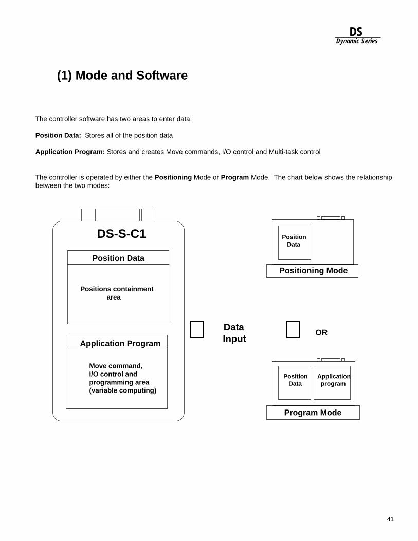
41
DSDynamic Series
(1) Mode and Software
The controller software has two areas to enter data:
Position Data: Stores all of the position data
Application Program: Stores and creates Move commands, I/O control and Multi-task control
The controller is operated by either the Positioning Mode or Program Mode. The chart below shows the relationshipbetween the two modes:
Position Data
DS-S-C1
Positions containment area
Move command,I/O control andprogramming area(variable computing)
Application Program⇐
Program Mode
Position Data
Position Data
Application program
Positioning Mode
OR Data
Input ⇐
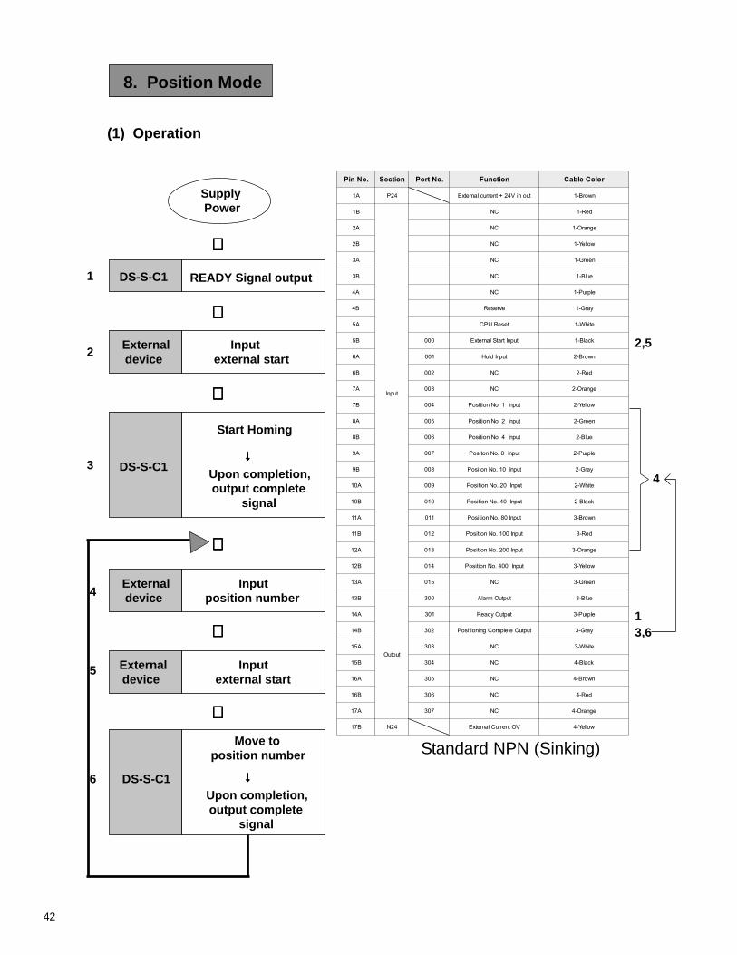
42
.oNniP noitceS .oNtroP noitcnuF roloCelbaC
A1 42P tuoniV42+tnerruclanretxE nworB-1
B1
tupnI
CN deR-1
A2 CN egnarO-1
B2 CN wolleY-1
A3 CN neerG-1
B3 CN eulB-1
A4 CN elpruP-1
B4 evreseR yarG-1
A5 teseRUPC etihW-1
B5 000 tupnItratSlanretxE kcalB-1
A6 100 tupnIdloH nworB-2
B6 200 CN deR-2
A7 300 CN egnarO-2
B7 400 tupnI1.oNnoitisoP wolleY-2
A8 500 tupnI2.oNnoitisoP neerG-2
B8 600 tupnI4.oNnoitisoP eulB-2
A9 700 tupnI8.oNnotisoP elpruP-2
B9 800 tupnI01.oNnotisoP yarG-2
A01 900 tupnI02.oNnoitisoP etihW-2
B01 010 tupnI04.oNnoitisoP kcalB-2
A11 110 tupnI08.oNnoitisoP nworB-3
B11 210 tupnI001.oNnoitisoP deR-3
A21 310 tupnI002.oNnoitisoP egnarO-3
B21 410 tupnI004.oNnoitisoP wolleY-3
A31 510 CN neerG-3
B31
tuptuO
003 tuptuOmralA eulB-3
A41 103 tuptuOydaeR elpruP-3
B41 203 tuptuOetelpmoCgninoitisoP yarG-3
A51 303 CN etihW-3
B51 403 CN kcalB-4
A61 503 CN nworB-4
B61 603 CN deR-4
A71 703 CN egnarO-4
B71 42N VOtnerruClanretxE wolleY-4
(1) Operation
Supply Power
DS-S-C1 READY Signal output
Input external start
External device
Start Homing
Upon completion, output complete signal
DS-S-C1
External device
Input position number
External device
Input external start
DS-S-C1
Move to position number
Upon completion, output complete signal
⇓⇓⇓⇓⇓
⇓⇓⇓⇓⇓
⇓⇓⇓⇓⇓
⇓⇓⇓⇓⇓
⇓⇓⇓⇓⇓
⇓⇓⇓⇓⇓
↓↓↓↓↓
↓↓↓↓↓
1
2
3
4
5
6
2,5
4
13,6
8. Position Mode
Standard NPN (Sinking)
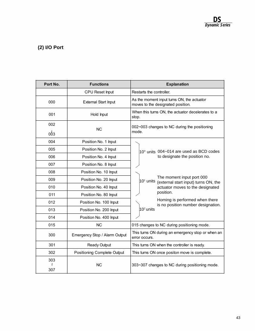
43
DSDynamic Series
.oNtroP snoitcnuF noitanalpxE
tupnIteseRUPC .rellortnocehtstratseR
000 tupnItratSlanretxE rotautcaeht,NOsnruttupnitnemomehtsA.noitisopdetangisedehtotsevom
100 tupnIdloH aotsetarelecedrotautcaeht,NOsnrutsihtnehW.pots
200
300CN gninoitisopehtgnirudCNotsegnahc300~200
.edom
400 tupnI1.oNnoitisoP
500 tupnI2.oNnoitisoP
600 tupnI4.oNnoitisoP
700 tupnI8.oNnoitisoP
800 tupnI01.oNnoitisoP
900 tupnI02.oNnoitisoP
010 tupnI04.oNnoitisoP
110 tupnI08.oNnoitisoP
210 tupnI001.oNnoitisoP
310 tupnI002.oNnoitisoP
410 tupnI004.oNnoitisoP
510 CN .edomgninoitisopgnirudCNotsegnahc510
003 tuptuOmralA/potSycnegremE nanehwropotsycnegremenagnirudNOsnrutsihT.sruccororre
103 tuptuOydaeR .ydaersirellortnocehtnehwNOsnrutsihT
203 tuptuOetelpmoCgninoitisoP .etelpmocsievomnotisopecnoNOsnrutsihT
303
703CN .edomgninoitisopgnirudCNotsegnahc703~303
(2) I/O Port~
~
10° units
101 units
102 units
004~014 are used as BCD codesto designate the position no.
The moment input port 000(external start input) turns ON, theactuator moves to the designatedposition.
Homing is performed when thereis no position number designation.
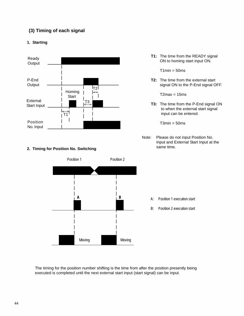
44
B
Moving Moving
A: Position 1 execution start
B: Position 2 execution start
The timing for the position number shifting is the time from after the position presently beingexecuted is completed until the next external start input (start signal) can be input.
Position 1 Position 2
T1: The time from the READY signalON to homing start input ON.
T1min = 50ms
T2: The time from the external startsignal ON to the P-End signal OFF.
T2max = 15ms
T3: The time from the P-End signal ON to when the external start signal input can be entered.
T3min = 50ms
T2
T3
T1
ReadyOutput
P-EndOutput
ExternalStart Input
PositionNo. Input
A
2. Timing for Position No. Switching
1. StartingTiming for each signal
(3) Timing of each signal
Homing Start
Note: Please do not input Position No.Input and External Start Input at thesame time.
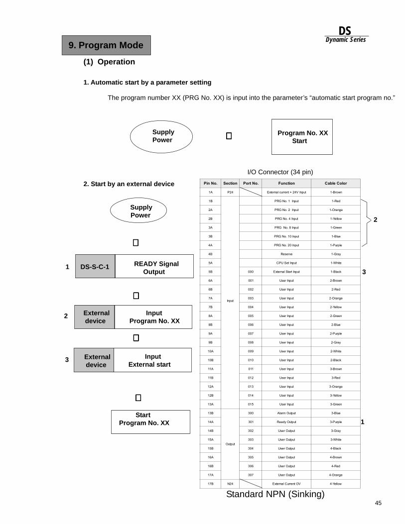
45
DSDynamic Series
.oNniP noitceS .oNtroP noitcnuF roloCelbaC
A1 42P tupnIV42+tnerruclanretxE nworB-1
B1
tupnI
tupnI1.oNGRP deR-1
A2 tupnI2.oNGRP egnarO-1
B2 tupnI4.oNGRP wolleY-1
A3 tupnI8.oNGRP neerG-1
B3 tupnI01.oNGRP eulB-1
A4 tupnI02.oNGRP elpruP-1
B4 evreseR yarG-1
A5 tupnIteSUPC etihW-1
B5 000 tupnItratSlanretxE kcalB-1
A6 100 tupnIresU nworB-2
B6 200 tupnIresU deR-2
A7 300 tupnIresU egnarO-2
B7 400 tupnIresU wolleY-2
A8 500 tupnIresU neerG-2
B8 600 tupnIresU eulB-2
A9 700 tupnIresU elpruP-2
B9 800 tupnIresU yarG-2
A01 900 tupnIresU etihW-2
B01 010 tupnIresU kcalB-2
A11 110 tupnIresU nworB-3
B11 210 tupnIresU deR-3
A21 310 tupnIresU egnarO-3
B21 410 tupnIresU wolleY-3
A31 510 tupnIresU neerG-3
B31
tuptuO
003 tuptuOmralA eulB-3
A41 103 tuptuOydaeR elpruP-3
B41 203 tuptuOresU yarG-3
A51 303 tuptuOresU etihW-3
B51 403 tuptuOresU kcalB-4
A61 503 tuptuOresU nworB-4
B61 603 tuptuOresU deR-4
A71 703 tuptuOresU egnarO-4
B71 42N VOtnerruClanretxE wolleY-4
1. Automatic start by a parameter setting
Supply Power
DS-S-C-1 READY Signal Output
External device
Input Program No. XX
⇓⇓⇓⇓⇓
⇓⇓⇓⇓⇓
1
2
2
1
3
The program number XX (PRG No. XX) is input into the parameter’s “automatic start program no.”
Program No. XX Start
2. Start by an external device
Supply Power
⇓⇓⇓⇓⇓
Start Program No. XX
I/O Connector (34 pin)
⇒⇒⇒⇒⇒
(1) Operation
9. Program Mode
3 External device
Input External start
⇓⇓⇓⇓⇓
Standard NPN (Sinking)
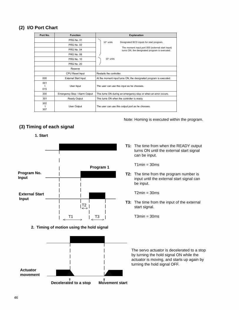
46
T1: The time from when the READY outputturns ON until the external start signalcan be input.
T1min = 30ms
T2: The time from the program number isinput until the external start signal canbe input.
T2min = 30ms
T3: The time from the input of the externalstart signal.
T3min = 30ms
T2
T1 T3
Program No.Input
External Start Input
Program 1
↑↑↑↑↑ ↑↑↑↑↑
Actuatormovement
Decelerated to a stop Movement start
The servo actuator is decelerated to a stopby turning the hold signal ON while theactuator is moving, and starts up again byturning the hold signal OFF.
Note: Homing is executed within the program.
(2) I/O Port Chart
(3) Timing of each signal
10° units Designated BCD inputs for start program.
101 units
1. Start
2. Timing of motion using the hold signal
~
~
The moment input port 000 (external start input)turns ON, the designated program is executed.
.oNtroP noitcnuF noitanalpxE
10.oNGRP
20.oNGRP
40.oNGRP
80.oNGRP
01.oNGRP
02.oNGRP
evreseR
tupnIteseRUPC .rellortnocehtstratseR
000 tupnItratSlanretxE .detucexesimargorpdetangisedeht,NOsnruttupnitnemomehttA
100
510tupnIresU .sesoohcehsatupnisihtesunacresuehT
003 tuptuOmralA/potSycnegremE .sruccororrenanehwropotsycnegremenagnirudNOsnrutsihT
103 tuptuOydaeR .ydaersirellortnocehtnehwNOsnrutsihT
203
703tuptuOresU .sesoohcehsatroptuptuosihtesunacresuehT
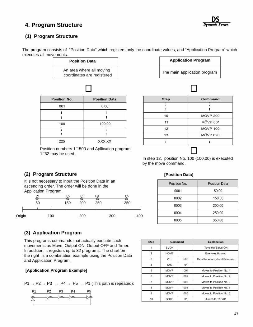
47
DSDynamic Series
petS dnammoC
01 002PVOM
11 100PVOM
21 001PVOM
31 020PVOM
4. Program Structure
(1) Program Structure
The program consists of “Position Data” which registers only the coordinate values, and “Application Program” whichexecutes all movements.
Position Data
An area where all moving coordinates are registered
Application Program
The main application program
⇓⇓⇓⇓⇓ ⇓⇓⇓⇓⇓
………… …………… …
………… …………… …
………… …………… …………… …
………… …
………… …………… …
………… …
………… …………… …
………… …
Position numbers 1∼ 500 and Apllication program1∼ 32 may be used.
In step 12, position No. 100 (100.00) is executedby the move command.
⇑⇑⇑⇑⇑
It is not necessary to input the Position Data in anascending order. The order will be done in theApplication Program.
(2) Program Structure [Position Data]
Origin 100 300 400200
350 25020015050
P1 P2 P3 P4 P5
(3) Application Program
This programs commands that actually execute suchmovements as Move, Output ON, Output OFF and Timer.In addition, it registers up to 32 programs. The chart onthe right is a combination example using the Position Dataand Application Program.
[Application Program Example]
P1 → P2 → P3 → P4 → P5 → P1 (This path is repeated):
P1 P2 P3 P5P4
.oNnoitisoP ataDnoitisoP
100 00.0
001 00.001
522 XX.XXX
.oNnoitisoP ataDnoitisoP
1000 00.05
2000 00.051
3000 00.002
4000 00.052
5000 00.053
petS dnammoC noitanalpxE
1 NOVS NOovreSehtsnruT
2 EMOH gnimoHsetucexE
3 LEV 005 ces/mm005otyticolevehtsteS
4 GAT 10
5 PVOM 100 1.oNnoitisoPotsevoM
6 PVOM 200 2.oNnoitisoPotsevoM
7 PVOM 300 3.oNnoitisoPotsevoM
8 PVOM 400 4.oNnoitisoPotsevoM
9 PVOM 500 5.oNnoitisoPotsevoM
01 OTOG 10 10GATotspmuJ
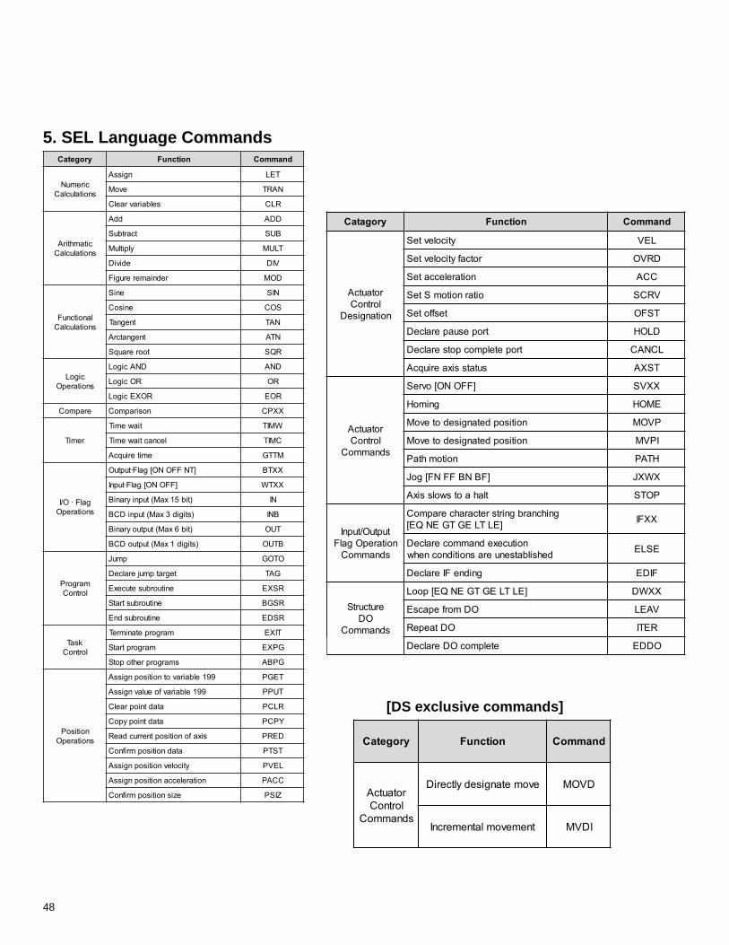
48
yrogataC noitcnuF dnammoC
rotautcAlortnoCnoitangiseD
yticolevteS LEV
rotcafyticolevteS DRVO
noitareleccateS CCA
oitarnoitomSteS VRCS
tesffoteS TSFO
tropesuaperalceD DLOH
tropetelpmocpotseralceD LCNAC
sutatssixaeriuqcA TSXA
rotautcAlortnoCsdnammoC
]FFONO[ovreS XXVS
gnimoH EMOH
noitisopdetangisedotevoM PVOM
noitisopdetangisedotevoM IPVM
noitomhtaP HTAP
]FBNBFFNF[goJ XWXJ
tlahaotswolssixA POTS
tuptuO/tupnInoitarepOgalFsdnammoC
gnihcnarbgnirtsretcarahcerapmoC]ELTLEGTGENQE[ XXFI
noitucexednammoceralceDdehsilbatsenuerasnoitidnocnehw ESLE
gnidneFIeralceD FIDE
erutcurtSOD
sdnammoC
]ELTLEGTGENQE[pooL XXWD
ODmorfepacsE VAEL
ODtaepeR RETI
etelpmocODeralceD ODDE
[DS exclusive commands]
5. SEL Language CommandsyrogetaC noitcnuF dnammoC
ciremuNsnoitaluclaC
ngissA TEL
evoM NART
selbairavraelC RLC
citamhtirAsnoitaluclaC
ddA DDA
tcartbuS BUS
ylpitluM TLUM
ediviD VID
redniamererugiF DOM
lanoitcnuFsnoitaluclaC
eniS NIS
enisoC SOC
tnegnaT NAT
tnegnatcrA NTA
toorerauqS RQS
cigoLsnoitarepO
DNAcigoL DNA
ROcigoL RO
ROXEcigoL ROE
erapmoC nosirapmoC XXPC
remiT
tiawemiT WMIT
lecnactiawemiT CMIT
emiteriuqcA MTTG
galF·O/IsnoitarepO
]TNFFONO[galF·tuptuO XXTB
]FFONO[galF·tupnI XXTW
)tib51xaM(tupniyraniB NI
)stigid3xaM(tupniDCB BNI
)tib6xaM(tuptuoyraniB TUO
)stigid1xaM(tuptuoDCB BTUO
margorPlortnoC
pmuJ OTOG
tegratpmujeralceD GAT
enituorbusetucexE RSXE
enituorbustratS RSGB
enituorbusdnE RSDE
ksaTlortnoC
margorpetanimreT TIXE
margorptratS GPXE
smargorprehtopotS GPBA
noitisoPsnoitarepO
991elbairavotnoitisopngissA TEGP
991elbairavfoeulavngissA TUPP
atadtniopraelC RLCP
atadtniopypoC YPCP
sixafonoitisoptnerrucdaeR DERP
atadnoitisopmrifnoC TSTP
yticolevnoitisopngissA LEVP
noitareleccanoitisopngissA CCAP
ezisnoitisopmrifnoC ZISP
yrogetaC noitcnuF dnammoC
rotautcAlortnoCsdnammoC
evometangisedyltceriD DVOM
tnemevomlatnemercnI IDVM
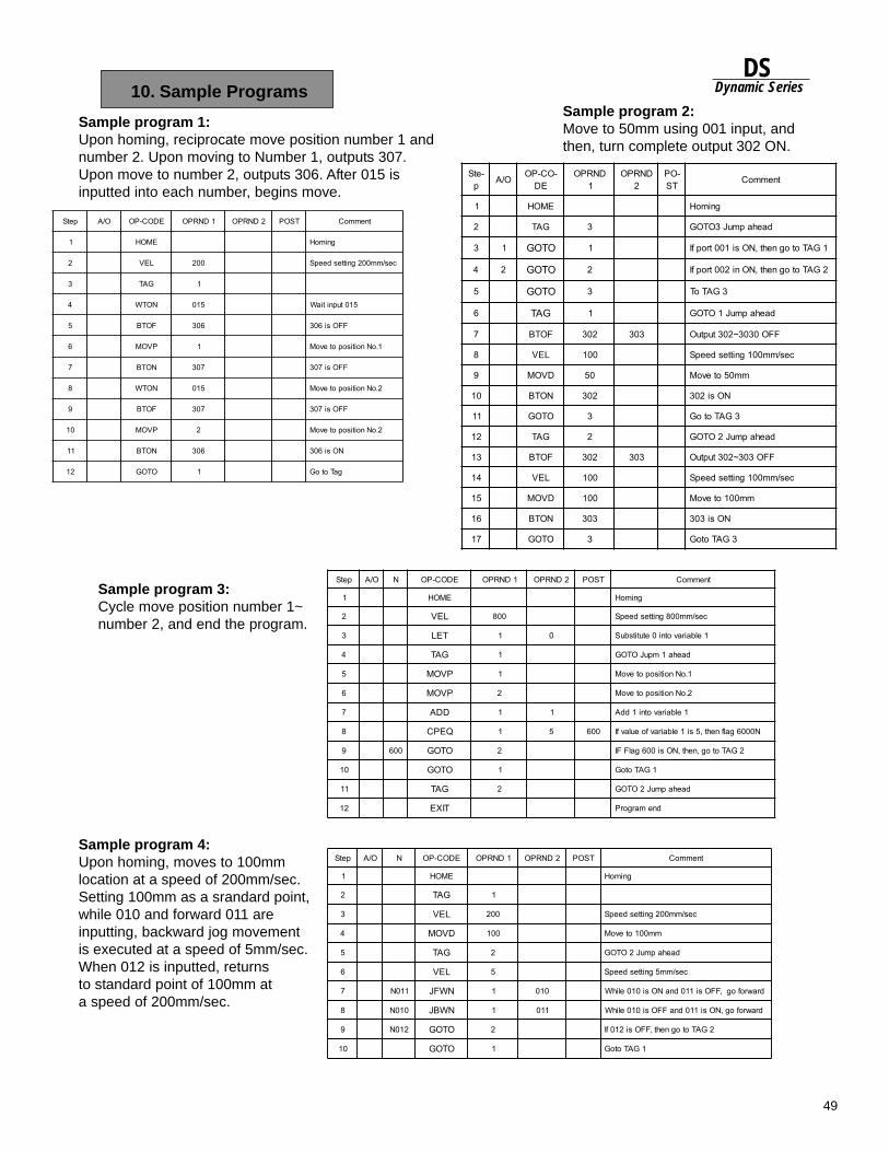
49
DSDynamic Series
Sample program 3:Cycle move position number 1~number 2, and end the program.
Sample program 4:Upon homing, moves to 100mmlocation at a speed of 200mm/sec.Setting 100mm as a srandard point,while 010 and forward 011 areinputting, backward jog movementis executed at a speed of 5mm/sec.When 012 is inputted, returnsto standard point of 100mm ata speed of 200mm/sec.
10. Sample Programs
Sample program 1:Upon homing, reciprocate move position number 1 andnumber 2. Upon moving to Number 1, outputs 307.Upon move to number 2, outputs 306. After 015 isinputted into each number, begins move.
Sample program 2:Move to 50mm using 001 input, andthen, turn complete output 302 ON.
petS O/A EDOC-PO 1DNRPO 2DNRPO TSOP tnemmoC
1 EMOH gnimoH
2 LEV 002 ces/mm002gnittesdeepS
3 GAT 1
4 NOTW 510 510tupnitiaW
5 FOTB 603 FFOsi603
6 PVOM 1 1.oNnoitisopotevoM
7 NOTB 703 FFOsi703
8 NOTW 510 2.oNnoitisopotevoM
9 FOTB 703 FFOsi703
01 PVOM 2 2.oNnoitisopotevoM
11 NOTB 603 NOsi603
21 OTOG 1 gaTotoG
-etSp O/A -OC-PO
EDDNRPO
1DNRPO
2-OPTS tnemmoC
1 EMOH gnimoH
2 GAT 3 daehapmuJ3OTOG
3 1 OTOG 1 1GATotogneht,NOsi100tropfI
4 2 OTOG 2 2GATotogneht,NOni200tropfI
5 OTOG 3 3GAToT
6 GAT 1 daehapmuJ1OTOG
7 FOTB 203 303 FFO0303~203tuptuO
8 LEV 001 ces/mm001gnittesdeepS
9 DVOM 05 mm05otevoM
01 NOTB 203 NOsi203
11 OTOG 3 3GATotoG
21 GAT 2 daehapmuJ2OTOG
31 FOTB 203 303 FFO303~203tuptuO
41 LEV 001 ces/mm001gnittesdeepS
51 DVOM 001 mm001otevoM
61 NOTB 303 NOsi303
71 OTOG 3 3GATotoG
petS O/A N EDOC-PO 1DNRPO 2DNRPO TSOP tnemmoC
1 EMOH gnimoH
2 LEV 008 ces/mm008gnittesdeepS
3 TEL 1 0 1elbairavotni0etutitsbuS
4 GAT 1 daeha1mpuJOTOG
5 PVOM 1 1.oNnoitisopotevoM
6 PVOM 2 2.oNnoitisopotevoM
7 DDA 1 1 1elbairavotni1ddA
8 QEPC 1 5 006 N0006galfneht,5si1elbairavfoeulavfI
9 006 OTOG 2 2GATotog,neht,NOsi006galFFI
01 OTOG 1 1GATotoG
11 GAT 2 daehapmuJ2OTOG
21 TIXE dnemargorP
petS O/A N EDOC-PO 1DNRPO 2DNRPO TSOP tnemmoC
1 EMOH gnimoH
2 GAT 1
3 LEV 002 ces/mm002gnittesdeepS
4 DVOM 001 mm001otevoM
5 GAT 2 daehapmuJ2OTOG
6 LEV 5 ces/mm5gnittesdeepS
7 110N NWFJ 1 010 drawrofog,FFOsi110dnaNOsi010elihW
8 010N NWBJ 1 110 drawrofog,NOsi110dnaFFOsi010elihW
9 210N OTOG 2 2GATotogneht,FFOsi210fI
01 OTOG 1 1GATotoG
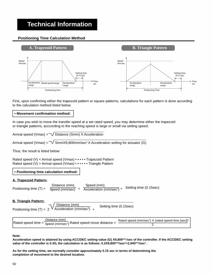
50
First, upon confirming either the trapezoid pattern or square patterns, calculations for each pattern is done accordingto the calculation method listed below.
• Movement confirmation method:
In case you wish to move the transfer speed at a set rated speed, you may determine either the trapezoidor triangle patterns, acccording to the reaching speed is large or small via setting speed.
Arrival speed (Vmax) = Distance (Smm) X Acceleration
Arrival speed (Vmax) = SmmX9,800mm/sec2 X Acceleration setting for actuator (G)
Thus, the result is listed below:
Rated speed (V) < Arrival speed (Vmax) • • • • • Trapezoid PatternRated speed (V) > Arrival speed (Vmax) • • • • • • Triangle Pattern
• Positioning time calculation method:
A. Trapezoid Pattern:
Positioning time (T) = + +
B. Triangle Pattern:
Positioning time (T) = 2 +
A. Trapezoid Pattern
B. Triangle PatternA. Trapezoid Pattern
Distance (mm) Speed (mm/sec)
Speed (mm) Acceleration (mm/sec2) Setting time (0.15sec)
Distance (mm) Acceleration (mm/sec2)
Rated speed time = Rated speed move distance = Distance (mm) Speed (mm/sec2)
Rated speed (mm/sec2) X (rated speed time [sec])2
2
Note:Acceleration speed is attained by using ACC/DEC setting value (G) X9,800mm /sec of the controller. If the ACC/DEC settingvalue of the controller is 0.3G, the calculation is as follows: 0.3X9,800mm/sec2=2,940mm/sec2 .
As for the setting time, we normally consider approximately 0.15 sec in terms of determining thecompletion of movement to the desired location.
Positioning Time Calculation Method
Technical Information
Speedmm/sec
Accelerationrange
Positioning Time
Deceleration range
Timesec
Setting time (0.15 sec)
Setting time (0.15sec)
Speedmm/sec
Acceleration. range
Rated speed range
Positioning time
Decelerationrange
Timesec
Setting time (0.15 sec)
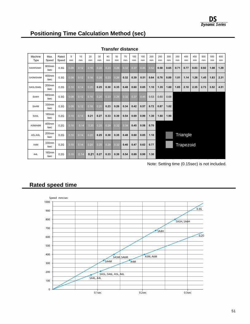
51
DSDynamic Series
enihcaMepyT
.xaMdeepS
detaRdeepS
5mm
01mm
02mm
03mm
04mm
05mm
57mm
001mm
051mm
002mm
052mm
003mm
053mm
004mm
054mm
005mm
055mm
006mm
H6AS/H5ASmm008ces/ G3.0 80.0 21.0 61.0 02.0 32.0 62.0 23.0 73.0 54.0 25.0 85.0 56.0 17.0 77.0 38.0 29.0 80.1 92.1
M6AS/M5ASmm004ces/ G3.0 80.0 21.0 61.0 02.0 32.0 62.0 23.0 93.0 15.0 46.0 67.0 98.0 10.1 41.1 62.1 54.1 38.1 13.2
L6AS/L5ASmm002ces/ G2.0 01.0 41.0 02.0 52.0 03.0 53.0 84.0 06.0 58.0 01.1 53.1 06.1 58.1 01.2 53.2 37.2 25.3 15.4
H4ASmm566ces/ G3.0 80.0 21.0 61.0 02.0 32.0 62.0 23.0 73.0 54.0 35.0 06.0 86.0
M4ASmm033ces/ G3.0 80.0 21.0 61.0 02.0 32.0 62.0 43.0 24.0 75.0 27.0 78.0 20.1
L4ASmm561ces/ G2.0 01.0 41.0 12.0 72.0 33.0 93.0 45.0 96.0 99.0 03.1 06.1 09.1
M6A/M5Amm004ces/ G2.0 01.0 41.0 02.0 52.0 92.0 23.0 93.0 54.0 85.0 07.0
L5A/L5Amm002ces/ G2.0 01.0 41.0 02.0 52.0 03.0 53.0 84.0 06.0 58.0 01.1
M4Amm033ces/ G2.0 01.0 41.0 02.0 52.0 92.0 23.0 04.0 74.0 26.0 77.0
L4Amm561ces/ G2.0 01.0 41.0 12.0 72.0 33.0 93.0 45.0 96.0 99.0 03.1
Rated speed time
Triangle
Trapezoid
Positioning Time Calculation Method (sec)
Transfer distance
Triangle
Trapezoid
Note: Setting time (0.15sec) is not included.
1000
900
800
700
600
500
400
300
200
100
00.1sec
Speed
0.2sec 0.3sec
SA4L, A4L
A4M
A5M, A6M
SA4M
SA5M, SA6M
SA4H
SA5H, SA6H
0.3G
0.2G
SA5L, SA6L, A5L, A6L
mm/sec
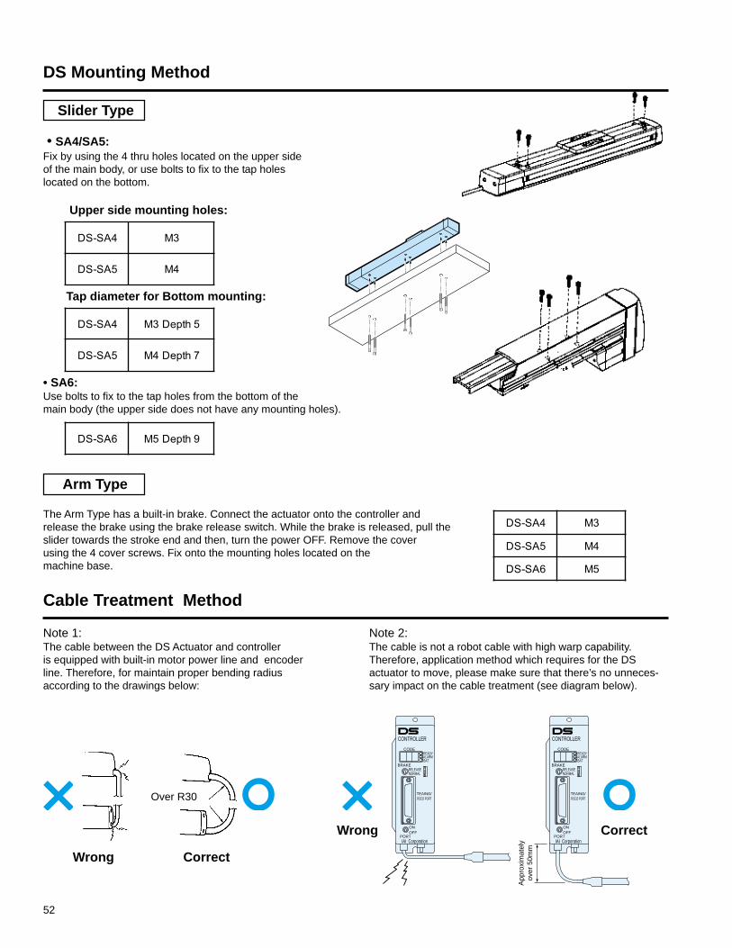
52
• SA4/SA5:Fix by using the 4 thru holes located on the upper sideof the main body, or use bolts to fix to the tap holeslocated on the bottom.
Upper side mounting holes:
Tap diameter for Bottom mounting:
• SA6:Use bolts to fix to the tap holes from the bottom of themain body (the upper side does not have any mounting holes).
Arm Type
The Arm Type has a built-in brake. Connect the actuator onto the controller andrelease the brake using the brake release switch. While the brake is released, pull theslider towards the stroke end and then, turn the power OFF. Remove the coverusing the 4 cover screws. Fix onto the mounting holes located on themachine base.
Slider Type
DS Mounting Method
Cable Treatment Method
CONTROLLER
CODEREADYALARMBAT
BRAKERELEASENORMAL
TEAING/RS232 PORT
ONOFF
PORTIAI Corporation
CONTROLLER
CODEREADYALARMBAT
BRAKERELEASENORMAL
TEAING/RS232 PORT
ONOFF
PORTIAI Corporation
App
roxi
mat
ely
over
50m
m
Note 1:The cable between the DS Actuator and controlleris equipped with built-in motor power line and encoderline. Therefore, for maintain proper bending radiusaccording to the drawings below:
Note 2:The cable is not a robot cable with high warp capability.Therefore, application method which requires for the DSactuator to move, please make sure that there’s no unneces-sary impact on the cable treatment (see diagram below).
CorrectWrong
CorrectWrong
Over R30
4AS-SD 3M
5AS-SD 4M
4AS-SD 5htpeD3M
5AS-SD 7htpeD4M
6AS-SD 9htpeD5M
4AS-SD 3M
5AS-SD 4M
6AS-SD 5M

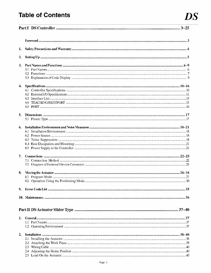
Page 1
Page 2

Page 3
Page 4
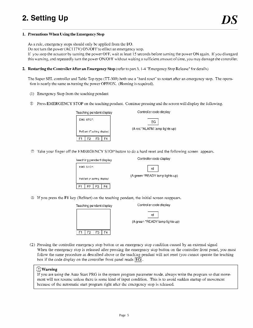
Page 5
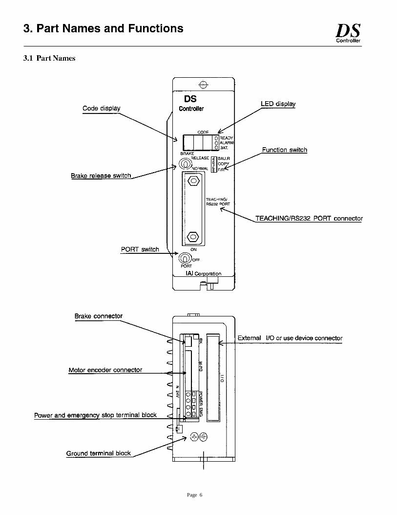
Page 6
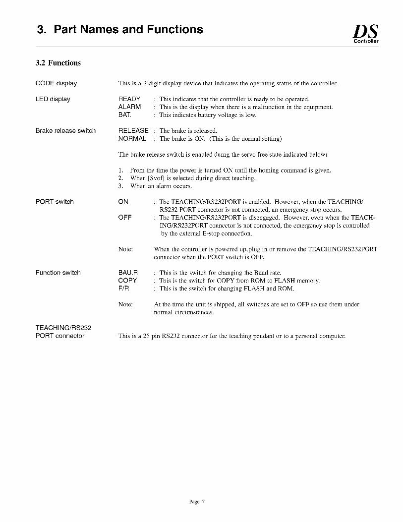
Page 7
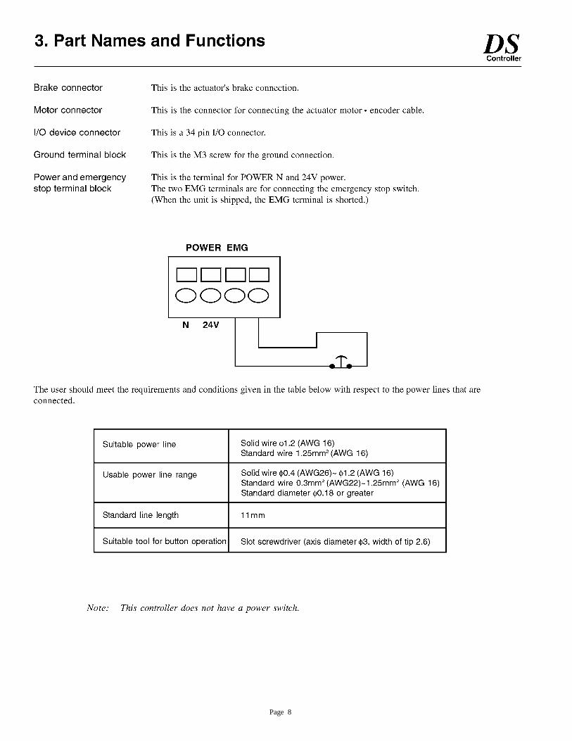
Page 8
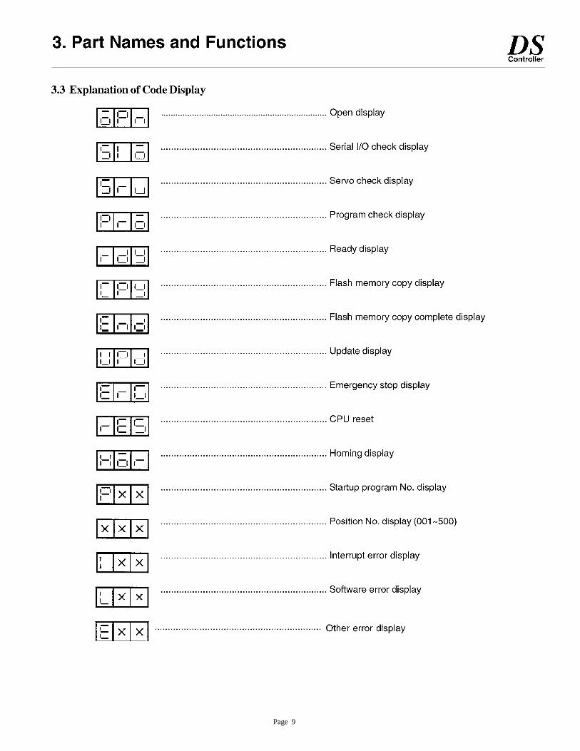
Page 9
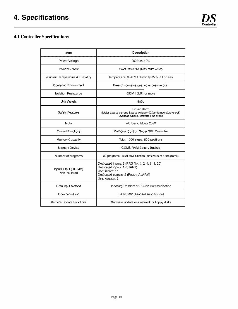
Page 10
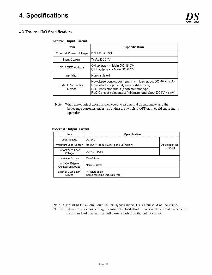
Page 11
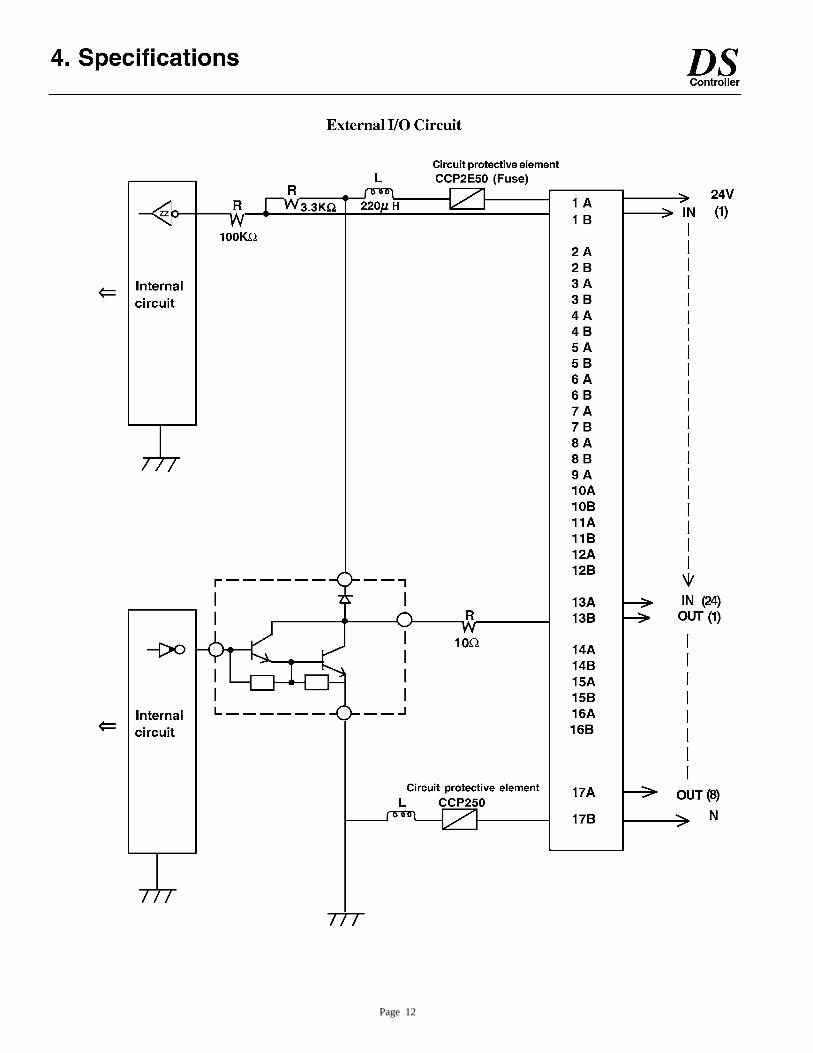
Page 12
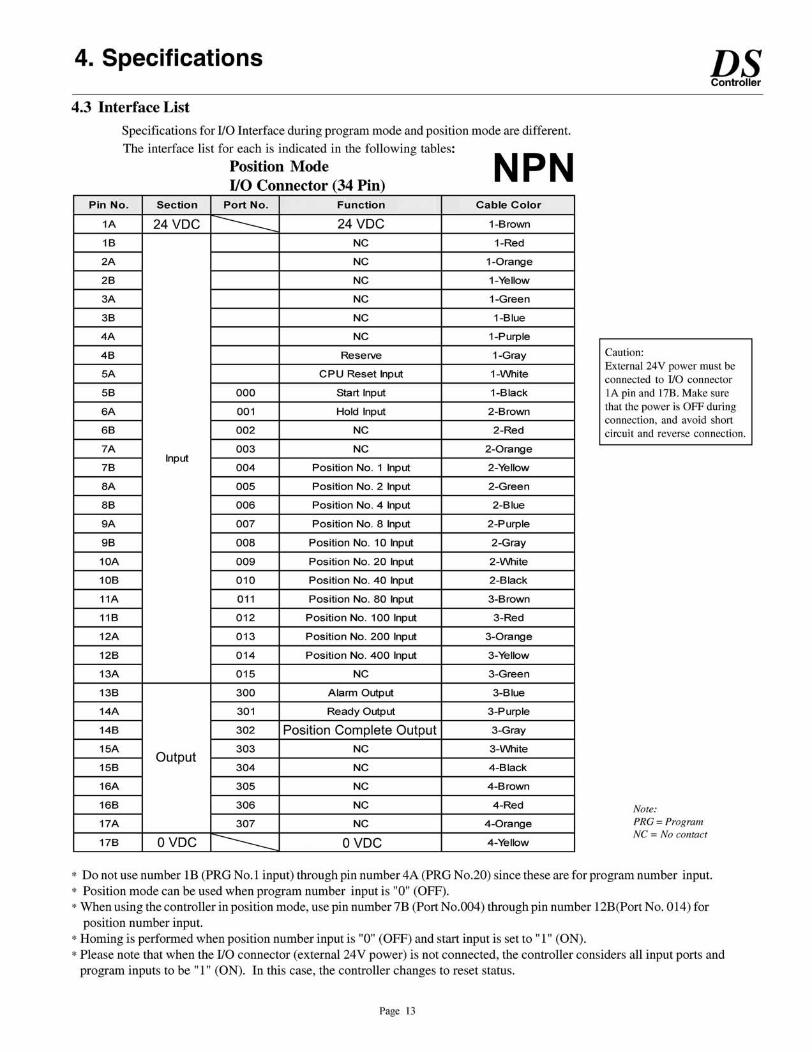
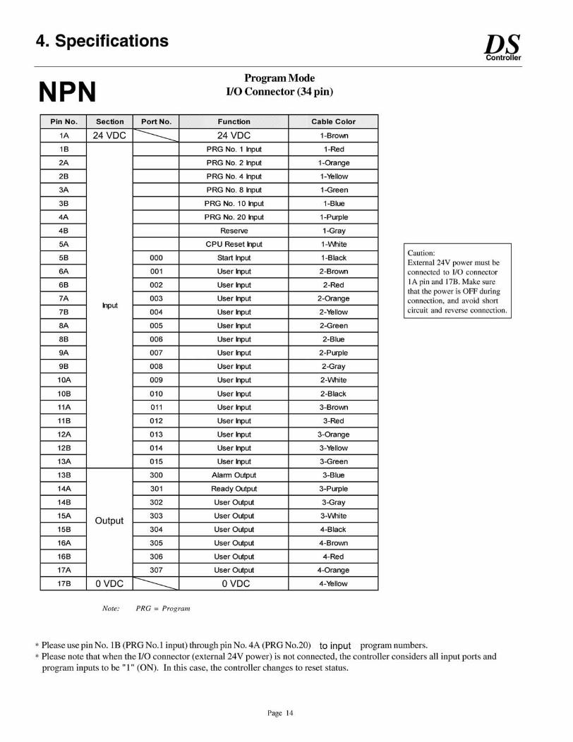
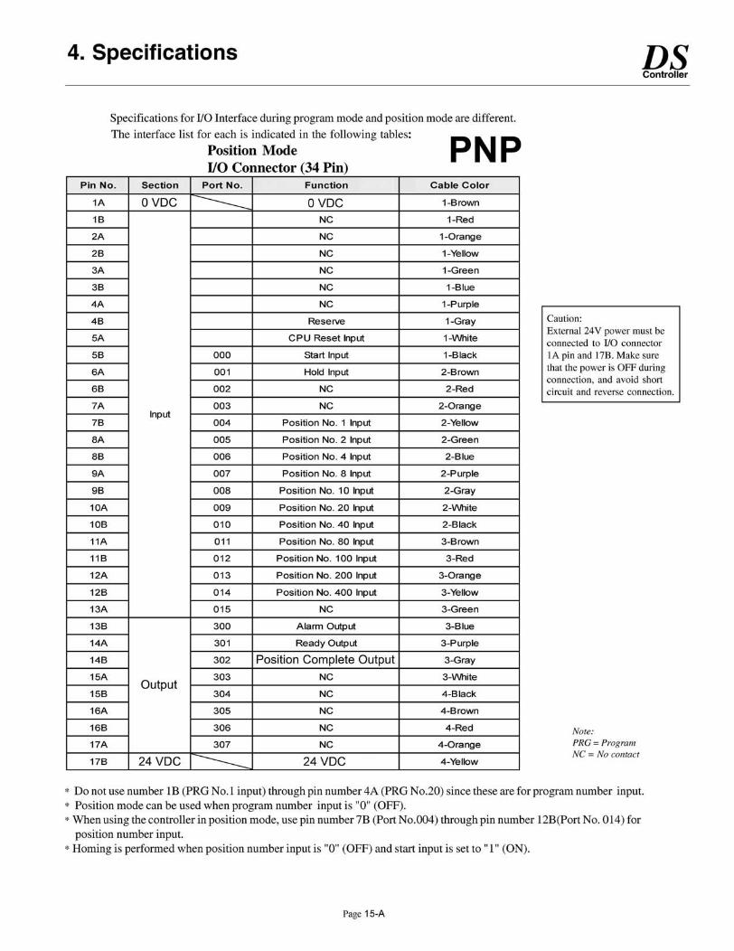
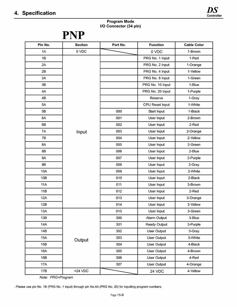
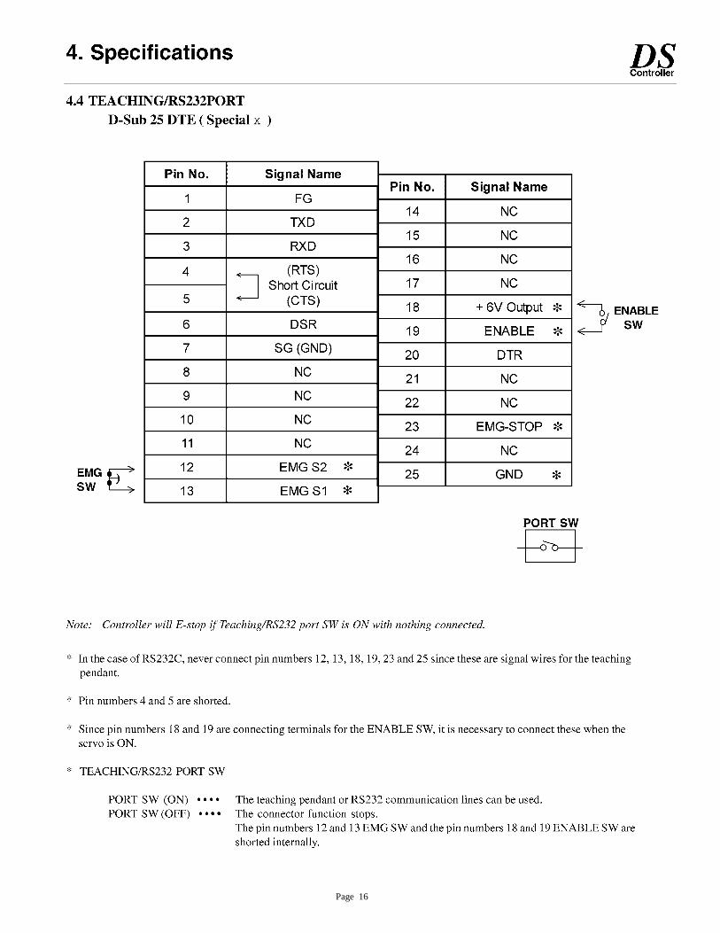
Page 16
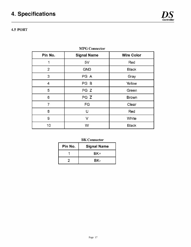
Page 17
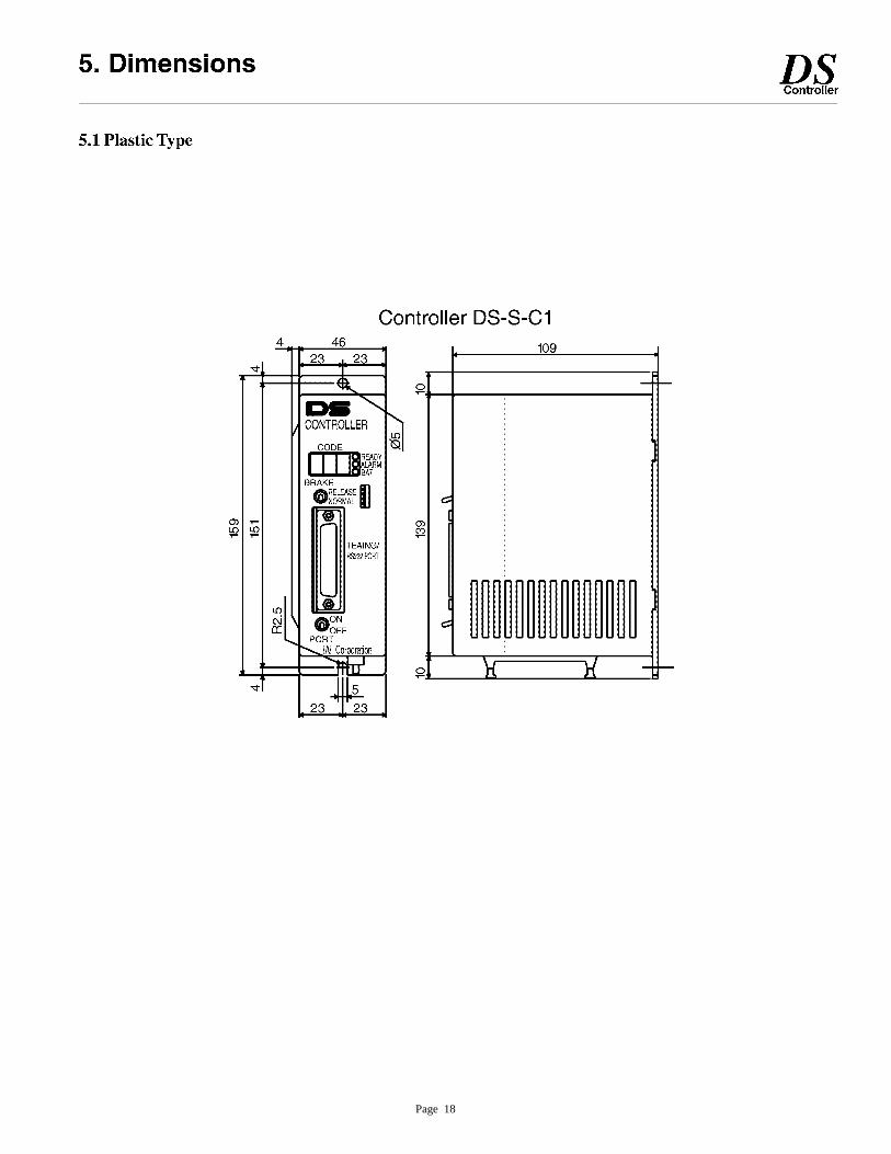
Page 18
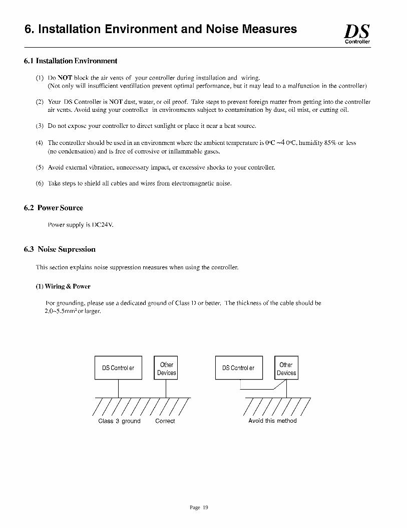
Page 19
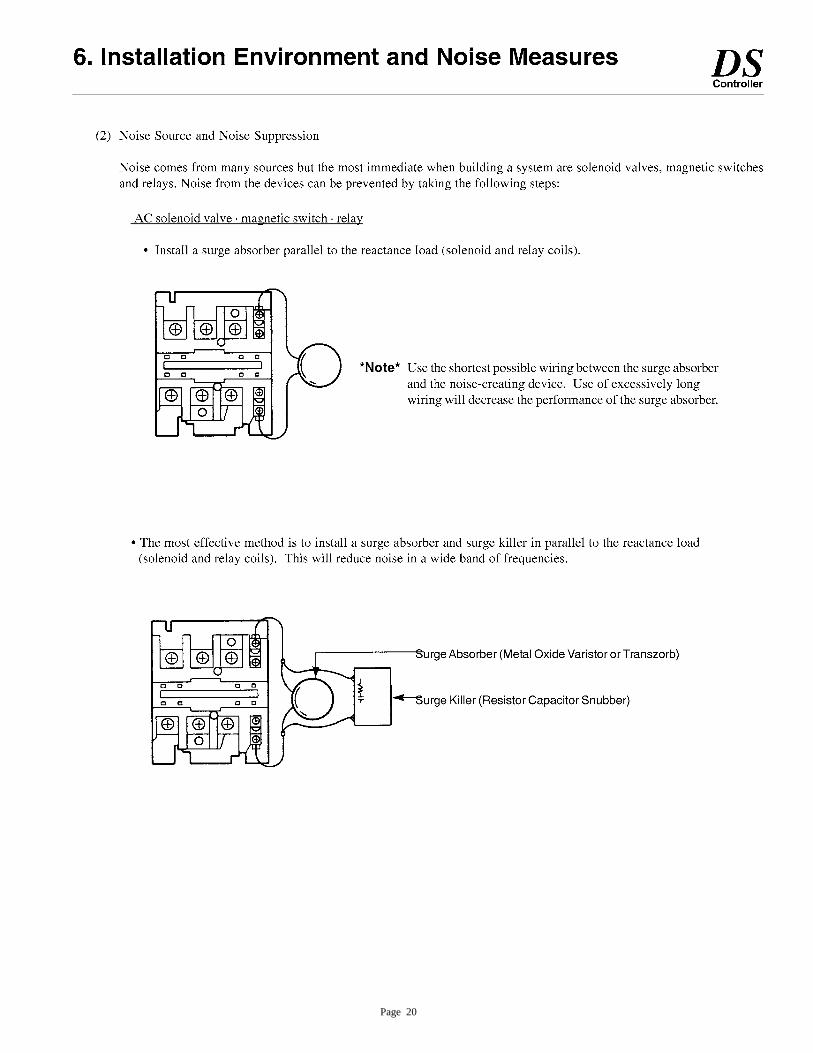
Page 20
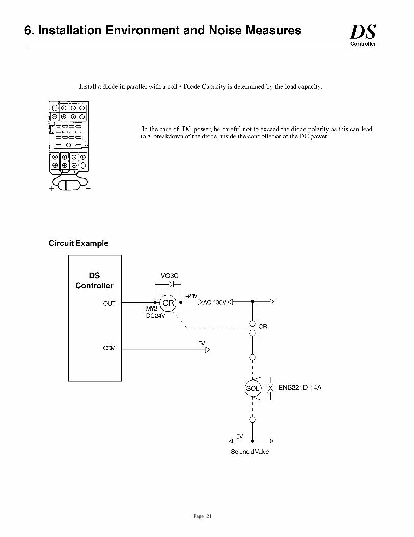
Page 21
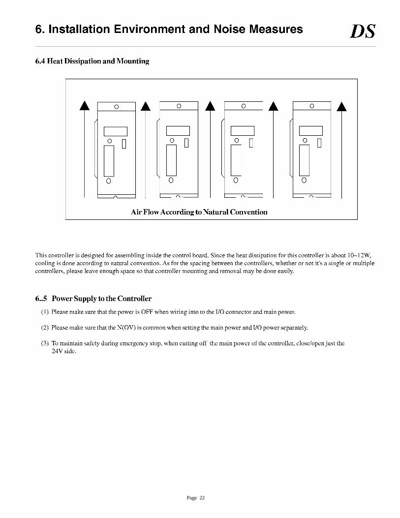
Page 22
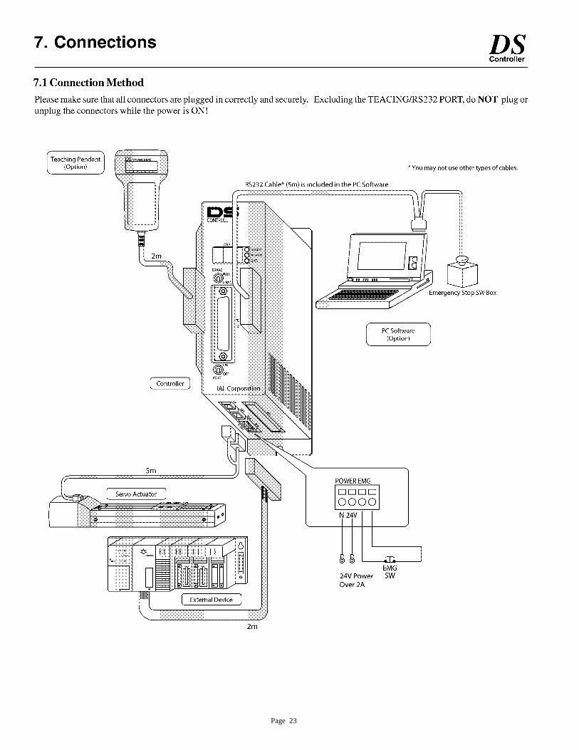
Page 23
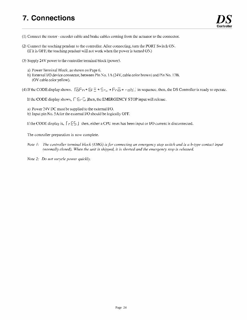
Page 24
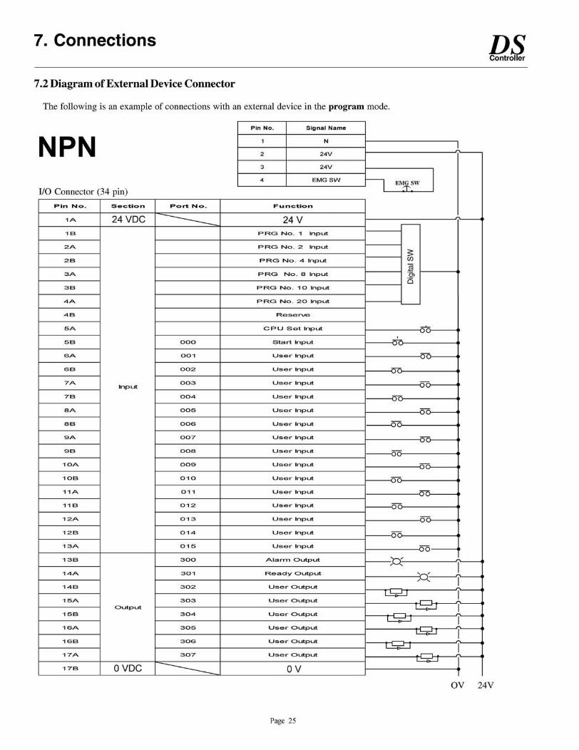
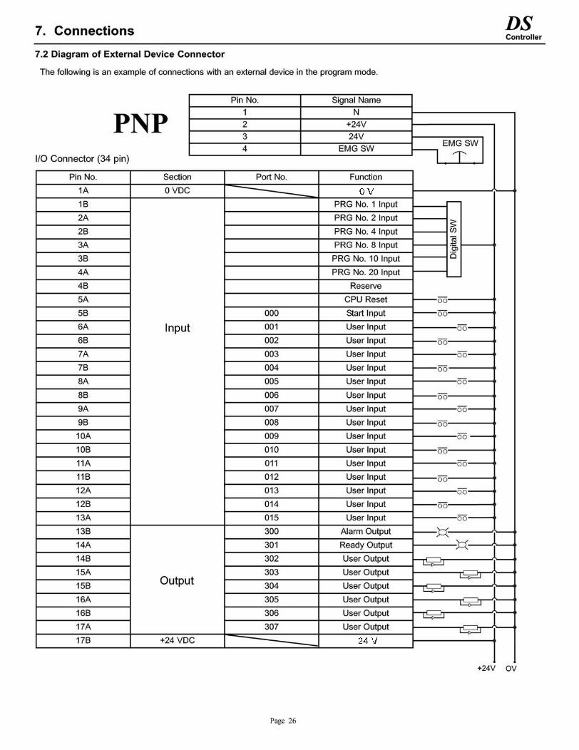
24 V
0 V
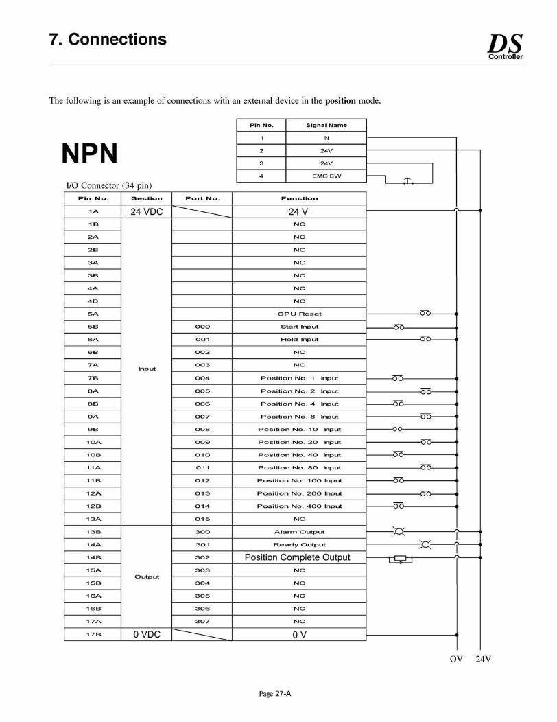
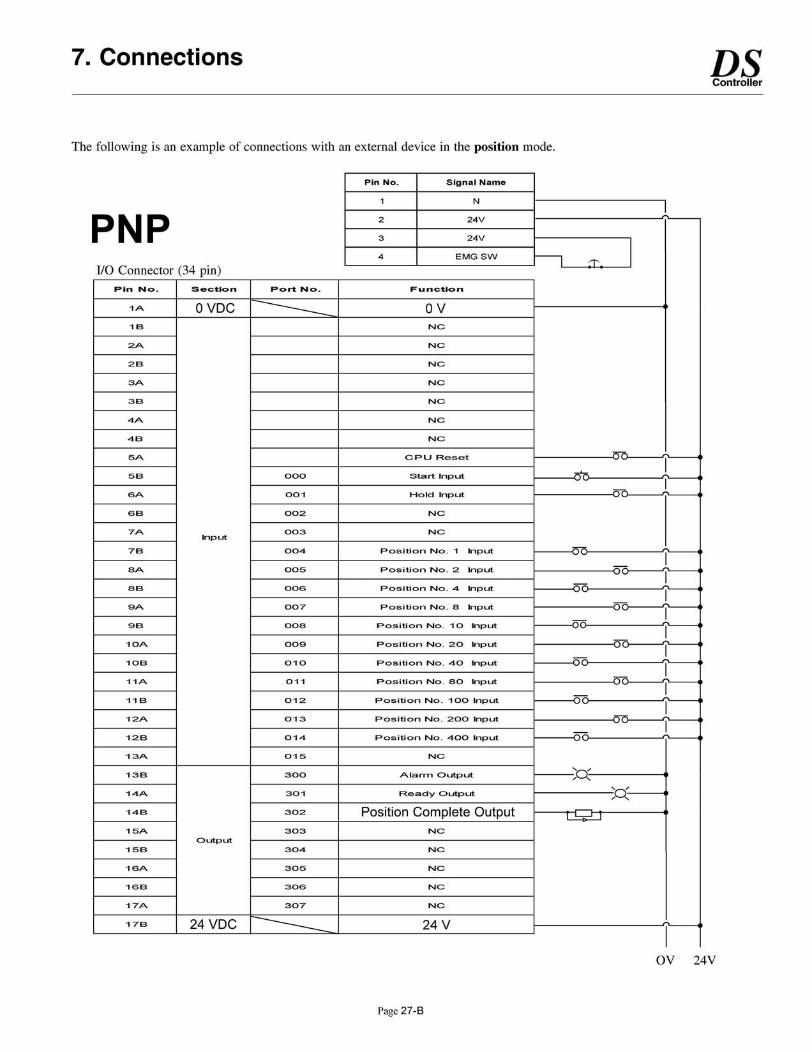
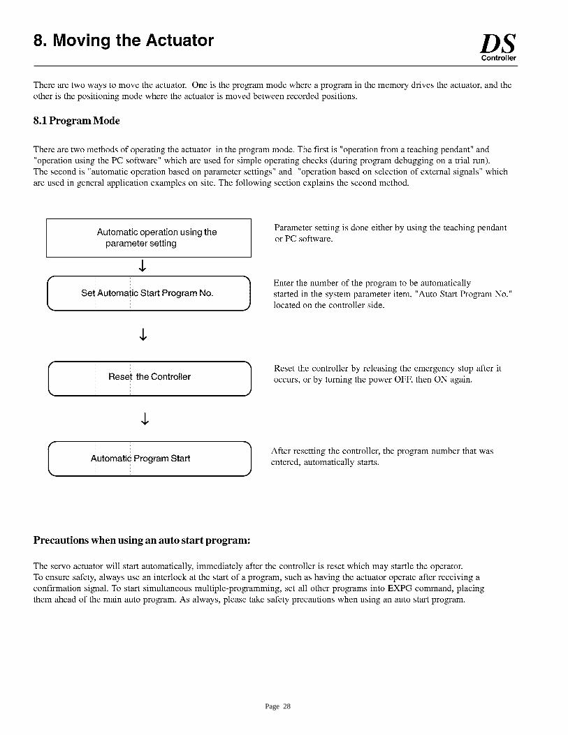
Page 28
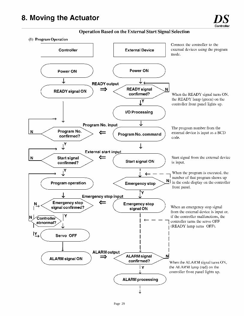
Page 29
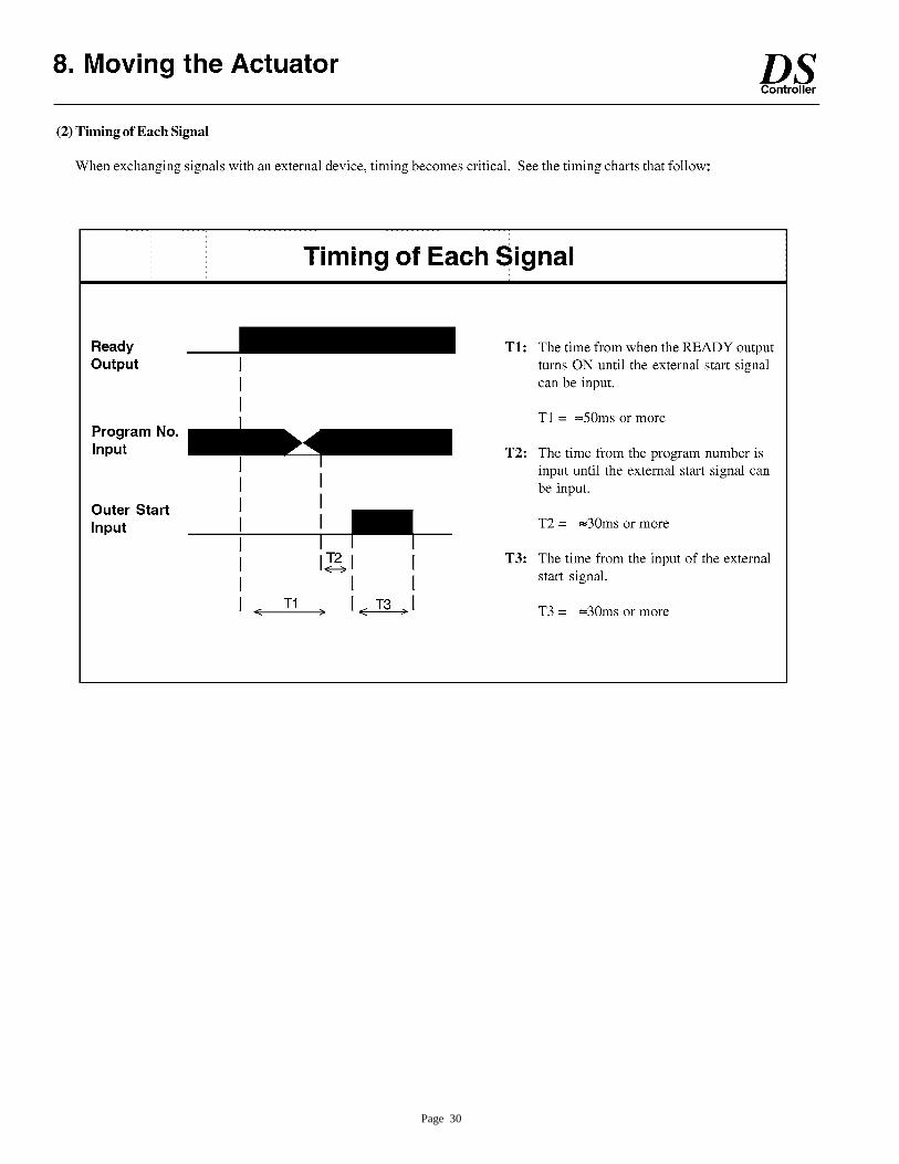
Page 30
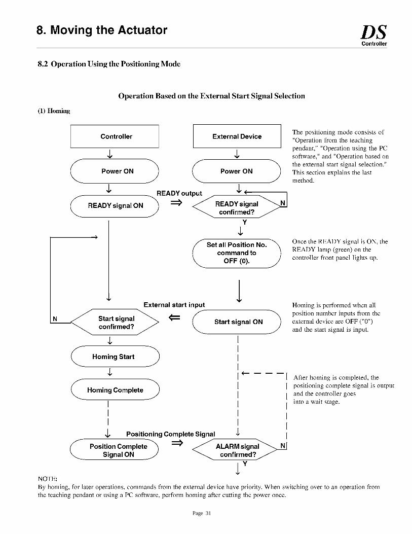
Page 31
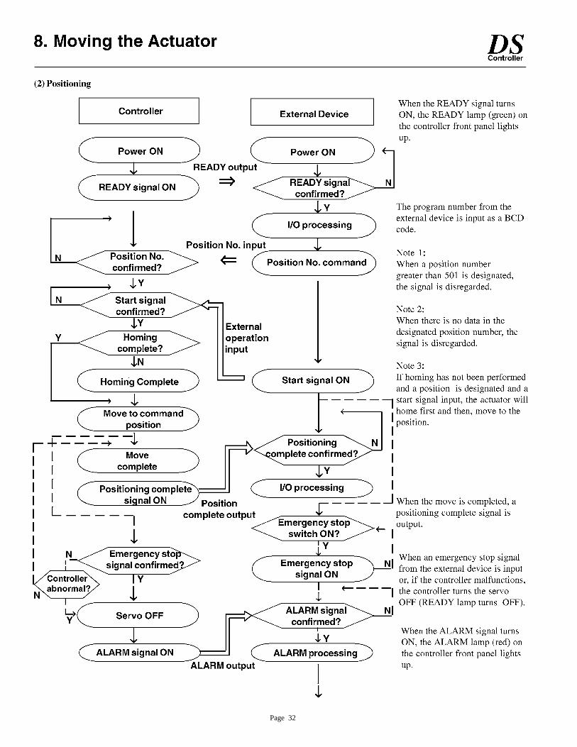
Page 32
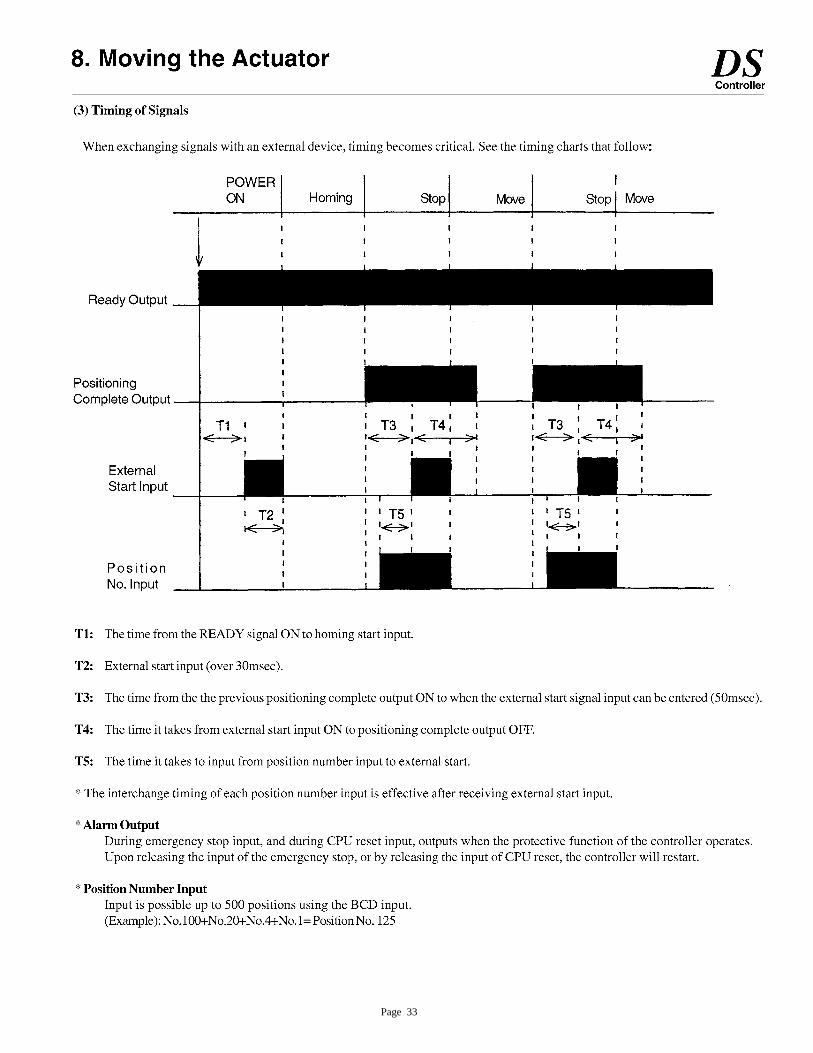
Page 33
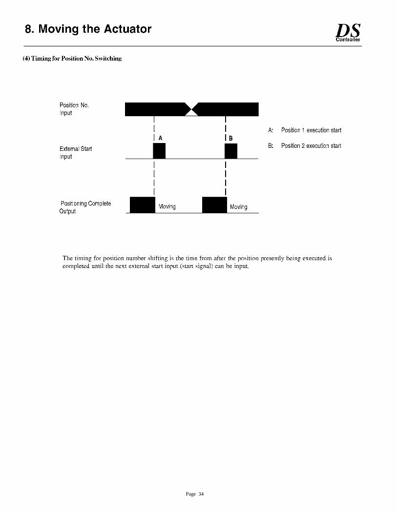
Page 34
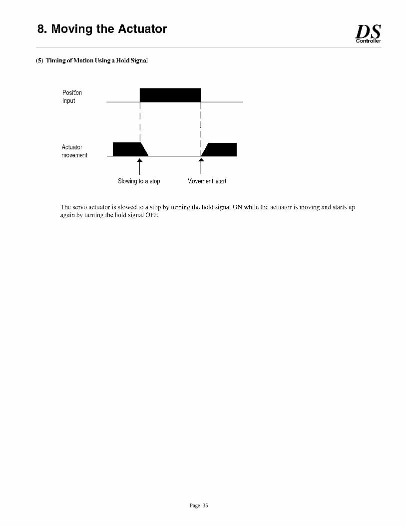
Page 35
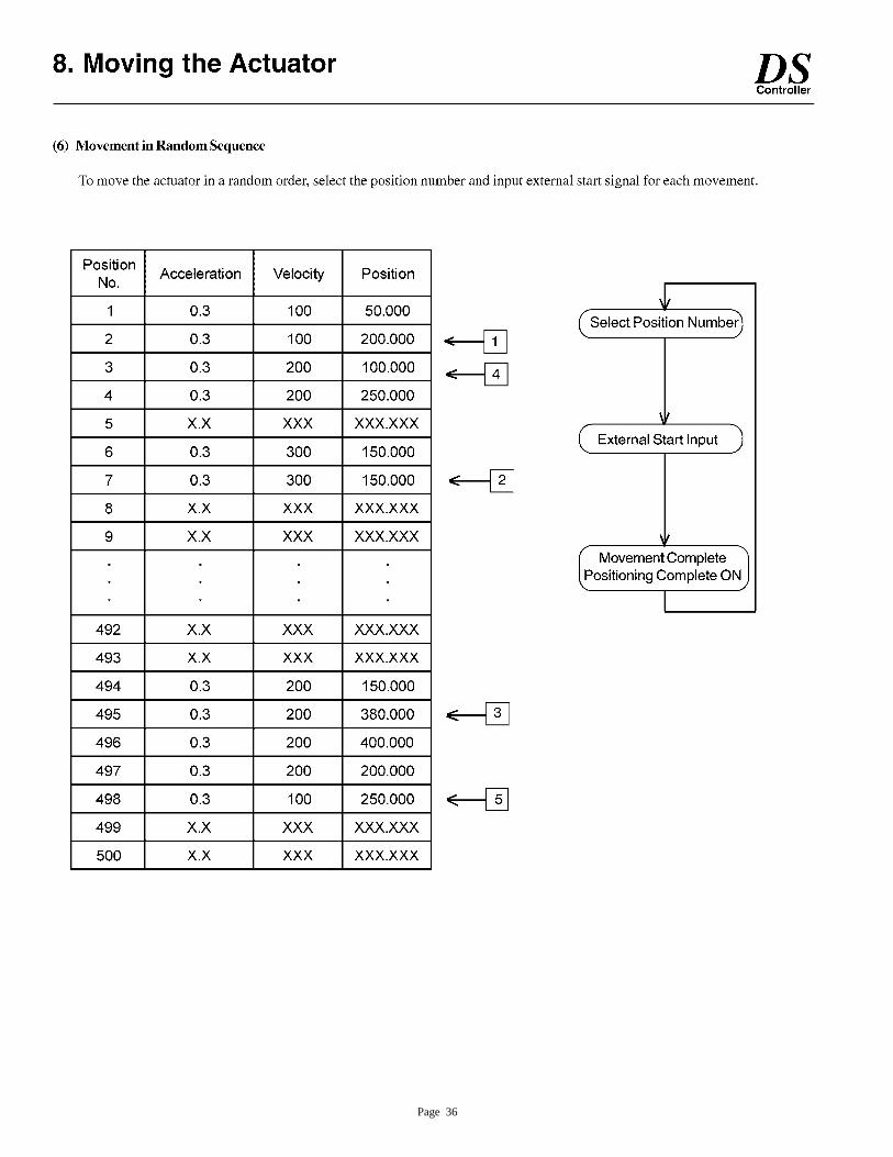
Page 36
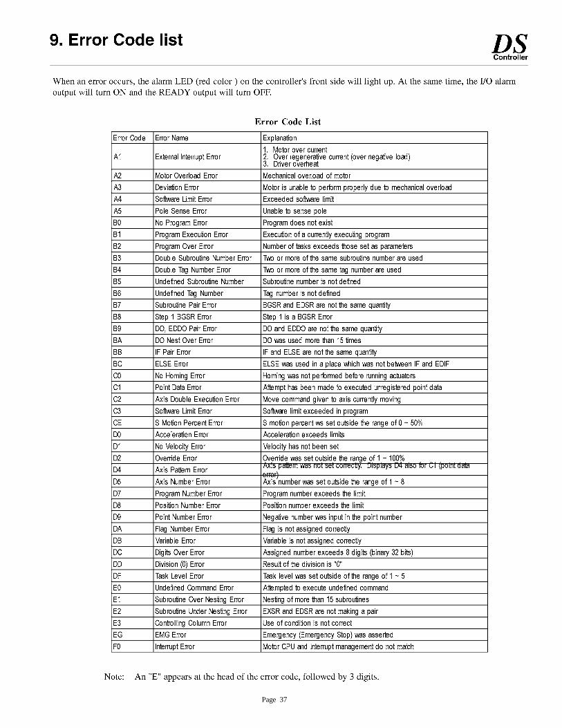
Page 37
Page 38
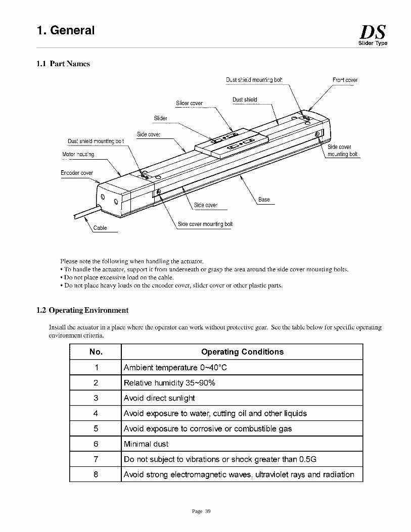
Page 39
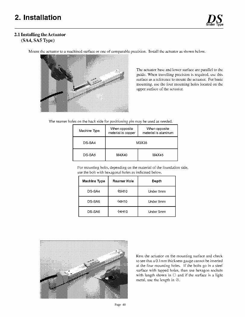
Page 40

Page 41

Page 42
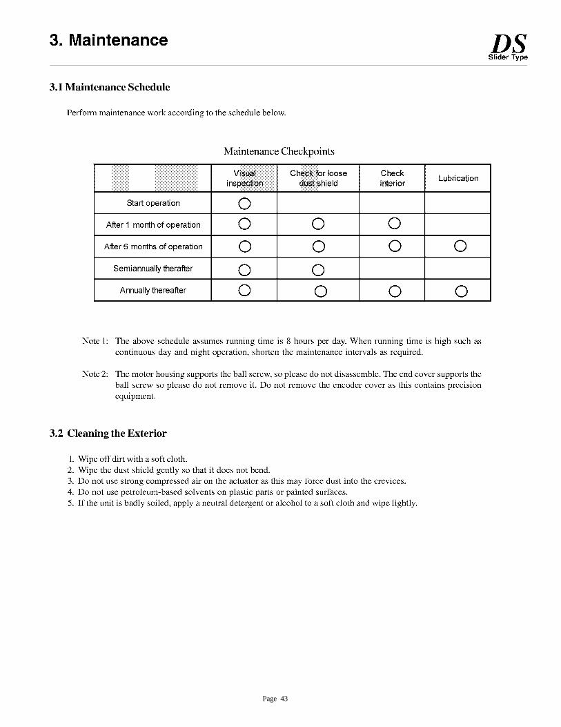
Page 43
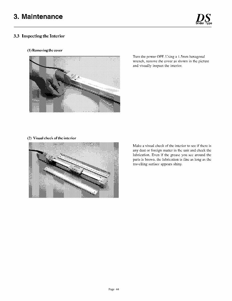
Page 44
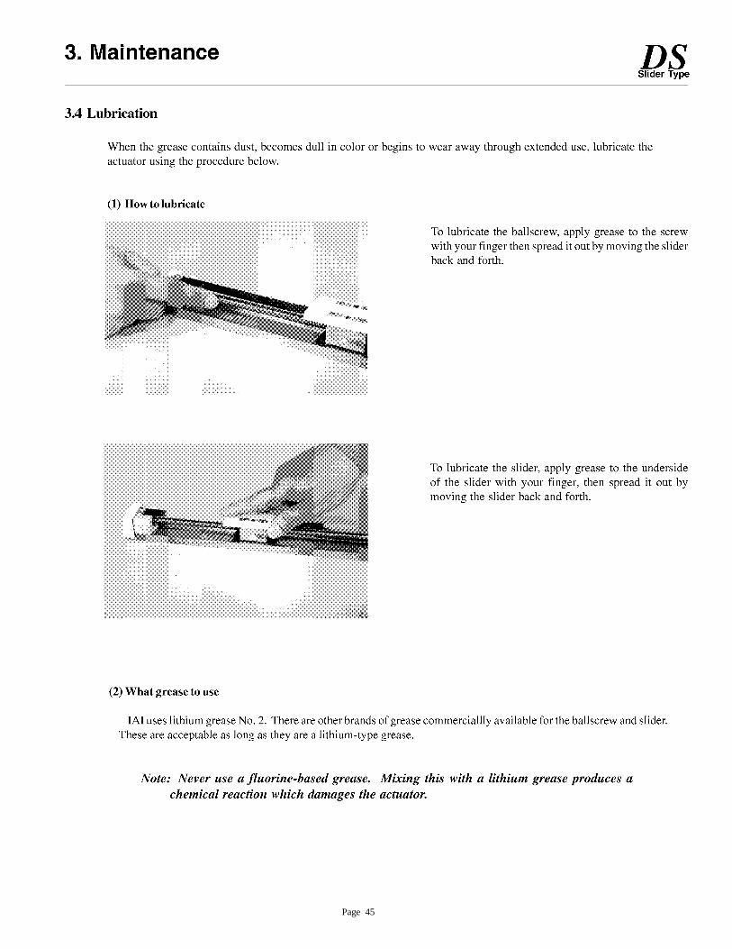
Page 45
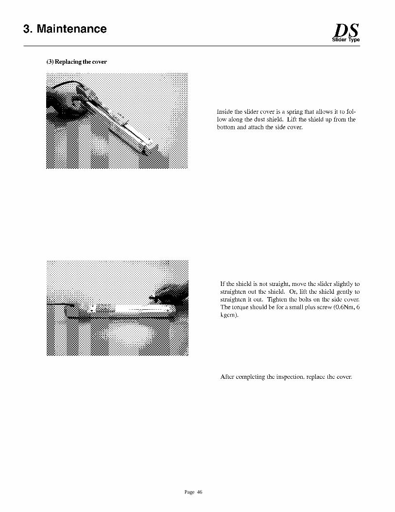
Page 46

Page 47
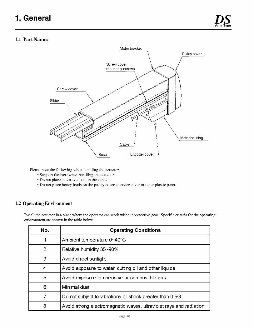
Page 48
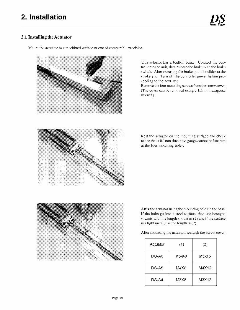
Page 49
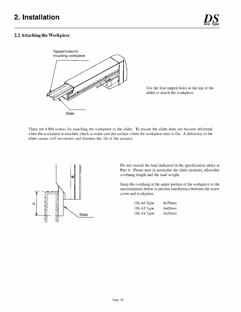
Page 50
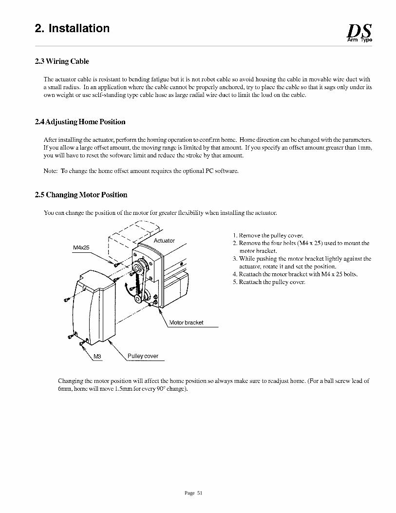
Page 51
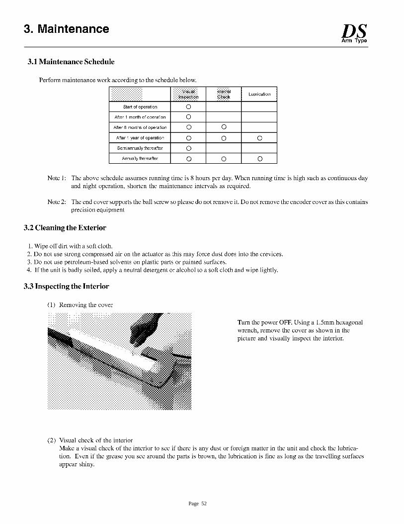
Page 52
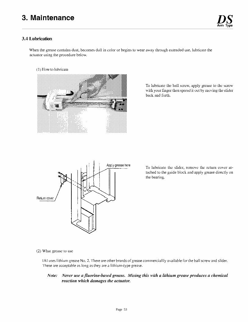
Page 53
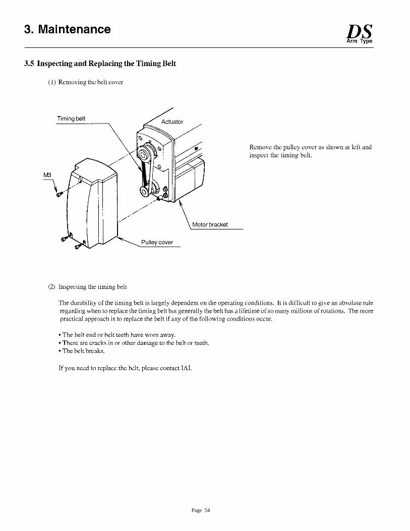
Page 54
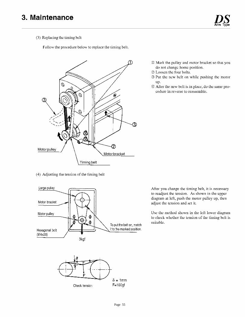
Page 55
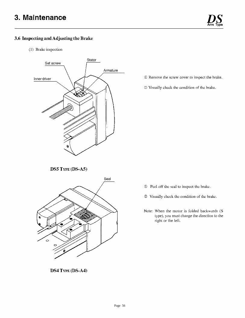
Page 56

Page 57
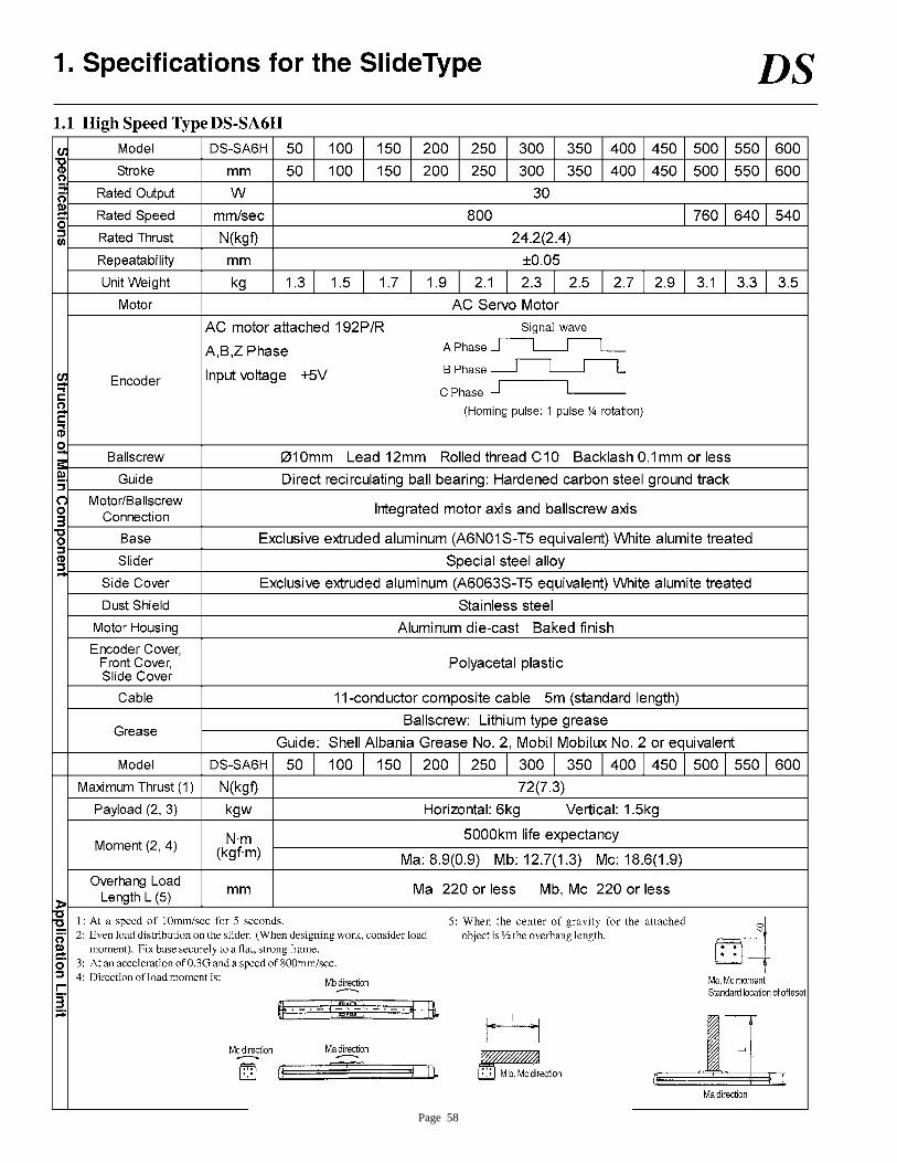
Page 58

Page 59
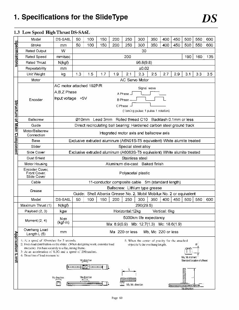
Page 60
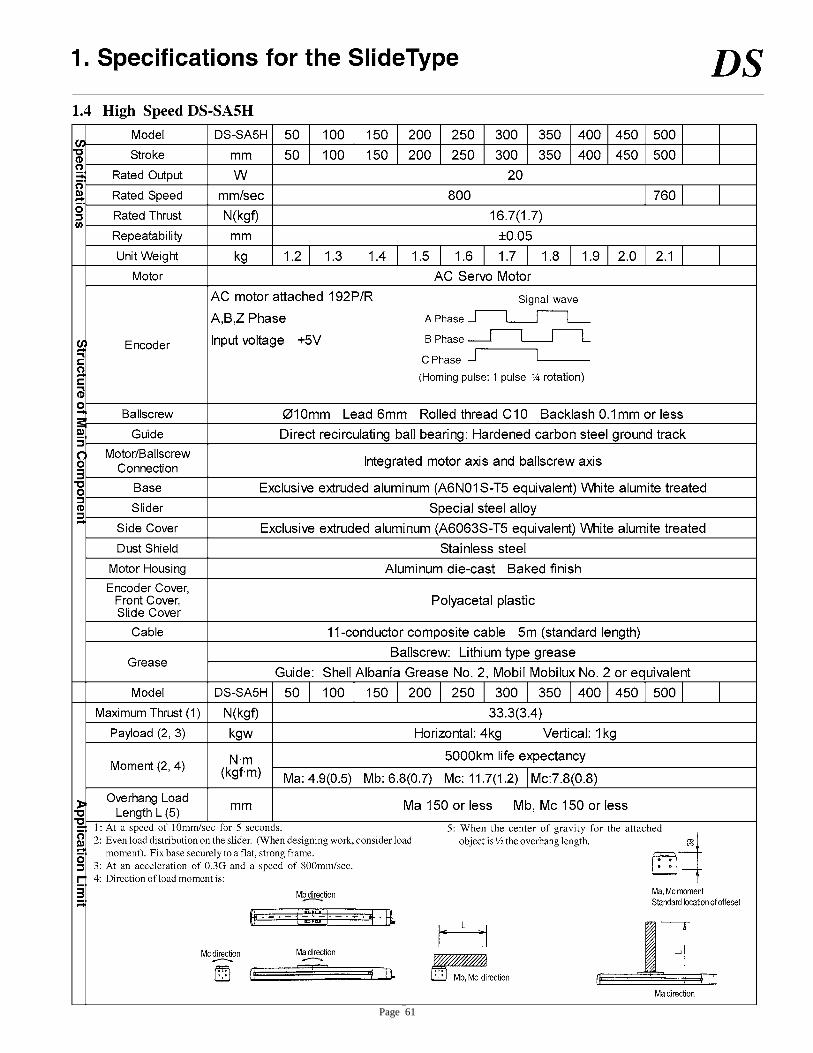
Page 61
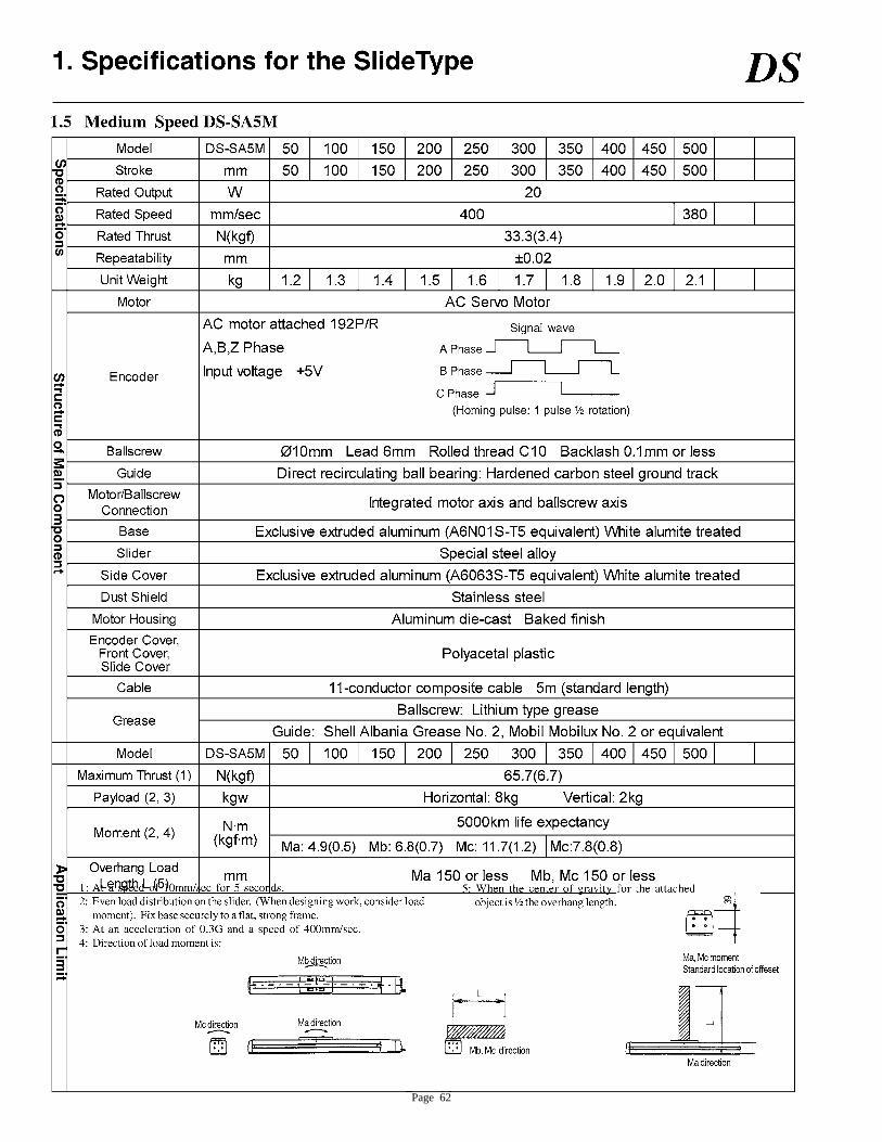
Page 62
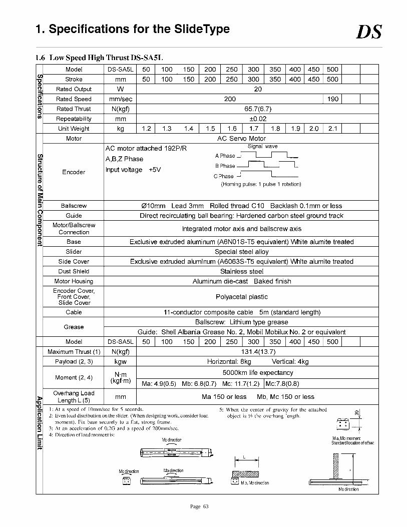
Page 63
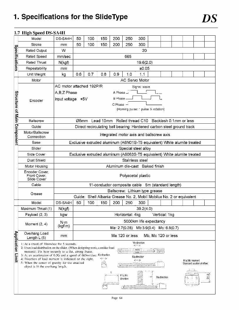
Page 64
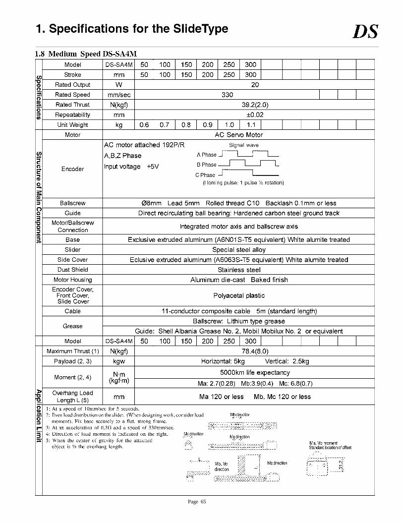
Page 65
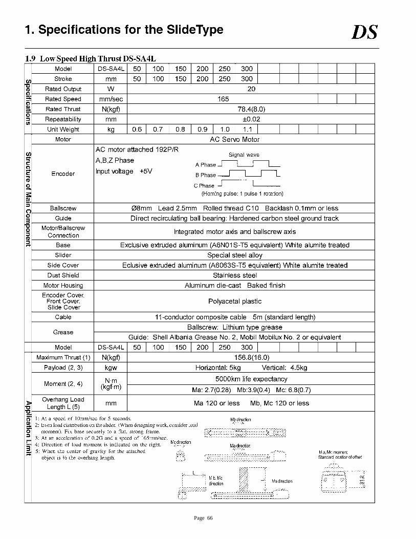
Page 66
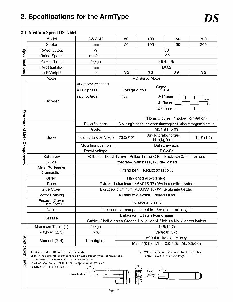
Page 67
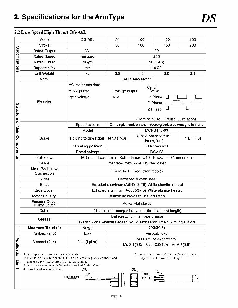
Page 68
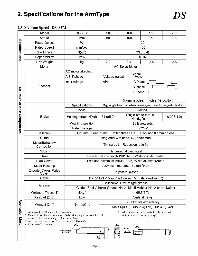
Page 69
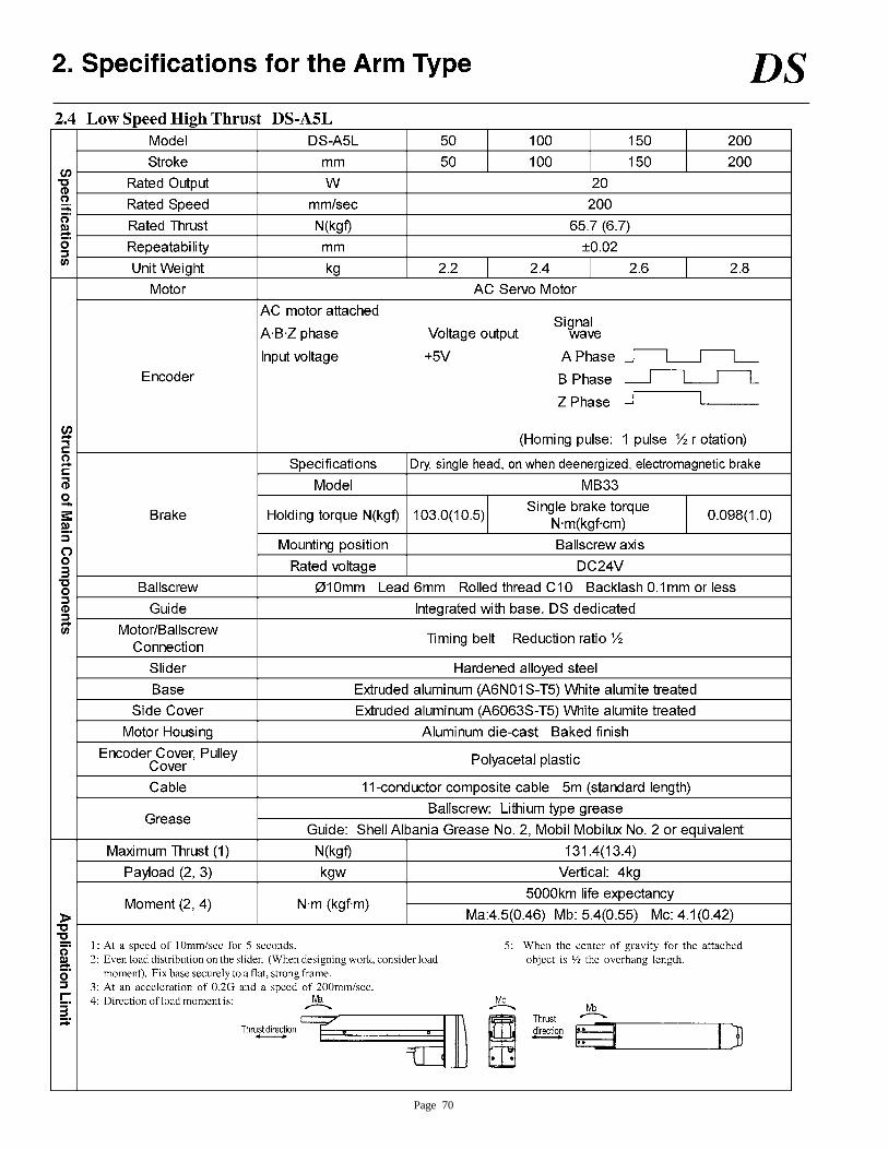
Page 70
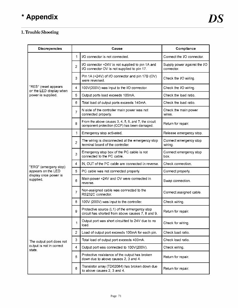
Page 71
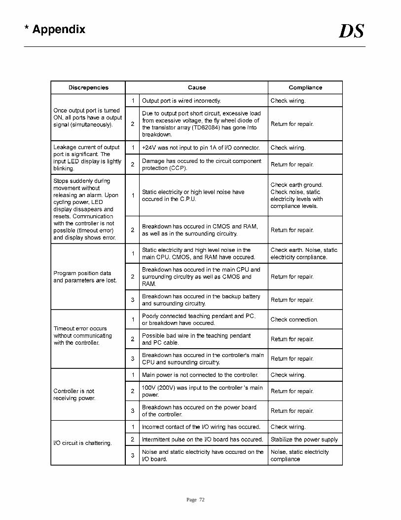
Page 72