cover.pptx - read-only - established 1970
TRANSCRIPT

Axton Isaly, Sebastian Deleon, Antonio Diaz, Moses Divaker,Ryan Earl, Lucas Murphy, Andrew Ortega
Faculty Advisor: Peter Ifju
Authors: [email protected]@[email protected] [email protected]@[email protected]@ufl.edu
University of FloridaUnmanned Aircraft Systems
Research ProgramP.O. Box 110450
Gainesville Florida 32611352.294.2829
uas.ifas.ufl.eduFaculty Advisor: [email protected]
FOILUNMANNEDUNMANNED
FOILPrototyping of a Single‐Mast Electric HydrofoilPrototyping of a Single‐Mast Electric Hydrofoil
ABSTRACT A unique, single-mast, electric, unmanned hydrofoil vessel was developed at the University of
Florida for survey and mapping (bathymetry) applications. A group of students familiar with
designing and building unmanned aircraft systems were intrigued with the recent development of
hydrofoil surfboards, such as the Lift eFoil. By combining the concept of the single-mast design
with modern drone autopilot technology, a unique vessel was developed that has advantages over
traditional small unmanned watercraft. The vessel is 72 inches long, 26 inches wide, and 42 inches
tall with a total weight of approximately 120 lb, making transport, launching, and operation
convenient. The advantages of this platform over a conventional watercraft are the reduced drag
associated with a hydrofoil and a more stable platform that allows a sensor (such as a camera or
sonar transducer) to traverse just under the water surface, at high speeds, unaffected by wind and
chop. Because of the efficiencies that the hydrofoil allows the vessel has a longer range and
operates for a longer duration for a given battery capacity or runs at higher speeds for a given
motor/battery power. The vessel also was designed with a telescoping mast, thus allowing it to be
launched in as little as 10 inches of water. This paper describes the design process that was
implemented, fabrication, testing, and validation in a real-world setting. The vessel has the
potential to perform a prescribed raster pattern to produce unmanned underwater surveys with
sonar or optical sensors.
1
Axton Isaly, Sebastian Deleon, Antonio Diaz, Moses Divaker, Ryan Earl, Lucas Murphy, and Andrew Ortega
UF: Unmanned Foil
Prototyping of a Single-Mast Electric Hydrofoil
I. ABSTRACT A unique, single-mast, electric, unmanned
hydrofoil vessel was developed at the University of
Florida for survey and mapping (bathymetry)
applications. A group of students familiar with
designing and building unmanned aircraft systems were
intrigued with the recent development of hydrofoil
surfboards, such as the Lift eFoil. By combining the
concept of the single-mast design with modern drone
autopilot technology, a unique vessel was developed
that has advantages over traditional small unmanned
watercraft. The vessel is 72 inches long, 26 inches wide,
and 42 inches tall with a total weight of approximately
120 lb, making transport, launching, and operation
convenient. The advantages of this platform over a
conventional watercraft are the reduced drag associated
with a hydrofoil and a more stable platform that allows
a sensor (such as a camera or sonar transducer) to
traverse just under the water surface, at high speeds,
unaffected by wind and chop. Because of the
efficiencies that the hydrofoil allows, the vessel has a
longer range and operates for a longer duration for a
given battery capacity or runs at higher speeds for a
given motor/battery power. The vessel also was
designed with a telescoping mast, thus allowing it to be
launched in as little as 10 inches of water. This paper
describes the design process that was implemented,
fabrication, testing, and validation in a real-world
setting. The vessel has the potential to perform a
prescribed raster pattern to produce unmanned
underwater surveys with sonar or optical sensors.
List of Acronyms
CAD Computer-Aided Design
CFD Computational Fluid Dynamics
IMU Inertial Measurement Unit
LiPo Lithium Polymer
OTS Off-the-shelf
PWM Pulse-Width Modulation
1 Find the UASRP online at: https://uas.ifas.ufl.edu/
II. INTRODUCTION By combining technologies from the recent
advances in the development of single-mast, electric
hydrofoil watercraft such as the hydrofoil surfboard Lift
eFoil [1], the University of Florida has developed an
unmanned hydrofoil watercraft, shown in Figure 1, that
can be used for a myriad of applications as a result of
fly-by-wire drone autopilot technology. The resulting
vessel, called the Unmanned Foil, was designed and
fabricated by a group of University of Florida students
in a tiered approach. The first phase was conducted by
a small group of students as part of the Mechanical
Engineering Capstone Design sequence. This design
was then refined and tested by members of the
University of Florida Unmanned Aircraft Systems
Research Program1 (UF UASRP). The team of student
authors is comprised of a combination of students from
the capstone design class and the UF UASRP.
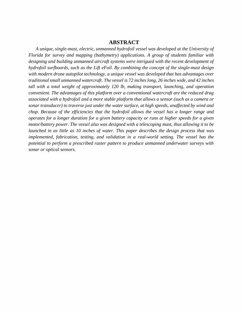
The Unmanned Foil, seen in Figure 1, is 72 inches
long, 26 inches wide, and 42 inches tall (with the mast
extended), with a total weight of approximately 120 lb,
making transport, launching, and operation convenient.
The advantages of this platform over a conventional
watercraft are the reduced drag associated with a
hydrofoil and a more stable platform that allows a
sensor (such as a camera or sonar transducer) to traverse
just under the water surface unaffected by wind and
chop. Because of the efficiencies that the hydrofoil
allows, the Unmanned Foil has a longer range and
operates for a longer duration for a given battery
Figure 1. Various views of the Unmanned Foil. A video
of the vessel in operation is available at:
https://www.youtube.com/watch?v=COIa1xe7tfw
2
capacity or runs at higher speeds for a given
motor/battery power.
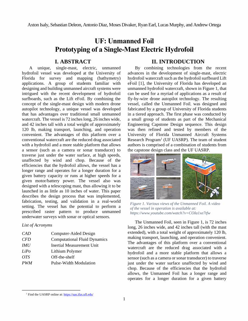
The underwater portion of the vessel (hydrofoil) is
similar to a fixed-wing airplane and is comprised of a
fuselage, wing, and vertical and horizontal stabilizers.
As shown in Figure 2, control of the vessel is
accomplished with underwater elevons (two control
surfaces on the outboard portion of the horizontal
stabilizers that mimic a combination of an elevator and
ailerons) that affect the pitch and roll. The wing
provides lift and the horizontal stabilizer and elevons
actively trim the vessel so that it remains level. A
vertical airfoil-shaped mast connects the hydrofoil to
the hull of the vessel. In operation, the vessel acts as an
inverted pendulum (similar to a Segway®) with 75% of
its weight in the mast and hull. Without the fly-by-wire
functionality of the autopilot, the vessel would be
unstable.
Figure 2. Pitch is controlled by coordinated rotation of the
outboard portion of the horizontal stabilizer (elevons) while
roll is controlled by alternate actuation of the elevons.
The Unmanned Foil utilizes an unmanned aircraft
grade Pixhawk® autopilot, equipped with an IMU
comprised of a 3-axis gyro, accelerometer, and
magnetometer. Pressure sensors mounted in the
fuselage of the vessel provide depth and velocity
feedback to the Pixhawk. Measurements from the
pressure sensors are used in a custom control algorithm
which lets the autopilot maintain the vessel at a set
elevation and speed. The vessel is also equipped with a
GPS unit so that it can accurately follow navigation
paths for linear or area coverage. The GPS data can be
synchronized with underwater images and sonar data to
map the sea-floor depth and create high-resolution
digital elevation models or traditional photo mosaics.
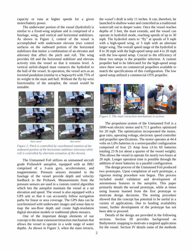
One of the important design elements of our
concept is the mast extension/retraction mechanism that
allows the vessel to operate in a wide range of water
depths. As shown in Figure 3, when the mast retracts,
the vessel’s draft is only 11 inches. It can, therefore, be
launched in shallow water and controlled as a traditional
watercraft out to deeper water. Once the vessel reaches
depths of 3 feet, the mast extends, and the vessel can
operate in hydrofoil mode, reaching speeds of up to 30
mph. The hydrofoil starts to “fly” at speeds of 8 mph
with a high-speed wing, or 5 mph with an alternate
larger wing. The overall speed range of the hydrofoil is
8 to 30 mph with the high-speed setup and 4 to 20 mph
with the low-speed setup. Crucial to the efficiency of
these two setups is the propeller selection. A custom
propeller had to be fabricated for the high-speed setup
since there were no commercial propellers available to
match the specifications of this configuration. The low
speed setup utilized a commercial OTS propeller.
Figure 3. The mast retraction mechanism in action.
The propulsion system of the Unmanned Foil is a
5000-watt electric motor and 6.71:1 gearbox optimized
for 20 mph. The optimization incorporated the motor,
gear ratio, operating voltage, electronic speed controller
and propeller specifications. The motor operates at 44.4
volts on LiPo batteries in a series/parallel configuration
comprised of four 23 Amp hour (A∙h) 6S batteries
totaling 23 lb (or about a quarter of the vessel weight).
This allows the vessel to operate for nearly two hours at
20 mph. Longer operation time is possible through the
addition of more batteries in a parallel configuration.
The design process of the Unmanned Foil produced
two prototypes. Upon completion of each prototype, a
rigorous testing procedure was begun. This process
included model validation and development of
autonomous features in the autopilot. This paper
primarily details the second prototype, while at times
using lessons learned from the first prototype to
motivate design decisions. The testing procedure
showed that the concept has potential to be useful in a
variety of applications. Due to funding availability
issues, further development of the prototype has not
been able to proceed.
Details of the design are provided in the following
sections. Section III provides background on
Bathymetric mapping to motivate a targeted application
for the vessel. Section IV details some of the methods
3
from statics and hydrodynamics that were used in the
early design stage. Section V details the design of the
powertrain. Section VI outlines the manufacturing
techniques used to fabricate the hull. The actuation
mechanisms of the vessel are described in Section VII.
Section VIII describes the electrical components and
autopilot software that were used to achieve autonomy.
Section IX describes the testing procedure that was used
to validate theoretical models and further develop the
software. Finally, Section X describes intended future
work. The reader is referred to the Appendix for a
labelled view of some of the components that are
mentioned in the subsequent sections.
Advantages of the hydrofoil concept
• Less wetted surface area than traditional boats
• Can run longer for a given battery capacity
• Can run faster for a given motor/battery power
• Rides level, even in choppy water
• Makes for a better, more stable camera platform
• GPS and communication through the hull
• Better for sonar mapping in shallow water since it
rides level
• Quieter than traditional boats
III. BATHYMETRIC MAPPING The University of Florida’s UASRP is an
interdisciplinary group of students and professors
developing drones and remote sensing technologies for
natural resource applications. Recently, the UASRP has
been focused on coastal and wetland mapping in order
to determine the responses to hydrological changes. To
acquire bathymetric data (or underwater mapping data),
the UASRP investigated potential survey vessels. An
autonomous survey vessel is desirable as traditional
underwater photogrammetry methods are quite labor
intensive, requiring a team of divers to capture the area
manually. Typically, humans are unaware of the
current, leading to nonuniform data. Most unmanned
survey vessels operate at slow speeds and are not
designed for the open ocean; they are affected by and
must actively correct for chop and waves [2]. Some
vessels are completely submerged, prohibiting
transmission of most radio signals, which is a huge
logistical hurdle for sending telemetry, control, and
navigation signals to the vessel [3].
The Unmanned Foil features unique characteristics
that make it advantageous when compared to traditional
methods of bathymetric data capture. The
characteristics of a submerged fuselage, stable flight,
wide range of speed, and a waterproof electronics
compartment allow it to host a variety of sensors. The
vessel is unaffected by chop, allowing for smooth sonar
data acquisition; it maintains consistent speed, allowing
camera triggering to be consistent; and its constant
depth provides uniform data between passes.
Transmission of signals is reliable since the hull is lifted
above the waterline. The hydrofoil’s sealed electric
propulsion system allows for data to be obtained in
sensitive areas typically inaccessible by boat. These
areas include protected marine environments and
drinking water reservoirs where a pollution risk
prohibits vessels that burn fossil fuels.
For this design iteration, we included compartments
sized for an RGB camera and a multibeam sonar
transducer in the fuselage of the vessel, which can be
coupled with the existing Global Navigation Satellite
System/Inertial Navigation System (GNSS/INS) unit
and processing computer in the electronics
compartment of the hull. The nosecone of the fuselage
can be configured to accommodate various payloads. A
camera mounted in this position will have unobstructed
visibility. The onboard autopilot enables camera
triggering by sending a PWM signal through an
accessory channel, which allows for acquisition of
photos based on a timer, or by GPS location.
Simultaneously, the autopilot is capable of logging
when the camera is triggered and the vessel’s GPS
coordinates, allowing for photos to be geo-tagged.
By combining sonar and photogrammetric data,
colorized 3D scans of a region can be produced. Sonar
systems are capable of recording to an onboard SD card
while simultaneously transmitting real time data via the
on-board telemetry link to an onshore processing
computer. Combined with a processing software, the
Unmanned Foil would be capable of producing real
time sonar maps while data collection is in progress.
This is advantageous to end-users since areas with data
gaps can be addressed and recaptured in situ, thereby
avoiding a costly second trip. By taking still images
with a camera, it is possible to achieve high resolution
photogrammetric processing in clear water for
applications such as seagrass and coral reef mapping
[4].
IV. HYDRODYNAMICS & STATICS
A. Equilibrium Analysis Equilibrium analysis was conducted to understand
the force and moment balance as a function of the
Unmanned Foil’s velocity. From the success of the Lift
eFoil, it was readily apparent that unmanned vessel
stability was achievable. To accomplish this, the vessel
dynamics first had to be understood in order to
4
distribute the mass of each component and size the
lifting surfaces for stable flight. For the Lift eFoil,
longitudinal and lateral balance is achieved by rider
weight-shifting, as opposed to our vessel where the
mass distribution is fixed, and balance is achieved
through the combination of thrust variation and
actuation of control surfaces. In the equilibrium
analysis, at any given speed, the starting point is a free
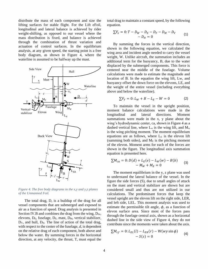
body diagram, as shown in Figure 4, where the
waterline is assumed to be halfway up the mast.
Figure 4. The free body diagrams in the x,y and y,z planes
of the Unmanned Foil.
The total drag, D, is a buildup of the drag for all
vessel components that are submerged and exposed to
air as a function of speed. Drag analysis is presented in
Section IV.B and combines the drag from the wing, DW,
elevons, DE, fuselage, DF, mast, DM, vertical stabilizer,
DV, and hull, DH. The line of action of the total drag,
with respect to the center of the fuselage, d, is dependent
on the relative drag of each component, both above and
below the water. By summing forces in the horizontal
direction, at any velocity, the thrust, T, must equal the
total drag to maintain a constant speed, by the following
equation.
∑𝐹𝑥 = 0: 𝑇 − 𝐷𝑊 − 𝐷𝐸 − 𝐷𝐹 − 𝐷𝑀 − 𝐷𝑉
− 𝐷𝐻 = 0 (1)
By summing the forces in the vertical direction,
shown in the following equation, we calculated the
wing area and incident angle needed to carry the vessel
weight, W. Unlike aircraft, the summation includes an
additional term for the buoyancy, B, due to the water
displaced by the submerged components. This force is
centered near the middle of the fuselage. Volume
calculations were made to estimate the magnitude and
location of B. In the equation the wing lift, Lw, and
buoyancy offset the down force on the elevons, LE, and
the weight of the entire vessel (including everything
above and below the waterline).
∑𝐹𝑌 = 0: 𝐿𝑊 + 𝐵 − 𝐿𝐸 − 𝑊 = 0 (2)
To maintain the vessel in the upright position,
moment balance calculations were made in the
longitudinal and lateral directions. Moment
summations were made in the x, y plane about the
wing’s hydrodynamic center, ca, shown in Figure 4 as a
dashed vertical line, where Lw is the wing lift, and Mw
is the wing pitching moment. The moment equilibrium
equations are as follows, where LE is the elevon lift
(summing both sides), and ME is the pitching moment
of the elevon. Moment arms for each of the forces are
shown in the figure. The longitudinal axis summation
equation is presented here.
∑𝑀𝑐𝑎 = 0: 𝐷(𝑑) + 𝐿𝐸(𝑒) − 𝐿𝑊(𝑤) − 𝐵(𝑏)
− 𝑀𝑊 + 𝑀𝐸 = 0 (3)
The moment equilibrium in the y, z plane was used
to understand the lateral balance of the vessel. In the
figure the side forces (S), due to small angles of attack
on the mast and vertical stabilizer are shown but are
considered small and thus are not utilized in our
calculations. The predominant forces that keep the
vessel upright are the elevon lift on the right side, LER,
and left side, LEL. This moment analysis was used to
estimate the permissible tilt angle, 𝜙, as a function of
elevon surface area. Since most of the forces pass
through the fuselage central axis, shown as a horizontal
dashed line in the side view of Figure 4, they do not
contribute since the moments were taken about the axis.
∑𝑀𝑐𝑓 = 0: 𝐿𝐸𝐿(𝑙) − 𝐿𝐸𝑅(𝑟) − W(𝑤𝑦 sin 𝜙)
− 𝑆(𝑠) = 0 (4)
5
here 𝑟 = 𝑙 and, if we neglect side force S, this reduces
to
(𝐿𝐸𝐿 − 𝐿𝐸𝑅)(𝑙) − 𝑊(𝑤𝑦 sin 𝜙) = 0 (5)
The equilibrium equations were implemented in a
spreadsheet to understand the significance of the mass
of each component. To have the ability to set the
location of the center of mass, the battery position was
adjustable. Since batteries were expected to be on the
order of 25% of the entire mass, small position
adjustments of the battery had a significant effect on the
longitudinal stability. The dimensions wx and b define
the static margin of the vessel. The objective was to
have a positive static margin, but adjustable during field
testing and gain tuning.
B. Power Polar Determination To estimate the powertrain requirements for the
Unmanned Foil, the power required to overcome the
vessel’s drag at a given speed must first be calculated.
This power required estimation first requires an
estimation of the zero lift drag coefficient (CD0), also
known as the parasite drag coefficient. This value was
determined using the traditional component-by-
component drag buildup. In the component-by-
component drag buildup, the equivalent flat plate drag
area is calculated, and then weighted and summed to
obtain the total vessel drag. The equivalent flat plate
drag area for each component (𝑓𝑖) is
𝑓𝑖 = 𝑆𝑤𝑒𝑡𝑖× 𝐶𝑓𝑖
× 𝐹𝐹𝑖 × 𝑄𝑖 (6)
where 𝑖 is the component index, 𝑆𝑤𝑒𝑡 is the component
wetted area, 𝐶𝑓 is the component skin friction
coefficient, 𝐹𝐹 is the component form factor and 𝑄 is
the component interference factor. The skin friction
coefficient was obtained using the Prandtl Low
Reynolds number equation [5]:
𝐶𝑓 =0.074
𝑅𝑒1/5 (7)
where the Reynolds number is based on the
characteristic length of each component, such as the
chord, or fuselage length. The component form factors
(FF) are based on the Hoerner empirical correlations
[6]. These values represent the drag produced by
different aerodynamic shapes:
𝐴𝑒𝑟𝑜 𝑆𝑢𝑟𝑓𝑎𝑐𝑒𝑠 & 𝑃𝑟𝑜𝑝𝑒𝑙𝑙𝑒𝑟 𝐹𝑜𝑟𝑚 𝐹𝑎𝑐𝑡𝑜𝑟
= 1 + 2 (𝑡
𝑐) + 60 (
𝑡
𝑐)
4
(8)
𝐹𝑢𝑠𝑒𝑙𝑎𝑔𝑒 𝐹𝑜𝑟𝑚 𝐹𝑎𝑐𝑡𝑜𝑟
= 1 +1.5
(𝑙 𝑑⁄ )1.5+
7
(𝑙 𝑑⁄ )3
(9)
In the above equations, t/c is the wing thickness-to-
chord ratio (e.g 12% for a NACA0012), and l/d is the
fuselage fineness ratio, where l is the fuselage length
and d is the fuselage diameter. Lastly, the interference
factor (Q) represents the drag produced by interaction
between different components. Appropriate
interference factors were obtained from Gudmunssen
and are estimates based on historic data [7]. The value
of 1.3 was chosen since this value is typical for un-
filleted wing intersections.
Each component’s equivalent flat plate area is then
summed and normalized by vessel reference area and
added to a miscellaneous drag coefficient term to obtain
the total zero-lift drag coefficient:
𝐶𝐷0 =1
𝑆𝑟𝑒𝑓∑ 𝑓𝑖
𝑁
𝑖=1
+ 𝐶𝐷𝑚𝑖𝑠𝑐 (10)
The miscellaneous drag term (𝐶𝐷𝑚𝑖𝑠𝑐) serves as an
important “catch-all” to capture the effects of items that
are hard to take into account (e.g. retraction mechanism,
out-of-water boat hull, etc.) This term is hard to model
a-priori, so a correction factor of 10% of the total vessel
drag coefficient is used. The vessel reference area (𝑆𝑟𝑒𝑓)
chosen was the wing planform area. N is the total
number of components.
To compute the values for the skin friction
coefficient, form factors and wetted areas, knowledge
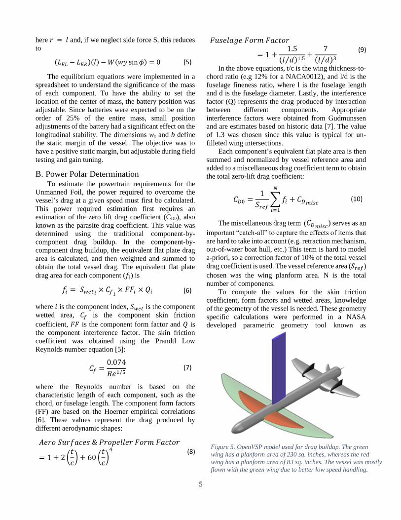
of the geometry of the vessel is needed. These geometry
specific calculations were performed in a NASA
developed parametric geometry tool known as
Figure 5. OpenVSP model used for drag buildup. The green
wing has a planform area of 230 sq. inches, whereas the red
wing has a planform area of 83 sq. inches. The vessel was mostly
flown with the green wing due to better low speed handling.
6
OpenVSP [8]. The OpenVSP model of the vessel is
shown in Figure 5.
Table I: Vessel Drag Buildup
Lastly, the total drag acting on the vessel is based
on both zero-lift drag/parasite drag and lift-induced
drag. Written in coefficient form:
𝐶𝐷 = 𝐶𝐷0 +𝐶𝐿
2
𝜋𝐴𝑅𝑒 (11)
where AR is the wing aspect ratio, e is the Oswald
efficiency and CL is the operating lift coefficient. Since
the objective of this effort would be to estimate the
motor requirements, the power required was obtained
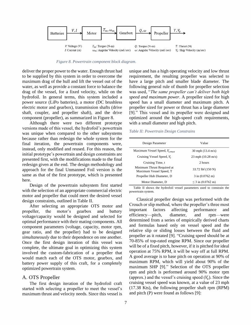
using the drag information. The power required was
obtained by calculating the force balance acting on the
hydrofoil in steady wing-borne flight (i.e. lift = weight,
thrust = drag) and then was multiplied by the vessel
speed. This analysis was conducted for the larger wing
hydrofoil shown in Figure 5 and has led to Figure 6.
Figure 6 shows that the measured power data
matches the predicted power polar very well. Power
requirements substantially increase as the vessel passes
through 6 mph. comparing the power required at 6 mph
to 12 mph, we see that there is a 4.5x increase in the
power required with a 2x increase in speed.
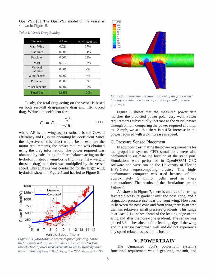
C. Pressure Sensor Placement In addition to estimating the power requirements for
the propulsion system, CFD simulations were also
performed to estimate the location of the static port.
Simulations were performed in OpenFOAM CFD
software and were run on the University of Florida
HiPerGator supercomputing cluster. This high-
performance computer was used because of the
approximately 5 million cells used in these
computations. The results of the simulations are in
Figure 7.
As shown in Figure 7, there is an area of a strong,
favorable pressure gradient over the nose cone, and a
stagnation pressure rise near the front wing. However,
in-between the nose cone and front wing there is an area
that has relatively small pressure gradients. This range
is at least 2.14 inches ahead of the leading edge of the
wing and after the nose-cone gradient. The sensor was
placed 3.3 inches ahead of the leading edge of the wing
and this sensor performed well and did not experience
any speed related issues at this location.
V. POWERTRAIN The Unmanned Foil’s powertrain system’s
functional requirement was to generate, transmit, and
Component ∆ CD0 % of Total CD0
Main Wing 0.021 37%
Stabilizer 0.008 14%
Fuselage 0.007 12%
Mast 0.010 18%
Vertical
Stabilizer 0.001 2%
Wing Fences 0.002 4%
Propeller 0.002 3%
Miscellaneous 0.006 10%
Total CD0 0.0555 100%
Figure 6. Hydrodynamic power required for wing-borne
flight. Power data (∙) measurements were converted from
raw electrical power measurements to vessel hydrodynamic
power assuming ηprop = 0.75, ηmotor = 0.90 & ηelectrical = 0.95.
Figure 7. Streamwise pressure gradient of the front wing /
fuselage combination to identify areas of small pressure
gradients.
7
deliver the proper power to the water. Enough thrust had
to be supplied by this system in order to overcome the
maximum drag of the hull and lift the vessel out of the
water, as well as provide a constant force to balance the
drag of the vessel, for a fixed velocity, while on the
hydrofoil. In general terms, this system included a
power source (LiPo batteries), a motor (DC brushless
electric motor and gearbox), transmission shafts (drive
shaft, coupler, and propeller shaft), and the drive
component (propeller), as summarized in Figure 8.
Although there were two different prototype
versions made of this vessel, the hydrofoil’s powertrain
was unique when compared to the other subsystems
because rather than redesign the whole system for the
final iteration, the powertrain components were,
instead, only modified and reused. For this reason, the
initial prototype’s powertrain and design constraints are
presented first, with the modifications made to the final
redesign given at the end. The design methodology and
approach for the final Unmanned Foil version is the
same as that of the first prototype, which is presented
here.
Design of the powertrain subsystem first started
with the selection of an appropriate commercial electric
motor and propeller that could meet the desired vessel
design constraints, outlined in Table II.
After selecting an appropriate OTS motor and
propeller, the motor’s gearbox and battery
voltage/capacity would be designed and selected for
optimal performance with their mating components. All
component parameters (voltage, capacity, motor rpm,
gear ratio, and the propeller) had to be designed
simultaneously due to their dependence on one another.
Once the first design iteration of this vessel was
complete, the ultimate goal in optimizing this system
involved the custom-fabrication of a propeller that
would match each of the OTS motor, gearbox, and
battery power supply of this craft, for a completely
optimized powertrain system.
A. OTS Propeller The first design iteration of the hydrofoil craft
started with selecting a propeller to meet the vessel’s
maximum thrust and velocity needs. Since this vessel is
unique and has a high operating velocity and low thrust
requirement, the resulting propeller was selected to
have a large pitch and smaller blade diameter. The
following general rule of thumb for propeller selection
was used, “The same propeller can’t deliver both high
speed and maximum power. A propeller sized for high
speed has a small diameter and maximum pitch. A
propeller sized for power or thrust has a large diameter
[9].” This vessel and its propeller were designed and
optimized around the high-speed craft requirements,
with a small diameter and high pitch.
Table II: Powertrain Design Constrains
Table II shows the hydrofoil vessel parameters used to constrain the powertrain system.
Classical propeller design was performed with the
Crouch or slip method, where the propeller’s three most
important factors affecting performance and
efficiency—pitch, diameter, and rpm—were
determined from a series of empirically derived charts
and formulas based only on vessel speed and the
relative slip or sliding losses between the fluid and
propeller as it rotated [9]. “Cruising speed should be at
70-85% of top-rated engine RPM. Since our propeller
will be of a fixed pitch, however, if it is pitched for ideal
operation at 75% RPM, it will be way off at full RPM.
A good average is to base pitch on operation at 90% of
maximum RPM, which will yield about 90% of the
maximum SHP [9].” Selection of the OTS propeller
rpm and pitch is performed around 90% motor rpm
(approx.) and the vessel’s cruising speed (𝑉𝑠). Since the
cruising vessel speed was known, at a value of 23 mph
(17.38 Kts), the following propeller shaft rpm (RPM)
and pitch (P) were found as follows [9]:
Design Parameter Value
Maximum Vessel Speed, 𝑉𝑠,𝑚𝑎𝑥 30 mph (13.4 m/s)
Cruising Vessel Speed, 𝑉𝑠 23 mph (10.28 m/s)
Cruising Time, t 2 hours
Minimum Thrust Required at
Maximum Vessel Speed, T 33.72 lbf (150 N)
Propeller Hub Diameter, D 3 in (0.0762 m)
Motor Diameter, D ≤ 3 in (0.0762 m)
Figure 8. Powertrain component block diagram.
8
𝑃 = 𝐾𝑡𝑠 × 1215.6
𝑅𝑃𝑀 × (1 − 𝑆𝑙𝑖𝑝𝐴) (12)
Through a series of iterations, the propeller shaft
rpm was (initially) chosen to be 1700 rpm, thus giving
a prop pitch of 17.14 inches, for a slip of 27.50%. The
apparent slip (SlipA) is a function of only vessel speed
and was found using the following [9]
𝑆𝑙𝑖𝑝 = 1.4 ÷ 𝐾𝑡𝑠0.57 (13)
It should be noted that although slip is presented
here as only a function of vessel speed, the type of boat
hull and its associated drag also influence the
propeller’s slip. For example, similar extremely fast
(over 90 knots) hydroplanes have low slip values, at
around 7% [9]. Were this lower propeller slip value of
7% to be used for the design (for the same propeller rpm
of 1700), a pitch of only 13.36 inches would be required
of the propeller.
“Diameter is the most important factor in
determining the amount of power a propeller absorbs
[9].” For this reason, the propeller diameter was
determined around 100% of maximum RPM, and not
around a lower rpm so that it did not hold down the
motor rpm and vessel speed (underpropping). Diameter
(D) is then calculated from maximum propeller rpm
(RPM) and horsepower at the propeller (SHP) using [9]
𝐷 = 632.7 × 𝑆𝐻𝑃0.2
𝑅𝑃𝑀0.6 (14)
Table III: OTS Propeller Summary
Parameter Optimum (in) OTS Spec
(in) OTS Prop
Pitch, P 13.36 - 17.14 15
Diameter, D 10.15 10.125
Hub Diameter, DH
3 3.25
Table III shows the OTS prop is a close match for this design.
For a 5000 W (6.71 HP) motor and max propeller
speed of 1783 rpm, this yields an optimum propeller
diameter of 10.15 inches. [Note: a gearbox is to be used
in this design, and its efficiency is estimated at 90%, for
a true SHP value of 4500 W or 6.03 HP.]
The OTS propeller chosen is summarized in Table
III. The pitch is in the middle of the calculated slip
range, and the blade outer diameter is a close match.
The hub diameter (DH) is similar to that of the fuselage
(3 inches) for minimizing drag, and the propeller
attaches with a splined shaft for easy
assembly/disassembly. The prop material is aluminum
and has more than the required strength for this low
thrust vessel, as well as the proper corrosion resistance
for this application.
B. OTS Motor and Gearbox When selecting the motor for the hydrofoil, similar
hobby-grade RC boat motor-gearbox combinations
were used for comparison. Dimensionally, the motor-
gearbox had to fit inside the motor pod tube, which is
housed within the fuselage, and have a diameter less
than 3 inches. The hydrofoil application required a high
rpm, high wattage DC motor, that could have a gearbox
attached to it in order to gear up the output torque
necessary for the propeller, while still operating at a
high rpm for optimal efficiency and low continuous
current draw. A brushless motor was desired over a
brushed one for better efficiency and durability. The
OTS motor and gearbox selected are summarized in
Table IV.
Table IV: OTS Motor-Gearbox Summary
Parameter Value OTS Motor-Gearbox
Model No. Neu2230-12
Turns 1.5Y
KV (RPM/V) 485
R (Ω) 0.007
Max RPM/ Max Power (W)/ Max Voltage (V)
40,000/10,000/72
𝐼0 at 10 V (A) 1.80
Continuous Power (W)
5,000
P62 Gearbox Ratio 6.71:1
Table IV shows the specs for the brushless DC motor-gearbox.
From these motor parameters, the torque vs.
speed/power/efficiency plots of this motor were found
to determine the best operating rpm to match the
propeller and maximize motor efficiency/minimize
current draw. Basic electric motor relations of voltage
(15), torque (16), 𝐾𝑇 (17), 𝐾𝑣 (18), and power (19) are
given below
𝑉 = 𝐼𝑅 + 𝐾𝑒𝜔 (15)
𝑇 = 𝐾𝑇𝐼 (16)
𝐾𝑇 = 60
2𝜋𝐾𝑣 (17)
𝐾𝑣 =
1
𝐾𝑒−𝑟𝑝𝑚 (18)
9
𝑃 = 𝑇𝜔 (19)
By rearranging and substituting (16) through (18)
into (15), the motor overload line for a given rpm (n) as
a function of only torque (T) can be found. For a voltage
of 22.2 V and the motor parameters in Table IV, (15) is
further simplified to the following for our motor
𝑛 = 10,767 𝑟𝑝𝑚 − (172.43 𝑟𝑝𝑚
𝑁 ∙ 𝑚) 𝑇 (20)
Next, motor efficiency is defined in (21) using
torque, speed, voltage, and total current (load and no-
load). Total current is defined by (22) from the no-load
current (𝐼0)
𝜂𝑚𝑜𝑡𝑜𝑟 =
𝑇𝜔
𝑉𝐼𝑡𝑜𝑡𝑎𝑙 (21)
𝐼𝑡𝑜𝑡𝑎𝑙 = 𝐼0 + 𝐼 (22)
Using (22) in (21), the motor efficiency for a given
rpm and torque value is given for the OTS motor
𝜂𝑚𝑜𝑡𝑜𝑟 =
𝑇𝑛
(381.6 + 10,767𝑇) (23)
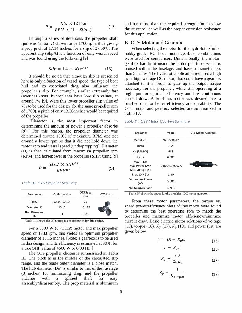
Plots of the motor overload, power, and efficiency
as a function of torque are shown together in Figure 9,
as well as the optimal operating points for rpm, torque,
power, and efficiency.
The motor operating point was set to properly
match the OTS propeller design rpm, as well as have the
motor operate near its most efficient point, as is
summarized in Table V.
Table V: OTS Motor & 6.71:1 Gearbox Summary
Parameter Symbol Cruising Speed, 23
mph (10.28 m/s)
Maximum Possible
Value
Motor Speed 𝑛𝑚 10,267 rpm 10,767 rpm
Propeller Speed 𝑛𝑝 1,700 rpm 1,783 rpm
Motor Torque 𝑇𝑚 2.9 N∙m 62.4 N∙m
Propeller Torque 𝑄 17.5 N∙m 376.8 N∙m
Motor Efficiency 𝜂𝑚𝑜𝑡𝑜𝑟 94.2 % 95.3 %
Table V shows the motor-gearbox values at cruising speed match the
previously designed OTS propeller and are at a high motor efficiency for this hydrofoil design.
The gearbox used with this motor had a 6.71:1 ratio.
This relatively high ratio was chosen to have the motor
operate near its maximum efficiency point (high rpm)
yet still have enough torque to spin the propeller. Gear
ratio torque and rpm calculations were found from (24),
conservatively assuming a 90% efficient gearbox,
𝜂𝑔𝑒𝑎𝑟𝑏𝑜𝑥 and where 𝜔𝑚
𝜔𝑝⁄ = 6.71
𝑇𝑚𝜔𝑚𝜂𝑔𝑒𝑎𝑟𝑏𝑜𝑥 = 𝑄𝜔𝑝 (24)
C. Batteries The selection of the power source for the hydrofoil
was constrained around minimizing hull weight, while
still ensuring a 2-hour runtime at the cruising speed was
achieved. As a result, lightweight, LiPo electric
batteries were selected over other battery or fuel
alternatives.
The design of the amount of voltage and capacity
for these battery packs came from the rest of the
powertrain components alone—motor, gearbox, and
propeller torque—operating at the cruising conditions.
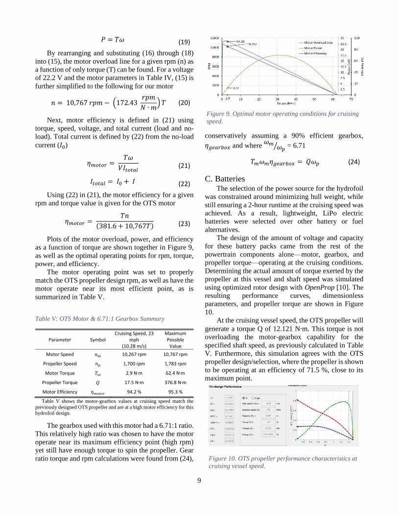
Determining the actual amount of torque exerted by the
propeller at this vessel and shaft speed was simulated
using optimized rotor design with OpenProp [10]. The
resulting performance curves, dimensionless
parameters, and propeller torque are shown in Figure
10.
At the cruising vessel speed, the OTS propeller will
generate a torque Q of 12.121 N∙m. This torque is not
overloading the motor-gearbox capability for the
specified shaft speed, as previously calculated in Table
V. Furthermore, this simulation agrees with the OTS
propeller design/selection, where the propeller is shown
to be operating at an efficiency of 71.5 %, close to its
maximum point.
Figure 10. OTS propeller performance characteristics at
cruising vessel speed.
Figure 9. Optimal motor operating conditions for cruising
speed.
10
From (24) and (16), the hydrofoil will require a
continuous motor supply current of 101.9 A (powertrain
only) at cruising speed. At a 2-hour runtime, this
requires a battery capacity of 203.9 A∙h. For this
propeller torque and current, the supply voltage
necessary is then calculated from (15). This is found to
be 21.86 V. As a result, a 22.2 V 6S LiPo battery was
selected for the hydrofoil battery, summarized in Table
VI.
Table VI: Battery Summary
Parameter Value Battery
Model No. LiPo 23,000 6S 22.2 V
Voltage 22.2 V
Capacity 23 A∙h
Type LiPo; 6 Cells, in Series
Discharge Rate 25C
Weight 2478 g (5.46 lb)
Table VI shows the specs for the LiPo batteries.
In order to achieve a 2-hour runtime, 9 of these
batteries would be wired in parallel to get 207 A∙h and
exceed the 203.9 A∙h calculated for the capacity
required for the motor at cruising speed.
Table VII: Redesigned Hydrofoil Motor
Parameter Prototype #1 Prototype #2
Motor 5000 W, 485 KV
NeuMotor 5000 W, 240 KV
NeuMotor
Gearbox 6.71:1 ratio 6.71:1 ratio
Voltage 22.2 V 44.4 V
Motor No-Load RPM
10,767 10,656
Motor Stall Torque
62.44 N∙m 50.47 N∙m
Max Prop RPM 1,783 1,590
Co
nti
nu
ou
s C
urr
ent
Dra
w,
I
5 mph 77.8 A 39.1 A
10 mph 83.8 A 41.9 A
15 mph 93.3 A 46.6 A
20 mph 101.8 A 50.9 A
25 mph 111.0 A 55.4 A
30 mph 121.4 A 60.5 A
Table VII shows that the redesigned motor for prototype #2 has a current
draw of half that of prototype #1 across all vessel speeds. The doubled voltage allows the same approximate motor speed to be reached.
D. Unmanned Foil (Second Prototype) After initial testing and proof of concept, the
hydrofoil prototype was redesigned to improve upon the
first iteration. Namely for the powertrain, the motor
current draw and propeller were completely redesigned
for better longevity and improved efficiencies.
To lower the continuous current draw of the electric
motor, the excitation voltage was doubled from 22.2 V
to 44.4 V and the motor Kv was approximately halved
from 485 to 240. Lowering the motor’s Kv increases its
torque constant KT, shown in (17). Since KT is also
inversely proportional to current I (16), this will have
the intended effect of halving the current draw. By
doubling the voltage, the propeller shaft was able to still
be spun at approximately the same speed. This design
improvement is recalculated and summarized for the
rewound motor in Table VII.
The Unmanned Foil was also optimized around a
lower cruising speed, at 20 mph (8.94 m/s), than the first
prototype. At this speed for a 2-hour runtime, the
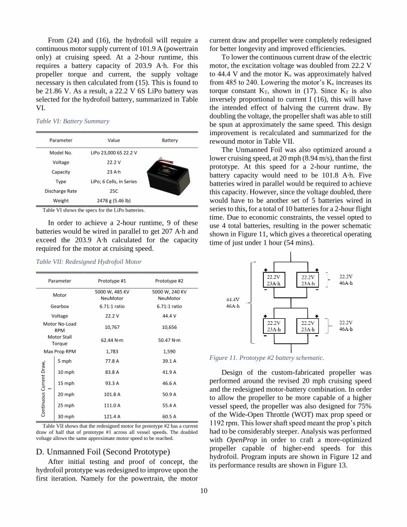
battery capacity would need to be 101.8 A∙h. Five
batteries wired in parallel would be required to achieve
this capacity. However, since the voltage doubled, there
would have to be another set of 5 batteries wired in
series to this, for a total of 10 batteries for a 2-hour flight
time. Due to economic constraints, the vessel opted to
use 4 total batteries, resulting in the power schematic
shown in Figure 11, which gives a theoretical operating
time of just under 1 hour (54 mins).
Figure 11. Prototype #2 battery schematic.
Design of the custom-fabricated propeller was
performed around the revised 20 mph cruising speed
and the redesigned motor-battery combination. In order
to allow the propeller to be more capable of a higher
vessel speed, the propeller was also designed for 75%
of the Wide-Open Throttle (WOT) max prop speed or
1192 rpm. This lower shaft speed meant the prop’s pitch
had to be considerably steeper. Analysis was performed
with OpenProp in order to craft a more-optimized
propeller capable of higher-end speeds for this
hydrofoil. Program inputs are shown in Figure 12 and
its performance results are shown in Figure 13.
11
Figure 12. Custom propeller geometry and design
parameters.
Figure 13. Custom propeller performance curves.
From the performance curves in Figure 13, the
custom propeller is clearly capable of higher advance
ratios (Js) than the OTS propeller and has a higher,
flatter efficiency curve across these mid to high J
values. This indicates a propeller designed for broader
and higher range of vessel speeds, and ultimately higher
efficiencies at these speeds. The custom propeller
efficiency is 80.2% at the cruising speed of 20 mph.
Due to the high rpm of both prototypes’ propellers,
a cavitation analysis was performed in OpenProp [10].
The results in Figure 14 show the suction side face to
have the lowest pressures, as expected, but none that
caused cavitation (−𝐶𝑃
𝑠𝑖𝑔𝑚𝑎≥ 1).
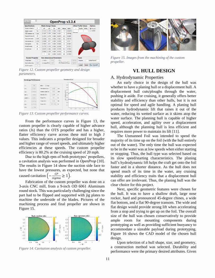
Fabrication of the custom propeller was done on a
3-axis CNC mill, from a 9-inch OD 6061 Aluminum
round stock. This was particularly challenging since the
part had to be flipped and supported with jig plates to
machine the underside of the blades. Pictures of the
machining process and final propeller are shown in
Figure 15.
Figure 14. Cavitation analysis of custom propeller.
Figure 15. Images from the machining of the custom
propeller.
VI. HULL DESIGN
A. Hydrodynamic Properties An early choice in the design of the hull was
whether to have a planing hull or a displacement hull. A
displacement hull cuts/ploughs through the water,
pushing it aside. For cruising, it generally offers better
stability and efficiency than other hulls, but it is not
optimal for speed and agile handling. A planing hull
produces hydrodynamic lift that raises it out of the
water, reducing its wetted surface as it skims atop the
water surface. The planning hull is capable of higher
speed, acceleration, and agility over a displacement
hull, although the planning hull is less efficient and
requires more power to maintain its lift [11].
The Unmanned Foil was intended to spend the
majority of its time up on the foil (with the hull entirely
out of the water). The only time the hull was expected
to be in the water was at low speeds when either starting
or stopping. Thus, the hull type was selected based on
its slow speed/starting characteristics. The planing
hull’s hydrodynamic lift helps the craft get onto the foil
faster and in a shorter distance. As the hull does not
spend much of its time in the water, any cruising
stability and efficiency traits that a displacement hull
can offer are irrelevant. Thus, the planing hull was the
clear choice for this project.
Next, specific geometric features were chosen for
the hull. It was to have a shallow draft, large nose
rocker, hard and pronounced 45-degree chines, a wide
flat bottom, and a flat 90-degree transom. The wide and
flat design would provide strong lift when accelerating
from a stop and trying to get up on the foil. The overall
size of the hull was chosen conservatively to provide
ample room for mounting components during
prototyping as well as providing sufficient buoyancy to
accommodate a sizeable payload during prototyping.
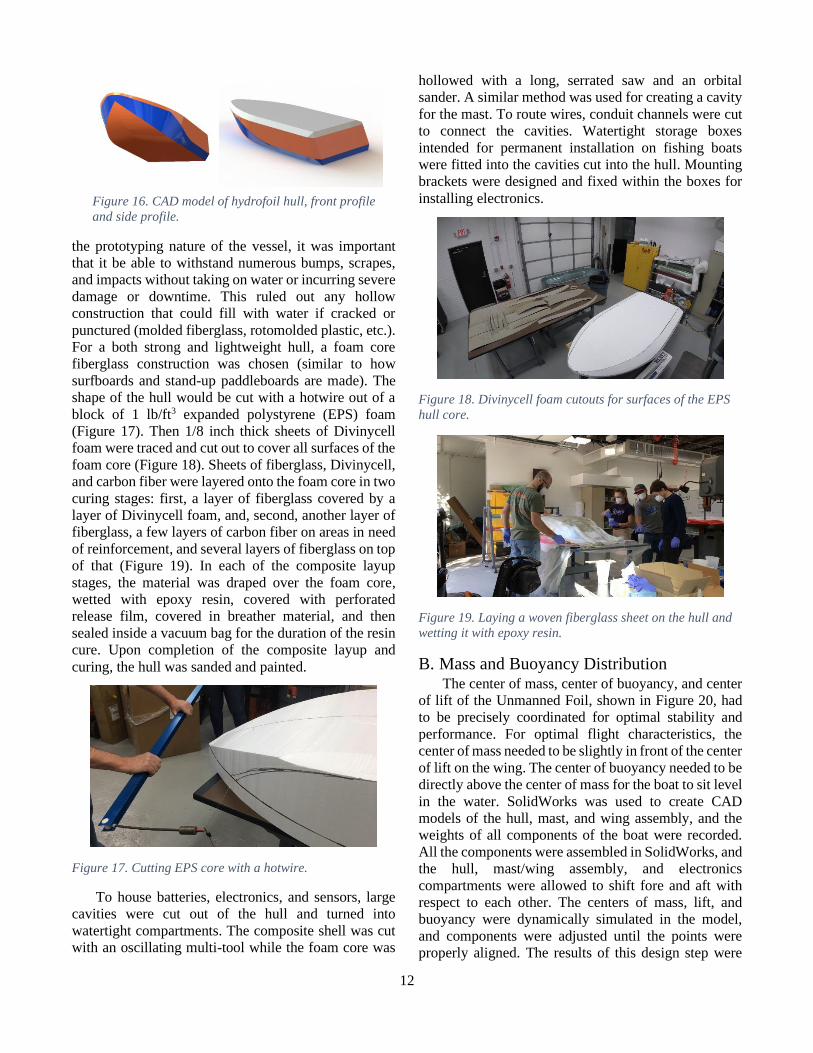
Figure 16 shows the CAD model of the chosen hull
design.
Upon selection of a hull shape, size, and geometry,
a construction method was selected. Durability and
performance were the primary desired attributes. Given
12
the prototyping nature of the vessel, it was important
that it be able to withstand numerous bumps, scrapes,
and impacts without taking on water or incurring severe
damage or downtime. This ruled out any hollow
construction that could fill with water if cracked or
punctured (molded fiberglass, rotomolded plastic, etc.).
For a both strong and lightweight hull, a foam core
fiberglass construction was chosen (similar to how
surfboards and stand-up paddleboards are made). The
shape of the hull would be cut with a hotwire out of a
block of 1 lb/ft3 expanded polystyrene (EPS) foam
(Figure 17). Then 1/8 inch thick sheets of Divinycell
foam were traced and cut out to cover all surfaces of the
foam core (Figure 18). Sheets of fiberglass, Divinycell,
and carbon fiber were layered onto the foam core in two
curing stages: first, a layer of fiberglass covered by a
layer of Divinycell foam, and, second, another layer of
fiberglass, a few layers of carbon fiber on areas in need
of reinforcement, and several layers of fiberglass on top
of that (Figure 19). In each of the composite layup
stages, the material was draped over the foam core,
wetted with epoxy resin, covered with perforated
release film, covered in breather material, and then
sealed inside a vacuum bag for the duration of the resin
cure. Upon completion of the composite layup and
curing, the hull was sanded and painted.
Figure 17. Cutting EPS core with a hotwire.
To house batteries, electronics, and sensors, large
cavities were cut out of the hull and turned into
watertight compartments. The composite shell was cut
with an oscillating multi-tool while the foam core was
hollowed with a long, serrated saw and an orbital
sander. A similar method was used for creating a cavity
for the mast. To route wires, conduit channels were cut
to connect the cavities. Watertight storage boxes
intended for permanent installation on fishing boats
were fitted into the cavities cut into the hull. Mounting
brackets were designed and fixed within the boxes for
installing electronics.
Figure 18. Divinycell foam cutouts for surfaces of the EPS
hull core.
Figure 19. Laying a woven fiberglass sheet on the hull and
wetting it with epoxy resin.
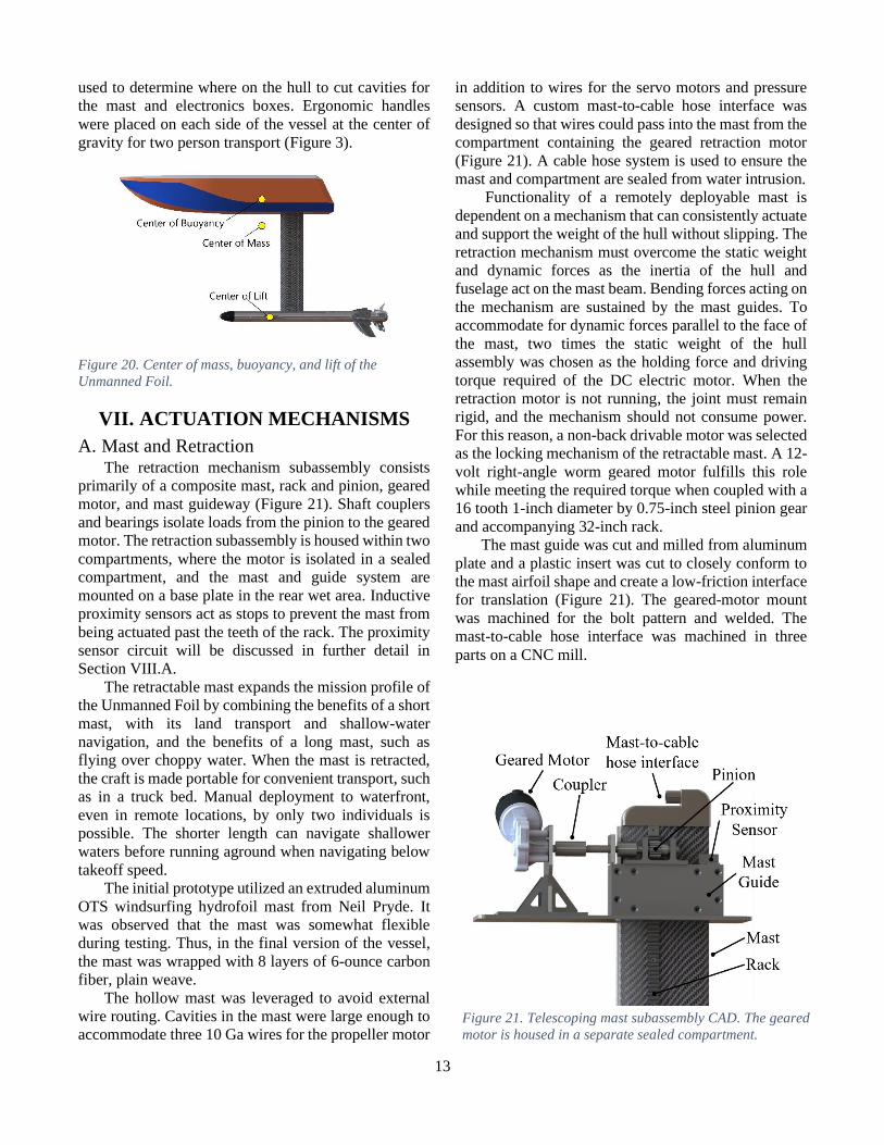
B. Mass and Buoyancy Distribution The center of mass, center of buoyancy, and center
of lift of the Unmanned Foil, shown in Figure 20, had
to be precisely coordinated for optimal stability and
performance. For optimal flight characteristics, the
center of mass needed to be slightly in front of the center
of lift on the wing. The center of buoyancy needed to be
directly above the center of mass for the boat to sit level
in the water. SolidWorks was used to create CAD
models of the hull, mast, and wing assembly, and the
weights of all components of the boat were recorded.
All the components were assembled in SolidWorks, and
the hull, mast/wing assembly, and electronics
compartments were allowed to shift fore and aft with
respect to each other. The centers of mass, lift, and
buoyancy were dynamically simulated in the model,
and components were adjusted until the points were
properly aligned. The results of this design step were
Figure 16. CAD model of hydrofoil hull, front profile
and side profile.
13
used to determine where on the hull to cut cavities for
the mast and electronics boxes. Ergonomic handles
were placed on each side of the vessel at the center of
gravity for two person transport (Figure 3).
Figure 20. Center of mass, buoyancy, and lift of the
Unmanned Foil.
VII. ACTUATION MECHANISMS
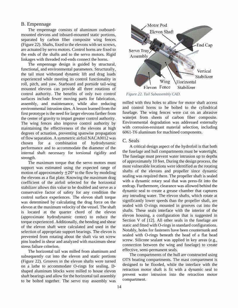
A. Mast and Retraction The retraction mechanism subassembly consists
primarily of a composite mast, rack and pinion, geared
motor, and mast guideway (Figure 21). Shaft couplers
and bearings isolate loads from the pinion to the geared
motor. The retraction subassembly is housed within two
compartments, where the motor is isolated in a sealed
compartment, and the mast and guide system are
mounted on a base plate in the rear wet area. Inductive
proximity sensors act as stops to prevent the mast from
being actuated past the teeth of the rack. The proximity
sensor circuit will be discussed in further detail in
Section VIII.A.
The retractable mast expands the mission profile of
the Unmanned Foil by combining the benefits of a short
mast, with its land transport and shallow-water
navigation, and the benefits of a long mast, such as
flying over choppy water. When the mast is retracted,
the craft is made portable for convenient transport, such
as in a truck bed. Manual deployment to waterfront,
even in remote locations, by only two individuals is
possible. The shorter length can navigate shallower
waters before running aground when navigating below
takeoff speed.
The initial prototype utilized an extruded aluminum
OTS windsurfing hydrofoil mast from Neil Pryde. It
was observed that the mast was somewhat flexible
during testing. Thus, in the final version of the vessel,
the mast was wrapped with 8 layers of 6-ounce carbon
fiber, plain weave.
The hollow mast was leveraged to avoid external
wire routing. Cavities in the mast were large enough to
accommodate three 10 Ga wires for the propeller motor
in addition to wires for the servo motors and pressure
sensors. A custom mast-to-cable hose interface was
designed so that wires could pass into the mast from the
compartment containing the geared retraction motor
(Figure 21). A cable hose system is used to ensure the
mast and compartment are sealed from water intrusion.
Functionality of a remotely deployable mast is
dependent on a mechanism that can consistently actuate
and support the weight of the hull without slipping. The
retraction mechanism must overcome the static weight
and dynamic forces as the inertia of the hull and
fuselage act on the mast beam. Bending forces acting on
the mechanism are sustained by the mast guides. To
accommodate for dynamic forces parallel to the face of
the mast, two times the static weight of the hull
assembly was chosen as the holding force and driving
torque required of the DC electric motor. When the
retraction motor is not running, the joint must remain
rigid, and the mechanism should not consume power.
For this reason, a non-back drivable motor was selected
as the locking mechanism of the retractable mast. A 12-
volt right-angle worm geared motor fulfills this role
while meeting the required torque when coupled with a
16 tooth 1-inch diameter by 0.75-inch steel pinion gear
and accompanying 32-inch rack.
The mast guide was cut and milled from aluminum
plate and a plastic insert was cut to closely conform to
the mast airfoil shape and create a low-friction interface
for translation (Figure 21). The geared-motor mount
was machined for the bolt pattern and welded. The
mast-to-cable hose interface was machined in three
parts on a CNC mill.
Figure 21. Telescoping mast subassembly CAD. The geared
motor is housed in a separate sealed compartment.
14
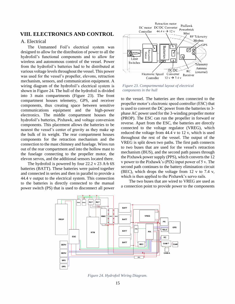
B. Empennage The empennage consists of aluminum outboard-
mounted elevons and inboard-mounted static portions,
separated by carbon fiber composite wing fences
(Figure 22). Shafts, fixed to the elevons with set screws,
are actuated by servo motors. Control horns are fixed to
the ends of the shafts and to the servo motors. Rigid
linkages with threaded rod-ends connect the horns.
The empennage design is guided by structural,
functional, and environmental parameters. Structurally,
the tail must withstand dynamic lift and drag loads
experienced while meeting its control functionality in
roll, pitch, and yaw. Starboard and portside tail-wing
mounted elevons can provide all three rotations of
control authority. The benefits of only two control
surfaces include fewer moving parts for fabrication,
assembly, and maintenance, while also reducing
environmental intrusion sites. A lesson learned from the
first prototype is the need for larger elevons farther from
the center of gravity to impart greater control authority.
The wing fences also improve control authority by
maintaining the effectiveness of the elevons at high
degrees of actuation, preventing spanwise propagation
of flow separation. A symmetric airfoil NACA0012 was
chosen for a combination of hydrodynamic
performance and to accommodate the diameter of the
internal shaft necessary for torsional rigidity and
strength.
The maximum torque that the servo motors must
support was estimated using the expected range of
motion of approximately ±20° to the flow by modeling
the elevons as a flat plate. Knowing the maximum drag
coefficient of the airfoil selected for the horizontal
stabilizer allows this value to be doubled and serve as a
conservative factor of safety for any condition the
control surface experiences. The elevon shaft torque
was determined by calculating the drag force on the
elevon at the maximum velocity of the vessel. The shaft
is located at the quarter chord of the elevon
(approximate hydrodynamic center) to reduce the
torque experienced. Additionally, the bending and shear
of the elevon shaft were calculated and used in the
selection of appropriate support bearings. The elevon is
prevented from rotating about the shaft via set screw
pins loaded in shear and analyzed with maximum shear
stress failure criterion.
The horizontal tail was milled from aluminum and
subsequently cut into the elevon and static portions
(Figure 22). Grooves in the elevon shafts were turned
on a lathe to accommodate O-rings for sealing. D-
shaped aluminum blocks were milled to house elevon
shaft bearings and allow for the horizontal tail assembly
to be bolted together. The servo tray assembly was
milled with thru holes to allow for motor shaft access
and control horns to be bolted to the cylindrical
fuselage. The wing fences were cut on an abrasive
waterjet from sheets of carbon fiber composite.
Environmental degradation was addressed externally
with corrosion-resistant material selection, including
6061-T6 aluminum for machined components.
C. Seals A critical design aspect of the hydrofoil is that both
the fuselage and hull compartments must be watertight.
The fuselage must prevent water intrusion up to depths
of approximately 10 feet. During the design process, the
most vulnerable locations were identified as the rotating
shafts of the elevons and propeller since dynamic
sealing was required there. The propeller shaft is sealed
with a dynamic rotary seal that was press-fit into the
endcap. Furthermore, clearance was allowed behind the
dynamic seal to create a grease chamber that captures
any intruding water. The elevon shafts, which rotate at
significantly lower speeds than the propeller shaft, are
sealed with O-rings mounted in grooves cut into the
shafts. These seals interface with the interior of the
elevon housing, a configuration that is suggested in
Section V of [12]. All other seals in the fuselage are
static and fitted with O-rings in standard configurations.
Notably, holes for fasteners have been countersunk and
sealed with O-rings beneath the head of a flat head
screw. Silicone sealant was applied in key areas (e.g.,
connection between the wing and fuselage) to create
effective, semi-permanent seals.
The compartments of the hull are constructed using
OTS boating compartments. The mast compartment is
designed to be flooded, while the interface with the
retraction motor shaft is fit with a dynamic seal to
prevent water intrusion into the retraction motor
compartment.
Figure 22. Tail Subassembly CAD.
15
VIII. ELECTRONICS AND CONTROL
A. Electrical The Unmanned Foil’s electrical system was
designed to allow for the distribution of power to all the
hydrofoil’s functional components and to allow for
wireless and autonomous control of the vessel. Power
from the hydrofoil’s batteries had to be distributed at
various voltage levels throughout the vessel. This power
was used for the vessel’s propeller, elevons, retraction
mechanism, sensors, and communication equipment. A
wiring diagram of the hydrofoil’s electrical system is
shown in Figure 24. The hull of the hydrofoil is divided
into 3 main compartments (Figure 23). The front
compartment houses telemetry, GPS, and receiver
components, thus creating space between sensitive
communications equipment and the high-power
electronics. The middle compartment houses the
hydrofoil’s batteries, Pixhawk, and voltage conversion
components. This placement allows the batteries to be
nearest the vessel’s center of gravity as they make up
the bulk of its weight. The rear compartment houses
components for the retraction mechanism and the
connection to the mast chimney and fuselage. Wires run
out of the rear compartment and into the hollow mast to
the fuselage connecting to the propeller motor, the
elevon servos, and the additional sensors located there.
The hydrofoil is powered by four 22.2 v 23 A∙h 6S
batteries (BATT). These batteries were paired together
and connected in series and then in parallel to provide a
44.4 v output to the electrical system. This connection
to the batteries is directly connected to the manual
power switch (PS) that is used to disconnect all power
to the vessel. The batteries are then connected to the
propeller motor’s electronic speed controller (ESC) that
is used to convert the DC power from the batteries to 3-
phase AC power used for the 3-winding propeller motor
(PROP). The ESC can run the propeller in forward or
reverse. Apart from the ESC, the batteries are directly
connected to the voltage regulator (VREG), which
reduced the voltage from 44.4 v to 12 v, which is used
throughout the rest of the vessel. The output of the
VREG is split down two paths. The first path connects
to two buses that are used for the vessel's retraction
mechanism (BUS), and the second path passes through
the Pixhawk power supply (PPS), which converts the 12
v power to the Pixhawk’s (PIX) input power of 5 v. The
second path continues to the battery elimination circuit
(BEC), which drops the voltage from 12 v to 7.4 v,
which is then applied to the Pixhawk’s servo rails.
The two buses that are wired to VREG are used as
a connection point to provide power to the components
Figure 24. Hydrofoil Wiring Diagram.
Figure 23. Compartmental layout of electrical
components in the hull
16
that control the retraction mechanism motor (RTM).
The buses connect to the retraction motor controller
(RMC), which has outputs connected to two single pole
double throw (SPDT) relays (RLY). These relays were
controlled by the RMC and two proximity sensors
(PROX) that were activated by inserts at the top and
bottom of the mast of the hydrofoil. The activation of
the relays controls the direction of the RTM, which then
lowers or raises the mast. The relays’ default state
connects the terminals of the motor (which are
connected to the relay’s common terminals) to the
RMC, which are connected to the normally closed
terminals of the relays. When the RMC directs power to
one relay or the other, the motor can run in forward or
reverse. The proximity sensors that are connected to the
coils of the relays are activated when inserts at the
bottom or top of the hydrofoil’s mast come into
proximity with the face of the sensor. When the sensor
is activated it closes a switch that allows power to flow
through the coil of the relay. This switches one of the
relays from its normally closed position to its open
position disconnecting one of the motor terminals from
the RMC and preventing the motor from running. These
proximity sensors prevent the retraction mechanism
from being raised or lowered outside of a desired range
while still allowing the mechanism to be directed in the
opposite direction from where it was stopped. The Pixhawk 2.1 is the main hub for the hydrofoil’s
electrical system. It allows for control of the propeller,
elevons, and retraction mechanism, and has the
capability to process signals from telemetry equipment
and sensors to allow for wireless manual control of the
vessel as well as autonomous control through software
installed on the Pixhawk. The Pixhawk has a built-in
IMU comprised of a 3-axis gyro, accelerometer, and
magnetometer. The IMU is used extensively with the
Pixhawk’s fly-by-wire functionality that automatically
stabilizes the vessel when flown manually or
autonomously. The Pixhawk is additionally connected
to a global positioning system (GPS), a remote-control
transmitter (RC), and a telemetry receiver (TELE),
which are used to manually control the vessel, send and
receive data, and follow predetermined paths
autonomously. The servo rails allow for the Pixhawk to
provide power and control signals to and receive and
record data from the hydrofoil’s components.
Connected to the servo rails are the speed pressure
sensor (SPS) and depth pressure sensor (DPS), which
are used to control the speed and height of the hydrofoil
during flight. The servo rails also connect to the elevons
(SERV), which are used to steer the hydrofoil during
flight. The servo rails power the camera (CAM) and
transmitter (CAM T) that allow the hydrofoil to record
and transmit live footage. Lastly, the servo rails connect
to the ESC and RMC to send control signals to the
propeller motor and retraction mechanism motor.
B. Autopilot Hardware/Software As described in the previous section, the Unmanned
Foil is equipped with an electronic hardware package
that allows it to be controlled remotely and, to some
extent, autonomously. The two pressure sensors,
installed in the fuselage of the vessel, measure depth
and water-speed, which is critical to the subsequently
discussed height control loop. The pilot can send
commands to the vessel via a telemetry connection or
through a long-range RC transmitter, which permits
high latency manual control of the vessel. The telemetry
modem is connected to a mission computer that runs a
program called Mission Planner, which is used to plan
autonomous missions and modify parameters in the
autopilot software.
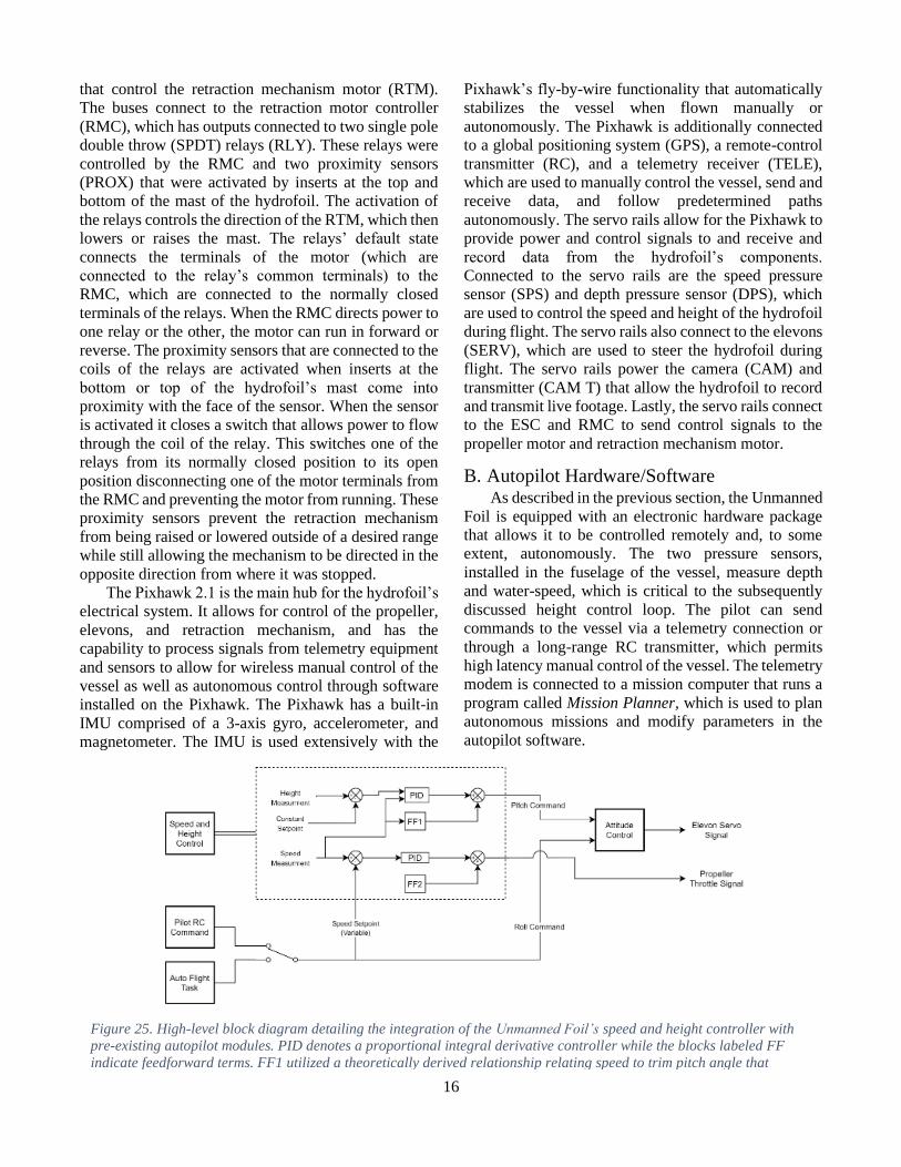
Figure 25. High-level block diagram detailing the integration of the Unmanned Foil’s speed and height controller with
pre-existing autopilot modules. PID denotes a proportional integral derivative controller while the blocks labeled FF
indicate feedforward terms. FF1 utilized a theoretically derived relationship relating speed to trim pitch angle that
scaled. proportional to 1/(𝑉𝑒𝑙𝑜𝑐𝑖𝑡𝑦)2. FF2 was an experimentally derived linear affine fit relating throttle to steady
17
The software running on the Pixhawk autopilot is a
customized version of the open source ArduPlane
library [13]. ArduPlane, a subclass of the larger
ArduPilot repository, is a versatile software package
that is intended for the control of small to mid-scale
fixed-wing drones. The package has a diverse library of
sensor drivers, safety and logging features, and features
that allow drones to be flown remotely. Towards the
latter end, a hierarchy of flight modes let the pilot
interact with the vessel with increasing degrees of
autonomy. These modes include Manual, where no
autopilot assistance is provided; Fly By Wire A
(FBWA), which stabilizes the roll axis while the pilot
controls pitch and throttle; and Auto mode, which is a
completely hands off mode where the vessel conducts a
mission that has been pre-programmed using Mission
Planner.
While the stock ArduPlane software was, in many
ways, applicable for the hydrofoil project, it was
necessary to rework some key features. The primary
alteration was the development of a speed and height
control loop that uses measurements from the onboard
pressure sensors as feedback. This new controller
replaces the total energy speed and height control
(TECS) system. Operational requirements of the
hydrofoil necessitate that the vessel can travel for long
periods of time at a constant velocity and a fixed height.
The TECS is based on a typical fixed-wing control
strategy, which is to change the pitch of the aircraft to
gain speed. Initial testing showed that the TECS was
ineffective for precision height holding with the
hydrofoil, and thus the new controller was designed to
decouple pitch and speed in the control loop.
Figure 25 gives a high-level overview of the new
speed and height controller. The height controller
regulates the depth of the fuselage, related to the height
of the hull through the fully extended mast length, to a
user-defined setpoint by commanding a pitch angle.
Gain scaling and a feedforward trim term are used to
improve performance and account for the velocity-
dependent lift force. A low-level control loop converts
the pitch demand to a signal for the elevons of the
vessel. Meanwhile, the speed controller drives the
measured water-speed to a setpoint defined by the
position of a joystick on the RC transmitter. The speed
controller used an experimentally derived feedforward
term that was obtained by fitting a curve to steady-state
water-speed data gathered at various fixed throttle
settings.
IX. TESTING Testing of the Unmanned Foil was conducted at
Lake Wauburg in Gainesville, Florida, under
permission from the University of Florida. Numerous
cycles of testing were conducted to iteratively improve
the hydrofoil control software and evaluate the
robustness of the mechanical design. Trials were
conducted at high speeds using the smaller set of wings,
while slow speed testing was done with the large set of
wings.
Control gains for the speed, height, and attitude
controllers were iteratively tuned in the field. Since
crashes of the vessel into the water were benign, this
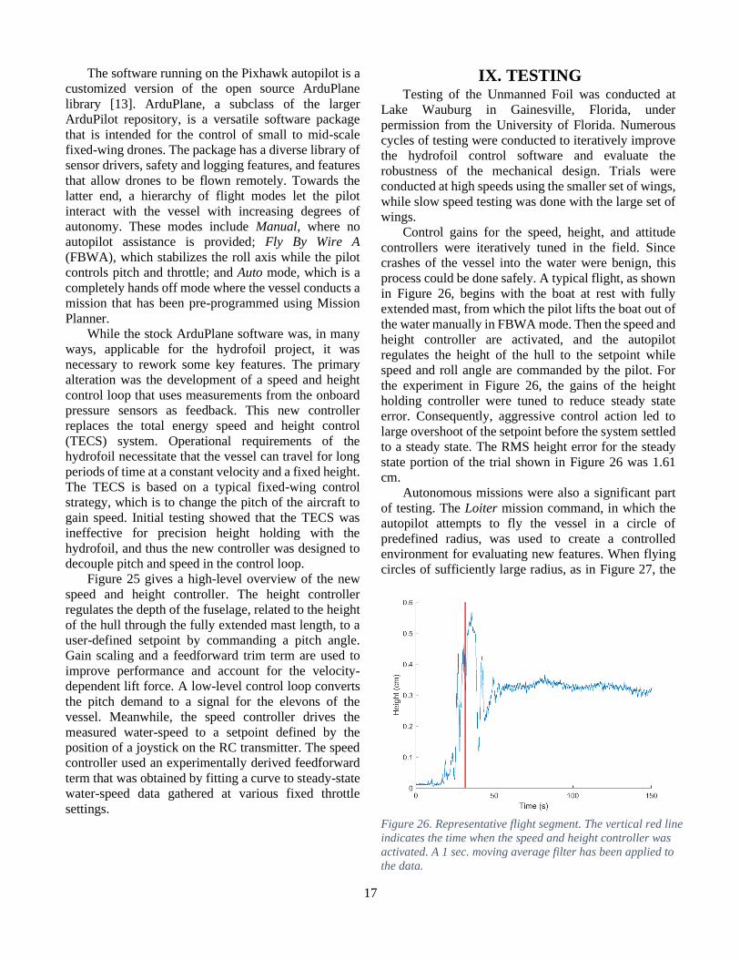
process could be done safely. A typical flight, as shown
in Figure 26, begins with the boat at rest with fully
extended mast, from which the pilot lifts the boat out of
the water manually in FBWA mode. Then the speed and
height controller are activated, and the autopilot
regulates the height of the hull to the setpoint while
speed and roll angle are commanded by the pilot. For
the experiment in Figure 26, the gains of the height
holding controller were tuned to reduce steady state
error. Consequently, aggressive control action led to
large overshoot of the setpoint before the system settled
to a steady state. The RMS height error for the steady
state portion of the trial shown in Figure 26 was 1.61
cm.
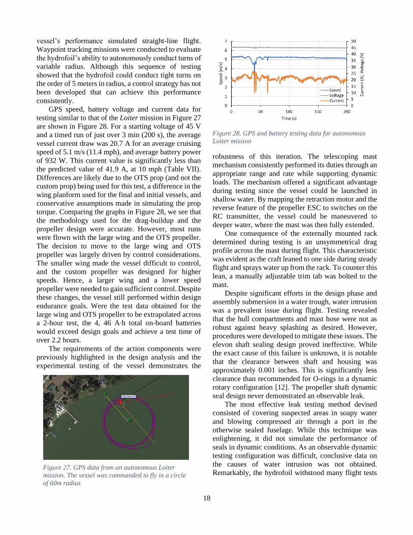
Autonomous missions were also a significant part
of testing. The Loiter mission command, in which the
autopilot attempts to fly the vessel in a circle of
predefined radius, was used to create a controlled
environment for evaluating new features. When flying
circles of sufficiently large radius, as in Figure 27, the
Figure 26. Representative flight segment. The vertical red line
indicates the time when the speed and height controller was
activated. A 1 sec. moving average filter has been applied to
the data.
18
vessel’s performance simulated straight-line flight.
Waypoint tracking missions were conducted to evaluate
the hydrofoil’s ability to autonomously conduct turns of
variable radius. Although this sequence of testing
showed that the hydrofoil could conduct tight turns on
the order of 5 meters in radius, a control strategy has not
been developed that can achieve this performance
consistently.
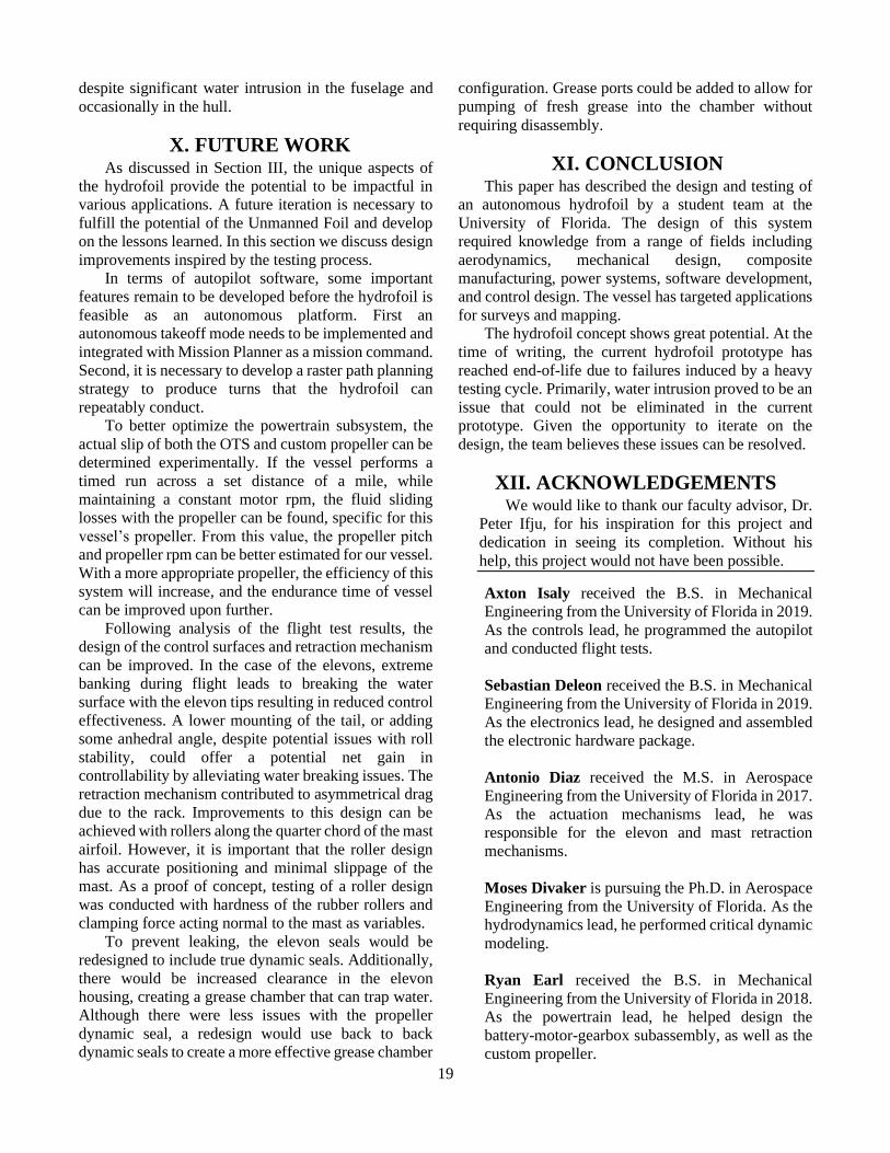
GPS speed, battery voltage and current data for
testing similar to that of the Loiter mission in Figure 27
are shown in Figure 28. For a starting voltage of 45 V
and a timed run of just over 3 min (200 s), the average
vessel current draw was 20.7 A for an average cruising
speed of 5.1 m/s (11.4 mph), and average battery power
of 932 W. This current value is significantly less than
the predicted value of 41.9 A, at 10 mph (Table VII).
Differences are likely due to the OTS prop (and not the
custom prop) being used for this test, a difference in the
wing planform used for the final and initial vessels, and
conservative assumptions made in simulating the prop
torque. Comparing the graphs in Figure 28, we see that
the methodology used for the drag-buildup and the
propeller design were accurate. However, most runs
were flown with the large wing and the OTS propeller.
The decision to move to the large wing and OTS
propeller was largely driven by control considerations.
The smaller wing made the vessel difficult to control,
and the custom propeller was designed for higher
speeds. Hence, a larger wing and a lower speed
propeller were needed to gain sufficient control. Despite
these changes, the vessel still performed within design
endurance goals. Were the test data obtained for the
large wing and OTS propeller to be extrapolated across
a 2-hour test, the 4, 46 A∙h total on-board batteries
would exceed design goals and achieve a test time of
over 2.2 hours.
The requirements of the action components were
previously highlighted in the design analysis and the
experimental testing of the vessel demonstrates the
robustness of this iteration. The telescoping mast
mechanism consistently performed its duties through an
appropriate range and rate while supporting dynamic
loads. The mechanism offered a significant advantage
during testing since the vessel could be launched in
shallow water. By mapping the retraction motor and the
reverse feature of the propeller ESC to switches on the
RC transmitter, the vessel could be maneuvered to
deeper water, where the mast was then fully extended.
One consequence of the externally mounted rack
determined during testing is an unsymmetrical drag
profile across the mast during flight. This characteristic
was evident as the craft leaned to one side during steady
flight and sprays water up from the rack. To counter this
lean, a manually adjustable trim tab was bolted to the
mast.
Despite significant efforts in the design phase and
assembly submersion in a water trough, water intrusion
was a prevalent issue during flight. Testing revealed
that the hull compartments and mast hose were not as
robust against heavy splashing as desired. However,
procedures were developed to mitigate these issues. The
elevon shaft sealing design proved ineffective. While
the exact cause of this failure is unknown, it is notable
that the clearance between shaft and housing was
approximately 0.001 inches. This is significantly less
clearance than recommended for O-rings in a dynamic
rotary configuration [12]. The propeller shaft dynamic
seal design never demonstrated an observable leak.
The most effective leak testing method devised
consisted of covering suspected areas in soapy water
and blowing compressed air through a port in the
otherwise sealed fuselage. While this technique was
enlightening, it did not simulate the performance of
seals in dynamic conditions. As an observable dynamic
testing configuration was difficult, conclusive data on
the causes of water intrusion was not obtained.
Remarkably, the hydrofoil withstood many flight tests Figure 27. GPS data from an autonomous Loiter
mission. The vessel was commanded to fly in a circle
of 60m radius
Figure 28. GPS and battery testing data for autonomous
Loiter mission
19
despite significant water intrusion in the fuselage and
occasionally in the hull.
X. FUTURE WORK As discussed in Section III, the unique aspects of
the hydrofoil provide the potential to be impactful in
various applications. A future iteration is necessary to
fulfill the potential of the Unmanned Foil and develop
on the lessons learned. In this section we discuss design
improvements inspired by the testing process.
In terms of autopilot software, some important
features remain to be developed before the hydrofoil is
feasible as an autonomous platform. First an
autonomous takeoff mode needs to be implemented and
integrated with Mission Planner as a mission command.
Second, it is necessary to develop a raster path planning
strategy to produce turns that the hydrofoil can
repeatably conduct.
To better optimize the powertrain subsystem, the
actual slip of both the OTS and custom propeller can be
determined experimentally. If the vessel performs a
timed run across a set distance of a mile, while
maintaining a constant motor rpm, the fluid sliding
losses with the propeller can be found, specific for this
vessel’s propeller. From this value, the propeller pitch
and propeller rpm can be better estimated for our vessel.
With a more appropriate propeller, the efficiency of this
system will increase, and the endurance time of vessel
can be improved upon further.
Following analysis of the flight test results, the
design of the control surfaces and retraction mechanism
can be improved. In the case of the elevons, extreme
banking during flight leads to breaking the water
surface with the elevon tips resulting in reduced control
effectiveness. A lower mounting of the tail, or adding
some anhedral angle, despite potential issues with roll
stability, could offer a potential net gain in
controllability by alleviating water breaking issues. The
retraction mechanism contributed to asymmetrical drag
due to the rack. Improvements to this design can be
achieved with rollers along the quarter chord of the mast
airfoil. However, it is important that the roller design
has accurate positioning and minimal slippage of the
mast. As a proof of concept, testing of a roller design
was conducted with hardness of the rubber rollers and
clamping force acting normal to the mast as variables.
To prevent leaking, the elevon seals would be
redesigned to include true dynamic seals. Additionally,
there would be increased clearance in the elevon
housing, creating a grease chamber that can trap water.
Although there were less issues with the propeller
dynamic seal, a redesign would use back to back
dynamic seals to create a more effective grease chamber
configuration. Grease ports could be added to allow for
pumping of fresh grease into the chamber without
requiring disassembly.
XI. CONCLUSION This paper has described the design and testing of
an autonomous hydrofoil by a student team at the
University of Florida. The design of this system
required knowledge from a range of fields including
aerodynamics, mechanical design, composite
manufacturing, power systems, software development,
and control design. The vessel has targeted applications
for surveys and mapping.
The hydrofoil concept shows great potential. At the
time of writing, the current hydrofoil prototype has
reached end-of-life due to failures induced by a heavy
testing cycle. Primarily, water intrusion proved to be an
issue that could not be eliminated in the current
prototype. Given the opportunity to iterate on the
design, the team believes these issues can be resolved.
XII. ACKNOWLEDGEMENTS We would like to thank our faculty advisor, Dr.
Peter Ifju, for his inspiration for this project and
dedication in seeing its completion. Without his
help, this project would not have been possible.
Axton Isaly received the B.S. in Mechanical
Engineering from the University of Florida in 2019.
As the controls lead, he programmed the autopilot
and conducted flight tests.
Sebastian Deleon received the B.S. in Mechanical
Engineering from the University of Florida in 2019.
As the electronics lead, he designed and assembled
the electronic hardware package.
Antonio Diaz received the M.S. in Aerospace
Engineering from the University of Florida in 2017.
As the actuation mechanisms lead, he was
responsible for the elevon and mast retraction
mechanisms.
Moses Divaker is pursuing the Ph.D. in Aerospace
Engineering from the University of Florida. As the
hydrodynamics lead, he performed critical dynamic
modeling.
Ryan Earl received the B.S. in Mechanical
Engineering from the University of Florida in 2018.
As the powertrain lead, he helped design the
battery-motor-gearbox subassembly, as well as the
custom propeller.
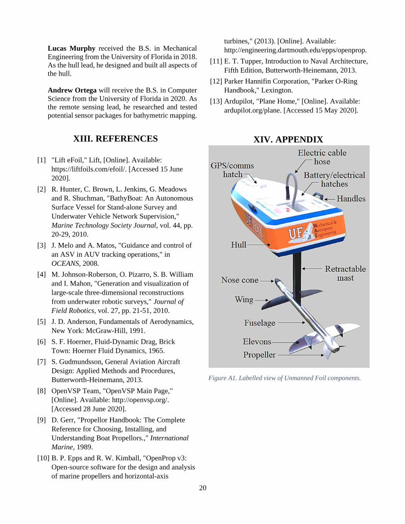
20
Lucas Murphy received the B.S. in Mechanical
Engineering from the University of Florida in 2018.
As the hull lead, he designed and built all aspects of
the hull.
Andrew Ortega will receive the B.S. in Computer
Science from the University of Florida in 2020. As
the remote sensing lead, he researched and tested
potential sensor packages for bathymetric mapping.
XIII. REFERENCES
[1] "Lift eFoil," Lift, [Online]. Available:
https://liftfoils.com/efoil/. [Accessed 15 June
2020].
[2] R. Hunter, C. Brown, L. Jenkins, G. Meadows
and R. Shuchman, "BathyBoat: An Autonomous
Surface Vessel for Stand-alone Survey and
Underwater Vehicle Network Supervision,"
Marine Technology Society Journal, vol. 44, pp.
20-29, 2010.
[3] J. Melo and A. Matos, "Guidance and control of
an ASV in AUV tracking operations," in
OCEANS, 2008.
[4] M. Johnson-Roberson, O. Pizarro, S. B. William
and I. Mahon, "Generation and visualization of
large-scale three-dimensional reconstructions
from underwater robotic surveys," Journal of
Field Robotics, vol. 27, pp. 21-51, 2010.
[5] J. D. Anderson, Fundamentals of Aerodynamics,
New York: McGraw-Hill, 1991.
[6] S. F. Hoerner, Fluid-Dynamic Drag, Brick
Town: Hoerner Fluid Dynamics, 1965.
[7] S. Gudmundsson, General Aviation Aircraft
Design: Applied Methods and Procedures,
Butterworth-Heinemann, 2013.
[8] OpenVSP Team, "OpenVSP Main Page,"
[Online]. Available: http://openvsp.org/.
[Accessed 28 June 2020].
[9] D. Gerr, "Propellor Handbook: The Complete
Reference for Choosing, Installing, and
Understanding Boat Propellors.," International
Marine, 1989.
[10] B. P. Epps and R. W. Kimball, "OpenProp v3:
Open-source software for the design and analysis
of marine propellers and horizontal-axis
turbines," (2013). [Online]. Available:
http://engineering.dartmouth.edu/epps/openprop.
[11] E. T. Tupper, Introduction to Naval Architecture,
Fifth Edition, Butterworth-Heinemann, 2013.
[12] Parker Hannifin Corporation, "Parker O-Ring
Handbook," Lexington.
[13] Ardupilot, "Plane Home," [Online]. Available:
ardupilot.org/plane. [Accessed 15 May 2020].
XIV. APPENDIX
Figure A1. Labelled view of Unmanned Foil components.