cpan-xhe3 size1 - size6
TRANSCRIPT
Installation use and maintenance manual
Make-up unit, full fresh air With return/exhaust and thermodynamic heat recovery Reversible heat pump technology
CPAN-XHE3 size1 - size6
M05G40L12-04 17-11-16

Dear Customer,
Congratulations for having chosen this product.
Clivet has been working for years to offer the market systems able to assure maxi-
mum and long-lasting wellbeing with high reliability, efficiency, quality and safety.
The company aim is that to offer its customers developed systems that assure the best
comfort, reduce energy consumptions and installation and maintenance costs for the
entire life-span of the system.
With this manual, we intend giving information useful throughout all phases: from
reception, to installation, to use and even disposal, so that such a developed system
meets the best installation and use methods.
With kind regards and... good reading!
CLIVET Spa
3
TABLE OF CONTENTS
1 Generality ......................................... 4
2 Receipt .............................................. 6
3 Positioning ....................................... 7
4 Hydraulic connections .................... 9
5 Aeraulic connections ...................... 11
6 Electric connections ....................... 13
7 Start-up ............................................ 19
8 Control ..................................... 28
9 Maintenance ................................... 39
10 Residue risks ................................... 45
11 Disposal .......................................... 46
12 Technical information ..................... 47
The data contained in this manual are not binding and can be changed by the manufacturer without prior notice.
4
1.1 General warnings
Purpose of the manual
This manual has been realised to enable a correct installation,
adjustment and maintenance of the unit.
Manual instructions
It is of fundamental importance that the manual is carefully
read.
Pay particular attention to:
PROHIBITIONS
indicate operations that cannot be carried out as they
jeopardise the machine operation or can cause personal
injuries or damage things.
WARNINGS
indicate potentially dangerous or damaging situations.
INFORMATION
indicate particularly useful information.
The manufacturing company declines every liability for any
damages, directly or indirectly, to persons or things, following
the non-compliance with these instructions.
Preserving the manual
This manual and the wiring diagram of the unit must be
carefully kept and be available to the operator for future
consultation.
Systems designing
Installation, electric, hydraulic system, etc., must be defined
by enabled designers in accordance with the current
standards.
Qualified personnel
The unit must be installed, tested and assisted by qualified
personnel having the legal requisites.
Installation
The installation must be carried out in accordance with the
local safety standards.
Electric network
Check that the features of the electrical network are conform
with the data on the unit matriculation plate, found on the
inside of the main electric control board.
Packaging
The packaging material (plastic bags, expanded polystyrene,
nails, etc.) must be kept out of the reach of children as it is a
potential source of danger and must be correctly recycled in
accordance with the local standards in force.
Maintenance
Disconnect the electric power supply to the unit before
carrying out any maintenance. The operations must be carried
out in accordance with the local safety
standards.
Periodical checks
Carry out periodical checks to identify any loose, damaged or
broken parts. The lack in repair
entails the risk of damages to things and personal injuries.
Fault – Malfunctioning
Disconnect the equipment in case of fault or
malfunctioning.
Repair
For any repairs, only contact an after-sales technical
assistance centre authorised by the manufacturer and request
the use of original spare parts. The non-compliance with the
above can jeopardise the safety of the equipment.
Modifications
Every liability is declined by the manufacturer with voiding of
the warranty in the event of electrical and/or mechanical
modifications. Tampering in general, not expressly authorised
and not respecting that reported in this manual, void the
warranty.
Destination of use
The unit must only be intended to be used for that it was
expressly conceived:
CIVIL AIR CONDITIONING
Keep to the limits foreseen in the technical schedule and in
this manual.
Any use different to that specified does not entail any kind of
commitment or obligation by the manufacturer.
Safety integration principles
The unit is designed and manufactured so as not to expose
the personal health and safety to risk.
In this regard, project solutions have been adopted act at
eliminating, where possible, the possible causes of risk or
significantly reduce the probability of the event-risk. Should it
not have been possible to intervene during designing to
prevent and/or eliminate the risk, refer to the behavioural
prescriptions reported in the residue risks section.
Data update
The continuous improvements made to the product can
determine variations to data, even without prior notice by the
manufacturer.
User training
The installer must train the user, particularly on:
Switch-on/off
Setpoint modification
Stand-by
Maintenance
What to do/not to do in case of fault.
1 - GENERALITY
!
i
5
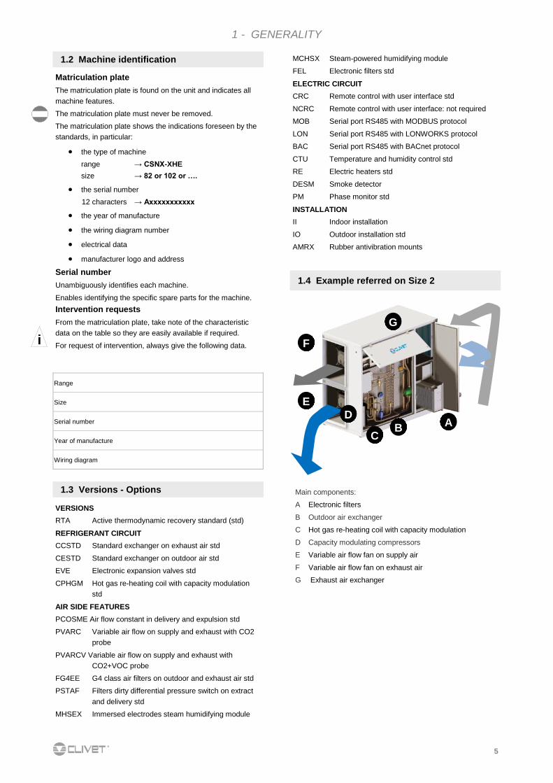
1.3 Versions - Options Main components:
A Electronic filters
B Outdoor air exchanger
C Hot gas re-heating coil with capacity modulation
D Capacity modulating compressors
E Variable air flow fan on supply air
F Variable air flow fan on exhaust air
G Exhaust air exchanger
1.4 Example referred on Size 2
A B
C
E
F
G
D
i
Matriculation plate
The matriculation plate is found on the unit and indicates all
machine features.
The matriculation plate must never be removed.
The matriculation plate shows the indications foreseen by the
standards, in particular:
the type of machine
range → CSNX-XHE
size → 82 or 102 or ….
the serial number
12 characters → Axxxxxxxxxxx
the year of manufacture
the wiring diagram number
electrical data
manufacturer logo and address
Serial number
Unambiguously identifies each machine.
Enables identifying the specific spare parts for the machine.
Intervention requests
From the matriculation plate, take note of the characteristic
data on the table so they are easily available if required.
For request of intervention, always give the following data.
Range
Size
Serial number
Year of manufacture
Wiring diagram
1.2 Machine identification
1 - GENERALITY
VERSIONS
RTA Active thermodynamic recovery standard (std)
REFRIGERANT CIRCUIT
CCSTD Standard exchanger on exhaust air std
CESTD Standard exchanger on outdoor air std
EVE Electronic expansion valves std
CPHGM Hot gas re-heating coil with capacity modulation
std
AIR SIDE FEATURES
PCOSME Air flow constant in delivery and expulsion std
PVARC Variable air flow on supply and exhaust with CO2
probe
PVARCV Variable air flow on supply and exhaust with
CO2+VOC probe
FG4EE G4 class air filters on outdoor and exhaust air std
PSTAF Filters dirty differential pressure switch on extract
and delivery std
MHSEX Immersed electrodes steam humidifying module
MCHSX Steam-powered humidifying module
FEL Electronic filters std
ELECTRIC CIRCUIT
CRC Remote control with user interface std
NCRC Remote control with user interface: not required
MOB Serial port RS485 with MODBUS protocol
LON Serial port RS485 with LONWORKS protocol
BAC Serial port RS485 with BACnet protocol
CTU Temperature and humidity control std
RE Electric heaters std
DESM Smoke detector
PM Phase monitor std
INSTALLATION
II Indoor installation
IO Outdoor installation std
AMRX Rubber antivibration mounts
6
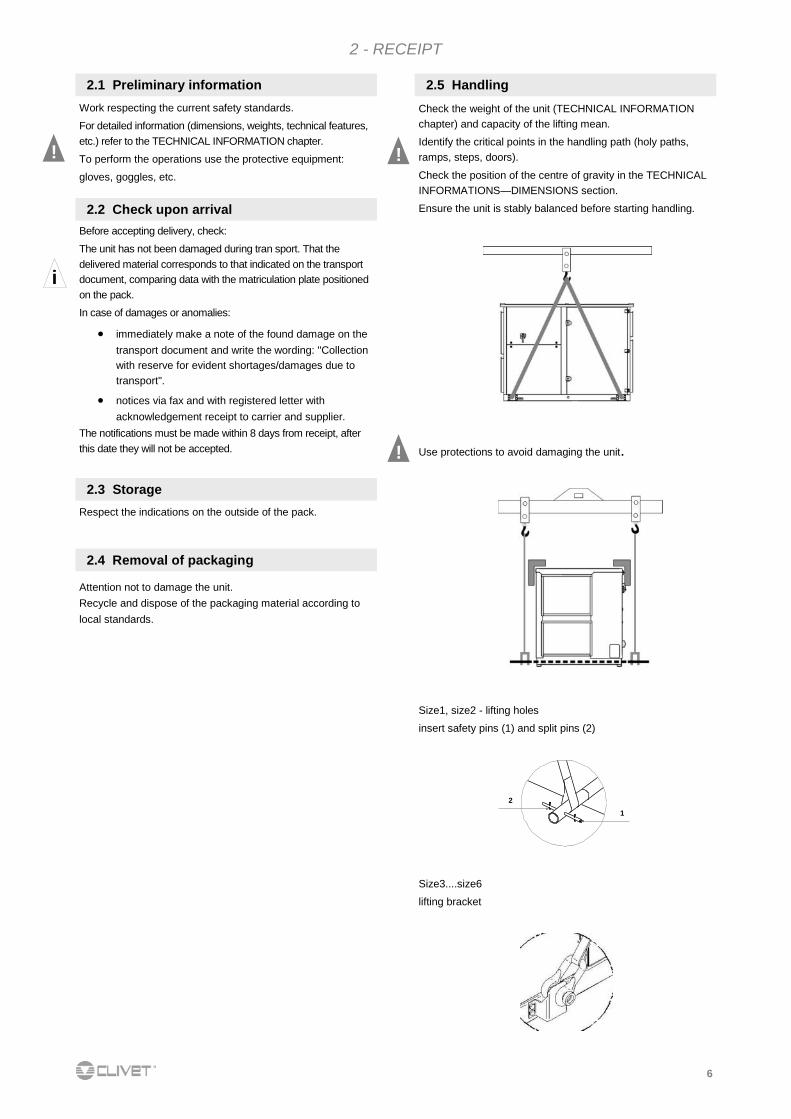
1
2
Size1, size2 - lifting holes
insert safety pins (1) and split pins (2)
Size3....size6
lifting bracket
!
Work respecting the current safety standards.
For detailed information (dimensions, weights, technical features,
etc.) refer to the TECHNICAL INFORMATION chapter.
To perform the operations use the protective equipment:
gloves, goggles, etc.
Before accepting delivery, check:
The unit has not been damaged during tran sport. That the
delivered material corresponds to that indicated on the transport
document, comparing data with the matriculation plate positioned
on the pack.
In case of damages or anomalies:
immediately make a note of the found damage on the
transport document and write the wording: "Collection
with reserve for evident shortages/damages due to
transport".
notices via fax and with registered letter with
acknowledgement receipt to carrier and supplier.
The notifications must be made within 8 days from receipt, after
this date they will not be accepted.
2.1 Preliminary information
2.2 Check upon arrival
i
Respect the indications on the outside of the pack.
2.3 Storage
2 - RECEIPT
!
Check the weight of the unit (TECHNICAL INFORMATION
chapter) and capacity of the lifting mean.
Identify the critical points in the handling path (holy paths,
ramps, steps, doors).
Check the position of the centre of gravity in the TECHNICAL
INFORMATIONS—DIMENSIONS section.
Ensure the unit is stably balanced before starting handling.
2.5 Handling
Use protections to avoid damaging the unit. !
Attention not to damage the unit.
Recycle and dispose of the packaging material according to
local standards.
2.4 Removal of packaging
7
difficulty of exchange
leaves or other bodies that can obstruct the exchange
coils
winds contrasting or favouring the air flow
heat sources near the unit (chimneys, extractors, etc.)
sources of dust or pollutants
stratification (cold air that stagnates at the bottom)
recirculation (ejected air that is taken back via suction)
positioning underneath the ground level, near very
high walls, underneath roofs or in corners (can give
rise to stratification or recirculation phenomena).
Neglecting the previous indications can lead to:
worsening of the energy efficiency.
blocks due to HIGH PRESSURE (in summer) or LOW
PRESSURE (in winter).
Avoid snow and ice accumulation in front of the external air
outlets and of the exhaust air ejection.
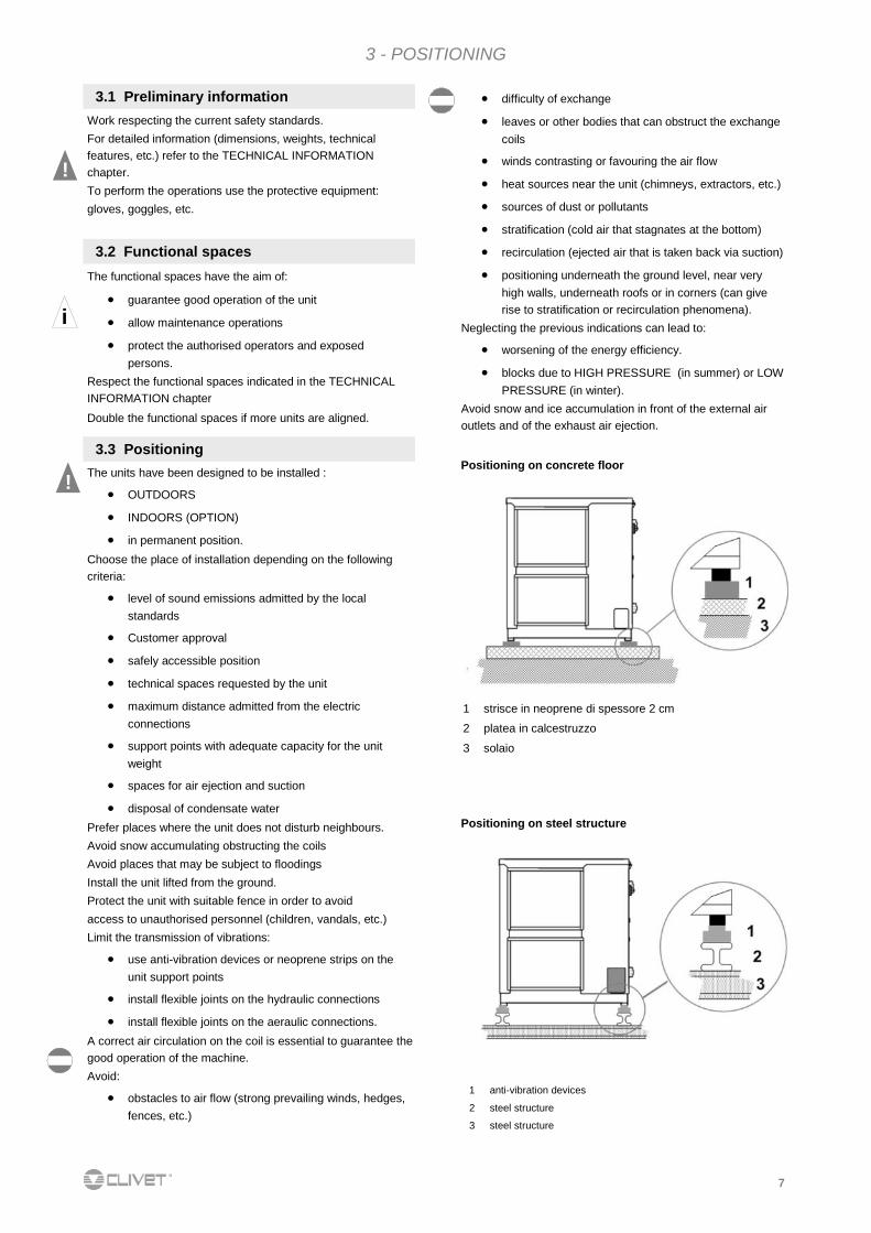
1 strisce in neoprene di spessore 2 cm
2 platea in calcestruzzo
3 solaio
3 - POSITIONING
!
i
The functional spaces have the aim of:
guarantee good operation of the unit
allow maintenance operations
protect the authorised operators and exposed
persons.
Respect the functional spaces indicated in the TECHNICAL
INFORMATION chapter
Double the functional spaces if more units are aligned.
The units have been designed to be installed :
OUTDOORS
INDOORS (OPTION)
in permanent position.
Choose the place of installation depending on the following
criteria:
level of sound emissions admitted by the local
standards
Customer approval
safely accessible position
technical spaces requested by the unit
maximum distance admitted from the electric
connections
support points with adequate capacity for the unit
weight
spaces for air ejection and suction
disposal of condensate water
Prefer places where the unit does not disturb neighbours.
Avoid snow accumulating obstructing the coils
Avoid places that may be subject to floodings
Install the unit lifted from the ground.
Protect the unit with suitable fence in order to avoid
access to unauthorised personnel (children, vandals, etc.)
Limit the transmission of vibrations:
use anti-vibration devices or neoprene strips on the
unit support points
install flexible joints on the hydraulic connections
install flexible joints on the aeraulic connections.
A correct air circulation on the coil is essential to guarantee the
good operation of the machine.
Avoid:
obstacles to air flow (strong prevailing winds, hedges,
fences, etc.)
!
Work respecting the current safety standards.
For detailed information (dimensions, weights, technical
features, etc.) refer to the TECHNICAL INFORMATION
chapter.
To perform the operations use the protective equipment:
gloves, goggles, etc.
3.1 Preliminary information
3.2 Functional spaces
3.3 Positioning Positioning on concrete floor
1 anti-vibration devices
2 steel structure
3 steel structure
Positioning on steel structure
8
3 - POSITIONING
3.4 INDOOR INSTALLATION SET-UP
3.6 STEAM HUMIDIFICATION MODULE - OPTION
Modulo di umidificazione a
vapore ad elettrodi immersi
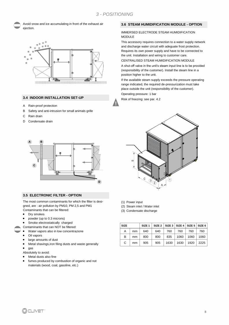
(1) Power input
(2) Steam inlet / Water inlet
(3) Condensate discharge
SIZE SIZE 1 SIZE 2 SIZE 3 SIZE 4 SIZE 5 SIZE 6
A mm 640 640 760 760 760 760
B mm 800 800 835 1060 1060 1060
C mm 905 905 1630 1630 1920 2225
IMMERSED ELECTRODE STEAM HUMIDIFICATION
MODULE
This accessory requires connection to a water supply network
and discharge water circuit with adeguate frost protection.
Requires its own power supply and have to be connected to
the unit. Installation and wiring to customer care.
CENTRALISED STEAM HUMIDIFICATION MODULE
A shut-off valve in the unit’s steam input line is to be provided
(responsibility of the customer). Install the steam line in a
position higher to the unit.
If the available steam supply exceeds the pressure operating
range indicated, the required de-pressurization must take
place outside the unit (responsibility of the customer).
Operating pressure: 1 bar
Risk of freezing: see par. 4.2
!
3.5 ELECTRONIC FILTER - OPTION
The most common contaminants for which the filter is desi-
gned, are : air pollution by PM10, PM 2,5 and PM1
Contaminants that can be filtered:
Dry smokes
powder (up to 0.3 microns)
Smoke electrostatically charged
Contaminants that can NOT be filtered:
Water vapors also in low concentrazione
Oil vapors
large amounts of dust
Metal shavings,iron filing dusts and waste generally
gas
Absolutely to avoid:
Metal dusts also fine
fumes produced by combustion of organic and not
materials (wood, coal, gasoline, etc.)
Avoid snow and ice accumulating in front of the exhaust air
ejection.
A Rain-proof protection
B Safety and anti-intrusion for small animals grille
C Rain drain
D Condensate drain
9
4.3 Hydronic recovery - option
A. vent
B. filling glycol
C. water filling tap
The device is shipped filled with water and glycol.
Adopt measures to prevent risk of freezing if the unit or
relative hydraulic connections can be subject to temperatures
near 0°C.
isolate the piping
protect the piping with heating cables laid underneath
the insulation
4.2 Risk of freezing
!
4 - HYDRAULIC CONNECTIONS
4.1 Condensate drain
The condensate must be disposed of in order to avoid
damaging things and persons.
Unit drain coupling: the connection must not transmit
mechanical stresses and must be carried out paying
attention not to damage the unit drain coupling.
Foresee a siphon that, by eliminating the depression
caused by the fan, prevents suction of air from the drain
piping.
The piping must have adequate slope to allow out flow.
Anchor the piping with an adequate number of supports.
On the contrary, cracking in the piping and air pockets
obstructing the outflow, are generated.
Isolate piping and siphon to avoid condensate dripping.
Connect the condensate drain to a rain drain network.
DO NOT use white waters or sewage drains to avoid
possible inhaling of odours in case of evaporation of the
water contained in the si phon.
At work end, check the regular outflow of the condensate
by pouring water in the bowl. i
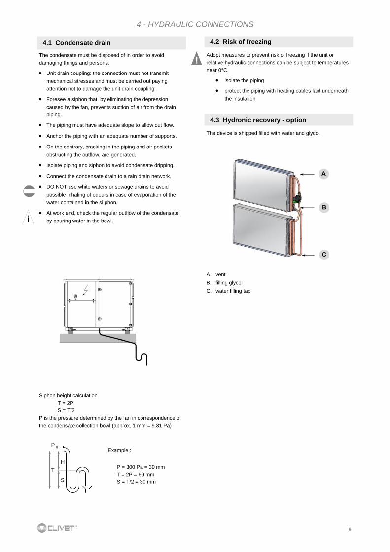
P
H
S
T
Example :
P = 300 Pa = 30 mm
T = 2P = 60 mm
S = T/2 = 30 mm
Siphon height calculation T = 2P
S = T/2
P is the pressure determined by the fan in correspondence of
the condensate collection bowl (approx. 1 mm = 9.81 Pa)
10
4 - HYDRAULIC CONNECTIONS
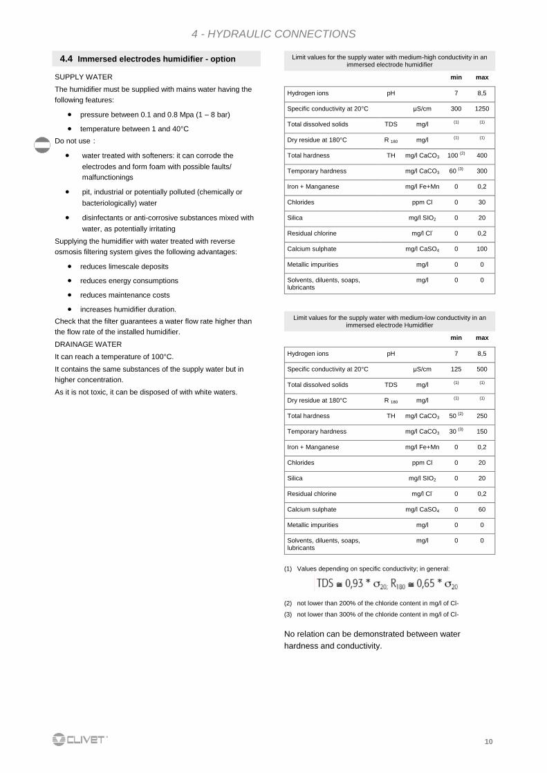
SUPPLY WATER The humidifier must be supplied with mains water having the
following features:
pressure between 0.1 and 0.8 Mpa (1 – 8 bar)
temperature between 1 and 40°C
Do not use :
water treated with softeners: it can corrode the
electrodes and form foam with possible faults/
malfunctionings
pit, industrial or potentially polluted (chemically or
bacteriologically) water
disinfectants or anti-corrosive substances mixed with
water, as potentially irritating
Supplying the humidifier with water treated with reverse
osmosis filtering system gives the following advantages:
reduces limescale deposits
reduces energy consumptions
reduces maintenance costs
increases humidifier duration.
Check that the filter guarantees a water flow rate higher than
the flow rate of the installed humidifier.
DRAINAGE WATER It can reach a temperature of 100°C.
It contains the same substances of the supply water but in
higher concentration.
As it is not toxic, it can be disposed of with white waters.
4.4 Immersed electrodes humidifier - option Limit values for the supply water with medium-high conductivity in an immersed electrode humidifier
min max
Hydrogen ions pH 7 8,5
Specific conductivity at 20°C μS/cm 300 1250
Total dissolved solids TDS mg/l (1) (1)
Dry residue at 180°C R 180 mg/l (1) (1)
Total hardness TH mg/l CaCO3 100 (2) 400
Temporary hardness mg/l CaCO3 60 (3) 300
Iron + Manganese mg/l Fe+Mn 0 0,2
Chlorides ppm Cl 0 30
Silica mg/l SIO2 0 20
Residual chlorine mg/l Cl- 0 0,2
Calcium sulphate mg/l CaSO4 0 100
Metallic impurities mg/l 0 0
Solvents, diluents, soaps, lubricants
mg/l 0 0
Limit values for the supply water with medium-low conductivity in an immersed electrode Humidifier
min max
Hydrogen ions pH 7 8,5
Specific conductivity at 20°C μS/cm 125 500
Total dissolved solids TDS mg/l (1) (1)
Dry residue at 180°C R 180 mg/l (1) (1)
Total hardness TH mg/l CaCO3 50 (2) 250
Temporary hardness mg/l CaCO3 30 (3) 150
Iron + Manganese mg/l Fe+Mn 0 0,2
Chlorides ppm Cl 0 20
Silica mg/l SIO2 0 20
Residual chlorine mg/l Cl- 0 0,2
Calcium sulphate mg/l CaSO4 0 60
Metallic impurities mg/l 0 0
Solvents, diluents, soaps, lubricants
mg/l 0 0
(1) Values depending on specific conductivity; in general:
(2) not lower than 200% of the chloride content in mg/l of Cl-
(3) not lower than 300% of the chloride content in mg/l of Cl-
No relation can be demonstrated between water
hardness and conductivity.
11
i
5 - AERAULIC CONNECTIONS
The dimensioning and correct execution of the aeraulic
connections are fundamental to guarantee good unit operation
and adequate level of silence in the room.
When designing and manufacturing the channels, consider
LOAD LOSSES, AIR FLOW AND SPEED that must be
consistent with the unit features.
Particularly consider that load losses higher than the unit
useful prevalence, lead to reduction in flow rate, with
consequent unit blocks.
the weight of the channels must not burden on the
connection flanges
place anti-vibration joints between channels and unit
connection to the flanges and between the various
sections of the channels must guarantee air seal, avoiding
dispersions penalising the overall efficiency of the system
limit the load losses by optimising the path, the type and
number of bends and junctions
use wide bends evaluating the opportunity of equipping
them with deflectors (in particular with high air speed or
bends with reduced radius).
5.1 Generality
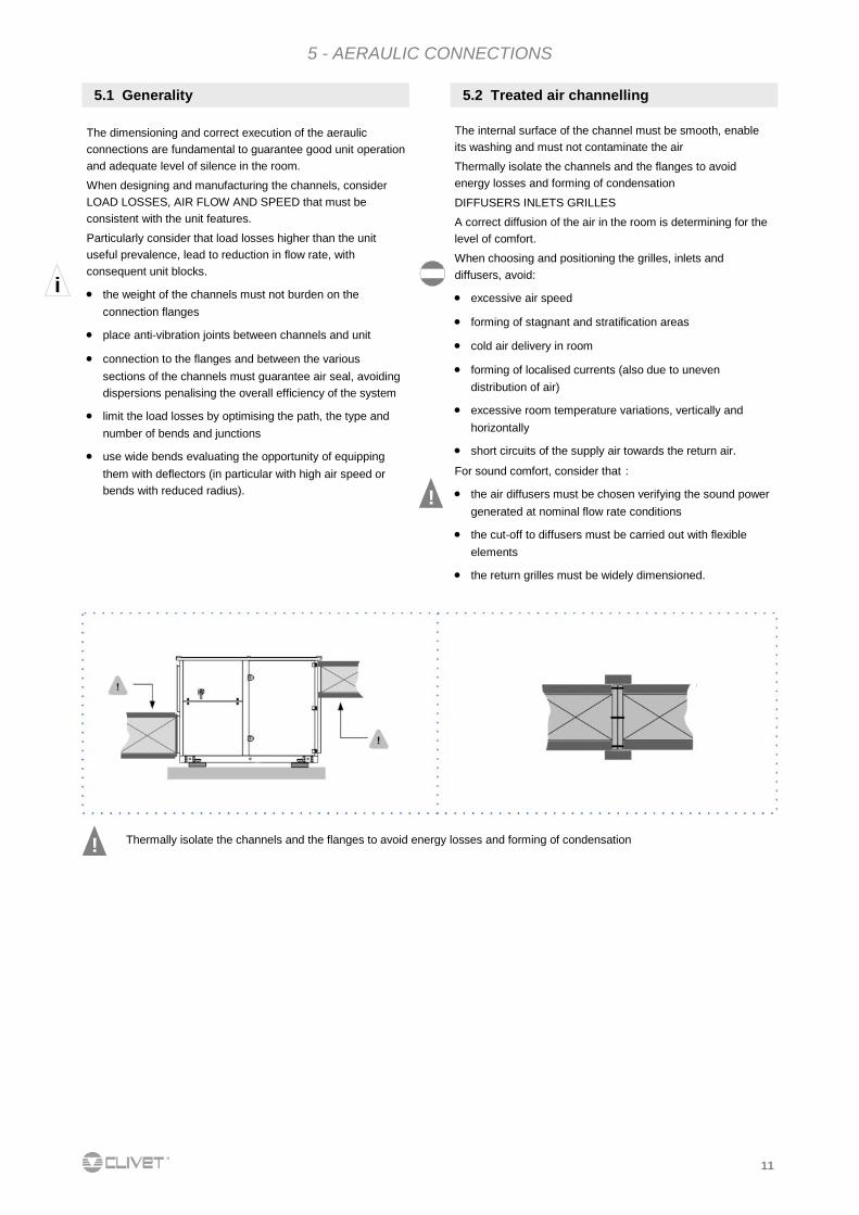
The internal surface of the channel must be smooth, enable
its washing and must not contaminate the air
Thermally isolate the channels and the flanges to avoid
energy losses and forming of condensation
DIFFUSERS INLETS GRILLES
A correct diffusion of the air in the room is determining for the
level of comfort.
When choosing and positioning the grilles, inlets and
diffusers, avoid:
excessive air speed
forming of stagnant and stratification areas
cold air delivery in room
forming of localised currents (also due to uneven
distribution of air)
excessive room temperature variations, vertically and
horizontally
short circuits of the supply air towards the return air.
For sound comfort, consider that :
the air diffusers must be chosen verifying the sound power
generated at nominal flow rate conditions
the cut-off to diffusers must be carried out with flexible
elements
the return grilles must be widely dimensioned.
5.2 Treated air channelling
!
Thermally isolate the channels and the flanges to avoid energy losses and forming of condensation !
12
5 - AERAULIC CONNECTIONS
1 2
3
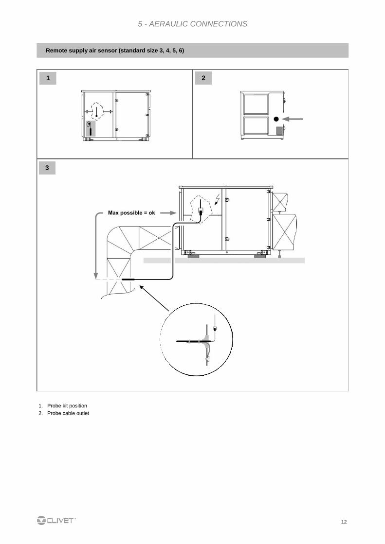
Remote supply air sensor (standard size 3, 4, 5, 6)
1. Probe kit position
2. Probe cable outlet
13
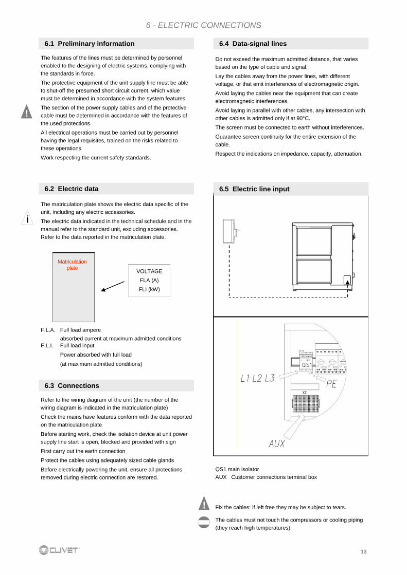
6.5 Electric line input
6.4 Data-signal lines
Do not exceed the maximum admitted distance, that varies
based on the type of cable and signal.
Lay the cables away from the power lines, with different
voltage, or that emit interferences of electromagnetic origin.
Avoid laying the cables near the equipment that can create
electromagnetic interferences.
Avoid laying in parallel with other cables, any intersection with
other cables is admitted only if at 90°C.
The screen must be connected to earth without interferences.
Guarantee screen continuity for the entire extension of the
cable.
Respect the indications on impedance, capacity, attenuation.
Fix the cables: if left free they may be subject to tears.
The cables must not touch the compressors or cooling piping
(they reach high temperatures)
!
QS1 main isolator AUX Customer connections terminal box
i
The features of the lines must be determined by personnel
enabled to the designing of electric systems, complying with
the standards in force.
The protective equipment of the unit supply line must be able
to shut-off the presumed short circuit current, which value
must be determined in accordance with the system features.
The section of the power supply cables and of the protective
cable must be determined in accordance with the features of
the used protections.
All electrical operations must be carried out by personnel
having the legal requisites, trained on the risks related to
these operations.
Work respecting the current safety standards.
6.1 Preliminary information
F.L.A. Full load ampere
absorbed current at maximum admitted conditions
F.L.I. Full load input
Power absorbed with full load
(at maximum admitted conditions)
Matriculation plate
VOLTAGE
FLA (A)
FLI (kW)
The matriculation plate shows the electric data specific of the
unit, including any electric accessories.
The electric data indicated in the technical schedule and in the
manual refer to the standard unit, excluding accessories.
Refer to the data reported in the matriculation plate.
6.2 Electric data
6.3 Connections
Refer to the wiring diagram of the unit (the number of the
wiring diagram is indicated in the matriculation plate)
Check the mains have features conform with the data reported
on the matriculation plate
Before starting work, check the isolation device at unit power
supply line start is open, blocked and provided with sign
First carry out the earth connection
Protect the cables using adequately sized cable glands
Before electrically powering the unit, ensure all protections
removed during electric connection are restored.
!
6 - ELECTRIC CONNECTIONS
14
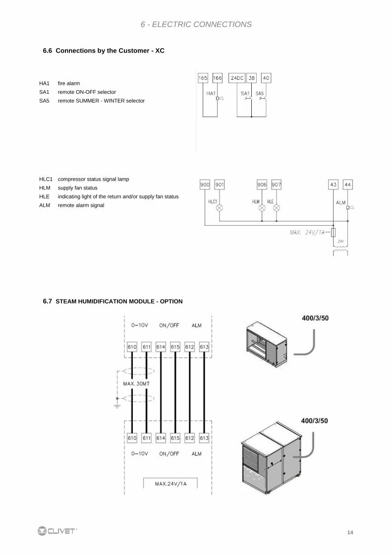
6.6 Connections by the Customer - XC
HA1 fire alarm
SA1 remote ON-OFF selector
SA5 remote SUMMER - WINTER selector
HLC1 compressor status signal lamp
HLM supply fan status
HLE indicating light of the return and/or supply fan status
ALM remote alarm signal
6.7 STEAM HUMIDIFICATION MODULE - OPTION
6 - ELECTRIC CONNECTIONS
15
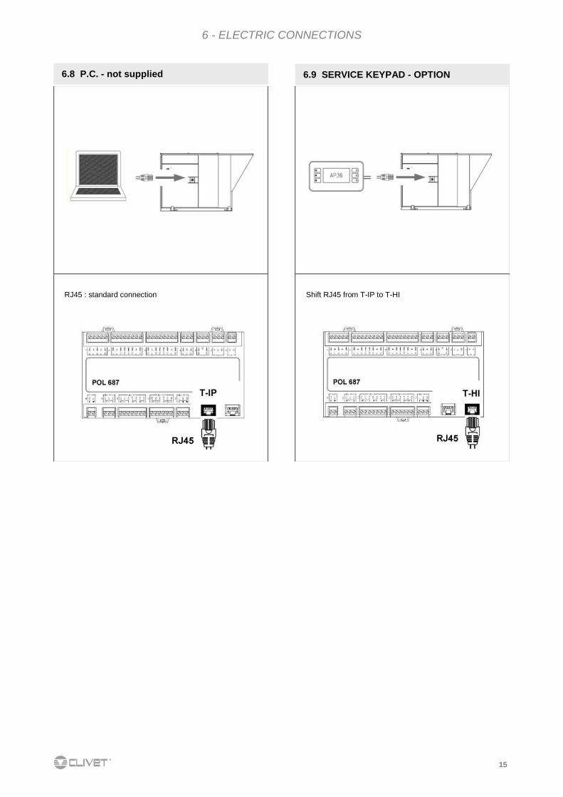
6.9 SERVICE KEYPAD - OPTION 6.8 P.C. - not supplied
Shift RJ45 from T-IP to T-HI RJ45 : standard connection
6 - ELECTRIC CONNECTIONS
16
6 - ELECTRIC CONNECTIONS
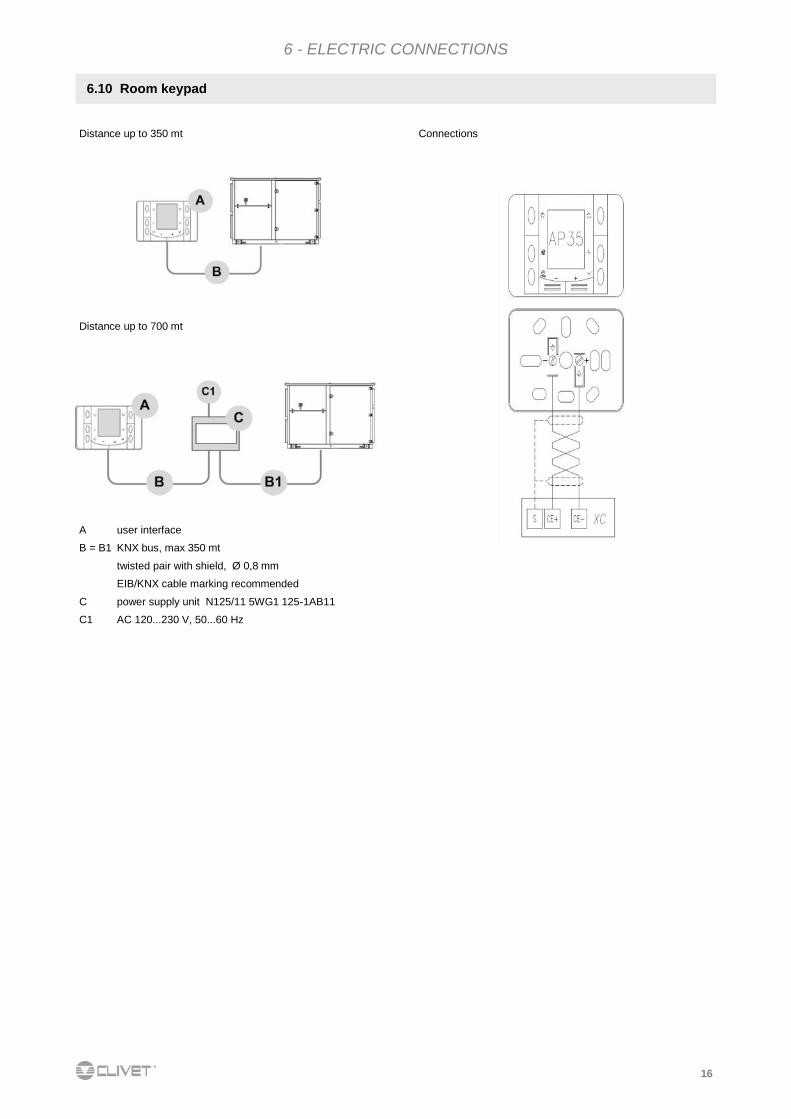
6.10 Room keypad
Distance up to 350 mt Connections
Distance up to 700 mt
A user interface
B = B1 KNX bus, max 350 mt
twisted pair with shield, Ø 0,8 mm
EIB/KNX cable marking recommended
C power supply unit N125/11 5WG1 125-1AB11
C1 AC 120...230 V, 50...60 Hz
17
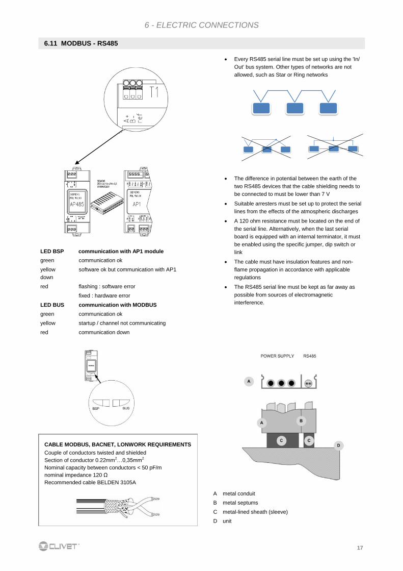
6.11 MODBUS - RS485
6 - ELECTRIC CONNECTIONS
LED BSP communication with AP1 module
green communication ok
yellow software ok but communication with AP1
down
red flashing : software error
fixed : hardware error
LED BUS communication with MODBUS
green communication ok
yellow startup / channel not communicating
red communication down
Every RS485 serial line must be set up using the 'In/
Out' bus system. Other types of networks are not
allowed, such as Star or Ring networks
The difference in potential between the earth of the
two RS485 devices that the cable shielding needs to
be connected to must be lower than 7 V
Suitable arresters must be set up to protect the serial
lines from the effects of the atmospheric discharges
A 120 ohm resistance must be located on the end of
the serial line. Alternatively, when the last serial
board is equipped with an internal terminator, it must
be enabled using the specific jumper, dip switch or
link
The cable must have insulation features and non-
flame propagation in accordance with applicable
regulations
The RS485 serial line must be kept as far away as
possible from sources of electromagnetic
interference.
A metal conduit
B metal septums
C metal-lined sheath (sleeve)
D unit
CABLE MODBUS, BACNET, LONWORK REQUIREMENTS
Couple of conductors twisted and shielded
Section of conductor 0.22mm2…0,35mm2
Nominal capacity between conductors < 50 pF/m
nominal impedance 120 Ω
Recommended cable BELDEN 3105A
18
6 - ELECTRIC CONNECTIONS
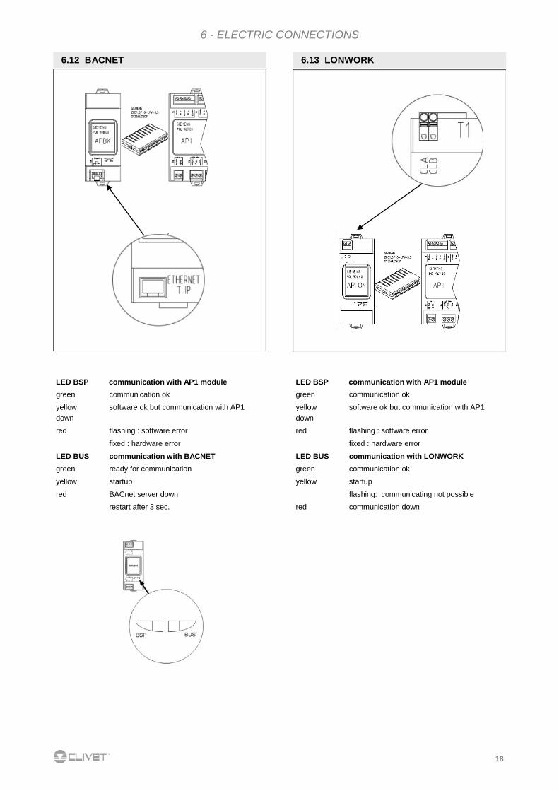
6.12 BACNET 6.13 LONWORK
LED BSP communication with AP1 module
green communication ok
yellow software ok but communication with AP1
down
red flashing : software error
fixed : hardware error
LED BUS communication with BACNET
green ready for communication
yellow startup
red BACnet server down
restart after 3 sec.
LED BSP communication with AP1 module
green communication ok
yellow software ok but communication with AP1
down
red flashing : software error
fixed : hardware error
LED BUS communication with LONWORK
green communication ok
yellow startup
flashing: communicating not possible
red communication down
19
7 - START-UP
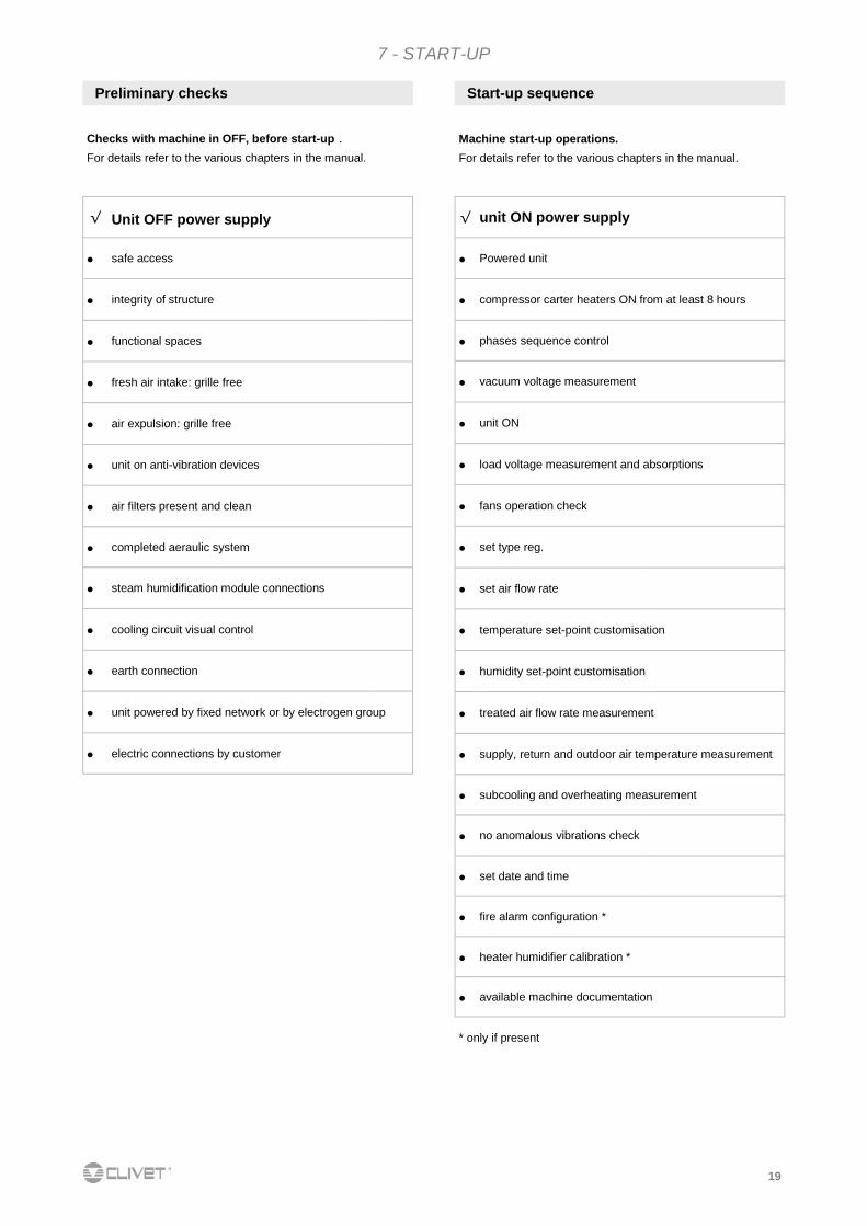
Preliminary checks
Checks with machine in OFF, before start-up . For details refer to the various chapters in the manual.
Start-up sequence
Machine start-up operations.
For details refer to the various chapters in the manual.
√ Unit OFF power supply
safe access
integrity of structure
functional spaces
fresh air intake: grille free
air expulsion: grille free
unit on anti-vibration devices
air filters present and clean
completed aeraulic system
steam humidification module connections
cooling circuit visual control
earth connection
unit powered by fixed network or by electrogen group
electric connections by customer
√ unit ON power supply
Powered unit
compressor carter heaters ON from at least 8 hours
phases sequence control
vacuum voltage measurement
unit ON
load voltage measurement and absorptions
fans operation check
set type reg.
set air flow rate
temperature set-point customisation
humidity set-point customisation
treated air flow rate measurement
supply, return and outdoor air temperature measurement
subcooling and overheating measurement
no anomalous vibrations check
set date and time
fire alarm configuration *
heater humidifier calibration *
available machine documentation
* only if present
20
7 - START-UP
7.1 Preliminary information
The indicated operations must be carried out by qualified
technicians and specifically trained on the product.
Upon request, the after-sales assistance centres execute start-
up.
The electric, hydraulic connections and the other work of the
system are the responsibility of the installer.
Agree the start-up date with the after-sales assistance centre
with sufficient advance
7.2 Preliminary checks
7.3 Cooling circuit
7.4 Hydraulic circuit
Before starting any check, verify that :
the unit is perfectly installed and in compliance with that
reported in this manual
the electric power supply line of the unit is isolated at start-
up
the isolation device of the line is open, blocked and
equipped with relative signal.
1. Visually check the cooling circuit: any oil stains can be
symptom of leaks (caused by, for example, transport,
handling or other).
2. Check the cooling circuit is pressurised: use the machine
pressure gauges, if present, or service pressure gauges.
3. Check all service sockets are closed with relative plugs;
their absence may determine coolant leaks
!
Only with hot water coil - humidifier options 1. Find out if, before connecting the unit, the hydraulic
system has been washed and the washing water drained.
2. Check the hydraulic circuit has been loaded and
pressurised.
3. Check the shut-off valves on the circuit are in "OPEN"
position.
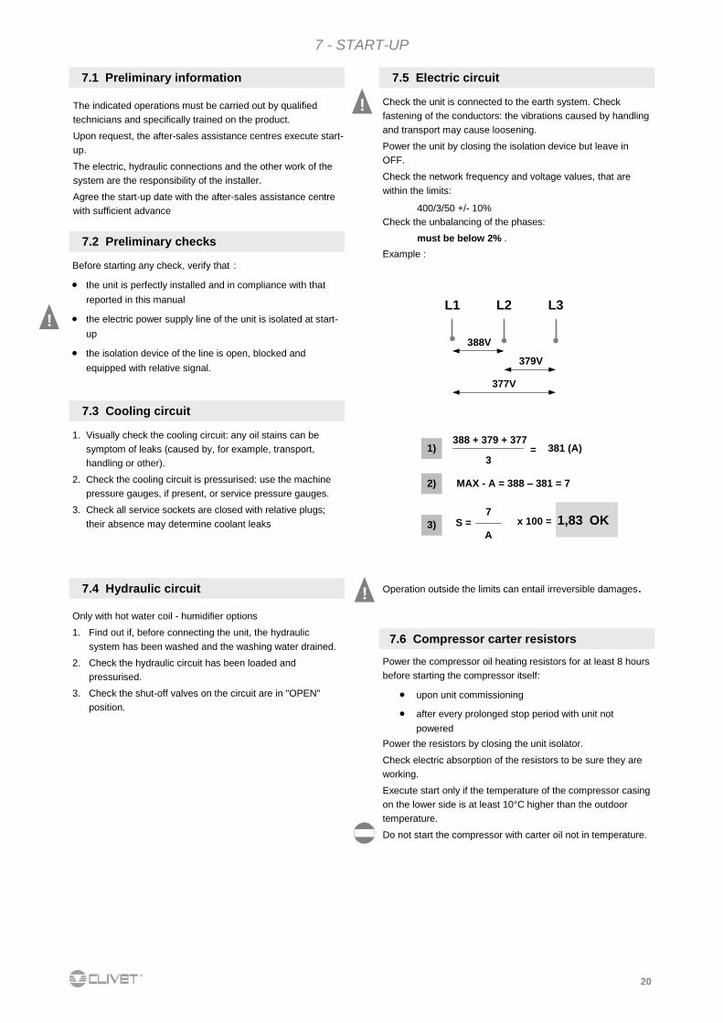
! Check the unit is connected to the earth system. Check
fastening of the conductors: the vibrations caused by handling
and transport may cause loosening.
Power the unit by closing the isolation device but leave in
OFF.
Check the network frequency and voltage values, that are
within the limits:
400/3/50 +/- 10%
Check the unbalancing of the phases: must be below 2% .
Example :
7.5 Electric circuit
Operation outside the limits can entail irreversible damages.
L1 L2 L3
388V
379V
377V
388 + 379 + 377
3= 381 (A)
MAX - A = 388 – 381 = 7
S =7
A
x 100 = 1,83 OK
1)
2)
3)
7.6 Compressor carter resistors
Power the compressor oil heating resistors for at least 8 hours
before starting the compressor itself:
upon unit commissioning
after every prolonged stop period with unit not
powered
Power the resistors by closing the unit isolator.
Check electric absorption of the resistors to be sure they are
working.
Execute start only if the temperature of the compressor casing
on the lower side is at least 10°C higher than the outdoor
temperature.
Do not start the compressor with carter oil not in temperature.
!
21
7.8 Scroll compressors (size 2, 3, 4, 5, 6)
Refer to 7.11, 7.12, 7.13.
1. Define operation type
- maximum capacity available (MC)
- constant supply control (CS)
- high air flow (HA)
2. set air flow setpoint
3. set temperature setpoint
4. set humidity setpoint
5. confirm setting
7.10 Operation type setting
7 - START-UP
i
7.14 Start-up report
To detect the objective operational conditions is useful to
control the unit over time.
With the unit running, meaning in stable conditions and near
the work ones, detect the following data:
Overall absorptions and voltages with unit in full load
Absorptions of the various electric loads
(compressors, fans, pumps etc)
Temperatures and flow rates of the various fluids
(water, air) at input and output of the unit
Temperatures and pressures in the feature points of
the cooling circuit (compressor, liquid, suction drain/
unload)
The detections must be kept and made available during
maintenance interventions.
From Directive 97/23 EC PED derive the prescriptions for the
installers, the users and the maintenance operators of the unit
also.
Refer to the local implemented standards; in synthesis and for
merely indicative purposes:
Compulsory check of first system:
only for units assembled on site by the installer (e.g.
condensing + direct expansion unit)
Declaration of start-up:
for all units
Periodical checks:
to be carried out as frequently as defined by the
Manufacturer
(see MAINTENANCE section) .
7.15 EC Directive 97/23 PED
Check the air and water temperatures are within the
operational limits.
Start the unit; refer to the "Adjustment" section for indications
on the control system.
With the unit running, meaning in stable conditions and near
the work ones, check:
power supply voltage
unit overall absorption
absorption of the individual electric loads.
7.7 Voltages
Check the remote controls (ON-OFF, etc.) are connected
and, if necessary, enabled with relative parameters
(ELECTRIC CONNECTIONS sections and following pages)
Check the probes or optional components are connected and
enabled with the relative parameters.
7.9 Remote consents
The Scroll compressors have only one direction of rotation.
In the event that the direction is reversed, the compressor will
not be damaged, but its noisiness will increase and pumping
will be negatively affected.
After a few minutes, the compressor will stop because of the
activation of the thermal protection.
In this event, cut the power and reverse the 2 phases on the
machine power.
Prevent the compressor from working with in reverse rotation:
more than 2-3 anomalous starts up can damage it.
Make sure the direction of rotation is correct, measure the
condensation and suction pressure.
Pressure must clearly differ: at the start, the suction pressure
decreases whilst the condensation pressure increases.
22
7 - START-UP
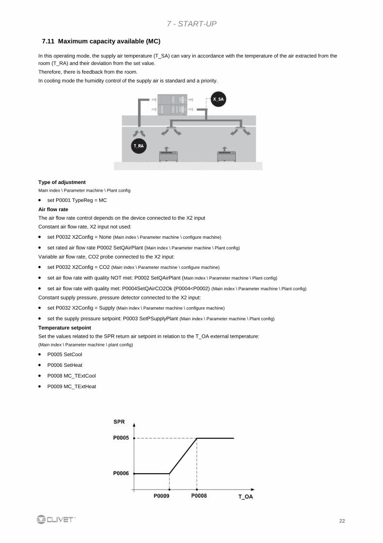
7.11 Maximum capacity available (MC)
In this operating mode, the supply air temperature (T_SA) can vary in accordance with the temperature of the air extracted from the
room (T_RA) and their deviation from the set value.
Therefore, there is feedback from the room.
In cooling mode the humidity control of the supply air is standard and a priority.
Type of adjustment
Main index \ Parameter machine \ Plant config
set P0001 TypeReg = MC
Air flow rate
The air flow rate control depends on the device connected to the X2 input
Constant air flow rate, X2 input not used:
set P0032 X2Config = None (Main index \ Parameter machine \ configure machine)
set rated air flow rate P0002 SetQAirPlant (Main index \ Parameter machine \ Plant config)
Variable air flow rate, CO2 probe connected to the X2 input:
set P0032 X2Config = CO2 (Main index \ Parameter machine \ configure machine)
set air flow rate with quality NOT met: P0002 SetQAirPlant (Main index \ Parameter machine \ Plant config)
set air flow rate with quality met: P0004SetQAirCO2Ok (P0004<P0002) (Main index \ Parameter machine \ Plant config)
Constant supply pressure, pressure detector connected to the X2 input:
set P0032 X2Config = Supply (Main index \ Parameter machine \ configure machine)
set the supply pressure setpoint: P0003 SetPSupplyPlant (Main index \ Parameter machine \ Plant config)
Temperature setpoint
Set the values related to the SPR return air setpoint in relation to the T_OA external temperature:
(Main index \ Parameter machine \ plant config)
P0005 SetCool
P0006 SetHeat
P0008 MC_TExtCool
P0009 MC_TExtHeat
23
7 - START-UP
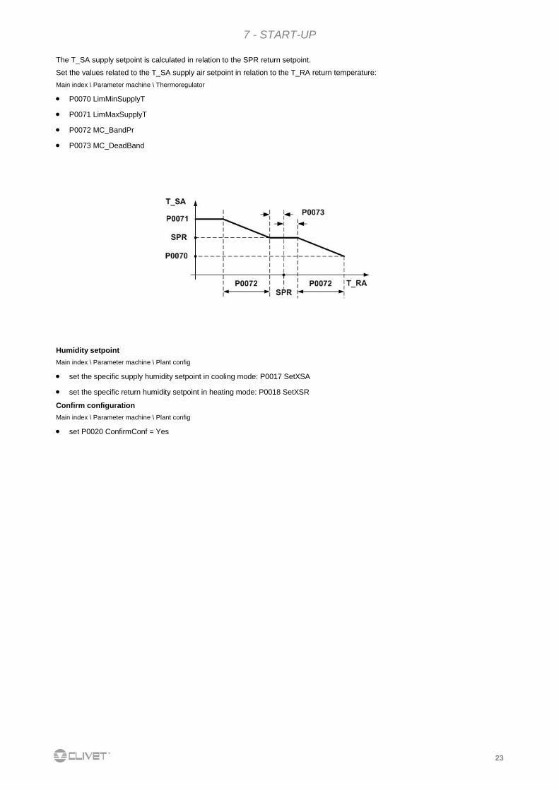
The T_SA supply setpoint is calculated in relation to the SPR return setpoint.
Set the values related to the T_SA supply air setpoint in relation to the T_RA return temperature:
Main index \ Parameter machine \ Thermoregulator
P0070 LimMinSupplyT
P0071 LimMaxSupplyT
P0072 MC_BandPr
P0073 MC_DeadBand
Humidity setpoint
Main index \ Parameter machine \ Plant config
set the specific supply humidity setpoint in cooling mode: P0017 SetXSA
set the specific return humidity setpoint in heating mode: P0018 SetXSR
Confirm configuration
Main index \ Parameter machine \ Plant config
set P0020 ConfirmConf = Yes
24
7 - START-UP
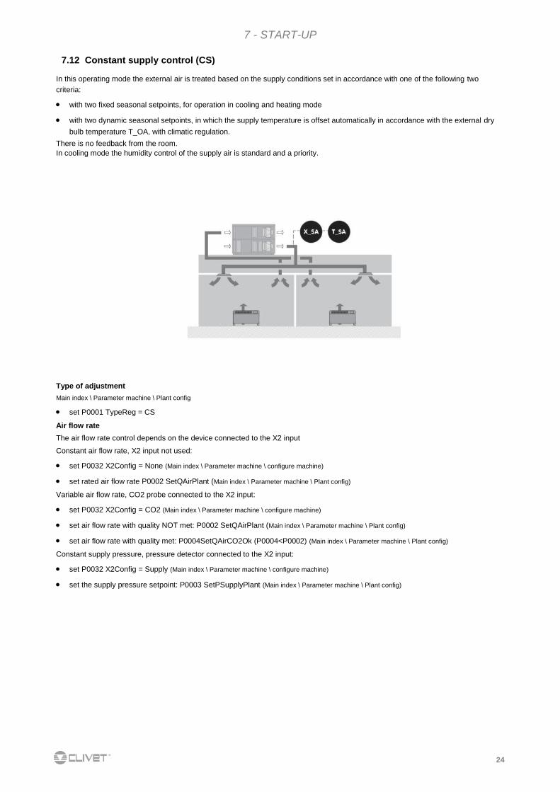
7.12 Constant supply control (CS)
In this operating mode the external air is treated based on the supply conditions set in accordance with one of the following two
criteria:
with two fixed seasonal setpoints, for operation in cooling and heating mode
with two dynamic seasonal setpoints, in which the supply temperature is offset automatically in accordance with the external dry
bulb temperature T_OA, with climatic regulation.
There is no feedback from the room. In cooling mode the humidity control of the supply air is standard and a priority.
Type of adjustment
Main index \ Parameter machine \ Plant config
set P0001 TypeReg = CS
Air flow rate
The air flow rate control depends on the device connected to the X2 input
Constant air flow rate, X2 input not used:
set P0032 X2Config = None (Main index \ Parameter machine \ configure machine)
set rated air flow rate P0002 SetQAirPlant (Main index \ Parameter machine \ Plant config)
Variable air flow rate, CO2 probe connected to the X2 input:
set P0032 X2Config = CO2 (Main index \ Parameter machine \ configure machine)
set air flow rate with quality NOT met: P0002 SetQAirPlant (Main index \ Parameter machine \ Plant config)
set air flow rate with quality met: P0004SetQAirCO2Ok (P0004<P0002) (Main index \ Parameter machine \ Plant config)
Constant supply pressure, pressure detector connected to the X2 input:
set P0032 X2Config = Supply (Main index \ Parameter machine \ configure machine)
set the supply pressure setpoint: P0003 SetPSupplyPlant (Main index \ Parameter machine \ Plant config)
25
7 - START-UP
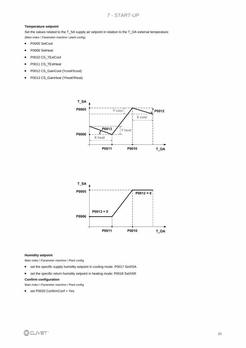
Temperature setpoint
Set the values related to the T_SA supply air setpoint in relation to the T_OA external temperature:
(Main index \ Parameter machine \ plant config)
P0005 SetCool
P0006 SetHeat
P0010 CS_TExtCool
P0011 CS_TExtHeat
P0012 CS_GainCool (Ycool/Xcool)
P0013 CS_GainHeat (Yheat/Xheat)
Humidity setpoint
Main index \ Parameter machine \ Plant config
set the specific supply humidity setpoint in cooling mode: P0017 SetXSA
set the specific return humidity setpoint in heating mode: P0018 SetXSR
Confirm configuration
Main index \ Parameter machine \ Plant config
set P0020 ConfirmConf = Yes
26
7 - START-UP
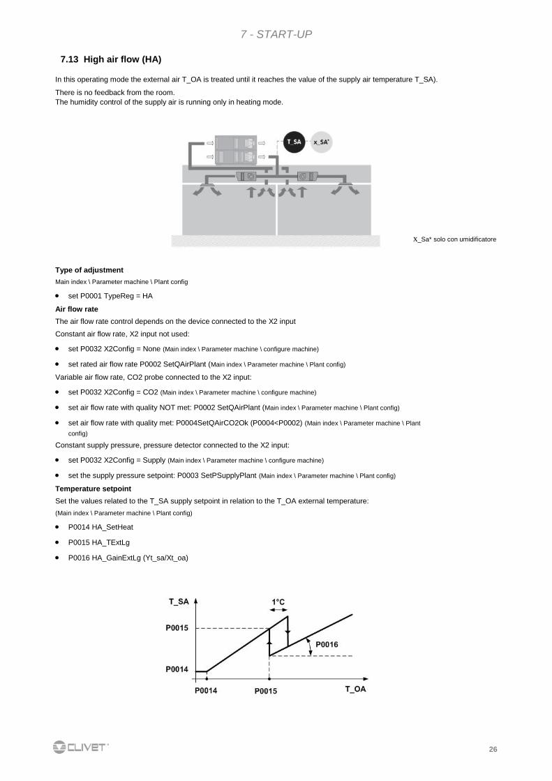
7.13 High air flow (HA)
x_Sa* solo con umidificatore
Type of adjustment
Main index \ Parameter machine \ Plant config
set P0001 TypeReg = HA
Air flow rate
The air flow rate control depends on the device connected to the X2 input
Constant air flow rate, X2 input not used:
set P0032 X2Config = None (Main index \ Parameter machine \ configure machine)
set rated air flow rate P0002 SetQAirPlant (Main index \ Parameter machine \ Plant config)
Variable air flow rate, CO2 probe connected to the X2 input:
set P0032 X2Config = CO2 (Main index \ Parameter machine \ configure machine)
set air flow rate with quality NOT met: P0002 SetQAirPlant (Main index \ Parameter machine \ Plant config)
set air flow rate with quality met: P0004SetQAirCO2Ok (P0004<P0002) (Main index \ Parameter machine \ Plant
config)
Constant supply pressure, pressure detector connected to the X2 input:
set P0032 X2Config = Supply (Main index \ Parameter machine \ configure machine)
set the supply pressure setpoint: P0003 SetPSupplyPlant (Main index \ Parameter machine \ Plant config)
Temperature setpoint
Set the values related to the T_SA supply setpoint in relation to the T_OA external temperature:
(Main index \ Parameter machine \ Plant config)
P0014 HA_SetHeat
P0015 HA_TExtLg
P0016 HA_GainExtLg (Yt_sa/Xt_oa)
In this operating mode the external air T_OA is treated until it reaches the value of the supply air temperature T_SA).
There is no feedback from the room. The humidity control of the supply air is running only in heating mode.

27
7 - START-UP
Humidity setpoint
Main index \ Parameter machine \ Plant config
set the specific return humidity setpoint in heating mode: P0018 SetXSR
Confirm configuration
Main index \ Parameter machine \ Plant config
set P0020 ConfirmConf = Yes
28
8 - CONTROL
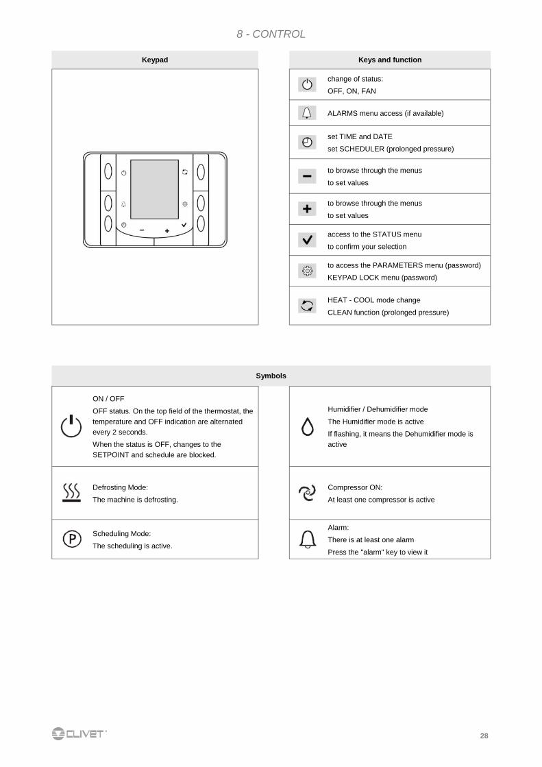
Keypad Keys and function
change of status:
OFF, ON, FAN
ALARMS menu access (if available)
set TIME and DATE
set SCHEDULER (prolonged pressure)
to browse through the menus
to set values
to browse through the menus
to set values
access to the STATUS menu
to confirm your selection
to access the PARAMETERS menu (password)
KEYPAD LOCK menu (password)
HEAT - COOL mode change
CLEAN function (prolonged pressure)
Symbols
ON / OFF
OFF status. On the top field of the thermostat, the
temperature and OFF indication are alternated
every 2 seconds.
When the status is OFF, changes to the
SETPOINT and schedule are blocked.
Humidifier / Dehumidifier mode
The Humidifier mode is active
If flashing, it means the Dehumidifier mode is
active
Defrosting Mode:
The machine is defrosting.
Compressor ON:
At least one compressor is active
Scheduling Mode:
The scheduling is active.
Alarm:
There is at least one alarm
Press the "alarm" key to view it

29
8 - CONTROL
8.1 PARAMETERS MENU
16.3 C°
17:00
P1
0
COD
47
P1
1
ESC
press
the access by password is reserved to
qualified personnel, the parameters
changes can cause malfunctions.
enter password (0047)
confirm
scroll the parameters
enable the parameter change
P1 starts flashing
change the value of the parameter
confirm the new value
select
to enable the new value and exit
when the time is displayed
it is possible to carry out other
operations
code Short description Description
0 PriorityCmd Priority commands On/change mode (0=keyboard, 1=BMS)
1 Enscheduler Enable schedular (0=disable, 1=enable)
30
8 - CONTROL
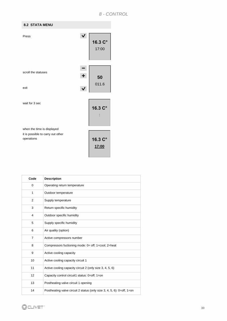
8.2 STATA MENU
16.3 C°
17:00
50
011.6
Press
scroll the statuses
exit
wait for 3 sec
when the time is displayed
it is possible to carry out other
operations
16.3 C°
:
16.3 C°
17:00
Code Description
0 Operating return temperature
1 Outdoor temperature
2 Supply temperature
3 Return specific humidity
4 Outdoor specific humidity
5 Supply specific humidity
6 Air quality (option)
7 Active compressors number
8 Compressors fuctioning mode: 0= off; 1=cool; 2=heat
9 Active cooling capacity
10 Active cooling capacity circuit 1
11 Active cooling capacity circuit 2 (only size 3, 4, 5, 6)
12 Capacity control circuit1 status: 0=off; 1=on
13 Postheating valve circuit 1 opening
14 Postheating valve circuit 2 status (only size 3, 4, 5, 6): 0=off, 1=on
31
8 - CONTROL
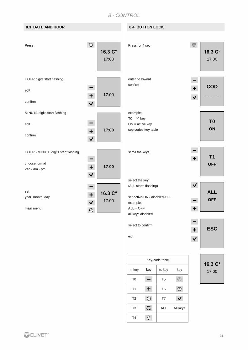
8.4 BUTTON LOCK
Press for 4 sec.
enter password
confirm
example:
T0 = "-" key
ON = active key
see codes-key table
scroll the keys
select the key
(ALL starts flashing)
set active-ON / disabled-OFF
example:
ALL = OFF
all keys disabled
select to confirm
exit
16.3 C°
17:00
COD
_ _ _ _
T0
ON
Key-code table
n. key key n. key key
T0
T5
T1
T6
T2
T7
T3
ALL All keys
T4
T1
OFF
ALL
OFF
ESC
16.3 C°
17:00
8.3 DATE AND HOUR
Press
HOUR digits start flashing
edit
confirm
MINUTE digits start flashing
edit
confirm
HOUR - MINUTE digits start flashing
choose format
24h / am - pm
set
year, month, day
main menu
16.3 C°
17:00
17:00
17:00
17:00
16.3 C°
17:00
32
8 - CONTROL
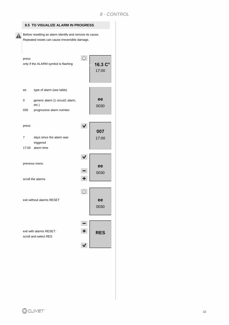
press
only if the ALARM symbol is flashing
ee type of alarm (see table)
0 generic alarm (1 circuit1 alarm,
etc.)
030 progressive alarm number
press
7 days since the alarm was
triggered
17:00 alarm time
previous menu
scroll the alarms
exit without alarms RESET
exit with alarms RESET:
scroll and select RES
8.5 TO VISUALIZE ALARM IN PROGRESS
Before resetting an alarm identify and remove its cause.
Repeated resets can cause irreversible damage.
16.3 C°
17:00
ee
0030
007
17:00
ee
0030
ee
0030
RES
33
8 - CONTROL
1 3 4
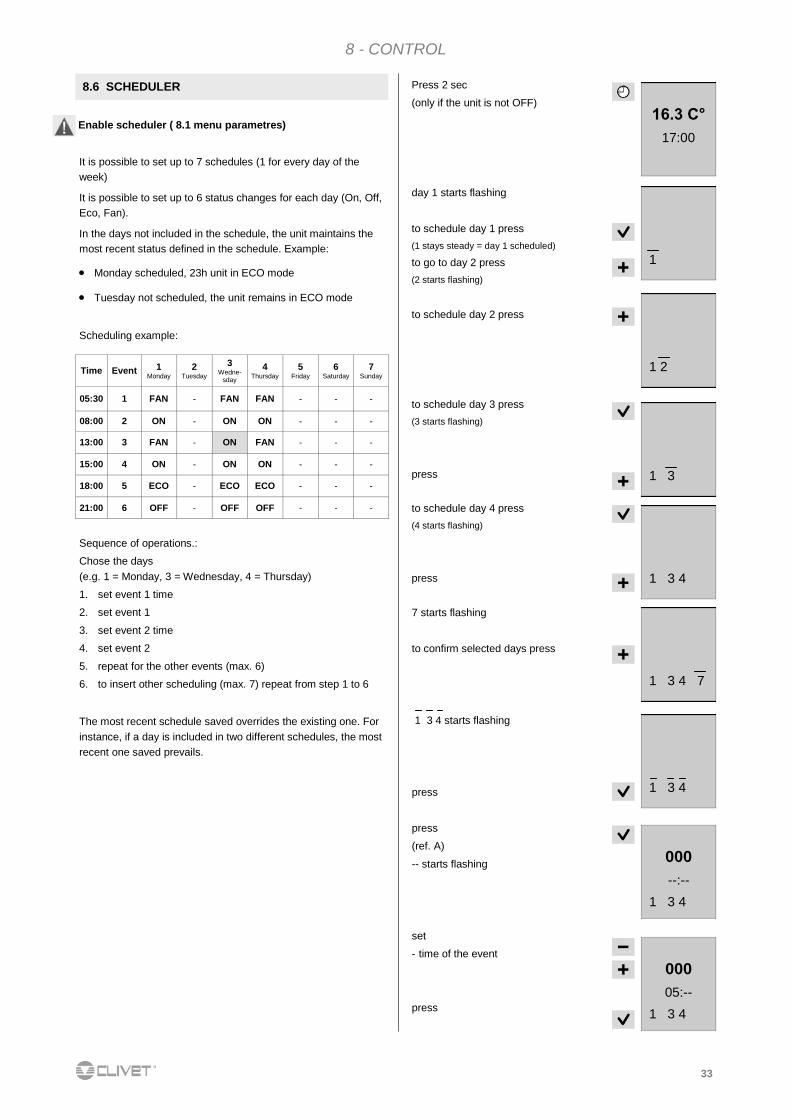
Press 2 sec
(only if the unit is not OFF)
day 1 starts flashing
to schedule day 1 press
(1 stays steady = day 1 scheduled)
to go to day 2 press
(2 starts flashing)
to schedule day 2 press
to schedule day 3 press
(3 starts flashing)
press
to schedule day 4 press
(4 starts flashing)
press
16.3 C°
17:00
1
1 2
1 3
1 3 4 7
8.6 SCHEDULER
It is possible to set up to 7 schedules (1 for every day of the
week)
It is possible to set up to 6 status changes for each day (On, Off,
Eco, Fan).
In the days not included in the schedule, the unit maintains the
most recent status defined in the schedule. Example:
Monday scheduled, 23h unit in ECO mode
Tuesday not scheduled, the unit remains in ECO mode
Scheduling example:
7 starts flashing
to confirm selected days press
1 3 4 starts flashing
press
press
(ref. A)
-- starts flashing
set
- time of the event
press
Enable scheduler ( 8.1 menu parametres)
Time Event 1 Monday
2 Tuesday
3 Wedne-
sday
4 Thursday
5 Friday
6 Saturday
7 Sunday
05:30 1 FAN - FAN FAN - - -
08:00 2 ON - ON ON - - -
13:00 3 FAN - ON FAN - - -
15:00 4 ON - ON ON - - -
18:00 5 ECO - ECO ECO - - -
21:00 6 OFF - OFF OFF - - -
Sequence of operations.:
Chose the days
(e.g. 1 = Monday, 3 = Wednesday, 4 = Thursday)
1. set event 1 time
2. set event 1
3. set event 2 time
4. set event 2
5. repeat for the other events (max. 6)
6. to insert other scheduling (max. 7) repeat from step 1 to 6
The most recent schedule saved overrides the existing one. For
instance, if a day is included in two different schedules, the most
recent one saved prevails.
1 3 4
000
--:--
1 3 4
000
05:--
1 3 4
34
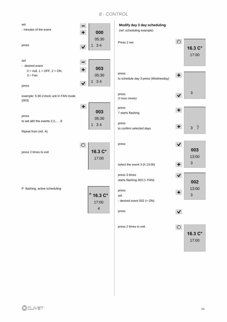
8 - CONTROL
set
- minutes of the event
press
set
- desired event
0 = null, 1 = OFF, 2 = ON,
3 = Fan
press
example: 5:30 o'clock unit in FAN mode
(003)
press
to set altri the events 2,3,…..6
Ripeat from (ref. A)
press 2 times to exit
003
05:30
1 3 4
000
05:30
1 3 4
P 16.3 C°
17:00
4
P flashing, active scheduling
Press 2 sec
press
to schedule day 3 press (Wednesday)
press
(3 stays steady)
press
7 starts flashing
press
to confirm selected days
press
select the event 3 (h.13:00)
press 3 times
starts flashing 003 (= FAN)
press
set
- desired event 002 (= ON)
press
press 2 times to exit
16.3 C°
17:00
3
3 7
003
13:00
3
002
13:00
3
16.3 C°
17:00
16.3 C°
17:00
003
05:30
1 3 4
Modify day 3 day scheduling
(ref. scheduling example)
35
8 - CONTROL
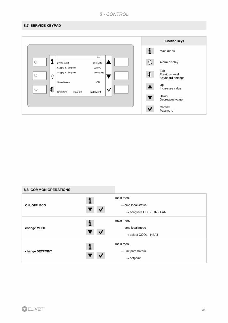
8.7 SERVICE KEYPAD
Function keys
Main menu
Alarm display
Exit Previous level Keyboard settings
Up Increases value
Down Decreases value
Confirm Password
1/7
27.03.2013 10:15:30
Supply T. Setpoint 22.0°C
Supply X. Setpoint 10.0 g/kg
StatoAttuale ON
Cmp:23% Res: Off Battery:Off
8.8 COMMON OPERATIONS
ON, OFF, ECO
main menu
→ cmd local status
→ scegliere OFF - ON - FAN
change MODE
main menu
→ cmd local mode
→ select COOL - HEAT
change SETPOINT
main menu
→ unit parameters
→ setpoint
36
8 - CONTROL
Select
Confirm
Main index
Cmd Local state On
Cmd Local mode Cool
Unit stata
Unit parameters
System Objects
Schedulatore
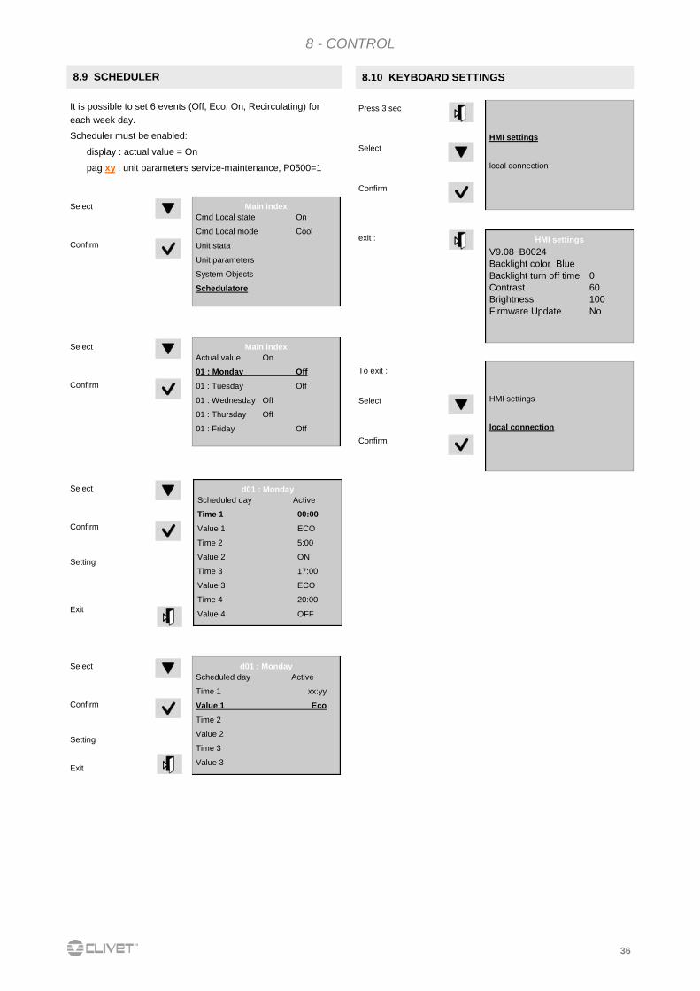
8.9 SCHEDULER
Select
Confirm
Main index
Actual value On
01 : Monday Off
01 : Tuesday Off
01 : Wednesday Off
01 : Thursday Off
01 : Friday Off
Select
Confirm
It is possible to set 6 events (Off, Eco, On, Recirculating) for
each week day.
Scheduler must be enabled:
display : actual value = On
pag xy : unit parameters service-maintenance, P0500=1
Setting Exit
Select
Confirm
d01 : Monday
Scheduled day Active
Time 1 xx:yy
Value 1 Eco
Time 2
Value 2
Time 3
Value 3
Setting Exit
d01 : Monday
Scheduled day Active
Time 1 00:00
Value 1 ECO
Time 2 5:00
Value 2 ON
Time 3 17:00
Value 3 ECO
Time 4 20:00
Value 4 OFF
8.10 KEYBOARD SETTINGS
HMI settings
local connection
Press 3 sec
HMI settings
V9.08 B0024
Backlight color Blue
Backlight turn off time 0
Contrast 60
Brightness 100
Firmware Update No
Select
Confirm
HMI settings
local connection
Select
Confirm
To exit :
exit :

37
8 - CONTROL
Press Last alarm
Press
Fault = active alarm
Ok = resetted alarm
Reset alarm log : select RESET select EXECUTED
8.11 ALARMS
alarm ing
----------
----------
----------
Reset
Press alarm list (*) reset alarms access
Alarm list
Acknowledge (*) 3
+ eE001 : Monitore fase : Fault
- EE003 : Guasto P1 Util : Ok
+ EE003 : Guasto P1 Util : Fault
Press alarm log (*) reset alarms access
Before resetting an alarm identify and remove its cause.
Repeated resets can cause irreversible damage.
alarm log detail
+ eE001 : Phase monitor : Fault
1 Critico (A)
14.02.2012 11.30.10
alarm log
Acknowledge (*) Passivo
10
+ eE001 : Monitore fase : Fault
- EE003 : Guasto P1 Util : Ok
+ EE003 : Guasto P1 Util : Fault
38
8 - CONTROL
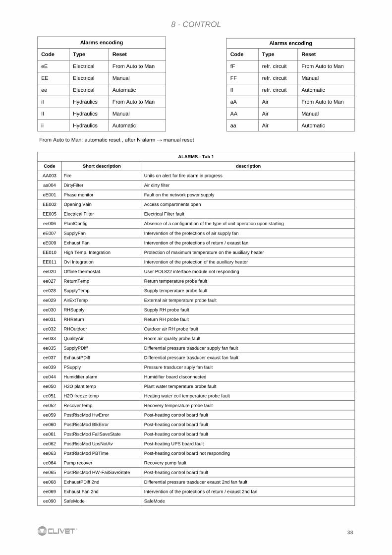
ALARMS - Tab 1
Code Short description description
AA003 Fire Units on alert for fire alarm in progress
aa004 DirtyFilter Air dirty filter
eE001 Phase monitor Fault on the network power supply
EE002 Opening Vain Access compartments open
EE005 Electrical Filter Electrical Filter fault
ee006 PlantConfig Absence of a configuration of the type of unit operation upon starting
eE007 SupplyFan Intervention of the protections of air supply fan
eE009 Exhaust Fan Intervention of the protections of return / exaust fan
EE010 High Temp. Integration Protection of maximum temperature on the auxiliary heater
EE011 Ovl Integration Intervention of the protection of the auxiliary heater
ee020 Offline thermostat. User POL822 interface module not responding
ee027 ReturnTemp Return temperature probe fault
ee028 SupplyTemp Supply temperature probe fault
ee029 AirExtTemp External air temperature probe fault
ee030 RHSupply Supply RH probe fault
ee031 RHReturn Return RH probe fault
ee032 RHOutdoor Outdoor air RH probe fault
ee033 QualityAir Room air quality probe fault
ee035 SupplyPDiff Differential pressure trasducer supply fan fault
ee037 ExhaustPDiff Differential pressure trasducer exaust fan fault
ee039 PSupply Pressure trasducer suply fan fault
ee044 Humidifier alarm Humidifier board disconnected
ee050 H2O plant temp Plant water temperature probe fault
ee051 H2O freeze temp Heating water coil temperature probe fault
ee052 Recover temp Recovery temperature probe fault
ee059 PostRiscMod HwError Post-heating control board fault
ee060 PostRiscMod BlkError Post-heating control board fault
ee061 PostRiscMod FailSaveState Post-heating control board fault
ee062 PostRiscMod UpsNotAv Post-heating UPS board fault
ee063 PostRiscMod PBTime Post-heating control board not responding
ee064 Pump recover Recovery pump fault
ee065 PostRiscMod HW-FailSaveState Post-heating control board fault
ee068 ExhaustPDiff 2nd Differential pressure trasducer exaust 2nd fan fault
ee069 Exhaust Fan 2nd Intervention of the protections of return / exaust 2nd fan
ee090 SafeMode SafeMode
Alarms encoding
Code Type Reset
eE Electrical From Auto to Man
EE Electrical Manual
ee Electrical Automatic
iI Hydraulics From Auto to Man
II Hydraulics Manual
ii Hydraulics Automatic
Alarms encoding
Code Type Reset
fF refr. circuit From Auto to Man
FF refr. circuit Manual
ff refr. circuit Automatic
aA Air From Auto to Man
AA Air Manual
aa Air Automatic
From Auto to Man: automatic reset , after N alarm → manual reset
39
8 - CONTROL
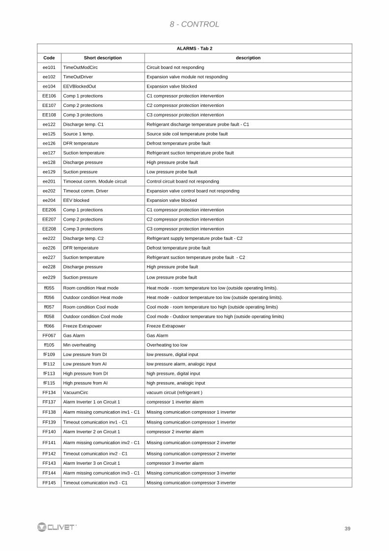
ALARMS - Tab 2
Code Short description description
ee101 TimeOutModCirc Circuit board not responding
ee102 TimeOutDriver Expansion valve module not responding
ee104 EEVBlockedOut Expansion valve blocked
EE106 Comp 1 protections C1 compressor protection intervention
EE107 Comp 2 protections C2 compressor protection intervention
EE108 Comp 3 protections C3 compressor protection intervention
ee122 Discharge temp. C1 Refrigerant discharge temperature probe fault - C1
ee125 Source 1 temp. Source side coil temperature probe fault
ee126 DFR temperature Defrost temperature probe fault
ee127 Suction temperature Refrigerant suction temperature probe fault
ee128 Discharge pressure High pressure probe fault
ee129 Suction pressure Low pressure probe fault
ee201 Timoeout comm. Module circuit Control circuit board not responding
ee202 Timeout comm. Driver Expansion valve control board not responding
ee204 EEV blocked Expansion valve blocked
EE206 Comp 1 protections C1 compressor protection intervention
EE207 Comp 2 protections C2 compressor protection intervention
EE208 Comp 3 protections C3 compressor protection intervention
ee222 Discharge temp. C2 Refrigerant supply temperature probe fault - C2
ee226 DFR temperature Defrost temperature probe fault
ee227 Suction temperature Refrigerant suction temperature probe fault - C2
ee228 Discharge pressure High pressure probe fault
ee229 Suction pressure Low pressure probe fault
ff055 Room condition Heat mode Heat mode - room temperature too low (outside operating limits).
ff056 Outdoor condition Heat mode Heat mode - outdoor temperature too low (outside operating limits).
ff057 Room condition Cool mode Cool mode - room temperature too high (outside operating limits)
ff058 Outdoor condition Cool mode Cool mode - Outdoor temperature too high (outside operating limits)
ff066 Freeze Extrapower Freeze Extrapower
FF067 Gas Alarm Gas Alarm
ff105 Min overheating Overheating too low
fF109 Low pressure from DI low pressure, digital input
fF112 Low pressure from AI low pressure alarm, analogic input
fF113 High pressure from DI high pressure, digital input
fF115 High pressure from AI high pressure, analogic input
FF134 VacuumCirc vacuum circuit (refrigerant )
FF137 Alarm Inverter 1 on Circuit 1 compressor 1 inverter alarm
FF138 Alarm missing comunication inv1 - C1 Missing comunication compressor 1 inverter
FF139 Timeout comunication inv1 - C1 Missing comunication compressor 1 inverter
FF140 Alarm Inverter 2 on Circuit 1 compressor 2 inverter alarm
FF141 Alarm missing comunication inv2 - C1 Missing comunication compressor 2 inverter
FF142 Timeout comunication inv2 - C1 Missing comunication compressor 2 inverter
FF143 Alarm Inverter 3 on Circuit 1 compressor 3 inverter alarm
FF144 Alarm missing comunication inv3 - C1 Missing comunication compressor 3 inverter
FF145 Timeout comunication inv3 - C1 Missing comunication compressor 3 inverter
40
8 - CONTROL
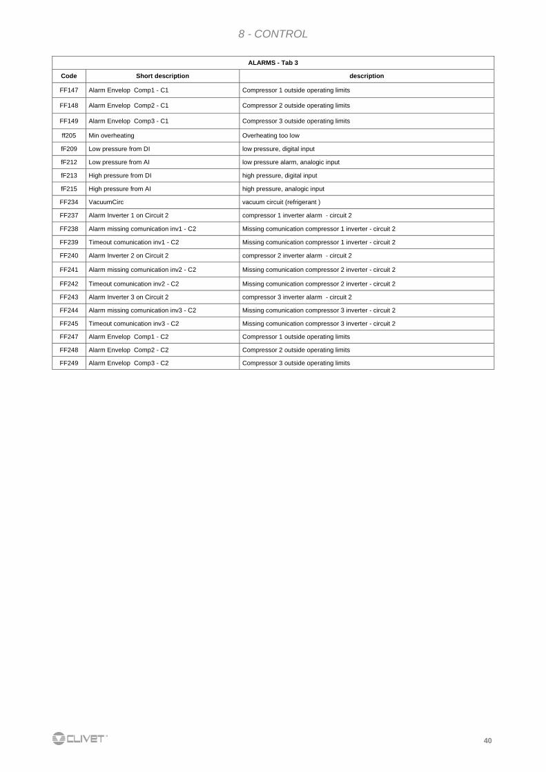
ALARMS - Tab 3
Code Short description description
FF147 Alarm Envelop Comp1 - C1 Compressor 1 outside operating limits
FF148 Alarm Envelop Comp2 - C1 Compressor 2 outside operating limits
FF149 Alarm Envelop Comp3 - C1 Compressor 3 outside operating limits
ff205 Min overheating Overheating too low
fF209 Low pressure from DI low pressure, digital input
fF212 Low pressure from AI low pressure alarm, analogic input
fF213 High pressure from DI high pressure, digital input
fF215 High pressure from AI high pressure, analogic input
FF234 VacuumCirc vacuum circuit (refrigerant )
FF237 Alarm Inverter 1 on Circuit 2 compressor 1 inverter alarm - circuit 2
FF238 Alarm missing comunication inv1 - C2 Missing comunication compressor 1 inverter - circuit 2
FF239 Timeout comunication inv1 - C2 Missing comunication compressor 1 inverter - circuit 2
FF240 Alarm Inverter 2 on Circuit 2 compressor 2 inverter alarm - circuit 2
FF241 Alarm missing comunication inv2 - C2 Missing comunication compressor 2 inverter - circuit 2
FF242 Timeout comunication inv2 - C2 Missing comunication compressor 2 inverter - circuit 2
FF243 Alarm Inverter 3 on Circuit 2 compressor 3 inverter alarm - circuit 2
FF244 Alarm missing comunication inv3 - C2 Missing comunication compressor 3 inverter - circuit 2
FF245 Timeout comunication inv3 - C2 Missing comunication compressor 3 inverter - circuit 2
FF247 Alarm Envelop Comp1 - C2 Compressor 1 outside operating limits
FF248 Alarm Envelop Comp2 - C2 Compressor 2 outside operating limits
FF249 Alarm Envelop Comp3 - C2 Compressor 3 outside operating limits
41
8 - CONTROL
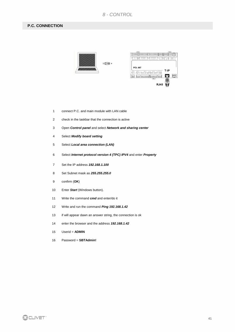
P.C. CONNECTION
1 connect P.C. and main module with LAN cable
2 check in the taskbar that the connection is active
3 Open Control panel and select Network and sharing center
4 Select Modify board setting
5 Select Local area connection (LAN)
6 Select Internet protocol version 4 (TPC) IPV4 and enter Property
7 Set the IP address 192.168.1.100
8 Set Subnet mask as 255.255.255.0
9 confirm (OK)
10 Enter Start (Windows button).
11 Write the command cmd and enter/do it
12 Write and run the command Ping 192.168.1.42
13 if will appear dawn an answer string, the connection is ok
14 enter the browser and the address 192.168.1.42
15 Userid = ADMIN
16 Password = SBTAdmin!
42
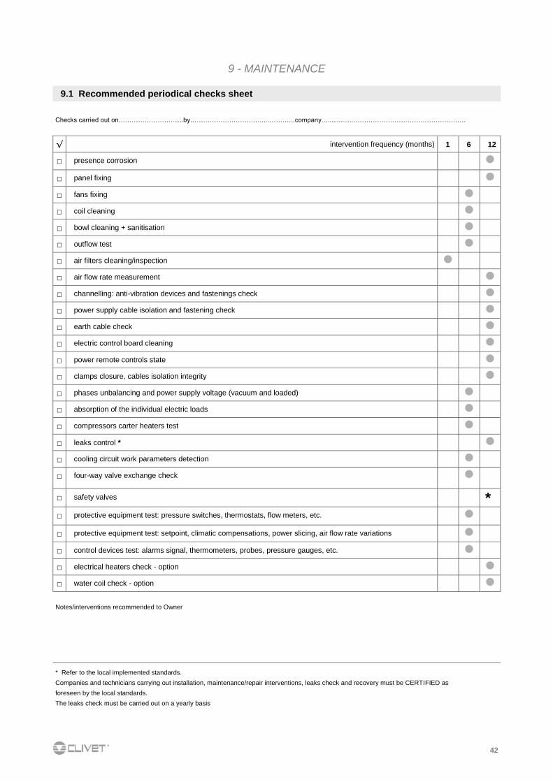
9.1 Recommended periodical checks sheet
Notes/interventions recommended to Owner
* Refer to the local implemented standards.
Companies and technicians carrying out installation, maintenance/repair interventions, leaks check and recovery must be CERTIFIED as
foreseen by the local standards.
The leaks check must be carried out on a yearly basis
9 - MAINTENANCE
Checks carried out on…………………….......by……………………………...………….company…..............…………………………………………….
√ intervention frequency (months) 1 6 12
□ presence corrosion
□ panel fixing
□ fans fixing
□ coil cleaning
□ bowl cleaning + sanitisation
□ outflow test
□ air filters cleaning/inspection
□ air flow rate measurement
□ channelling: anti-vibration devices and fastenings check
□ power supply cable isolation and fastening check
□ earth cable check
□ electric control board cleaning
□ power remote controls state
□ clamps closure, cables isolation integrity
□ phases unbalancing and power supply voltage (vacuum and loaded)
□ absorption of the individual electric loads
□ compressors carter heaters test
□ leaks control *
□ cooling circuit work parameters detection
□ four-way valve exchange check
□ safety valves
* □ protective equipment test: pressure switches, thermostats, flow meters, etc.
□ protective equipment test: setpoint, climatic compensations, power slicing, air flow rate variations
□ control devices test: alarms signal, thermometers, probes, pressure gauges, etc.
□ electrical heaters check - option
□ water coil check - option
43
9 - MAINTENANCE
!
9.2 Generality
Maintenance must be carried out authorised after-sales
assistance centres or by specialised personnel.
Maintenance allows:
maintaining the unit efficient
reduce deterioration speed to which each equipment
is subject in time
collect information and data to understand the
efficiency state of the unit and prevent possible faults
Frequency of the inspections must be at least six-monthly
However, frequency depends on the type of use.
heavy (continuous or highly intermittent, near to
operation limits, etc.)
critical (essential service).
9.3 Frequency of interventions
9.4 Machine schedule
Foresee a machine schedule to keep trace of the
interventions made on the unit.
In this way, it will be easier to adequately schedule the various
interventions and facilitate any troubleshooting.
On the schedule note:
date
type of intervention made
description of intervention
measurements taken, etc. .
If foreseen a long period of inactivity:
disconnect voltage to avoid electric risks or damages
following lightning
prevent the risk of freezing (empty or glycol the
sections of the system exposed to negative
temperatures, keep any antifreeze heaters powered)
It is advised that start-up after a period of inactivity be carried
out by a qualified technician, in particular after seasonal stops
or for seasonal switch-over.
Upon start-up, follow that indicated in the START-UP section.
Plan in advance the technician intervention to prevent
misunderstandings and be able to use the system when
required
9.5 Stand-by
i
i
9.6 Structure
Check the state of the parts constituting the structure.
Treat those parts of the unit subject to oxidation, with paints
act at eliminating or reducing the oxidation phenomena.
Check fastening of the unit external panelling.
Bad fastening give rise to anomalous noises and vibrations.
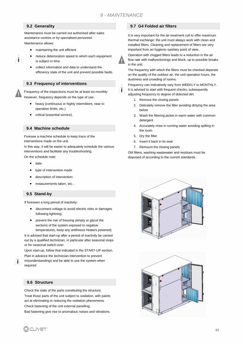
It is very important for the air treatment coil to offer maximum
thermal exchange: the unit must always work with clean and
installed filters. Cleaning and replacement of filters are very
important from an hygienic-sanitary point of view.
Operation with clogged filters leads to a reduction in the air
flow rate with malfunctionings and block, up to possible breaks
in the unit.
The frequency with which the filters must be checked depends
on the quality of the outdoor air, the unit operation hours, the
dustiness and crowding of rooms.
Frequency can indicatively vary from WEEKLY to MONTHLY.
It is advised to start with frequent checks, subsequently
adjusting frequency to degree of detected dirt.
1. Remove the closing panels
2. Delicately remove the filter avoiding dirtying the area
below
3. Wash the filtering jacket in warm water with common
detergent
4. Accurately rinse in running water avoiding spilling in
the room
5. Dry the filter
6. Insert it back in its seat
7. Remount the closing panels
Old filters, washing wastewater and residues must be
disposed of according to the current standards.
9.7 G4 Folded air filters
!
i
44
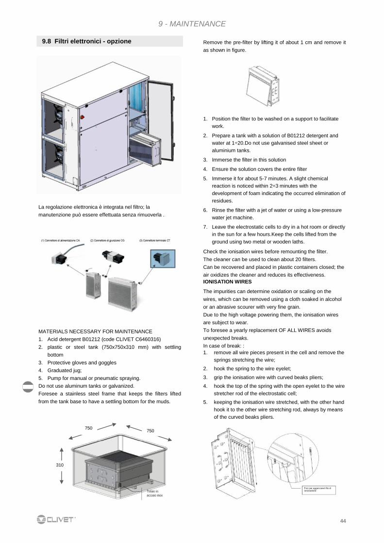
9.8 Filtri elettronici - opzione
La regolazione elettronica è integrata nel filtro; la
manutenzione può essere effettuata senza rimuoverla .
750 750
310
9 - MAINTENANCE
MATERIALS NECESSARY FOR MAINTENANCE 1. Acid detergent B01212 (code CLIVET C6460316)
2. plastic or steel tank (750x750x310 mm) with settling
bottom
3. Protective gloves and goggles
4. Graduated jug;
5. Pump for manual or pneumatic spraying.
Do not use aluminum tanks or galvanized.
Foresee a stainless steel frame that keeps the filters lifted
from the tank base to have a settling bottom for the muds.
Remove the pre-filter by lifting it of about 1 cm and remove it
as shown in figure.
1. Position the filter to be washed on a support to facilitate
work.
2. Prepare a tank with a solution of B01212 detergent and
water at 1÷20.Do not use galvanised steel sheet or
aluminium tanks.
3. Immerse the filter in this solution
4. Ensure the solution covers the entire filter
5. Immerse it for about 5-7 minutes. A slight chemical
reaction is noticed within 2÷3 minutes with the
development of foam indicating the occurred elimination of
residues.
6. Rinse the filter with a jet of water or using a low-pressure
water jet machine.
7. Leave the electrostatic cells to dry in a hot room or directly
in the sun for a few hours.Keep the cells lifted from the
ground using two metal or wooden laths.
Check the ionisation wires before remounting the filter.
The cleaner can be used to clean about 20 filters.
Can be recovered and placed in plastic containers closed; the
air oxidizes the cleaner and reduces its effectiveness.
IONISATION WIRES
The impurities can determine oxidation or scaling on the
wires, which can be removed using a cloth soaked in alcohol
or an abrasive scourer with very fine grain.
Due to the high voltage powering them, the ionisation wires
are subject to wear.
To foresee a yearly replacement OF ALL WIRES avoids
unexpected breaks.
In case of break: :
1. remove all wire pieces present in the cell and remove the
springs stretching the wire;
2. hook the spring to the wire eyelet;
3. grip the ionisation wire with curved beaks pliers;
4. hook the top of the spring with the open eyelet to the wire
stretcher rod of the electrostatic cell;
5. keeping the ionisation wire stretched, with the other hand
hook it to the other wire stretching rod, always by means
of the curved beaks pliers.
45
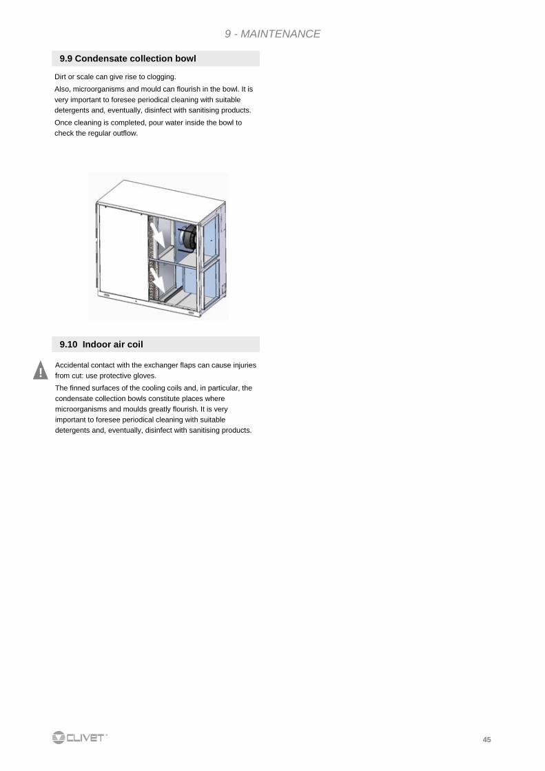
Dirt or scale can give rise to clogging.
Also, microorganisms and mould can flourish in the bowl. It is
very important to foresee periodical cleaning with suitable
detergents and, eventually, disinfect with sanitising products.
Once cleaning is completed, pour water inside the bowl to
check the regular outflow.
9.9 Condensate collection bowl
9 - MAINTENANCE
9.10 Indoor air coil
Accidental contact with the exchanger flaps can cause injuries
from cut: use protective gloves.
The finned surfaces of the cooling coils and, in particular, the
condensate collection bowls constitute places where
microorganisms and moulds greatly flourish. It is very
important to foresee periodical cleaning with suitable
detergents and, eventually, disinfect with sanitising products.
!
46
9 - MAINTENANCE
Do not use solvents or detergents to clean the plastic compo-
nents.
For descaling use a vinegar or acetic acid solution at 20%,
subsequently rinsing with water
PERIODICAL CHECKS
15 days
Cylinder:
not over 300 hours of work
checking operation, general state, no leaks
90 days
Cylinder: not over 1000 hours of work
checking operation, general state, no leaks, any
replacement
1 year
Cylinder:
not over 2500 hours of work (disposable cylinders)
Load solenoid valve replacement: disconnect
electric power supply, dismantle valve, clean the
drain solenoid valve filter:
disconnect electric power supply, remove reel and
dismantle valve body and any impurity and rinse
the power supply bowl, piping:
check they are free and without impurities
5 years
Cylinder: not over 10000 hours of work (inspectional cylinders)
replacement
HUMIDIFIER CYLINDER DRAINAGE Cylinder must be drained in these situations:
cleaning of the cylinder
emptying of the cylinder to avoid ice forming
replacement of the cylinder
The manual drainage is carried out by means of selector SA7:
see ELECTRIC CONNECTIONS chapter.
REPLACEMENT OF THE CYLINDER
To remove the cylinder: :
completely drain the water
Interrupt power supply voltage of humidifier by means of
the unit isolator
remove the vapour pipe from the cylinder
disconnect the electric connections of the electrodes and
remove the pins from the high level electrodes.
loosen the ring nut to remove the pipe unions and the filter
(when filter is outside the cylinder)
lift the cylinder to remove it
Before mounting it :
the filter body does not require replacing, wash it with
water and remount it on the new cylinder, using the new gasket provided with the latter
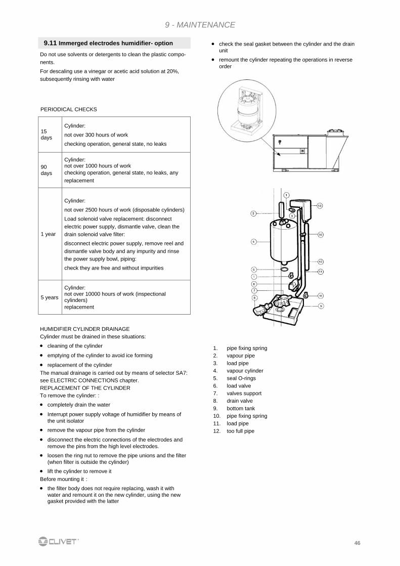
1. pipe fixing spring
2. vapour pipe
3. load pipe
4. vapour cylinder
5. seal O-rings
6. load valve
7. valves support
8. drain valve
9. bottom tank
10. pipe fixing spring
11. load pipe
12. too full pipe
9.11 Immerged electrodes humidifier- option check the seal gasket between the cylinder and the drain
unit
remount the cylinder repeating the operations in reverse
order
47
Generality
The most common situations, as they cannot be controlled by the
manufacturer, that may give rise to risk situations for things or persons
are found in this section.
Dangerous area
It is the area in which only an authorised operator can act. The
dangerous area is the area inside the unit, accessible only via removal of
the cowling or parts of it.
Handling
The handling operations, if carried out without all the necessary safety
devices and without the due caution, can cause the falling or overturning
of the unit with consequent damages, even serious, to things, persons
and the unit itself.
Handle the unit following the instructions on the packaging, in this
manual and according to the local standards in force.
In case of coolant gas leak, refer to the coolant "Safety sheet".
Installation
An incorrect installation of the unit can cause water leaks, condense
storage coolant leaks, electric shocks, fires, malfunctioning or damages
to the unit itself.
Check installation is carried out only by qualified technical personnel and
that the instructions in this manual and the local standards in force are
complied with.
The unit installation in a place where, even occasionally, the flammable
gas leaks and consequent storage of these gases in the area around the
unit itself, can cause explosions and fires.
Installation of the unit in an unsuitable place to support the weight and/or
guarantee an adequate anchoring, can cause the falling and/or
overturning, with consequent damages to things, persons or the unit
itself.
Carefully check positioning and anchoring of the unit.
The easy access to the unit by children, unauthorised persons or
animals, may give rise to accidents and injuries, even serious.
Install the unit in places accessible only by authorised personnel and/or
foresee protections against intrusions in the dangerous area.
General risks
Burnt odour, smoke or other signs of serious anomalies may show the
arising of situations that can cause damages to things, persons or the
unit itself.
Electrically isolate the unit (yellow-red isolator).
Contact the after-sales authorised assistance centre to identify and
resolve the problem at origin of the anomaly.
The accidental contact with exchange coils, compressors, supply piping
or other components can cause injuries and/or burns.
Always wear adequate clothing that includes protective gloves for
operations inside the dangerous area.
Maintenance and repair operations carried out by unqualified personnel
can cause damages to things, persons or the unit itself.
Always contact a qualified after-sales assistance centre.
The lack in closing the unit panels, or lack in checking the correct
fastening of all fastening screws of the panelling, can cause damages to
things, persons or the unit itself.
Periodically check closing of all panels and their correct fastening.
In the event of fire, the coolant temperature can reach values such to
bring the pressure over the safety value, with consequent possible
projection of coolant or explosions of the circuit that remain isolated from
closure of the cocks.
Do not stand near the safety valve and never leave the cooling system
cocks closed.
Electrical part
An incomplete connection line to the electric mains and/or with
incorrectly dimensioned cables, and/or with inadequate protective
equipment, can cause electric shocks, intoxication, damages to the unit
or fires.
Carry out all work on the electric system with reference to the wiring
diagram and this manual, assuring use of a dedicated system.
An incorrect fastening of the lid of the electric components can favour
entry of dust, water, etc. inside and consequently cause electric shocks,
damages to the unit or fires.
Always securely fasten the lid to the unit.
The metal masses of the unit, when powered and not correctly
connected to the earth system, can cause electric shocks or death for
electrocution.
Carefully execute connection to the earth system.
Contact with the accessible powered parts inside the unit after the
removal of guards can cause electric shocks, burns or death for
electrocution.
Open and padlock the main isolator before removing the guards and
signal the works in progress with relative sign.
Contact with parts that may power due to unit start-up, can cause electric
shocks, burns or death for electrocution.
When not necessary.
Moving parts
Contact with the transmissions or suction of the fans can cause injuries.
Before accessing inside the unit, open the isolator on the unit connection
line, padlock it and expose appropriate sign.
Contact with the fans can cause injuries.
Before removing the protective grilles or fans, open the isolator on the
unit connection line, padlock it and expose relative sign.
Coolant
The intervention of the safety valves and the consequent coolant gas
expulsion can cause injuries and intoxication. Always wear adequate
clothing and protective goggles for operations inside the dangerous area.
In case of coolant gas leak, refer to the coolant "Safety sheet".
Contact between naked flames or sources of heat with coolant, or the
heating of the pressurised gas circuit (e.g. during welding), can cause
explosions or fires.
Do not place any source of heat inside the dangerous area.
The maintenance or repair interventions requiring welding must be done
with system drained.
Hydraulic part
Defects in the piping, in the connections or in the shut-off parts, can
cause water leaks or projections, with consequent damages to things or
short circuits of the unit.
10 - RESIDUE RISKS
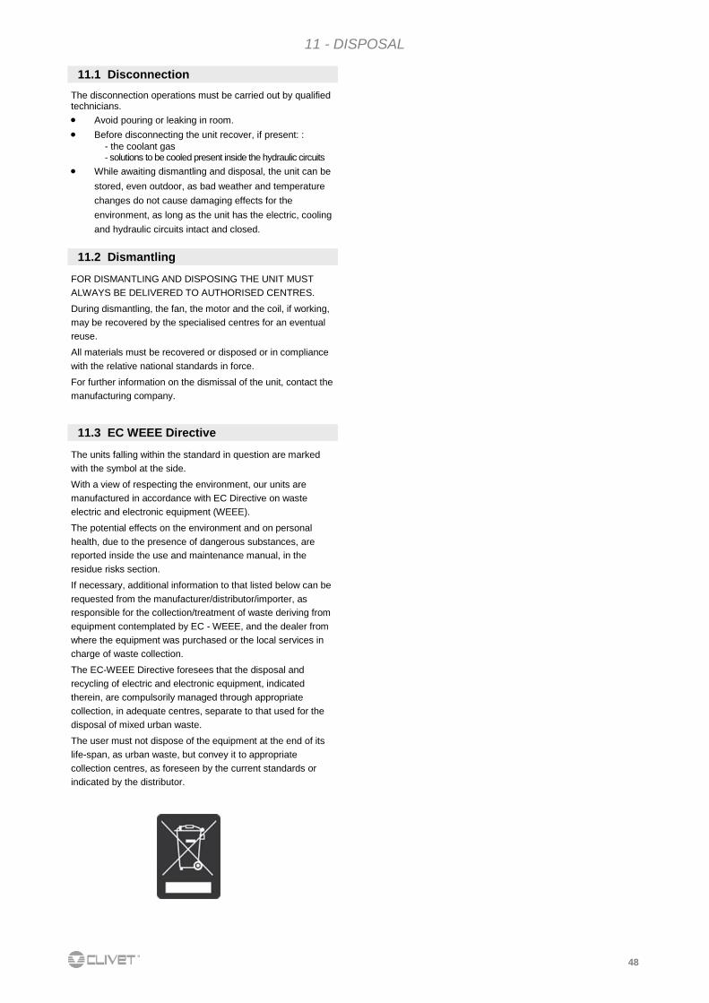
48
FOR DISMANTLING AND DISPOSING THE UNIT MUST
ALWAYS BE DELIVERED TO AUTHORISED CENTRES.
During dismantling, the fan, the motor and the coil, if working,
may be recovered by the specialised centres for an eventual
reuse.
All materials must be recovered or disposed or in compliance
with the relative national standards in force.
For further information on the dismissal of the unit, contact the
manufacturing company.
11.1 Disconnection
The disconnection operations must be carried out by qualified technicians. Avoid pouring or leaking in room.
Before disconnecting the unit recover, if present: :
- the coolant gas - solutions to be cooled present inside the hydraulic circuits
While awaiting dismantling and disposal, the unit can be
stored, even outdoor, as bad weather and temperature
changes do not cause damaging effects for the
environment, as long as the unit has the electric, cooling
and hydraulic circuits intact and closed.
The units falling within the standard in question are marked
with the symbol at the side.
With a view of respecting the environment, our units are
manufactured in accordance with EC Directive on waste
electric and electronic equipment (WEEE).
The potential effects on the environment and on personal
health, due to the presence of dangerous substances, are
reported inside the use and maintenance manual, in the
residue risks section.
If necessary, additional information to that listed below can be
requested from the manufacturer/distributor/importer, as
responsible for the collection/treatment of waste deriving from
equipment contemplated by EC - WEEE, and the dealer from
where the equipment was purchased or the local services in
charge of waste collection.
The EC-WEEE Directive foresees that the disposal and
recycling of electric and electronic equipment, indicated
therein, are compulsorily managed through appropriate
collection, in adequate centres, separate to that used for the
disposal of mixed urban waste.
The user must not dispose of the equipment at the end of its
life-span, as urban waste, but convey it to appropriate
collection centres, as foreseen by the current standards or
indicated by the distributor.
11.3 EC WEEE Directive
11.2 Dismantling
11 - DISPOSAL
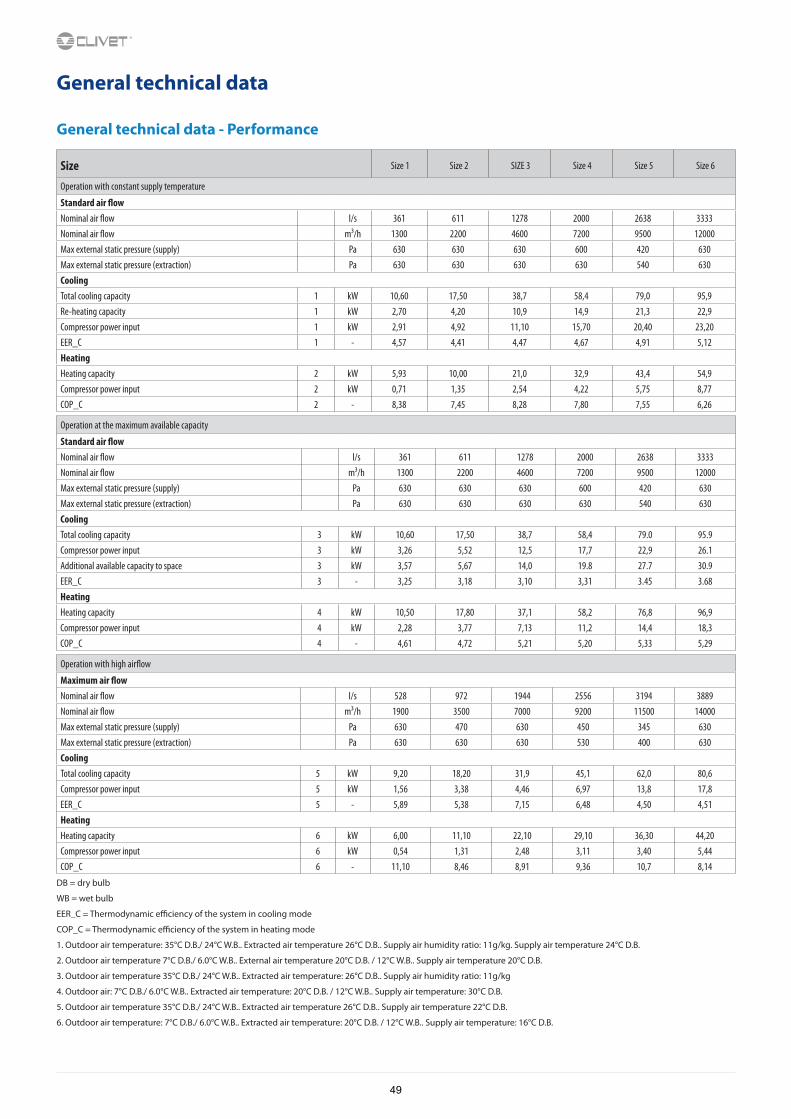
General technical data
General technical data - Performance
Size Size 1 Size 2 SIZE 3 Size 4 Size 5 Size 6
Operation with constant supply temperature
Standard air flowNominal air flow l/s 361 611 1278 2000 2638 3333Nominal air flow m³/h 1300 2200 4600 7200 9500 12000Max external static pressure (supply) Pa 630 630 630 600 420 630Max external static pressure (extraction) Pa 630 630 630 630 540 630CoolingTotal cooling capacity 1 kW 10,60 17,50 38,7 58,4 79,0 95,9Re-heating capacity 1 kW 2,70 4,20 10,9 14,9 21,3 22,9Compressor power input 1 kW 2,91 4,92 11,10 15,70 20,40 23,20EER_C 1 - 4,57 4,41 4,47 4,67 4,91 5,12HeatingHeating capacity 2 kW 5,93 10,00 21,0 32,9 43,4 54,9Compressor power input 2 kW 0,71 1,35 2,54 4,22 5,75 8,77COP_C 2 - 8,38 7,45 8,28 7,80 7,55 6,26
Operation at the maximum available capacity
Standard air flowNominal air flow l/s 361 611 1278 2000 2638 3333Nominal air flow m³/h 1300 2200 4600 7200 9500 12000Max external static pressure (supply) Pa 630 630 630 600 420 630Max external static pressure (extraction) Pa 630 630 630 630 540 630CoolingTotal cooling capacity 3 kW 10,60 17,50 38,7 58,4 79.0 95.9Compressor power input 3 kW 3,26 5,52 12,5 17,7 22,9 26.1Additional available capacity to space 3 kW 3,57 5,67 14,0 19.8 27.7 30.9EER_C 3 - 3,25 3,18 3,10 3,31 3.45 3.68HeatingHeating capacity 4 kW 10,50 17,80 37,1 58,2 76,8 96,9Compressor power input 4 kW 2,28 3,77 7,13 11,2 14,4 18,3COP_C 4 - 4,61 4,72 5,21 5,20 5,33 5,29
Operation with high airflow
Maximum air flowNominal air flow l/s 528 972 1944 2556 3194 3889Nominal air flow m³/h 1900 3500 7000 9200 11500 14000Max external static pressure (supply) Pa 630 470 630 450 345 630Max external static pressure (extraction) Pa 630 630 630 530 400 630CoolingTotal cooling capacity 5 kW 9,20 18,20 31,9 45,1 62,0 80,6Compressor power input 5 kW 1,56 3,38 4,46 6,97 13,8 17,8EER_C 5 - 5,89 5,38 7,15 6,48 4,50 4,51HeatingHeating capacity 6 kW 6,00 11,10 22,10 29,10 36,30 44,20Compressor power input 6 kW 0,54 1,31 2,48 3,11 3,40 5,44COP_C 6 - 11,10 8,46 8,91 9,36 10,7 8,14
DB = dry bulb
WB = wet bulb
EER_C = Thermodynamic efficiency of the system in cooling mode
COP_C = Thermodynamic efficiency of the system in heating mode
1. Outdoor air temperature: 35°C D.B./ 24°C W.B.. Extracted air temperature 26°C D.B.. Supply air humidity ratio: 11g/kg. Supply air temperature 24°C D.B.
2. Outdoor air temperature 7°C D.B./ 6.0°C W.B.. External air temperature 20°C D.B. / 12°C W.B.. Supply air temperature 20°C D.B.
3. Outdoor air temperature 35°C D.B./ 24°C W.B.. Extracted air temperature: 26°C D.B.. Supply air humidity ratio: 11g/kg
4. Outdoor air: 7°C D.B./ 6.0°C W.B.. Extracted air temperature: 20°C D.B. / 12°C W.B.. Supply air temperature: 30°C D.B.
5. Outdoor air temperature 35°C D.B./ 24°C W.B.. Extracted air temperature 26°C D.B.. Supply air temperature 22°C D.B.
6. Outdoor air temperature: 7°C D.B./ 6.0°C W.B.. Extracted air temperature: 20°C D.B. / 12°C W.B.. Supply air temperature: 16°C D.B.
49
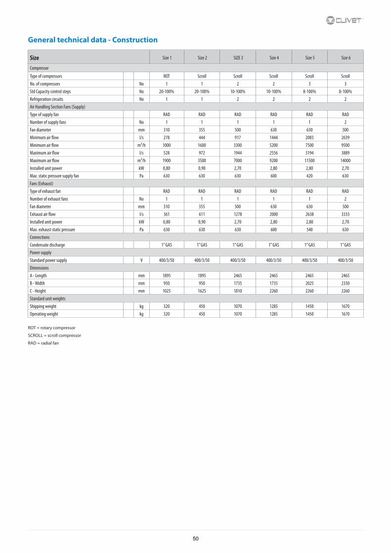
General technical data - Construction
Size Size 1 Size 2 SIZE 3 Size 4 Size 5 Size 6
Compressor
Type of compressors ROT Scroll Scroll Scroll Scroll ScrollNo. of compressors No 1 1 2 2 3 3Std Capacity control steps No 20-100% 20-100% 10-100% 10-100% 8-100% 8-100%Refrigeration circuits No 1 1 2 2 2 2Air Handling Section Fans (Supply)Type of supply fan RAD RAD RAD RAD RAD RADNumber of supply fans No 1 1 1 1 1 2Fan diameter mm 310 355 500 630 630 500Minimum air flow l/s 278 444 917 1444 2083 2639Minimum air flow m³/h 1000 1600 3300 5200 7500 9500Maximum air flow l/s 528 972 1944 2556 3194 3889Maximum air flow m³/h 1900 3500 7000 9200 11500 14000Installed unit power kW 0,80 0,90 2,70 2,80 2,80 2,70Max. static pressure supply fan Pa 630 630 630 600 420 630Fans (Exhaust)Type of exhaust fan RAD RAD RAD RAD RAD RADNumber of exhaust fans No 1 1 1 1 1 2Fan diameter mm 310 355 500 630 630 500Exhaust air flow l/s 361 611 1278 2000 2638 3333Installed unit power kW 0,80 0,90 2,70 2,80 2,80 2,70Max. exhaust static pressure Pa 630 630 630 600 540 630ConnectionsCondensate discharge 1” GAS 1” GAS 1” GAS 1” GAS 1” GAS 1” GASPower supplyStandard power supply V 400/3/50 400/3/50 400/3/50 400/3/50 400/3/50 400/3/50DimensionsA - Length mm 1895 1895 2465 2465 2465 2465B - Width mm 950 950 1735 1735 2025 2330C - Height mm 1025 1625 1810 2260 2260 2260Standard unit weightsShipping weight kg 320 450 1070 1285 1450 1670Operating weight kg 320 450 1070 1285 1450 1670
ROT = rotary compressor
SCROLL = scroll compressor
RAD = radial fan
50
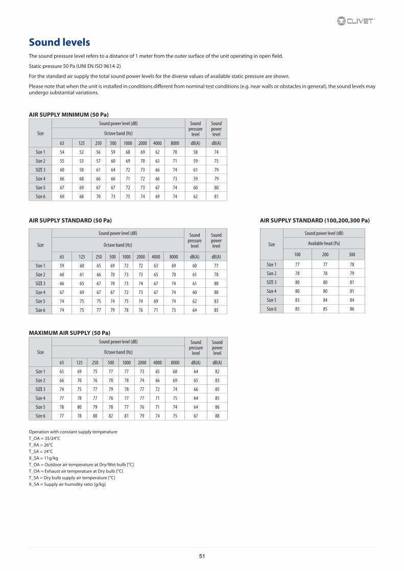
Sound levelsThe sound pressure level refers to a distance of 1 meter from the outer surface of the unit operating in open field.
Static pressure 50 Pa (UNI EN ISO 9614-2)
For the standard air supply the total sound power levels for the diverse values of available static pressure are shown.
Please note that when the unit is installed in conditions different from nominal test conditions (e.g. near walls or obstacles in general), the sound levels may undergo substantial variations.
AIR SUPPLY MINIMUM (50 Pa)
Size
Sound power level (dB) Sound pressure
level
Sound power levelOctave band (Hz)
63 125 250 500 1000 2000 4000 8000 dB(A) dB(A)
Size 1 54 52 56 59 68 69 62 70 58 74
Size 2 55 53 57 60 69 70 63 71 59 75
SIZE 3 60 58 61 64 72 73 66 74 61 79
Size 4 66 68 66 66 71 72 66 73 59 79
Size 5 67 69 67 67 72 73 67 74 60 80
Size 6 69 68 70 73 75 74 69 74 62 81
AIR SUPPLY STANDARD (50 Pa) AIR SUPPLY STANDARD (100,200,300 Pa)
Size
Sound power level (dB) Sound pressure
level
Sound power levelOctave band (Hz)
63 125 250 500 1000 2000 4000 8000 dB(A) dB(A)
Size 1 59 60 65 69 72 72 63 69 60 77
Size 2 60 61 66 70 73 73 65 70 61 78
SIZE 3 66 65 67 70 73 74 67 74 61 80
Size 4 67 69 67 67 72 73 67 74 60 80
Size 5 74 75 75 74 75 74 69 74 62 83
Size 6 74 75 77 79 78 76 71 73 64 85
Size
Sound power level (dB)
Available head (Pa)
100 200 300
Size 1 77 77 78
Size 2 78 78 79
SIZE 3 80 80 81
Size 4 80 80 81
Size 5 83 84 84
Size 6 85 85 86
MAXIMUM AIR SUPPLY (50 Pa)
Size
Sound power level (dB) Sound pressure
level
Sound power levelOctave band (Hz)
63 125 250 500 1000 2000 4000 8000 dB(A) dB(A)
Size 1 65 69 75 77 77 73 65 68 64 82
Size 2 66 70 76 78 78 74 66 69 65 83
SIZE 3 74 75 77 79 78 77 72 74 66 85
Size 4 77 78 77 76 77 77 71 75 64 85
Size 5 78 80 79 78 77 76 71 74 64 86
Size 6 77 78 80 82 81 79 74 75 67 88
Operation with constant supply temperatureT_OA = 35/24°CT_RA = 26°CT_SA = 24°CX_SA = 11g/kgT_OA = Outdoor air temperature at Dry/Wet bulb [°C]T_OA = Exhaust air temperature at Dry bulb [°C]T_SA = Dry bulb supply air temperature [°C]X_SA = Supply air humidity ratio [g/kg]
51
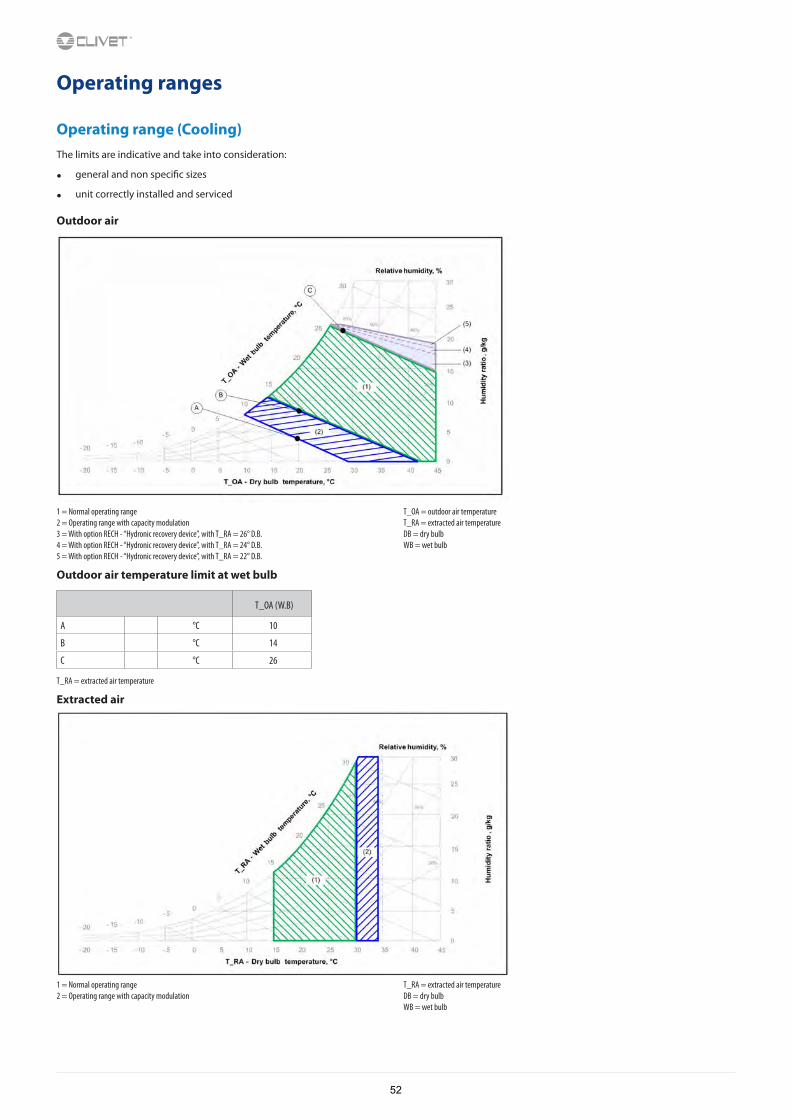
Operating ranges
Operating range (Cooling)The limits are indicative and take into consideration:
• general and non specific sizes
• unit correctly installed and serviced
Outdoor air
1 = Normal operating range2 = Operating range with capacity modulation3 = With option RECH - “Hydronic recovery device”, with T_RA = 26° D.B.4 = With option RECH - “Hydronic recovery device”, with T_RA = 24° D.B.5 = With option RECH - “Hydronic recovery device”, with T_RA = 22° D.B.
T_OA = outdoor air temperatureT_RA = extracted air temperatureDB = dry bulbWB = wet bulb
Outdoor air temperature limit at wet bulb
T_OA (W.B)
A °C 10
B °C 14
C °C 26
T_RA = extracted air temperature
Extracted air
1 = Normal operating range2 = Operating range with capacity modulation
T_RA = extracted air temperatureDB = dry bulbWB = wet bulb
52
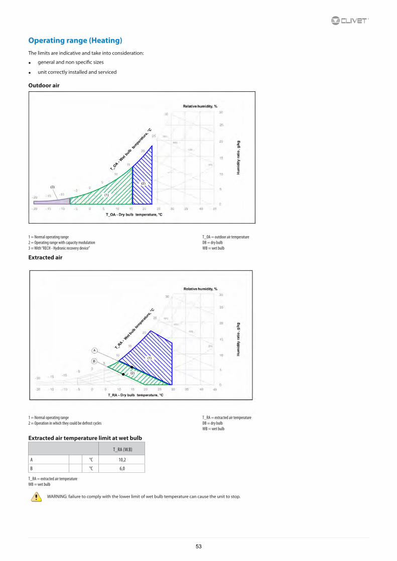
Operating range (Heating)The limits are indicative and take into consideration:
• general and non specific sizes
• unit correctly installed and serviced
Outdoor air
1 = Normal operating range2 = Operating range with capacity modulation3 = With “RECH - Hydronic recovery device”
T_OA = outdoor air temperatureDB = dry bulbWB = wet bulb
Extracted air
1 = Normal operating range2 = Operation in which they could be defrost cycles
T_RA = extracted air temperatureDB = dry bulbWB = wet bulb
Extracted air temperature limit at wet bulb
T_RA (W.B)
A °C 10,2
B °C 6,0
T_RA = extracted air temperatureWB = wet bulb
WARNING: failure to comply with the lower limit of wet bulb temperature can cause the unit to stop.
53
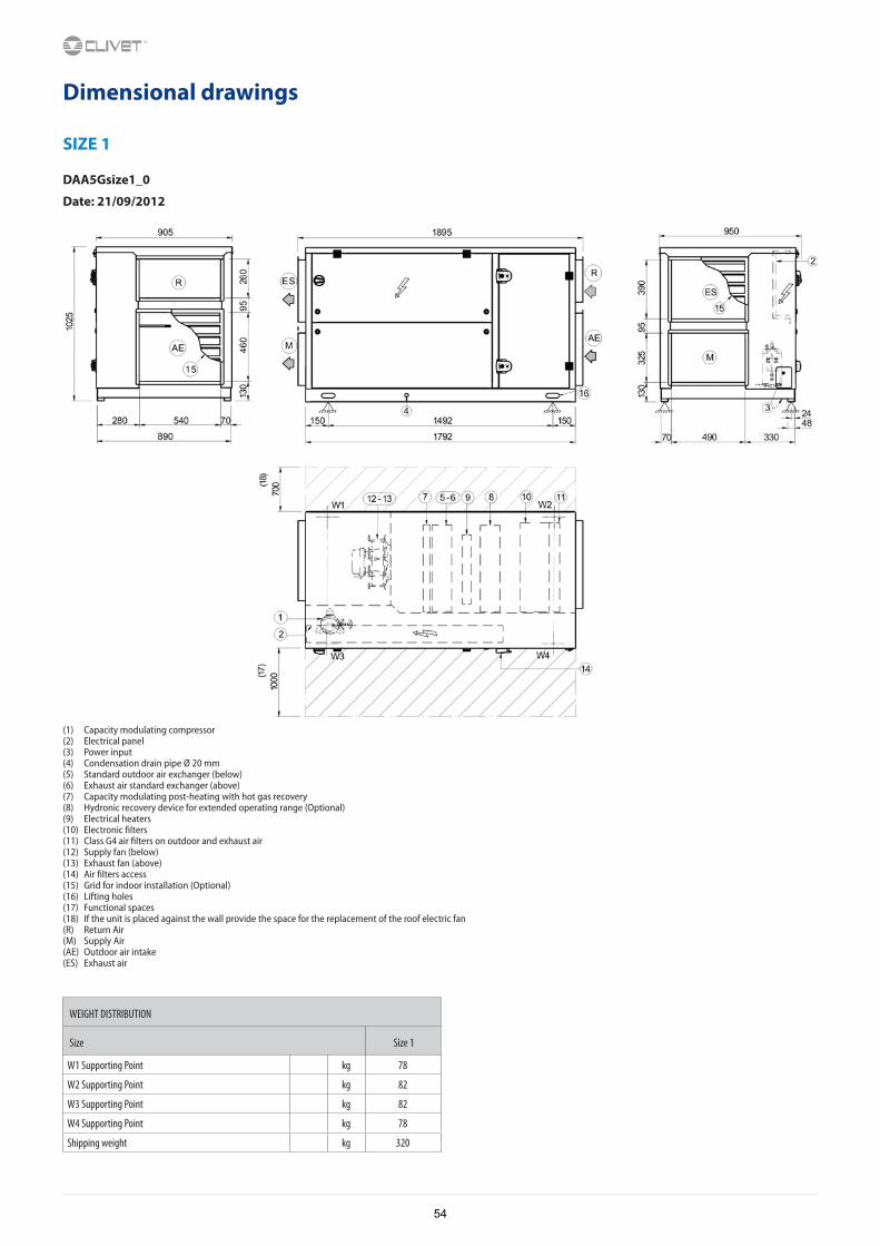
Dimensional drawings
SIZE 1
DAA5Gsize1_0
Date: 21/09/2012
(1) Capacity modulating compressor(2) Electrical panel(3) Power input(4) Condensation drain pipe Ø 20 mm(5) Standard outdoor air exchanger (below)(6) Exhaust air standard exchanger (above)(7) Capacity modulating post-heating with hot gas recovery(8) Hydronic recovery device for extended operating range (Optional)(9) Electrical heaters(10) Electronic filters(11) Class G4 air filters on outdoor and exhaust air(12) Supply fan (below)(13) Exhaust fan (above)(14) Air filters access(15) Grid for indoor installation (Optional)(16) Lifting holes(17) Functional spaces(18) If the unit is placed against the wall provide the space for the replacement of the roof electric fan(R) Return Air(M) Supply Air(AE) Outdoor air intake(ES) Exhaust air
WEIGHT DISTRIBUTION
Size Size 1
W1 Supporting Point kg 78
W2 Supporting Point kg 82
W3 Supporting Point kg 82
W4 Supporting Point kg 78
Shipping weight kg 320
54
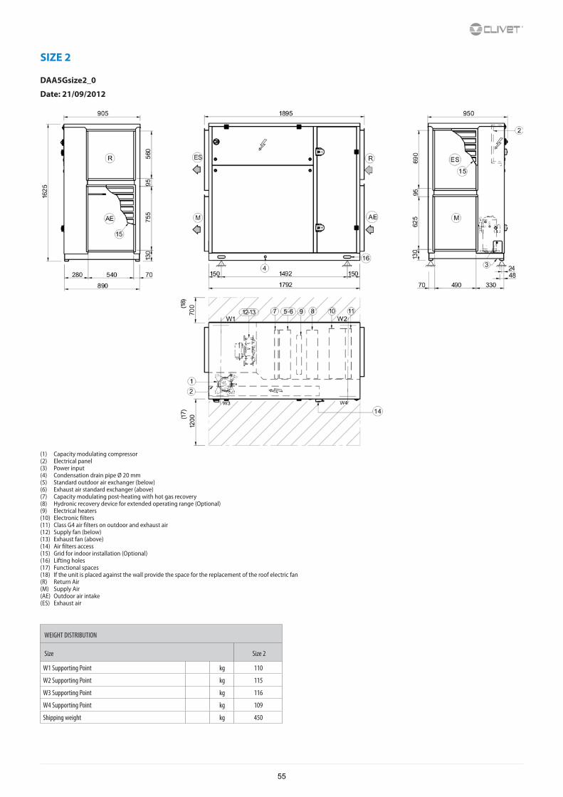
SIZE 2
DAA5Gsize2_0
Date: 21/09/2012
(1) Capacity modulating compressor(2) Electrical panel(3) Power input(4) Condensation drain pipe Ø 20 mm(5) Standard outdoor air exchanger (below)(6) Exhaust air standard exchanger (above)(7) Capacity modulating post-heating with hot gas recovery(8) Hydronic recovery device for extended operating range (Optional)(9) Electrical heaters(10) Electronic filters(11) Class G4 air filters on outdoor and exhaust air(12) Supply fan (below)(13) Exhaust fan (above)(14) Air filters access(15) Grid for indoor installation (Optional)(16) Lifting holes(17) Functional spaces(18) If the unit is placed against the wall provide the space for the replacement of the roof electric fan(R) Return Air(M) Supply Air(AE) Outdoor air intake(ES) Exhaust air
WEIGHT DISTRIBUTION
Size Size 2
W1 Supporting Point kg 110
W2 Supporting Point kg 115
W3 Supporting Point kg 116
W4 Supporting Point kg 109
Shipping weight kg 450
55
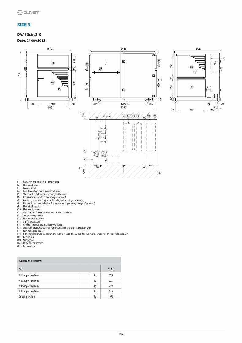
SIZE 3
DAA5Gsize3_0
Date: 21/09/2012
(1) Capacity modulating compressor(2) Electrical panel(3) Power input(4) Condensation drain pipe Ø 20 mm(5) Standard outdoor air exchanger (below)(6) Exhaust air standard exchanger (above)(7) Capacity modulating post-heating with hot gas recovery(8) Hydronic recovery device for extended operating range (Optional)(9) Electrical heaters(10) Electronic filters(11) Class G4 air filters on outdoor and exhaust air(12) Supply fan (below)(13) Exhaust fan (above)(14) Air filters access(15) Grid for indoor installation (Optional)(16) Support brackets (can be removed after the unit is positioned)(17) Functional spaces(18) If the unit is placed against the wall provide the space for the replacement of the roof electric fan(R) Return Air(M) Supply Air(AE) Outdoor air intake(ES) Exhaust air
WEIGHT DISTRIBUTION
Size SIZE 3
W1 Supporting Point kg 259
W2 Supporting Point kg 273
W3 Supporting Point kg 289
W4 Supporting Point kg 249
Shipping weight kg 1070
56
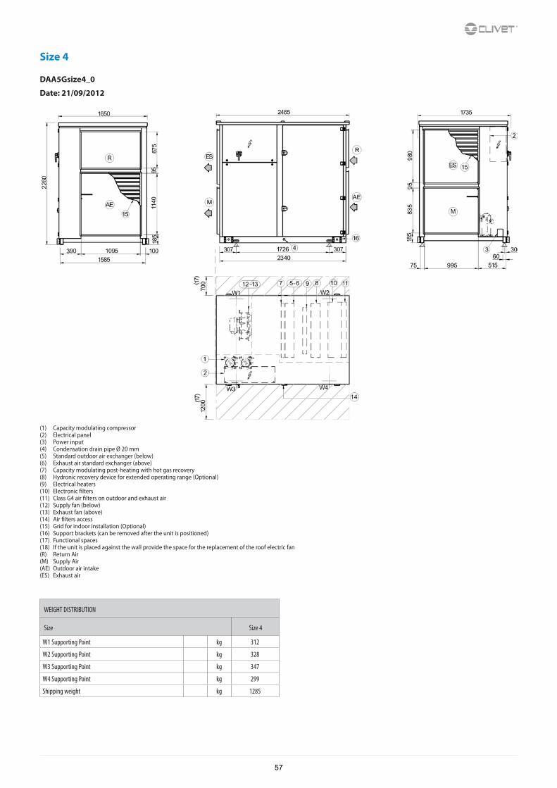
Size 4
DAA5Gsize4_0
Date: 21/09/2012
(1) Capacity modulating compressor(2) Electrical panel(3) Power input(4) Condensation drain pipe Ø 20 mm(5) Standard outdoor air exchanger (below)(6) Exhaust air standard exchanger (above)(7) Capacity modulating post-heating with hot gas recovery(8) Hydronic recovery device for extended operating range (Optional)(9) Electrical heaters(10) Electronic filters(11) Class G4 air filters on outdoor and exhaust air(12) Supply fan (below)(13) Exhaust fan (above)(14) Air filters access(15) Grid for indoor installation (Optional)(16) Support brackets (can be removed after the unit is positioned)(17) Functional spaces(18) If the unit is placed against the wall provide the space for the replacement of the roof electric fan(R) Return Air(M) Supply Air(AE) Outdoor air intake(ES) Exhaust air
WEIGHT DISTRIBUTION
Size Size 4
W1 Supporting Point kg 312
W2 Supporting Point kg 328
W3 Supporting Point kg 347
W4 Supporting Point kg 299
Shipping weight kg 1285
57
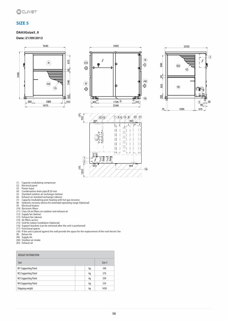
SIZE 5
DAA5Gsize5_0
Date: 21/09/2012
(1) Capacity modulating compressor(2) Electrical panel(3) Power input(4) Condensation drain pipe Ø 20 mm(5) Standard outdoor air exchanger (below)(6) Exhaust air standard exchanger (above)(7) Capacity modulating post-heating with hot gas recovery(8) Hydronic recovery device for extended operating range (Optional)(9) Electrical heaters(10) Electronic filters(11) Class G4 air filters on outdoor and exhaust air(12) Supply fan (below)(13) Exhaust fan (above)(14) Air filters access(15) Grid for indoor installation (Optional)(16) Support brackets (can be removed after the unit is positioned)(17) Functional spaces(18) If the unit is placed against the wall provide the space for the replacement of the roof electric fan(R) Return Air(M) Supply Air(AE) Outdoor air intake(ES) Exhaust air
WEIGHT DISTRIBUTION
Size Size 5
W1 Supporting Point kg 348
W2 Supporting Point kg 370
W3 Supporting Point kg 399
W4 Supporting Point kg 334
Shipping weight kg 1450
58
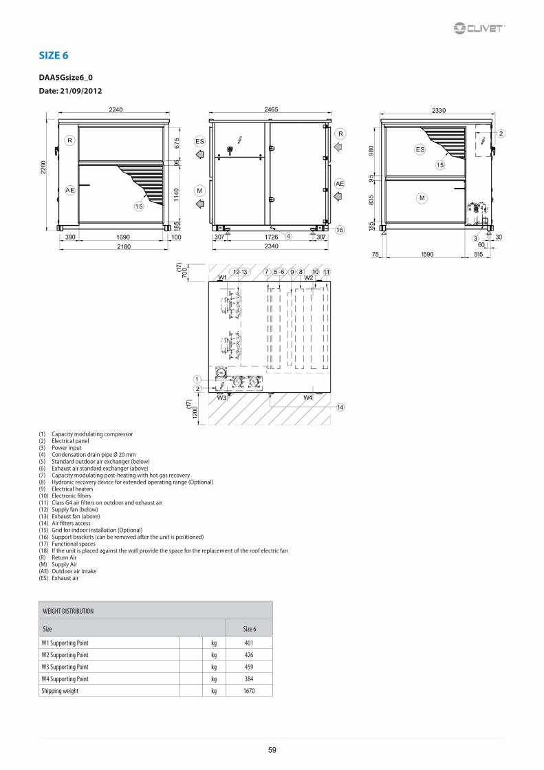
SIZE 6
DAA5Gsize6_0
Date: 21/09/2012
(1) Capacity modulating compressor(2) Electrical panel(3) Power input(4) Condensation drain pipe Ø 20 mm(5) Standard outdoor air exchanger (below)(6) Exhaust air standard exchanger (above)(7) Capacity modulating post-heating with hot gas recovery(8) Hydronic recovery device for extended operating range (Optional)(9) Electrical heaters(10) Electronic filters(11) Class G4 air filters on outdoor and exhaust air(12) Supply fan (below)(13) Exhaust fan (above)(14) Air filters access(15) Grid for indoor installation (Optional)(16) Support brackets (can be removed after the unit is positioned)(17) Functional spaces(18) If the unit is placed against the wall provide the space for the replacement of the roof electric fan(R) Return Air(M) Supply Air(AE) Outdoor air intake(ES) Exhaust air
WEIGHT DISTRIBUTION
Size Size 6
W1 Supporting Point kg 401
W2 Supporting Point kg 426
W3 Supporting Point kg 459
W4 Supporting Point kg 384
Shipping weight kg 1670
59

CLIVET SPAVia Camp Lonc 25, Z.I. Villapaiera - 32032 Feltre (BL) - Italy Tel. + 39 0439 3131 - Fax + 39 0439 313300 - [email protected]
CLIVET UK LTD (Sales)4 Kingdom Close, Segensworth East - Fareham, Hampshire - PO15 5TJ - United KingdomTel. + 44 (0) 1489 572238 - Fax + 44 (0) 1489 573033 - [email protected]
CLIVET AIRCON LTD (Service and Maintenance Division)Units F5&F6 Railway Triangle Ind Est, Walton Road - Portsmouth, Hampshire - PO6 1TG - United KingdomTel. +44 (0) 2392 381235 - Fax. +44 (0) 2392 381243 - [email protected]
CLIVET ESPAÑA COMERCIAL S.L. (Sales)Calle Gurb, 17 1º 1ª - 08500 Vic, Barcelona - EspañaTel: +34 93 8606248 - Fax +34 93 8855392 - [email protected]
CLIVET ESPAÑA S.A.U. (Service and Maintenance Division)Calle Real de Burgos Nº 12 - 28860 Paracuellos del Jarama, Madrid - EspañaTel. +34 91 6658280 - Fax +34 91 6657806 - [email protected]
CLIVET GmbHHummelsbütteler Steindamm 84, 22851 Norderstedt - GermanyTel. + 49 (0) 40 32 59 57-0 - Fax + 49 (0) 40 32 59 57-194 - [email protected]
CLIVET RUSSIA Elektrozavodskaya st. 24, office 509 - 107023, Moscow, RussiaTel. + 74956462009 - Fax + 74956462009 - [email protected]
CLIVET MIDEAST FZCODubai Silicon Oasis (DSO), High Bay Complex, Ind Unit No. 3, PO BOX 342009, Dubai, UAE Tel. + 9714 3208499 - Fax + 9714 3208216 - [email protected]
CLIVET AIRCONDITIONING SYSTEMS PRIVATE LIMITED4BA, Gundecha Onclave - Kherani Road,Saki Naka, Andheri (East) - Mumbai 400 072 - IndiaTel. +91 22 6193 7000 - Fax +91 22 6193 7001 - [email protected]
w w w . c l i v e t . c o m