cpk - hamrahsanat.com · type series booklet 2721.5/6-10 g3 cpk general member of dineniso9001...
TRANSCRIPT
Type series booklet2721.5/6-10 G3 CPK
General Member ofDIN EN ISO 9001
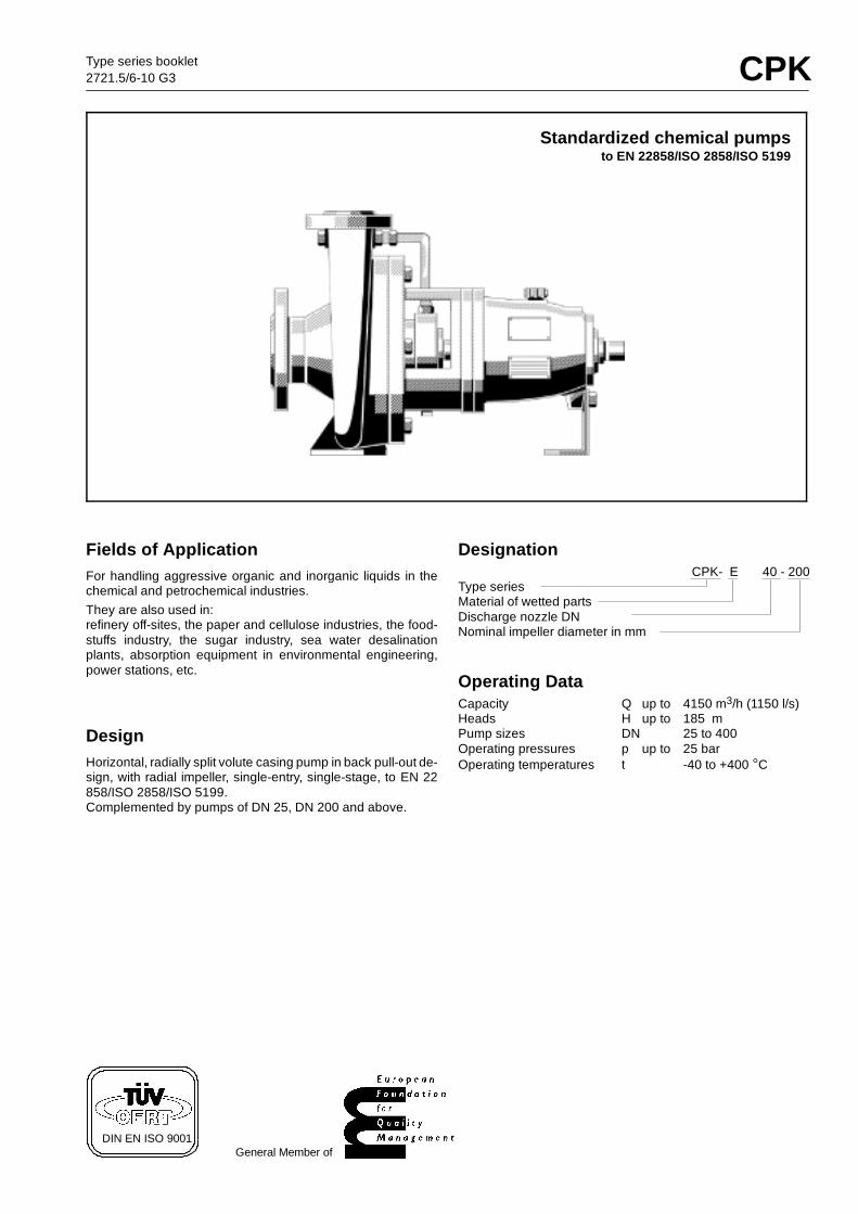
Standardized chemical pumpsto EN 22858/ISO 2858/ISO 5199
Fields of ApplicationFor handling aggressive organic and inorganic liquids in thechemical and petrochemical industries.They are also used in:refinery off-sites, the paper and cellulose industries, the food-stuffs industry, the sugar industry, sea water desalinationplants, absorption equipment in environmental engineering,power stations, etc.
DesignHorizontal, radially split volute casing pump in back pull-out de-sign, with radial impeller, single-entry, single-stage, to EN 22858/ISO 2858/ISO 5199.Complemented by pumps of DN 25, DN 200 and above.
DesignationCPK- E 40 - 200
Type seriesMaterial of wetted partsDischarge nozzle DNNominal impeller diameter in mm
Operating DataCapacity Q up to 4150 m3/h (1150 l/s)Heads H up to 185 mPump sizes DN 25 to 400Operating pressures p up to 25 barOperating temperatures t -40 to +400 C
1) 1)
1)1)
2)
CPK
2
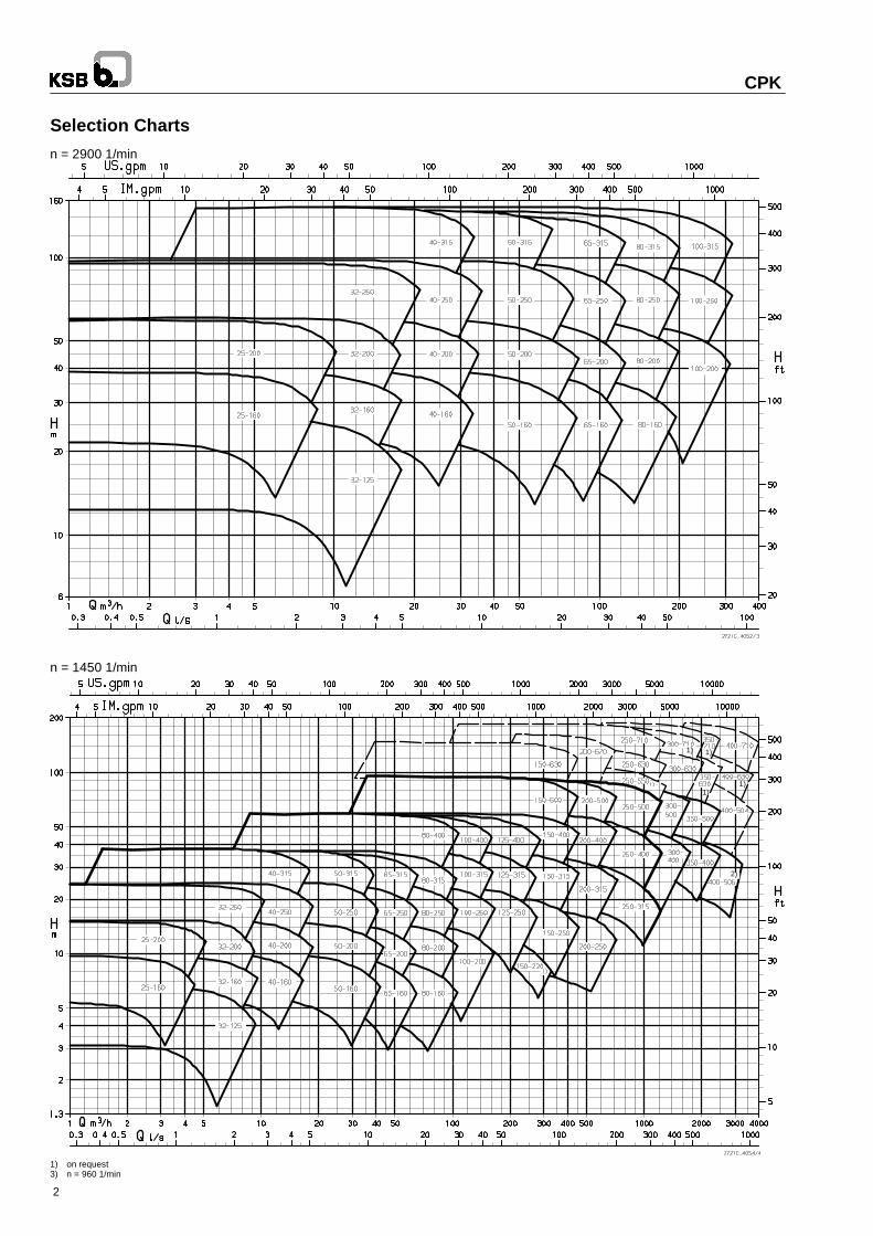
Selection Charts
n = 2900 1/min
n = 1450 1/min
1) on request3) n = 960 1/min
Per
mis
sibl
epu
mp
disc
harg
epr
essu
rein
bar
Temperature of medium handled in C
S2 pump size 150-250 and above
S2 pump sizes32-125 to 125-400
Temperature of medium handled in C
Per
mis
sibl
epu
mp
disc
harg
epr
essu
rein
bar
Temperature of medium handled in C
Per
mis
sibl
epu
mp
disc
harg
epr
essu
rein
bar
S2 pump sizes32-125 to 125-400
S2 pump size 150-250 and above
E+C3.2
C3.1
S1 +C1 +C1V
Temperature of medium handled in C
Per
mis
sibl
epu
mp
disc
harg
epr
essu
rein
bar
S2 pump size 150-250 and above
S2 pump sizes32-125 to 125-400
S1
CPK
3
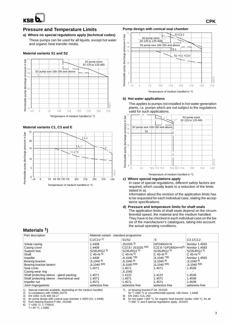
Pressure and Temperature Limitsa) Where no special regulations apply (technical codes)
These pumps can be used for all liquids, except hot waterand organic heat transfer media.
Material variants S1 and S2
Material variants C1, C3 and E
Pump design with conical seal chamber
b) Hot water applicationsThis applies to pumps not installed in hot water generationplants, i.e. pumps which are not subject to the regulationsvalid for such applications.
c) Where special regulations applyIn case of special regulations, different safety factors arerequired, which usually leads to a reduction of the limitsstated in a).Information about the revision of the application limits hasto be requested for each individual case, stating the accep-tance specifications.
d) Pressure and temperature limits for shaft sealsThe application limits of shaft seals depend on the circum-ferential speed, the material and the medium handled.They have to be checked in each individual case on the ba-sis of the manufacturer’s catalogues, taking into accountthe actual operating conditions.
Materials 1)Part description Material variant - standard programme
C1/C1V 2) S1/S2 E C3.1/C3.2Volute casingCasing coverSupport footShaftImpellerBearing bracketBearing bracket lanternSeal coverCasing wear ringShaft protecting sleeve - gland packingShaft protecting sleeve - mechanical sealImpeller nutJoint rings/gaskets
1.44081.4408S235JRG2 5)
C 45+N 6)
1.4408JL1040 8)
JL1040 8)9)
1.4571-
1.45711.45711.4571asbestos-free
JS1025 3)
C22.8 / JS1025 4)9)
S235JRG2 5)
C 45+N 6)
JL1040 7)8)
JL1040 8)
JL1040 8)9)
1.4571JL10401.41221.45711.4571asbestos-free
GP240GH+NC22.8 / GP240GH+N4)
S235JRG2 5)
C 45+N 6)
JL1040 7)8)
JL1040 8)
JL1040 8)9)
1.4571-
1.41221.45711.4571asbestos-free
Noridur 1.4593Noridur 1.4593S235JRG2 5)
C 45+N 6)
Noridur 1.4593JL1040 8)
JL1040 8)9)
1.4539-
1.45391.45391.4539asbestos-free
1) Special materials available, depending on the medium handled2) in compliance with VDMA 242763) EN 1563: GJS-400-18-LT4) for pump design with conical seal chamber 1.4593 (S1: 1.4408)5) from bearing bracket P 05s: JS10306) T >250 C: 1.7709VS
T<-40 C: 1.5680
7) on bearing bracket P 04: JS1025for T >350 C or circumferential speeds >48 m/sec: 1.4408
8) EN 1561: GJL-2509) for hot water >183 C, for organic heat transfer media >200 C, for all
T>350 C and if special regulations apply: JS1025
CPK
4
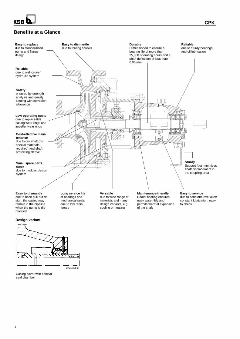
Benefits at a Glance
Easy to replacedue to standardizedpump and flangedesign
Reliabledue to well-provenhydraulic system
Safetyensured by strengthanalysis and qualitycasting with corrosionallowance
Low operating costsdue to replaceablecasing wear rings andimpeller wear rings
Easy to dismantledue to back pull-out de-sign: the casing mayremain in the pipelinewhen the pump is dis-mantled
Versatiledue to wide range ofmaterials and manydesign variants, e.g.cooling or heating
Maintenance-friendlyRadial bearing ensureseasy assembly andpermits thermal expansionof the shaft
Easy to servicedue to constant-level oiler:constant lubrication, easyto check
DurableDimensioned to ensure abearing life of more than25,000 operating hours and ashaft deflection of less than0.05 mm
Reliabledue to sturdy bearingsand oil lubrication
SturdySupport foot minimizesshaft displacement inthe coupling area
Cost-effective main-tenancedue to dry shaft (nospecial materialsrequired) and shaftprotecting sleeve
Small spare partsstockdue to modular designsystem
Long service lifeof bearings andmechanical sealsdue to low radialforces
Easy to dismantledue to forcing screws
Design variant:
Casing cover with conicalseal chamber
2721:298-2
Uni
ts
25-1
60
25-2
00
32-1
25
32-1
60
32-2
00
40-1
60
40-2
00
50-1
60
50-2
00
32-2
50
40-2
50
40-3
15
50-2
50
50-3
15
65-1
60
65-2
00
65-2
50
80-1
60
80-2
00
80-2
50
100-
200
65-3
15
80-3
15
80-4
00
100-
250
100-
315
100-
400
125-
250
125-
315
125-
400
150-
250
Uni
ts
150-
315
150-
400
150-
500
200-
250
200-
315
200-
400
200-
500
250-
315
250-
400
250-
500
150-
630
200-
670
300-
400
300-
500
350-
400
350-
500
250-
630
250-
710
300-
630
300-
710
400-
504
400-
506
350-
630
350-
710
400-
630
400-
710
CPK
5
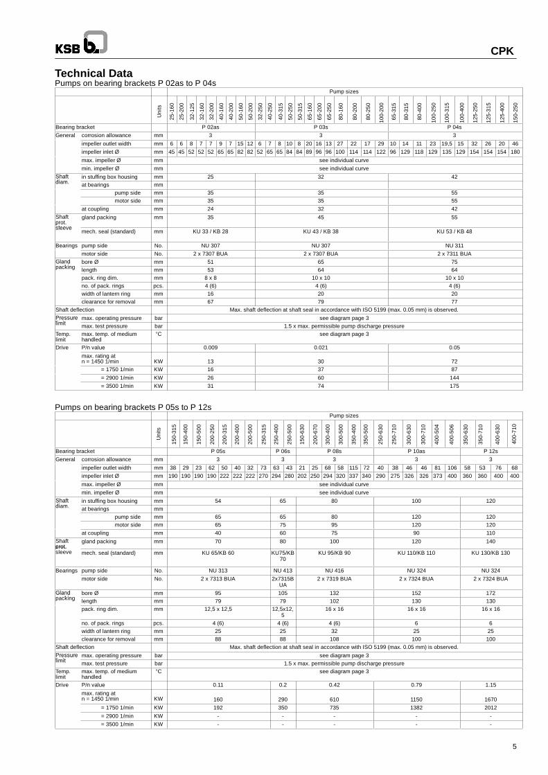
Technical DataPumps on bearing brackets P 02as to P 04s
Pump sizes
Bearing bracket P 02as P 03s P 04sGeneral corrosion allowance mm 3 3 3
impeller outlet width mm 6 6 8 7 7 9 7 15 12 6 7 8 10 8 20 16 13 27 22 17 29 10 14 11 23 19,5 15 32 26 20 46impeller inlet Ø mm 45 45 52 52 52 65 65 82 82 52 65 65 84 84 89 96 96 100 114 114 122 96 129 118 129 135 129 154 154 154 180
max. impeller Ø mm see individual curvemin. impeller Ø mm see individual curve
Shaftdiam
in stuffing box housing mm 25 32 42Shaftdiam. at bearings mm
pump side mm 35 35 55motor side mm 35 35 55
at coupling mm 24 32 42Shaftprot.sleeve
gland packing mm 35 45 55psleeve
mech. seal (standard) mm KU 33 / KB 28 KU 43 / KB 38 KU 53 / KB 48
Bearings pump side No. NU 307 NU 307 NU 311motor side No. 2 x 7307 BUA 2 x 7307 BUA 2 x 7311 BUA
Glandpacking
bore Ø mm 51 65 75Glandpacking length mm 53 64 64
pack. ring dim. mm 8 x 8 10 x 10 10 x 10no. of pack. rings pcs. 4 (6) 4 (6) 4 (6)width of lantern ring mm 16 20 20clearance for removal mm 67 79 77
Shaft deflection Max. shaft deflection at shaft seal in accordance with ISO 5199 (max. 0.05 mm) is observed.Pressurelimit
max. operating pressure bar see diagram page 3Pressurelimit max. test pressure bar 1.5 x max. permissible pump discharge pressureTemp.limit
max. temp. of mediumhandled
C see diagram page 3
Drive P/n value 0.009 0.021 0.05
max. rating atn = 1450 1/min KW 13 30 72
= 1750 1/min KW 16 37 87
= 2900 1/min KW 26 60 144= 3500 1/min KW 31 74 175
Pumps on bearing brackets P 05s to P 12sPump sizes
Bearing bracket P 05s P 06s P 08s P 10as P 12sGeneral corrosion allowance mm 3 3 3 3 3
impeller outlet width mm 38 29 23 62 50 40 32 73 63 43 21 25 68 58 115 72 40 38 46 46 81 106 58 53 76 68impeller inlet Ø mm 190 190 190 190 222 222 222 270 294 280 202 250 294 320 337 340 290 275 326 326 373 400 360 360 400 400
max. impeller Ø mm see individual curvemin. impeller Ø mm see individual curve
Shaftdiam
in stuffing box housing mm 54 65 80 100 120Shaftdiam. at bearings mm
pump side mm 65 65 80 120 120motor side mm 65 75 95 120 120
at coupling mm 40 60 75 90 110Shaftprot.
gland packing mm 70 80 100 120 140prot.sleeve mech. seal (standard) mm KU 65/KB 60 KU75/KB
70KU 95/KB 90 KU 110/KB 110 KU 130/KB 130
Bearings pump side No. NU 313 NU 413 NU 416 NU 324 NU 324motor side No. 2 x 7313 BUA 2x7315B
UA2 x 7319 BUA 2 x 7324 BUA 2 x 7324 BUA
Glandpacking
bore Ø mm 95 105 132 152 172Glandpacking length mm 79 79 102 130 130
pack. ring dim. mm 12,5 x 12,5 12,5x12,5
16 x 16 16 x 16 16 x 16
no. of pack. rings pcs. 4 (6) 4 (6) 4 (6) 6 6width of lantern ring mm 25 25 32 25 25clearance for removal mm 88 88 108 100 100
Shaft deflection Max. shaft deflection at shaft seal in accordance with ISO 5199 (max. 0.05 mm) is observed.Pressurelimit
max. operating pressure bar see diagram page 3Pressurelimit max. test pressure bar 1.5 x max. permissible pump discharge pressureTemp.limit
max. temp. of mediumhandled
C see diagram page 3
Drive P/n value 0.11 0.2 0.42 0.79 1.15
max. rating atn = 1450 1/min KW 160 290 610 1150 1670
= 1750 1/min KW 192 350 735 1382 2012
= 2900 1/min KW - - - - -= 3500 1/min KW - - - - -
2721:298-2
CPK
6
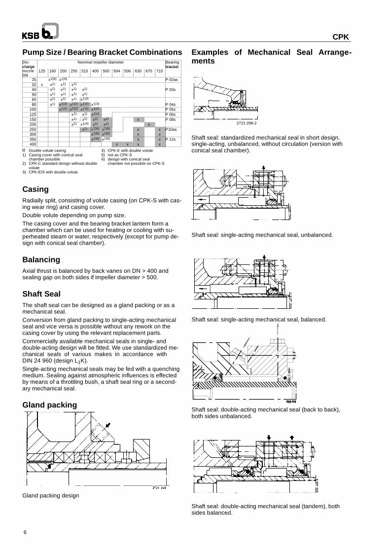
Pump Size / Bearing Bracket CombinationsDis-charge
Nominal impeller diameter Bearingbracketcharge
nozzleDN
125 160 200 250 315 400 500 504 506 630 670 710bracket
25 x1)5) x1)5) P 02as32 x x1) x1) x1)
40 x1) x1) x1) x1) P 03s50 x1) x1) x1) x1)
65 x1) x1) x1) x1)3)
80 x1) x1)2) x1)2) x1)2) x1)3) P 04s100 x1)2) x1)2) x12)) x1)2) P 05s125 x1) x1) x1)2) P 06s150 x1) x1) x1) x1) x P 08s200 x1) x1)4) x1) x1) x250 x1) x1)6) x1)6) x x P10as300 x1)6) x1)6) x x350 x1)6) x1)6) x x P 12s400 x x x x
Double volute casing 4) CPK-E with double volute1) Casing cover with conical seal 5) not as CPK-S
chamber possible 6) design with conical seal2) CPK-C standard design without double chamber not possible on CPK-S
volute3) CPK-E/S with double volute
CasingRadially split, consisting of volute casing (on CPK-S with cas-ing wear ring) and casing cover.Double volute depending on pump size.The casing cover and the bearing bracket lantern form achamber which can be used for heating or cooling with su-perheated steam or water, respectively (except for pump de-sign with conical seal chamber).
BalancingAxial thrust is balanced by back vanes on DN > 400 andsealing gap on both sides if impeller diameter > 500.
Shaft SealThe shaft seal can be designed as a gland packing or as amechanical seal.Conversion from gland packing to single-acting mechanicalseal and vice versa is possible without any rework on thecasing cover by using the relevant replacement parts.Commercially available mechanical seals in single- anddouble-acting design will be fitted. We use standardized me-chanical seals of various makes in accordance withDIN 24 960 (design L1K).Single-acting mechanical seals may be fed with a quenchingmedium. Sealing against atmospheric influences is effectedby means of a throttling bush, a shaft seal ring or a second-ary mechanical seal.
Gland packing
Gland packing design
Examples of Mechanical Seal Arrange-ments
Shaft seal: standardized mechanical seal in short design,single-acting, unbalanced, without circulation (version withconical seal chamber).
Shaft seal: single-acting mechanical seal, unbalanced.
Shaft seal: single-acting mechanical seal, balanced.
Shaft seal: double-acting mechanical seal (back to back),both sides unbalanced.
Shaft seal: double-acting mechanical seal (tandem), bothsides balanced.
NN
00
17
17
UU
NN
17
17
17
WW
Mec
hani
cals
eal
CPK
7
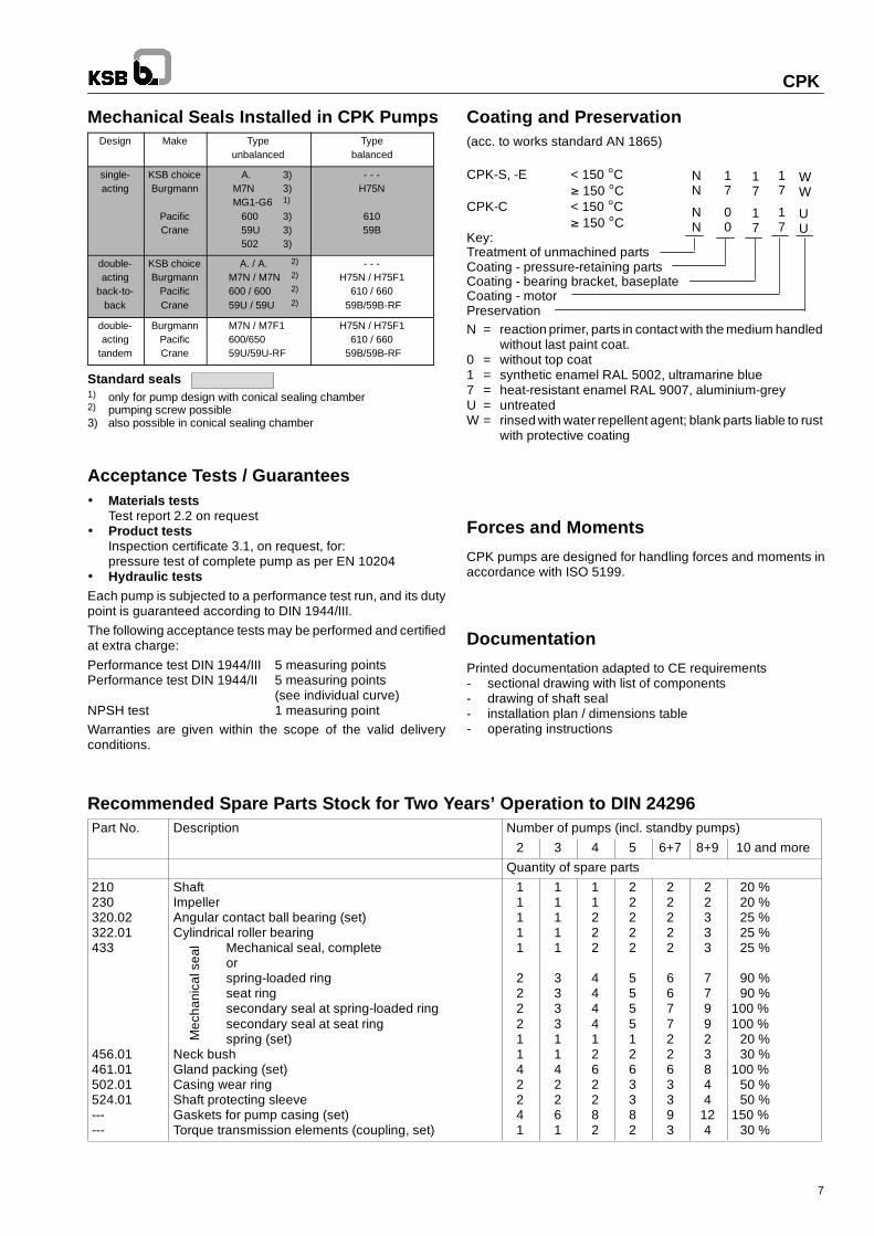
Mechanical Seals Installed in CPK PumpsDesign Make Type
unbalancedType
balanced
single-acting
KSB choiceBurgmann
PacificCrane
A. 3)M7N 3)MG1-G6 1)
600 3)59U 3)502 3)
- - -H75N
61059B
double-acting
back-to-back
KSB choiceBurgmann
PacificCrane
A. / A. 2)
M7N / M7N 2)
600 / 600 2)
59U / 59U 2)
- - -H75N / H75F1
610 / 66059B/59B-RF
double-acting
tandem
BurgmannPacificCrane
M7N / M7F1600/65059U/59U-RF
H75N / H75F1610 / 660
59B/59B-RF
Standard seals1) only for pump design with conical sealing chamber2) pumping screw possible3) also possible in conical sealing chamber
Acceptance Tests / Guarantees Materials tests
Test report 2.2 on request Product tests
Inspection certificate 3.1, on request, for:pressure test of complete pump as per EN 10204
Hydraulic testsEach pump is subjected to a performance test run, and its dutypoint is guaranteed according to DIN 1944/III.The following acceptance tests may be performed and certifiedat extra charge:Performance test DIN 1944/III 5 measuring pointsPerformance test DIN 1944/II 5 measuring points
(see individual curve)NPSH test 1 measuring pointWarranties are given within the scope of the valid deliveryconditions.
Coating and Preservation(acc. to works standard AN 1865)
CPK-S, -E < 150 C∫ 150 C
CPK-C < 150 C∫ 150 C
Key:Treatment of unmachined partsCoating - pressure-retaining partsCoating - bearing bracket, baseplateCoating - motorPreservationN = reaction primer, parts in contact with the medium handled
without last paint coat.0 = without top coat1 = synthetic enamel RAL 5002, ultramarine blue7 = heat-resistant enamel RAL 9007, aluminium-greyU = untreatedW = rinsed with water repellent agent; blank parts liable to rust
with protective coating
Forces and Moments
CPK pumps are designed for handling forces and moments inaccordance with ISO 5199.
Documentation
Printed documentation adapted to CE requirements- sectional drawing with list of components- drawing of shaft seal- installation plan / dimensions table- operating instructions
Recommended Spare Parts Stock for Two Years’ Operation to DIN 24296Part No. Description Number of pumps (incl. standby pumps)
2 3 4 5 6+7 8+9 10 and more
Quantity of spare parts
210230320.02322.01433
456.01461.01502.01524.01------
ShaftImpellerAngular contact ball bearing (set)Cylindrical roller bearing
Mechanical seal, completeorspring-loaded ringseat ringsecondary seal at spring-loaded ringsecondary seal at seat ringspring (set)
Neck bushGland packing (set)Casing wear ringShaft protecting sleeveGaskets for pump casing (set)Torque transmission elements (coupling, set)
11111
22221142241
11111
33331142261
11222
44441262282
22222
55551263382
22222
66772263393
22333
779923844
124
20 %20 %25 %25 %25 %
90 %90 %
100 %100 %
20 %30 %
100 %50 %50 %
150 %30 %
CPK-S1
CPK-C1/C1V
CPK-C3.2
CPK-C3.1
CPK-S2
CPK-E
EN1092-2 , PN 16 2)
DIN 2543, PN 16
DIN 2544, PN 25
DIN 2543, PN 16
EN1092-2, PN 25
DIN 2544, PN 25
Flange design
2) drilled
CPK
8
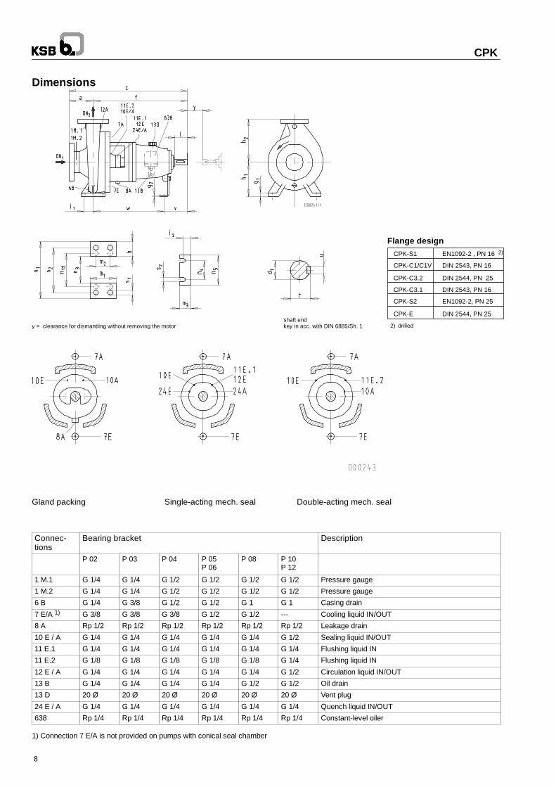
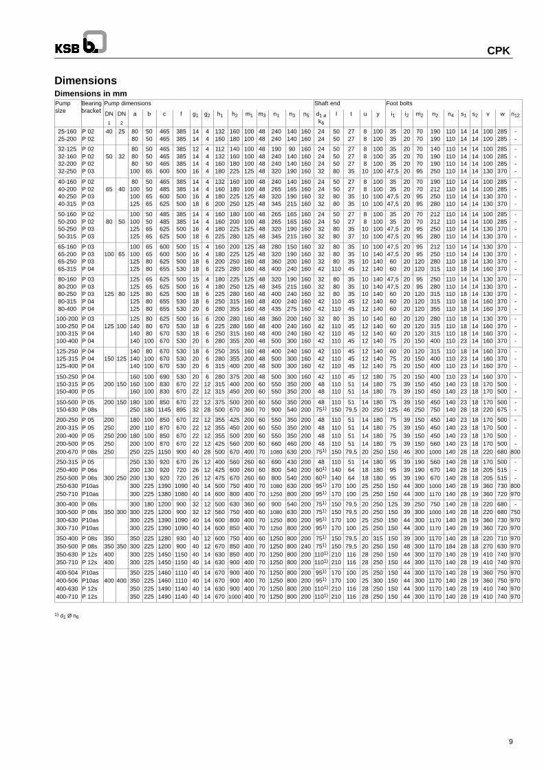
Dimensions
shaft endy = clearance for dismantling without removing the motor key in acc. with DIN 6885/Sh. 1
Gland packing Single-acting mech. seal Double-acting mech. seal
Connec-tions
Bearing bracket Description
P 02 P 03 P 04 P 05P 06
P 08 P 10P 12
1 M.1 G 1/4 G 1/4 G 1/2 G 1/2 G 1/2 G 1/2 Pressure gauge
1 M.2 G 1/4 G 1/4 G 1/2 G 1/2 G 1/2 G 1/2 Pressure gauge
6 B G 1/4 G 3/8 G 1/2 G 1/2 G 1 G 1 Casing drain
7 E/A 1) G 3/8 G 3/8 G 3/8 G 1/2 G 1/2 --- Cooling liquid IN/OUT
8 A Rp 1/2 Rp 1/2 Rp 1/2 Rp 1/2 Rp 1/2 Rp 1/2 Leakage drain
10 E / A G 1/4 G 1/4 G 1/4 G 1/4 G 1/4 G 1/2 Sealing liquid IN/OUT
11 E.1 G 1/4 G 1/4 G 1/4 G 1/4 G 1/4 G 1/4 Flushing liquid IN
11 E.2 G 1/8 G 1/8 G 1/8 G 1/8 G 1/8 G 1/4 Flushing liquid IN
12 E / A G 1/4 G 1/4 G 1/4 G 1/4 G 1/4 G 1/2 Circulation liquid IN/OUT
13 B G 1/4 G 1/4 G 1/4 G 1/4 G 1/2 G 1/2 Oil drain
13 D 20 Ø 20 Ø 20 Ø 20 Ø 20 Ø 20 Ø Vent plug
24 E / A G 1/4 G 1/4 G 1/4 G 1/4 G 1/4 G 1/4 Quench liquid IN/OUT
638 Rp 1/4 Rp 1/4 Rp 1/4 Rp 1/4 Rp 1/4 Rp 1/4 Constant-level oiler
1) Connection 7 E/A is not provided on pumps with conical seal chamber
CPK
9
DimensionsDimensions in mmPumpi
Bearingb k t
Pump dimensions Shaft end Foot boltssize bracket DN
1
DN2
a b c f g1 g2 h1 h2 m1 m3 n1 n3 n5 d1 øk6
l t u y i1 i2 m2 n2 n4 s1 s2 v w n12
25-16025-200
P 02P 02
40 25 8080
5050
465465
385385
1414
44
132160
160180
100100
4848
240240
140140
160160
2424
5050
2727
88
100100
3535
2020
7070
190190
110110
1414
1414
100100
285285
--
32-12532-16032-20032-250
P 02P 02P 02P 03
50 32808080
100
50505065
465465465600
385385385500
12141416
4444
112132160180
140160180225
100100100125
48484848
190240240320
90140140190
160160160160
24242432
50505080
27272735
888
10
100100100100
353535
47,5
20202020
70707095
140190190250
110110110110
14141414
14141414
100100100130
285285285370
----
40-16040-20040-25040-315
P 02P 02P 03P 03
65 4080
100100125
50506565
465485600625
385385500500
14141618
4446
132160180200
160180225250
100100125125
48484848
240265320345
140165190215
160160160160
24243232
50508080
27273535
88
1010
100100100100
3535
47,547,5
20202020
70709595
190212250280
110110110110
14141414
14141414
100100130130
285285370370
----
50-16050-20050-25050-315
P 02P 02P 03P 03
80 50100100125125
50506565
485485625625
385385500500
14141618
4446
160160180225
180200225280
100100125125
48484848
265265320345
165165190215
160160160160
24243232
50508080
27273537
88
1010
100100100100
3535
47,547,5
20202020
70709595
212212250280
110110110110
14141414
14141414
100100130130
285285370370
----
65-16065-20065-25065-315
P 03P 03P 03P 04
100 65100100125125
65658080
600600625655
500500500530
15161818
4466
160180200225
200225250280
125125160160
48484848
280320360400
150190200240
160160160160
32323242
808080110
35353545
10101012
100140140140
47,547,56060
20202020
9595
120120
212250280315
110110110110
14141818
14141414
130130130160
370370370370
----
80-16080-20080-25080-31580-400
P 03P 03P 03P 04P 04
125 80
125125125125125
6565808080
625625625655655
500500500530530
1516181820
44666
180180225250280
225250280315355
125125160160160
4848484848
320345400400435
190215240240275
160160160160160
3232324242
808080110110
3535354545
1010101212
140140140140140
47,547,5606060
2020202020
9595
120120120
250280315315355
110110110110110
1414181818
1414141414
130130130160160
370370370370370
-----
100-200100-250100-315100-400
P 03P 04P 04P 04
125 100125140140140
808080
100
625670670670
500530530530
16181820
6666
200225250280
280280315355
160160160200
48484848
360400400500
200240240300
160160160160
32424242
80110110110
35454545
10121212
140140140140
60606075
20202020
120120120150
280315315400
110110110110
18181823
14141414
130160160160
370370370370
----
125-250125-315125-400
P 04P 04P 04
150 125140140140
80100100
670670670
530530530
182020
666
250280315
355355400
160200200
484848
400500500
240300300
160160160
424242
110110110
454545
121212
140140140
607575
202020
120150150
315400400
110110110
182323
141414
160160160
370370370
---
150-250150-315150-400
P 04P 05P 05
200 150160160160
100100100
690830830
530670670
202222
61212
280315315
375400450
200200200
486060
500550550
300350350
160200200
424848
110110110
455151
121414
180180180
757575
203939
150150150
400450450
110140140
232323
141818
160170170
370500500
---
150-500150-630
P 05P 08s
200 150 180250
100180
8501145
670895
2232
1228
375500
500670
200360
6070
550900
350540
200200
48751)
110150
5179,5
1420
180250
75125
3946
150250
450750
140140
2328
1818
170220
500675
--
200-250200-315200-400200-500200-670
P 05P 05P 05P 05P 08s
200250250250250
200
180200180200250
100110100100225
8508708508701150
670670670670900
2222222240
1212121228
355355355425500
425450500560670
200200200200400
6060606070
5505505506601080
350350350460630
200200200200200
48484848
751)
110110110110150
51515151
79,5
1414141420
180180180180250
75757575
150
3939393946
150150150150300
4504504505601000
140140140140140
2323232328
1818181818
170170170170220
500500500500680
----
800
250-315250-400250-500250-630250-710
P 05P 06sP 06sP10asP10as
300 250
250200200300300
130130130225225
920920920
13901380
670720720
10901080
2626264040
1212121414
400425475500600
560600670750800
260260260400400
6060607070
69080080010801250
430540540630800
200200200200200
48601)
601)
951)
951)
110140140170170
516464
100100
1418182525
180180180250250
959595
150150
3939394444
190190190300300
56067067010001170
140140140140140
2828282828
1818181919
170205205360360
500515515730720
---
800970
300-400300-500300-630300-710
P 08sP 08sP10asP10as
350 300300300300300
180225225225
1200120013901390
900900
10901090
32324040
12121414
500560600600
630750800850
360400400400
60607070
900108012501250
540630800800
200200200200
751)
751)
951)
951)
150150170170
79,579,5100100
20202525
250250250250
125150150150
39394444
250300300300
750100011701170
140140140140
28282828
18181919
220220360360
680680730720
-750970970
350-400350-500350-630350-710
P 08sP 08sP 12sP 12s
350350400400
350350300300300
225225225225
1280120014501450
93090011501150
40404040
12121414
600670630630
750850850900
400400400400
60707070
1250125012501250
800800800800
200240200200
751)
751)
1101)
1101)
150150210210
79,579,5116116
20202828
315250250250
150150150150
39484444
300300300300
1170117011701170
140184140140
28282828
18181919
220270410410
710630740740
970970970970
400-504400-506400-630400-710
P10asP10asP 12sP 12s
400 400350350350350
225225225225
1460146014901490
1110111011401140
40404040
14141414
670670630670
9009009001000
400400400400
70707070
1250125012501250
800800800800
200200200200
951)
951)
1101)
1101)
170170210210
100100116116
25252828
250300250250
150150150150
44444444
300300300300
1170117011701170
140140140140
28282828
19191919
360360410410
750750740740
970970970970
1) d1 Ø n6
Gla
ndpa
ckin
gva
riant
CPK
10
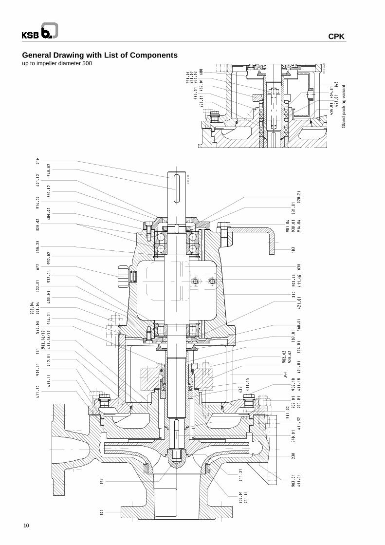
General Drawing with List of Componentsup to impeller diameter 500
CP
KWhen ordering spare parts please always specify the type series/pump size, works No. (stamped on the name plate and on the suctionnozzle flange), motor No. (serial No.), year of construction, quantityrequired, part No., descripton, material, medium handled, sectionaldrawing No. and mode of dispatch.
11
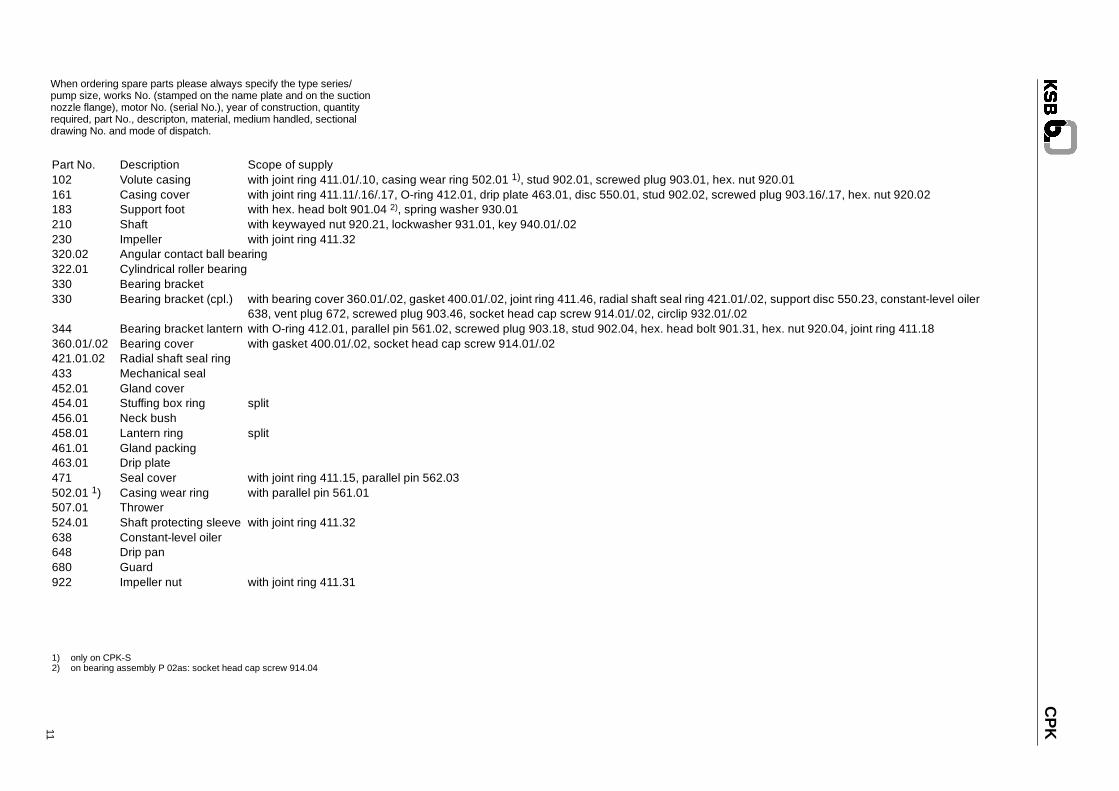
Part No. Description Scope of supply102 Volute casing with joint ring 411.01/.10, casing wear ring 502.01 1), stud 902.01, screwed plug 903.01, hex. nut 920.01161 Casing cover with joint ring 411.11/.16/.17, O-ring 412.01, drip plate 463.01, disc 550.01, stud 902.02, screwed plug 903.16/.17, hex. nut 920.02183 Support foot with hex. head bolt 901.04 2), spring washer 930.01210 Shaft with keywayed nut 920.21, lockwasher 931.01, key 940.01/.02230 Impeller with joint ring 411.32320.02 Angular contact ball bearing322.01 Cylindrical roller bearing330 Bearing bracket330 Bearing bracket (cpl.) with bearing cover 360.01/.02, gasket 400.01/.02, joint ring 411.46, radial shaft seal ring 421.01/.02, support disc 550.23, constant-level oiler
638, vent plug 672, screwed plug 903.46, socket head cap screw 914.01/.02, circlip 932.01/.02344 Bearing bracket lantern with O-ring 412.01, parallel pin 561.02, screwed plug 903.18, stud 902.04, hex. head bolt 901.31, hex. nut 920.04, joint ring 411.18360.01/.02 Bearing cover with gasket 400.01/.02, socket head cap screw 914.01/.02421.01.02 Radial shaft seal ring433 Mechanical seal452.01 Gland cover454.01 Stuffing box ring split456.01 Neck bush458.01 Lantern ring split461.01 Gland packing463.01 Drip plate471 Seal cover with joint ring 411.15, parallel pin 562.03502.01 1) Casing wear ring with parallel pin 561.01507.01 Thrower524.01 Shaft protecting sleeve with joint ring 411.32638 Constant-level oiler648 Drip pan680 Guard922 Impeller nut with joint ring 411.31
1) only on CPK-S2) on bearing assembly P 02as: socket head cap screw 914.04
Impe
ller
conn
ectio
non
P08
s
CPK
12
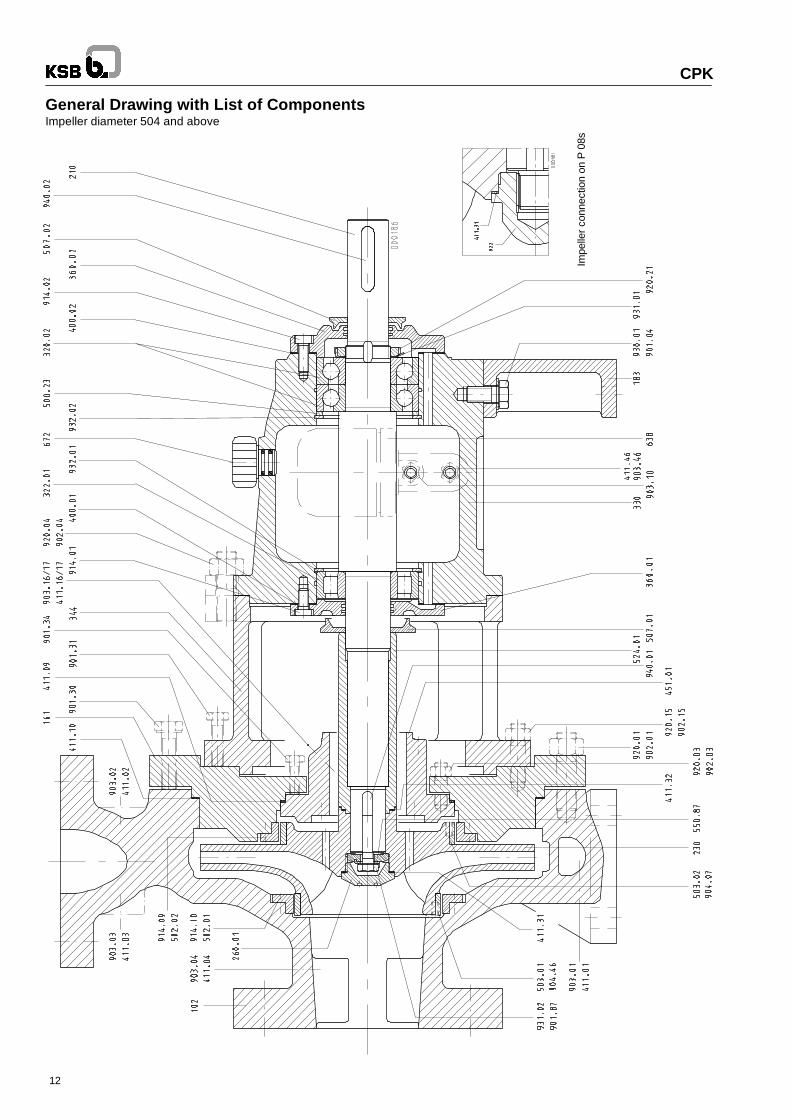
General Drawing with List of ComponentsImpeller diameter 504 and above
CP
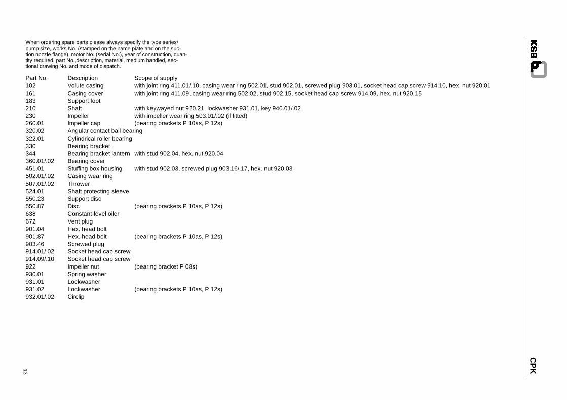
KWhen ordering spare parts please always specify the type series/pump size, works No. (stamped on the name plate and on the suc-tion nozzle flange), motor No. (serial No.), year of construction, quan-tity required, part No.,description, material, medium handled, sec-tional drawing No. and mode of dispatch.
13
Part No. Description Scope of supply102 Volute casing with joint ring 411.01/.10, casing wear ring 502.01, stud 902.01, screwed plug 903.01, socket head cap screw 914.10, hex. nut 920.01161 Casing cover with joint ring 411.09, casing wear ring 502.02, stud 902.15, socket head cap screw 914.09, hex. nut 920.15183 Support foot210 Shaft with keywayed nut 920.21, lockwasher 931.01, key 940.01/.02230 Impeller with impeller wear ring 503.01/.02 (if fitted)260.01 Impeller cap (bearing brackets P 10as, P 12s)320.02 Angular contact ball bearing322.01 Cylindrical roller bearing330 Bearing bracket344 Bearing bracket lantern with stud 902.04, hex. nut 920.04360.01/.02 Bearing cover451.01 Stuffing box housing with stud 902.03, screwed plug 903.16/.17, hex. nut 920.03502.01/.02 Casing wear ring507.01/.02 Thrower524.01 Shaft protecting sleeve550.23 Support disc550.87 Disc (bearing brackets P 10as, P 12s)638 Constant-level oiler672 Vent plug901.04 Hex. head bolt901.87 Hex. head bolt (bearing brackets P 10as, P 12s)903.46 Screwed plug914.01/.02 Socket head cap screw914.09/.10 Socket head cap screw922 Impeller nut (bearing bracket P 08s)930.01 Spring washer931.01 Lockwasher931.02 Lockwasher (bearing brackets P 10as, P 12s)932.01/.02 Circlip
CPK
14
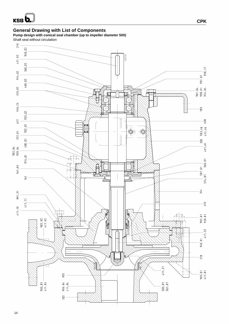
General Drawing with List of ComponentsPump design with conical seal chamber (up to impeller diameter 500)Shaft seal without circulation
CP
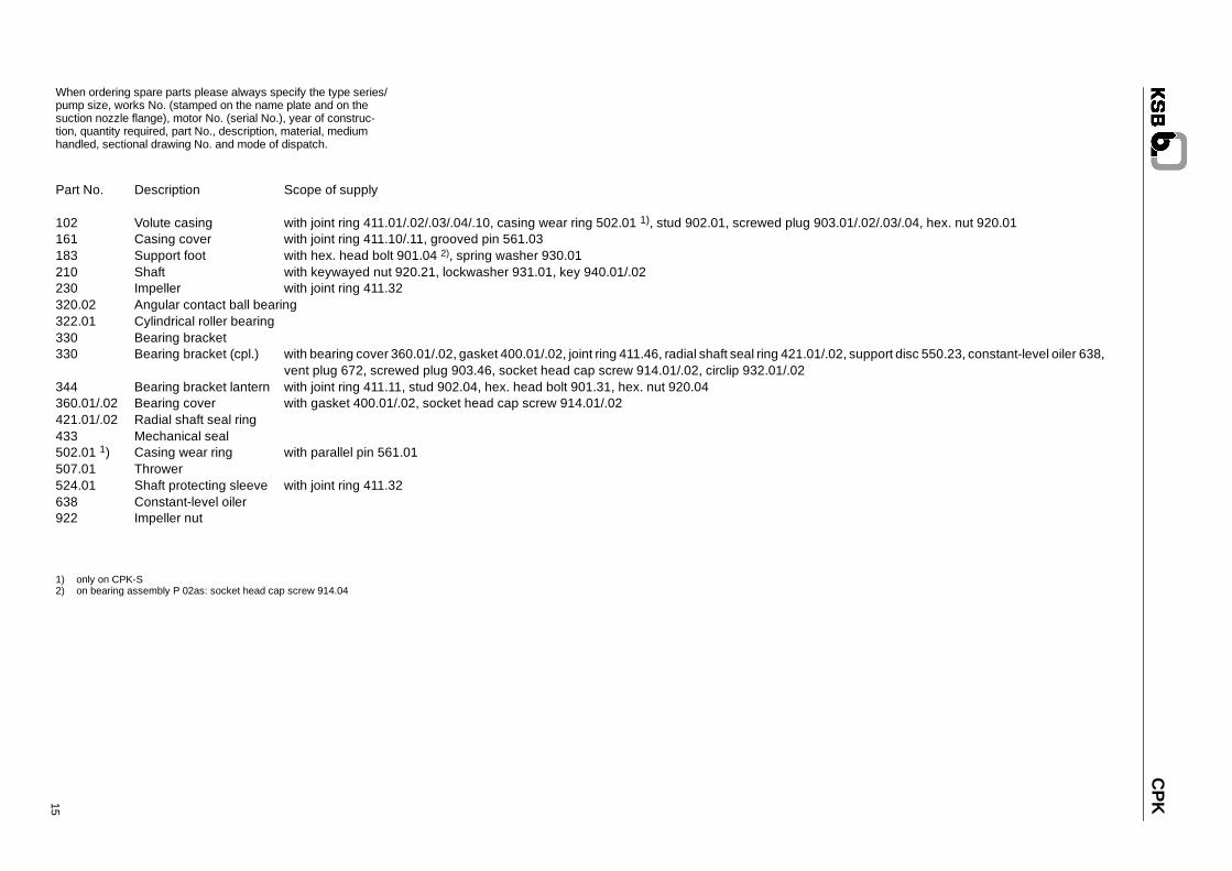
KWhen ordering spare parts please always specify the type series/pump size, works No. (stamped on the name plate and on thesuction nozzle flange), motor No. (serial No.), year of construc-tion, quantity required, part No., description, material, mediumhandled, sectional drawing No. and mode of dispatch.
15
1) only on CPK-S2) on bearing assembly P 02as: socket head cap screw 914.04
Part No. Description Scope of supply
102 Volute casing with joint ring 411.01/.02/.03/.04/.10, casing wear ring 502.01 1), stud 902.01, screwed plug 903.01/.02/.03/.04, hex. nut 920.01161 Casing cover with joint ring 411.10/.11, grooved pin 561.03183 Support foot with hex. head bolt 901.04 2), spring washer 930.01210 Shaft with keywayed nut 920.21, lockwasher 931.01, key 940.01/.02230 Impeller with joint ring 411.32320.02 Angular contact ball bearing322.01 Cylindrical roller bearing330 Bearing bracket330 Bearing bracket (cpl.) with bearing cover 360.01/.02, gasket 400.01/.02, joint ring 411.46, radial shaft seal ring 421.01/.02, support disc 550.23, constant-level oiler 638,
vent plug 672, screwed plug 903.46, socket head cap screw 914.01/.02, circlip 932.01/.02344 Bearing bracket lantern with joint ring 411.11, stud 902.04, hex. head bolt 901.31, hex. nut 920.04360.01/.02 Bearing cover with gasket 400.01/.02, socket head cap screw 914.01/.02421.01/.02 Radial shaft seal ring433 Mechanical seal502.01 1) Casing wear ring with parallel pin 561.01507.01 Thrower524.01 Shaft protecting sleeve with joint ring 411.32638 Constant-level oiler922 Impeller nut
15.8
.200
0X
BS
Sub
ject
tote
chni
calm
odifi
catio
ns.
d/7
CPK
KSB AktiengesellschaftP.O. Box 1361, 91253 Pegnitz . Bahnhofplatz 1, 91257 Pegnitz (Germany)Tel.: (+49) 92 41/71-0 . Fax: (+49) 92 41/71 17 91 . www.ksb-industry.com