cpls drip-proof 3-phase induction motors - leroy- · pdf filedrip-proof 3-phase induction...
TRANSCRIPT
CPLS
Drip-proof 3-phase induction motors
Installation and maintenance
LEROY-SOMER INSTALLATION AND MAINTENANCE Ref : 100080 Rev : 0
CPLS Drip-proof 3-phase induction motors
1
IMPORTANT These symbols appear in this document whenever it is important to take special precautions during installation, operation, maintenance or servicing of the motors. It is essential that electric motors are installed by experienced, qualified and authorised personnel. In accordance with the main requirements of EEC Directives, the safety of people, animals and property should be ensured when fitting the motors into machines. Particular attention should be given to equipotential ground or earthing connections. Before touching the motor, you must read the UTE C18-510 standard with regard to operator protection as well as any current laws and regulations affecting the safety of personnel. LEROY-SOMER cannot be held responsible for any problems arising from failure to comply with the instructions in this manual.
The following preliminary precautions must be taken before working on any stationary device:
• Mains voltage disconnected and no residual voltage present • Careful examination of the causes of the stoppage ( jammed transmission - loss of phase -
cut-out due to thermal protection - lack of lubrica tion, etc.)
Dear Customer, You have just acquired a LEROY-SOMER motor. This motor benefits from the experience of one of the largest manufacturers in the world, using state-of-the-art technology in automation, specially selected materials and rigorous quality control. As a result, the regulatory authorities have awarded our motor factories the ISO 9000 - Edition 2000 international certificate. We thank you for making this choice, and would ask you to read the contents of this manual. By observing a few essential rules, you will ensure problem-free operation for many years. LEROY-SOMER
NOTE: LEROY-SOMER reserves the right to modify the characteristics of its products at any time in order to incorporate the latest technological developments. The information contained in this document may therefore be changed without notice.
Copyright 2005: LEROY-SOMER This document is the property of LEROY-SOMER.
It may not be reproduced in any form without prior authorization. All brands and models have been registered and patents applied for.
LEROY-SOMER INSTALLATION AND MAINTENANCE Ref : 100080 Rev : 0
CPLS Drip-proof 3-phase induction motors
2
SOMMAIRE
1 - RECEIPT............................................................................................................................................ 3
1.1 – MARKING...................................................................................................................................... 3 1.2 - STORAGE ...................................................................................................................................... 4
2 - ASSEMBLY ....................................... ................................................................................................ 4
2.1 - CHECKING THE INSULATION ............................................................................................................ 4 2.2 - LOCATION ..................................................................................................................................... 5 2.3 - COUPLING ..................................................................................................................................... 5 2.4 - ELECTRICAL GUIDELINES ................................................................................................................ 7 2.5 - MAIN CONNECTIONS..................................................................................................................... 10 2.6 - STARTUP..................................................................................................................................... 12
3 - ROUTINE MAINTENANCE ............................ ................................................................................. 13
3.1 - CHECKING THE BEARINGS ............................................................................................................ 13 3.2 - GREASING................................................................................................................................... 13
4 - PREVENTIVE MAINTENANCE......................... .............................................................................. 15
5 - TROUBLESHOOTING GUIDE .......................... .............................................................................. 16
6 - CORRECTIVE MAINTENANCE ......................... ............................................................................. 17
6.1 - GENERAL INFORMATION ............................................................................................................... 17 6.2 - DISMANTLING THE MOTOR ............................................................................................................ 17 6.3 - BEFORE REASSEMBLING............................................................................................................... 17 6.4 - REASSEMBLY .............................................................................................................................. 18 6.5 - NOMENCLATURE.......................................................................................................................... 19
8 - INDEX............................................................................................................................................... 21
LEROY-SOMER INSTALLATION AND MAINTENANCE Ref : 100080 Rev : 0
CPLS Drip-proof 3-phase induction motors
3
1 - RECEIPT On receipt of your motor, check that it has not suffered any damage in transit. If there are obvious signs of knocks, contact the carrier (you may able to claim on their insurance) and after a visual check, turn the motor by hand to detect any malfunction.
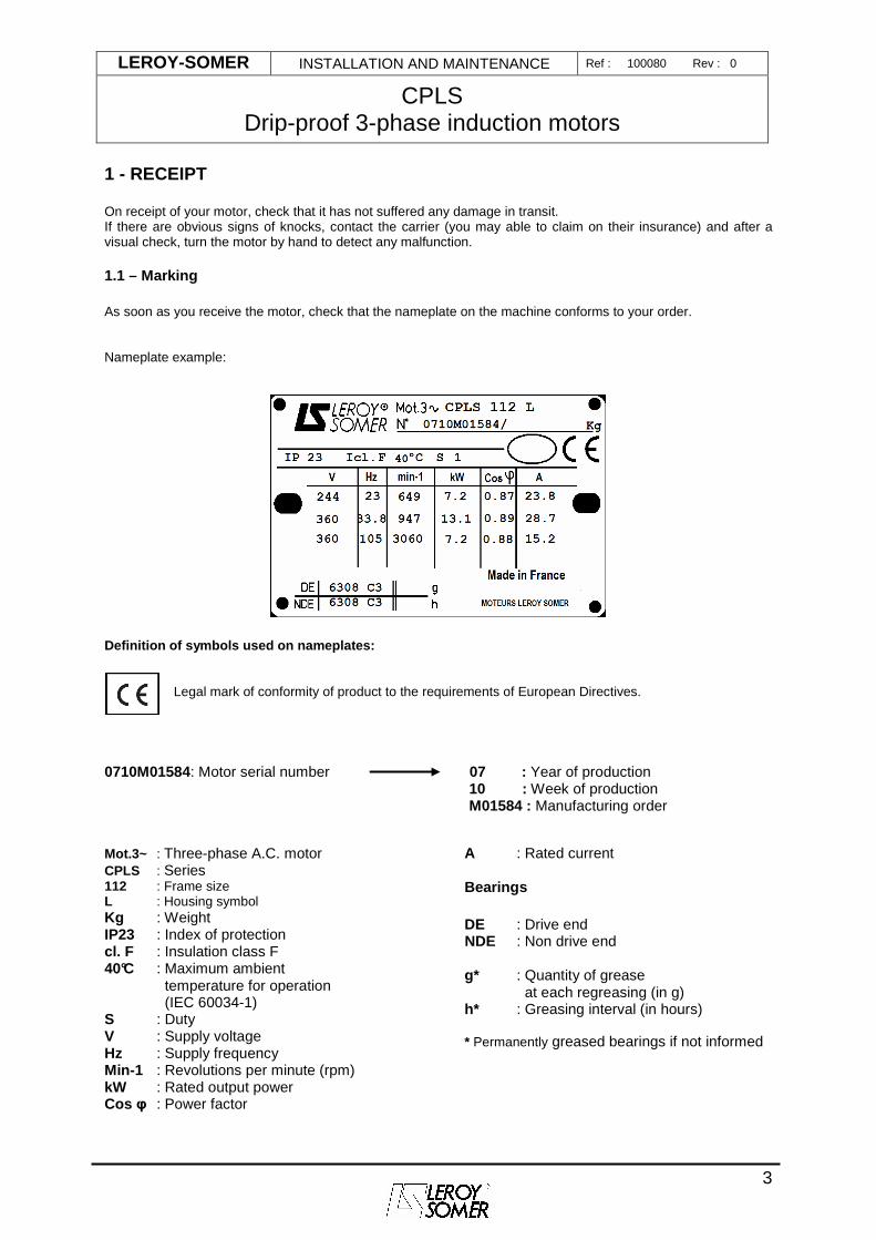
1.1 – Marking As soon as you receive the motor, check that the nameplate on the machine conforms to your order. Nameplate example:
Definition of symbols used on nameplates:
Legal mark of conformity of product to the requirements of European Directives.
0710M01584: Motor serial number 07 : Year of production
10 : Week of production M01584 : Manufacturing order
Mot.3~ : Three-phase A.C. motor CPLS : Series 112 : Frame size L : Housing symbol Kg : Weight IP23 : Index of protection cl. F : Insulation class F 40°C : Maximum ambient
temperature for operation (IEC 60034-1)
S : Duty V : Supply voltage Hz : Supply frequency Min-1 : Revolutions per minute (rpm) kW : Rated output power Cos φ : Power factor
A : Rated current Bearings DE : Drive end NDE : Non drive end
g* : Quantity of grease
at each regreasing (in g) h* : Greasing interval (in hours) * Permanently greased bearings if not informed
LEROY-SOMER INSTALLATION AND MAINTENANCE Ref : 100080 Rev : 0
CPLS Drip-proof 3-phase induction motors
4
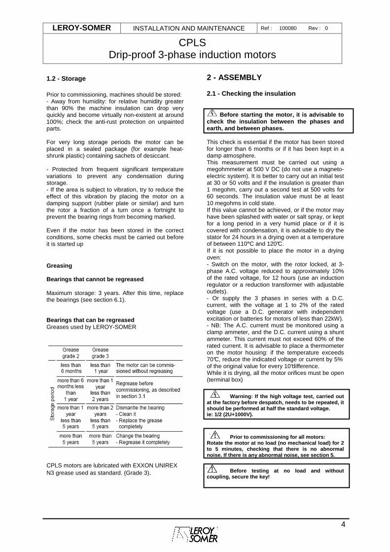
1.2 - Storage Prior to commissioning, machines should be stored: - Away from humidity: for relative humidity greater than 90% the machine insulation can drop very quickly and become virtually non-existent at around 100%; check the anti-rust protection on unpainted parts. For very long storage periods the motor can be placed in a sealed package (for example heat-shrunk plastic) containing sachets of desiccant. - Protected from frequent significant temperature variations to prevent any condensation during storage. - If the area is subject to vibration, try to reduce the effect of this vibration by placing the motor on a damping support (rubber plate or similar) and turn the rotor a fraction of a turn once a fortnight to prevent the bearing rings from becoming marked. Even if the motor has been stored in the correct conditions, some checks must be carried out before it is started up Greasing Bearings that cannot be regreased Maximum storage: 3 years. After this time, replace the bearings (see section 6.1). Bearings that can be regreased Greases used by LEROY-SOMER
CPLS motors are lubricated with EXXON UNIREX N3 grease used as standard. (Grade 3).
2 - ASSEMBLY
2.1 - Checking the insulation
Before starting the motor, it is advisable to
check the insulation between the phases and earth, and between phases. This check is essential if the motor has been stored for longer than 6 months or if it has been kept in a damp atmosphere. This measurement must be carried out using a megohmmeter at 500 V DC (do not use a magneto-electric system). It is better to carry out an initial test at 30 or 50 volts and if the insulation is greater than 1 megohm, carry out a second test at 500 volts for 60 seconds. The insulation value must be at least 10 megohms in cold state. If this value cannot be achieved, or if the motor may have been splashed with water or salt spray, or kept for a long period in a very humid place or if it is covered with condensation, it is advisable to dry the stator for 24 hours in a drying oven at a temperature of between 110°C and 120°C. If it is not possible to place the motor in a drying oven: - Switch on the motor, with the rotor locked, at 3-phase A.C. voltage reduced to approximately 10% of the rated voltage, for 12 hours (use an induction regulator or a reduction transformer with adjustable outlets). - Or supply the 3 phases in series with a D.C. current, with the voltage at 1 to 2% of the rated voltage (use a D.C. generator with independent excitation or batteries for motors of less than 22kW). - NB: The A.C. current must be monitored using a clamp ammeter, and the D.C. current using a shunt ammeter. This current must not exceed 60% of the rated current. It is advisable to place a thermometer on the motor housing: if the temperature exceeds 70°C, reduce the indicated voltage or current by 5% of the original value for every 10°difference. While it is drying, all the motor orifices must be open (terminal box)
Warning: If the high voltage test, carried out at the factory before despatch, needs to be repeate d, it should be performed at half the standard voltage. ie: 1/2 (2U+1000V).
Prior to commissioning for all motors: Rotate the motor at no load (no mechanical load) fo r 2 to 5 minutes, checking that there is no abnormal noise. If there is any abnormal noise, see section 5.
Before testing at no load and without coupling, secure the key!
LEROY-SOMER INSTALLATION AND MAINTENANCE Ref : 100080 Rev : 0
CPLS Drip-proof 3-phase induction motors
5
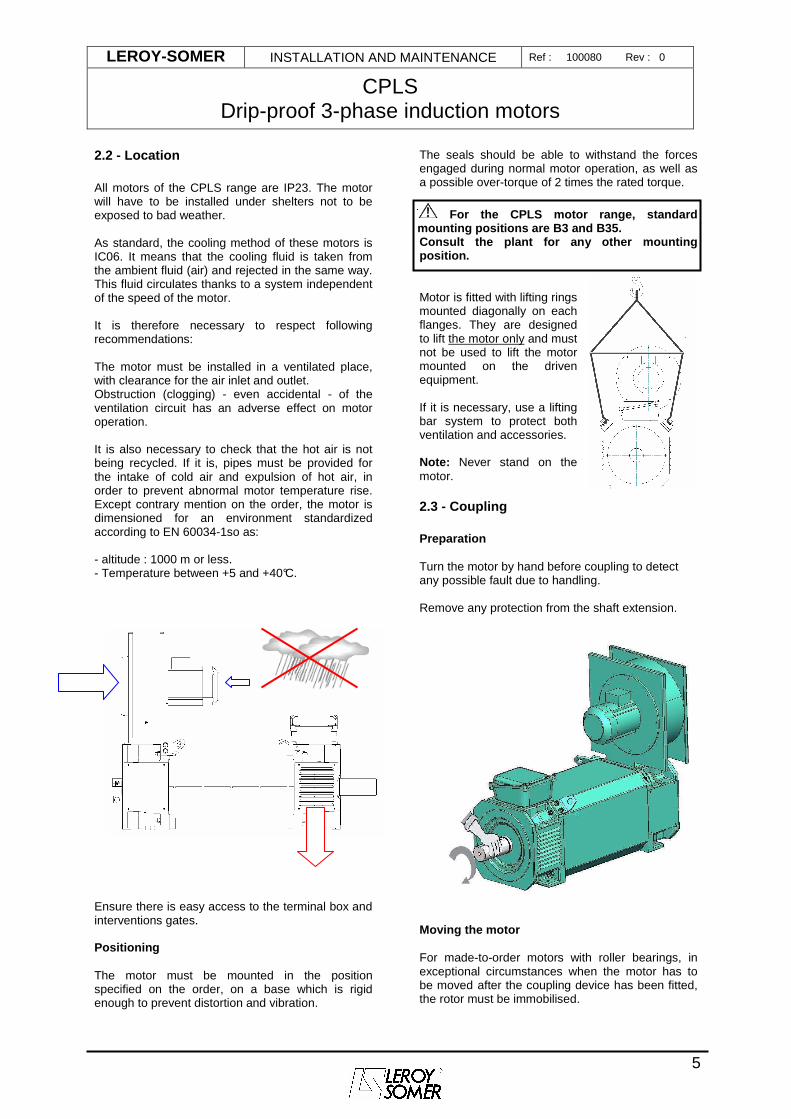
2.2 - Location All motors of the CPLS range are IP23. The motor will have to be installed under shelters not to be exposed to bad weather. As standard, the cooling method of these motors is IC06. It means that the cooling fluid is taken from the ambient fluid (air) and rejected in the same way. This fluid circulates thanks to a system independent of the speed of the motor. It is therefore necessary to respect following recommendations: The motor must be installed in a ventilated place, with clearance for the air inlet and outlet. Obstruction (clogging) - even accidental - of the ventilation circuit has an adverse effect on motor operation. It is also necessary to check that the hot air is not being recycled. If it is, pipes must be provided for the intake of cold air and expulsion of hot air, in order to prevent abnormal motor temperature rise. Except contrary mention on the order, the motor is dimensioned for an environment standardized according to EN 60034-1so as: - altitude : 1000 m or less. - Temperature between +5 and +40°C. Ensure there is easy access to the terminal box and interventions gates. Positioning The motor must be mounted in the position specified on the order, on a base which is rigid enough to prevent distortion and vibration.
The seals should be able to withstand the forces engaged during normal motor operation, as well as a possible over-torque of 2 times the rated torque.
For the CPLS motor range, standard mounting positions are B3 and B35. Consult the plant for any other mounting position. Motor is fitted with lifting rings mounted diagonally on each flanges. They are designed to lift the motor only and must not be used to lift the motor mounted on the driven equipment. If it is necessary, use a lifting bar system to protect both ventilation and accessories.
Note: Never stand on the motor.
2.3 - Coupling Preparation Turn the motor by hand before coupling to detect any possible fault due to handling. Remove any protection from the shaft extension.
Moving the motor For made-to-order motors with roller bearings, in exceptional circumstances when the motor has to be moved after the coupling device has been fitted, the rotor must be immobilised.
LEROY-SOMER INSTALLATION AND MAINTENANCE Ref : 100080 Rev : 0
CPLS Drip-proof 3-phase induction motors
6
Balancing Rotating machines are balanced in accordance with standard ISO 8821: - Half-key when the shaft extension is marked H: standard - No key when the shaft extension is marked N - Full key when the shaft extension is marked F Thus any coupling element (pulley, coupling sleeve, slipring,etc...) must be balanced accordingly. Motor with 2 shaft extensions: If the second shaft extension is not used, in order to comply with the balancing class, the key or half-key must be fixed firmly in the keyway so that it is not thrown out during rotation (H or F balancing) and must be protected against direct contact. Precautions All measures must be taken to ensure protection against the risks which arise when there are rotating parts (coupling sleeve, pulley, belt etc).
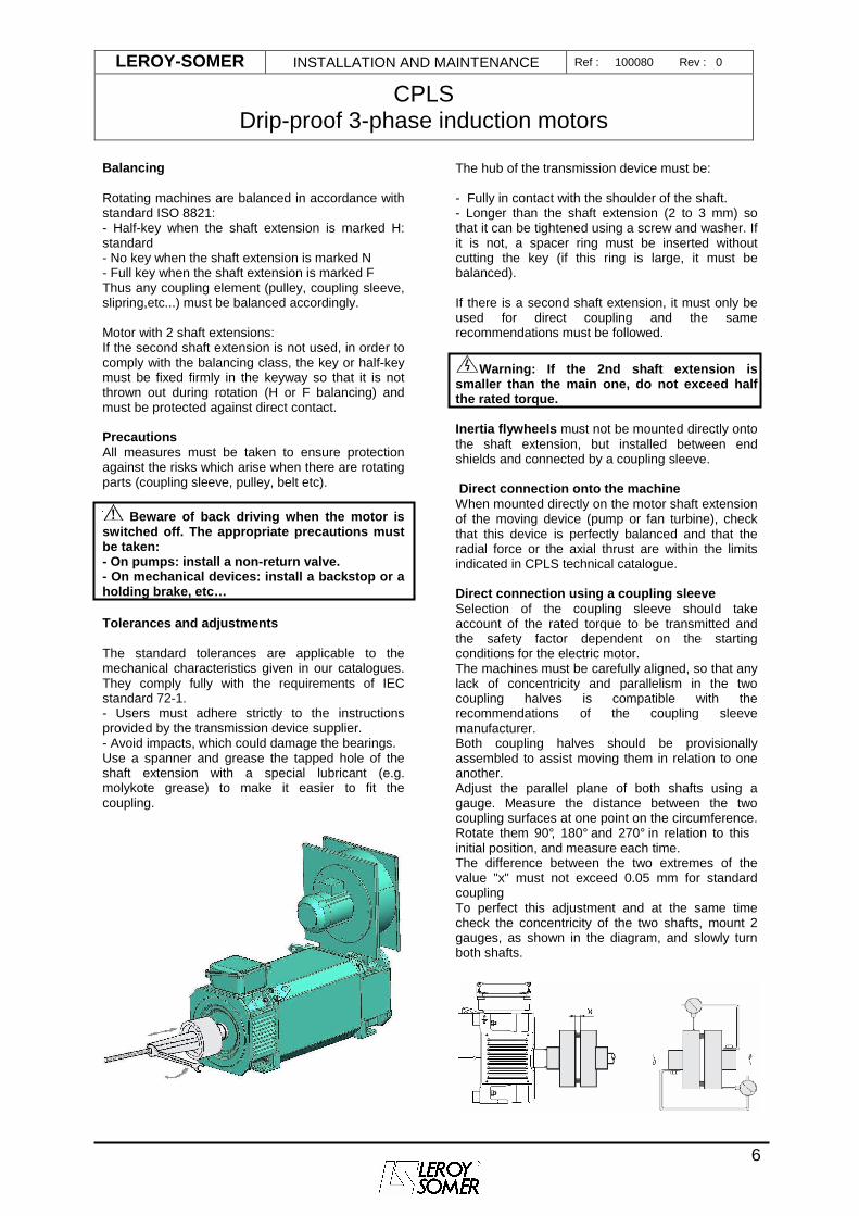
Beware of back driving when the motor is switched off. The appropriate precautions must be taken: - On pumps: install a non-return valve. - On mechanical devices: install a backstop or a holding brake, etc… Tolerances and adjustments The standard tolerances are applicable to the mechanical characteristics given in our catalogues. They comply fully with the requirements of IEC standard 72-1. - Users must adhere strictly to the instructions provided by the transmission device supplier. - Avoid impacts, which could damage the bearings. Use a spanner and grease the tapped hole of the shaft extension with a special lubricant (e.g. molykote grease) to make it easier to fit the coupling.
The hub of the transmission device must be: - Fully in contact with the shoulder of the shaft. - Longer than the shaft extension (2 to 3 mm) so that it can be tightened using a screw and washer. If it is not, a spacer ring must be inserted without cutting the key (if this ring is large, it must be balanced). If there is a second shaft extension, it must only be used for direct coupling and the same recommendations must be followed.
Warning: If the 2nd shaft extension is smaller than the main one, do not exceed half the rated torque. Inertia flywheels must not be mounted directly onto the shaft extension, but installed between end shields and connected by a coupling sleeve. Direct connection onto the machine When mounted directly on the motor shaft extension of the moving device (pump or fan turbine), check that this device is perfectly balanced and that the radial force or the axial thrust are within the limits indicated in CPLS technical catalogue. Direct connection using a coupling sleeve Selection of the coupling sleeve should take account of the rated torque to be transmitted and the safety factor dependent on the starting conditions for the electric motor. The machines must be carefully aligned, so that any lack of concentricity and parallelism in the two coupling halves is compatible with the recommendations of the coupling sleeve manufacturer. Both coupling halves should be provisionally assembled to assist moving them in relation to one another. Adjust the parallel plane of both shafts using a gauge. Measure the distance between the two coupling surfaces at one point on the circumference. Rotate them 90°, 180° and 270° in relation to this initial position, and measure each time. The difference between the two extremes of the value "x" must not exceed 0.05 mm for standard coupling To perfect this adjustment and at the same time check the concentricity of the two shafts, mount 2 gauges, as shown in the diagram, and slowly turn both shafts.
LEROY-SOMER INSTALLATION AND MAINTENANCE Ref : 100080 Rev : 0
CPLS Drip-proof 3-phase induction motors
7
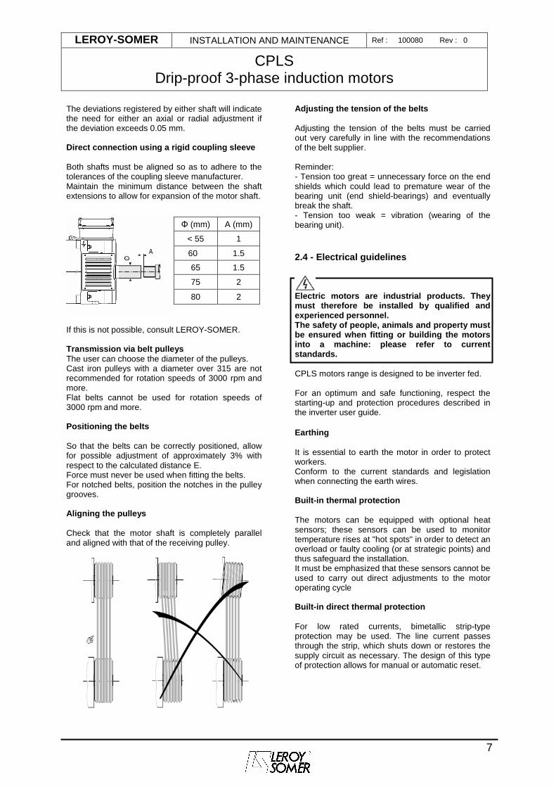
The deviations registered by either shaft will indicate the need for either an axial or radial adjustment if the deviation exceeds 0.05 mm. Direct connection using a rigid coupling sleeve Both shafts must be aligned so as to adhere to the tolerances of the coupling sleeve manufacturer. Maintain the minimum distance between the shaft extensions to allow for expansion of the motor shaft.
If this is not possible, consult LEROY-SOMER. Transmission via belt pulleys The user can choose the diameter of the pulleys. Cast iron pulleys with a diameter over 315 are not recommended for rotation speeds of 3000 rpm and more. Flat belts cannot be used for rotation speeds of 3000 rpm and more. Positioning the belts So that the belts can be correctly positioned, allow for possible adjustment of approximately 3% with respect to the calculated distance E. Force must never be used when fitting the belts. For notched belts, position the notches in the pulley grooves. Aligning the pulleys Check that the motor shaft is completely parallel and aligned with that of the receiving pulley.
Adjusting the tension of the belts Adjusting the tension of the belts must be carried out very carefully in line with the recommendations of the belt supplier. Reminder: - Tension too great = unnecessary force on the end shields which could lead to premature wear of the bearing unit (end shield-bearings) and eventually break the shaft. - Tension too weak = vibration (wearing of the bearing unit).
2.4 - Electrical guidelines
Electric motors are industrial products. They must therefore be installed by qualified and experienced personnel. The safety of people, animals and property must be ensured when fitting or building the motors into a machine: please refer to current standards. CPLS motors range is designed to be inverter fed. For an optimum and safe functioning, respect the starting-up and protection procedures described in the inverter user guide. Earthing It is essential to earth the motor in order to protect workers. Conform to the current standards and legislation when connecting the earth wires. Built-in thermal protection The motors can be equipped with optional heat sensors; these sensors can be used to monitor temperature rises at "hot spots" in order to detect an overload or faulty cooling (or at strategic points) and thus safeguard the installation. It must be emphasized that these sensors cannot be used to carry out direct adjustments to the motor operating cycle Built-in direct thermal protection For low rated currents, bimetallic strip-type protection may be used. The line current passes through the strip, which shuts down or restores the supply circuit as necessary. The design of this type of protection allows for manual or automatic reset.
Φ (mm) A (mm)
< 55 1
60 1.5
65 1.5
75 2
80 2
LEROY-SOMER INSTALLATION AND MAINTENANCE Ref : 100080 Rev : 0
CPLS Drip-proof 3-phase induction motors
8
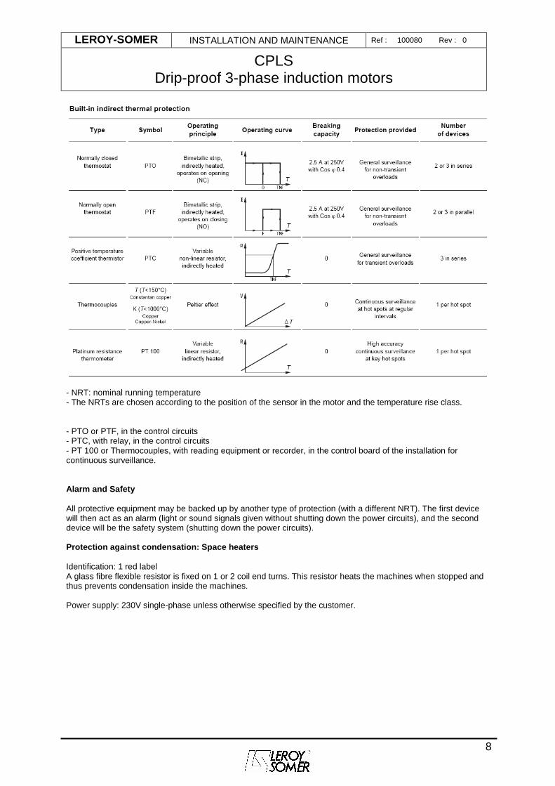
- NRT: nominal running temperature - The NRTs are chosen according to the position of the sensor in the motor and the temperature rise class. - PTO or PTF, in the control circuits - PTC, with relay, in the control circuits - PT 100 or Thermocouples, with reading equipment or recorder, in the control board of the installation for continuous surveillance. Alarm and Safety All protective equipment may be backed up by another type of protection (with a different NRT). The first device will then act as an alarm (light or sound signals given without shutting down the power circuits), and the second device will be the safety system (shutting down the power circuits). Protection against condensation: Space heaters Identification: 1 red label A glass fibre flexible resistor is fixed on 1 or 2 coil end turns. This resistor heats the machines when stopped and thus prevents condensation inside the machines. Power supply: 230V single-phase unless otherwise specified by the customer.
LEROY-SOMER INSTALLATION AND MAINTENANCE Ref : 100080 Rev : 0
CPLS Drip-proof 3-phase induction motors
9
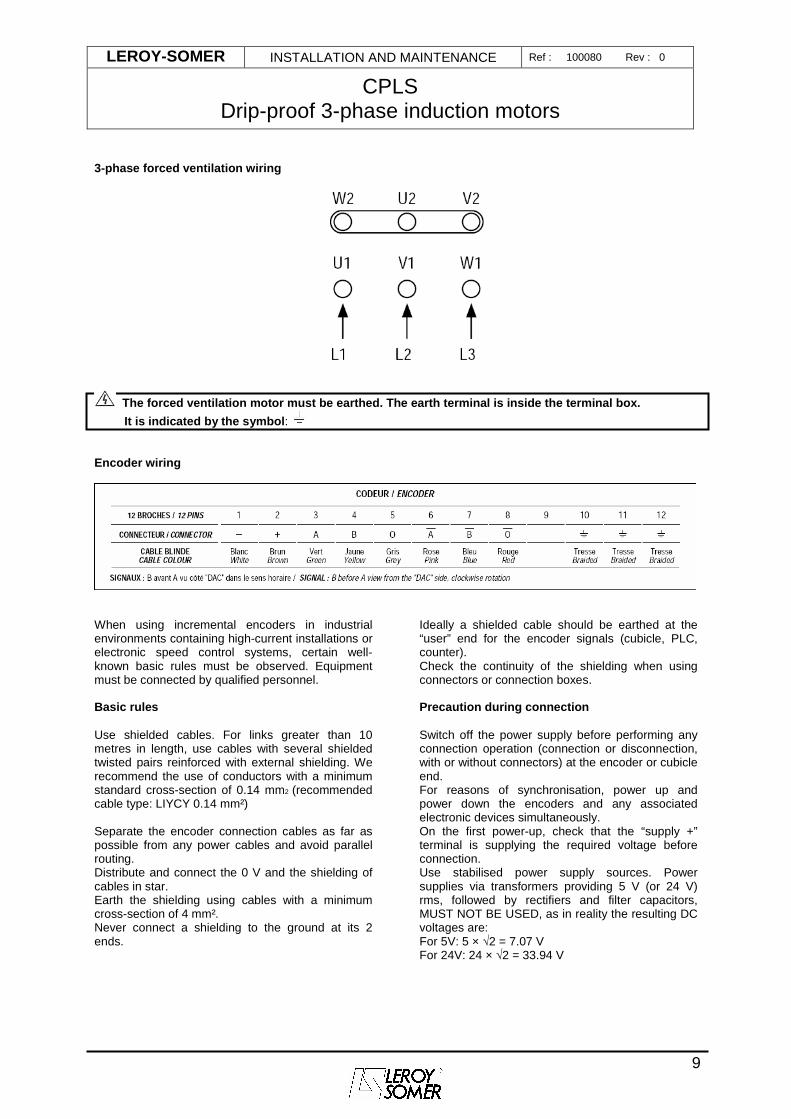
3-phase forced ventilation wiring
The forced ventilation motor must be earthed. The earth terminal is inside the terminal box.
It is indicated by the symbol : Encoder wiring
When using incremental encoders in industrial environments containing high-current installations or electronic speed control systems, certain well-known basic rules must be observed. Equipment must be connected by qualified personnel. Basic rules Use shielded cables. For links greater than 10 metres in length, use cables with several shielded twisted pairs reinforced with external shielding. We recommend the use of conductors with a minimum standard cross-section of 0.14 mm2 (recommended cable type: LIYCY 0.14 mm²) Separate the encoder connection cables as far as possible from any power cables and avoid parallel routing. Distribute and connect the 0 V and the shielding of cables in star. Earth the shielding using cables with a minimum cross-section of 4 mm². Never connect a shielding to the ground at its 2 ends.
Ideally a shielded cable should be earthed at the “user” end for the encoder signals (cubicle, PLC, counter). Check the continuity of the shielding when using connectors or connection boxes. Precaution during connection Switch off the power supply before performing any connection operation (connection or disconnection, with or without connectors) at the encoder or cubicle end. For reasons of synchronisation, power up and power down the encoders and any associated electronic devices simultaneously. On the first power-up, check that the “supply +” terminal is supplying the required voltage before connection. Use stabilised power supply sources. Power supplies via transformers providing 5 V (or 24 V) rms, followed by rectifiers and filter capacitors, MUST NOT BE USED, as in reality the resulting DC voltages are: For 5V: 5 × √2 = 7.07 V For 24V: 24 × √2 = 33.94 V
LEROY-SOMER INSTALLATION AND MAINTENANCE Ref : 100080 Rev : 0
CPLS Drip-proof 3-phase induction motors
10
2.5 - Main connections.
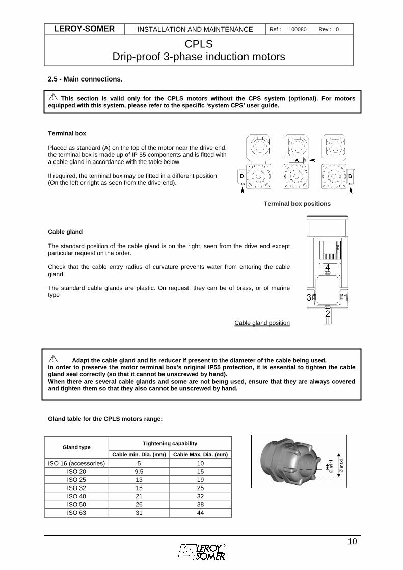
This section is valid only for the CPLS motors withou t the CPS system (optional). For motors equipped with this system, please refer to the spec ific ‘system CPS’ user guide. Terminal box Placed as standard (A) on the top of the motor near the drive end, the terminal box is made up of IP 55 components and is fitted with a cable gland in accordance with the table below. If required, the terminal box may be fitted in a different position (On the left or right as seen from the drive end). Terminal box positions
Cable gland The standard position of the cable gland is on the right, seen from the drive end except particular request on the order. Check that the cable entry radius of curvature prevents water from entering the cable gland. The standard cable glands are plastic. On request, they can be of brass, or of marine type
Cable gland position
Adapt the cable gland and its reducer if present to the diameter of the cable being used. In order to preserve the motor terminal box's origi nal IP55 protection, it is essential to tighten the cable gland seal correctly (so that it cannot be unscrewe d by hand). When there are several cable glands and some are no t being used, ensure that they are always covered and tighten them so that they also cannot be unscre wed by hand. Gland table for the CPLS motors range:
Tightening capability Gland type
Cable min. Dia. (mm) Cable Max. Dia. (mm)
ISO 16 (accessories) 5 10 ISO 20 9.5 15 ISO 25 13 19 ISO 32 15 25 ISO 40 21 32 ISO 50 26 38 ISO 63 31 44
LEROY-SOMER INSTALLATION AND MAINTENANCE Ref : 100080 Rev : 0
CPLS Drip-proof 3-phase induction motors
11
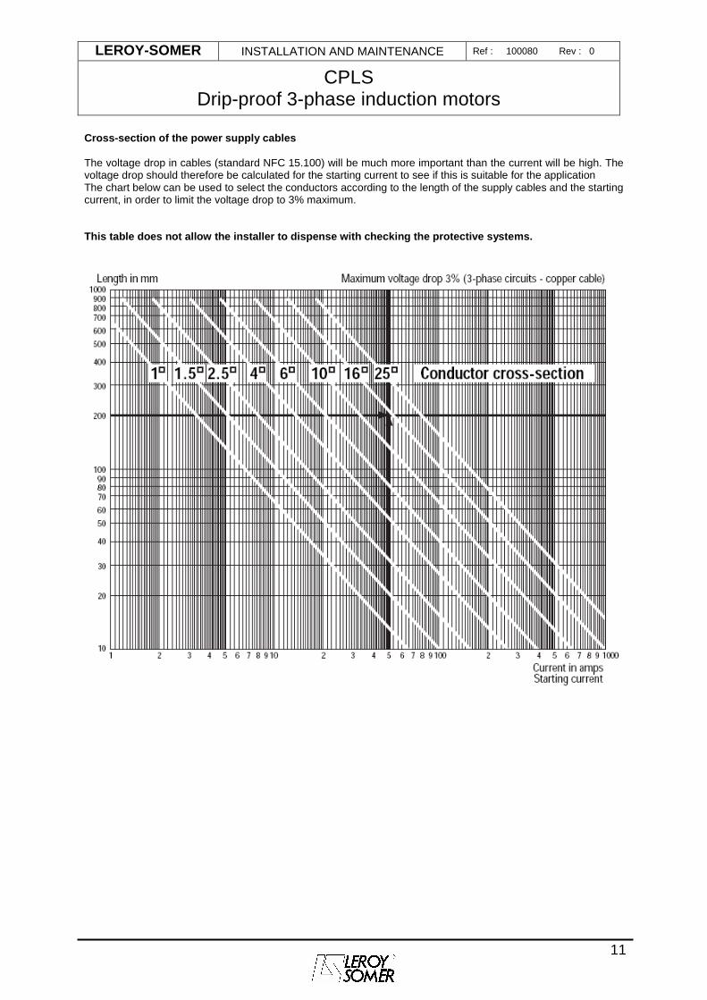
Cross-section of the power supply cables The voltage drop in cables (standard NFC 15.100) will be much more important than the current will be high. The voltage drop should therefore be calculated for the starting current to see if this is suitable for the application The chart below can be used to select the conductors according to the length of the supply cables and the starting current, in order to limit the voltage drop to 3% maximum. This table does not allow the installer to dispense with checking the protective systems.
LEROY-SOMER INSTALLATION AND MAINTENANCE Ref : 100080 Rev : 0
CPLS Drip-proof 3-phase induction motors
12
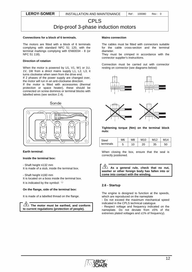
Connections for a block of 6 terminals. The motors are fitted with a block of 6 terminals complying with standard NFC 51 120, with the terminal markings complying with EN60034 - 8 (or NFC 51 118). Direction of rotation When the motor is powered by U1, V1, W1 or 1U, 1V, 1W from a direct mains supply L1, L2, L3, it turns clockwise when seen from the drive end. If 2 phases of the power supply are changed over, the motor will run in an anti-clockwise direction. If the motor is fitted with accessories (thermal protection or space heater), these should be connected on screw dominos or terminal blocks with labelled wires (see section 2.4).
Earth terminal: Inside the terminal box: - Shaft height ≤132 mm It is made of a stub, inside the terminal box. - Shaft height ≥160 mm It is located on a boss inside the terminal box.
It is indicated by the symbol: On the flange, side of the terminal box: It is made of a labelled thread on the flange.
The motor must be earthed, and conform to current regulations (protection of people).
Mains connection The cables must be fitted with connectors suitable for the cable cross-section and the terminal diameter. They must be crimped in accordance with the connector supplier’s instructions. Connection must be carried out with connector resting on connector (see diagrams below):
Tightening torque (Nm) on the terminal block nuts:
When closing the box, ensure that the seal is correctly positioned.
As a general rule, check that no nut, washer or other foreign body has fallen into or come into contact with the winding.
2.6 - Startup The engine is designed to function at the speeds, which are reproduced on the nameplate - Do not exceed the maximum mechanical speed indicated in the CPLS technical catalogue. - Respect voltage and frequency indicated on the nameplate. Do not deviate from ±5% of the extremes plated voltages and ±1% of frequency).
M6 M8 M10 M12 M14 Steel terminals 5 10 20 35 50
LEROY-SOMER INSTALLATION AND MAINTENANCE Ref : 100080 Rev : 0
CPLS Drip-proof 3-phase induction motors
13
3 - ROUTINE MAINTENANCE Checks after start-up After approximately 50 hours operation, check that the screws fixing the motor and the coupling device are still tight. In the case of chain or belt transmission, check that the voltage is correctly adjusted. Ventilation To ensure correct motor operation, take steps to prevent dust and foreign bodies from clogging forced ventilation and DE shield louvers. For forced ventilations equipped with standard or vinyl filters (optional in both cases), it is necessary to clean the filter periodically (having disassembled it), with compressed air, according to the pollution of ambient air. If the clogging of the filter is too important, replace it. Cleaning Dry cleaning (vacuuming or compressed air) is recommended. Cleaning must always be carried out at low pressure to avoid dust and particles getting under the seals. Precaution: check that the motor is totally sealed (terminal box, etc) before carrying out any cleaning operation.
Wet cleaning (water hose or high pressure cleaner) is to be avoided.
3.1 - Checking the bearings
As soon as you detect any of the following on the motor: - A noise or abnormal vibration - Abnormal heating of the bearing when it is correctly greased, the state of the bearings must be checked. Damaged bearings must be replaced as soon as possible to prevent worse damage to the motor and the equipment being driven. When one bearing needs to be replaced, the other bearing must also be replaced. The seals should be changed routinely when the bearings are changed. The drive end shield (D.E.) bearing must be freely mounted to allow for expansion of the rotor shaft.
3.2 - Greasing As standard, all motors of the CPLS range are equipped with sealed bearings (Shields without grease nipple). For specific applications, such as high speeds or heavy loads, motors can be equipped with open ball bearings or cylindrical roller bearings. In this case
the shields are fitted with grease nipples Tecalemit-Hydraulic M8 x 125. As standard, the bearings are lubricated with EXXON UNIREX N3 grease, and we recommend that it is used for subsequent lubrication. Avoid mixing greases. -The interval of time between two successive regreasings can depend of additional parameters like ambient temperature or type of grease (if not EXXON UNIREX N3)
The lubrication intervals, quantity and quality of grease, are indicated on the motor nameplate.
Even in the event of prolonged storage or downtime, the interval between 2 greasing operations should never exceed 2 years. Regreasing Always begin by cleaning the waste grease channel. When using the grease shown on the nameplate, remove the covers and clean the grease nipple heads. Efficient greasing only really occurs with the motor running, which ensures that the new grease is well distributed in the bearing. If greasing cannot be carried out with the motor running (mainly for safety reasons): - Stop the motor - Inject only half the amount of grease shown on the nameplate - Turn the motor for a few minutes - Add more grease until the quantity indicated is reached. Note: When using a different type of grease to that indicated but of similar quality, the motor must be dismantled and the bearings and accessories cleaned (carefully clean the grease inlet and outlet channels) to remove the old grease before regreasing. Then proceed as indicated in paragraph 6 (corrective maintenance).
Too much grease causes the bearing to overheat (statistics show that more bearings are damaged through too much grease than too little grease).
The new grease must be recently manufactured and must not contain any impurities (dust, water, etc).
LEROY-SOMER INSTALLATION AND MAINTENANCE Ref : 100080 Rev : 0
CPLS Drip-proof 3-phase induction motors
14
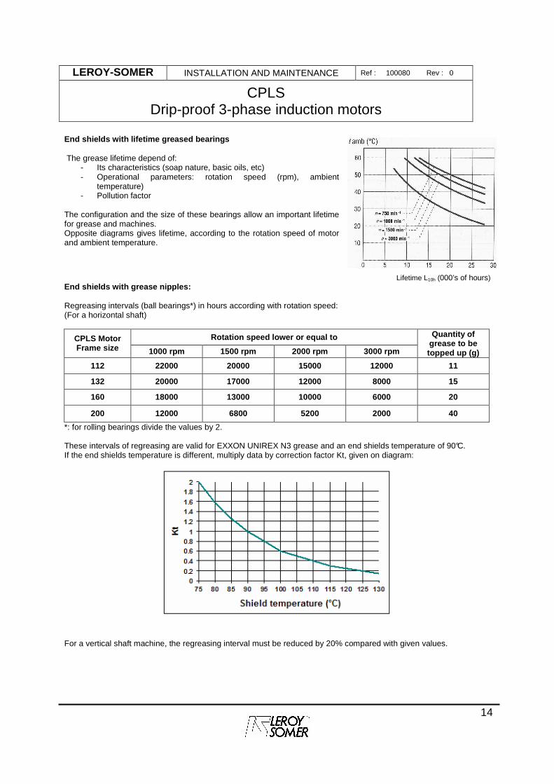
End shields with lifetime greased bearings The grease lifetime depend of:
- Its characteristics (soap nature, basic oils, etc) - Operational parameters: rotation speed (rpm), ambient
temperature) - Pollution factor
The configuration and the size of these bearings allow an important lifetime for grease and machines. Opposite diagrams gives lifetime, according to the rotation speed of motor and ambient temperature.
Lifetime L10h (000’s of hours)
End shields with grease nipples: Regreasing intervals (ball bearings*) in hours according with rotation speed: (For a horizontal shaft)
Rotation speed lower or equal to CPLS Motor Frame size 1000 rpm 1500 rpm 2000 rpm 3000 rpm
Quantity of grease to be topped up (g)
112 22000 20000 15000 12000 11
132 20000 17000 12000 8000 15
160 18000 13000 10000 6000 20
200 12000 6800 5200 2000 40
*: for rolling bearings divide the values by 2. These intervals of regreasing are valid for EXXON UNIREX N3 grease and an end shields temperature of 90°C. If the end shields temperature is different, multiply data by correction factor Kt, given on diagram:
For a vertical shaft machine, the regreasing interval must be reduced by 20% compared with given values.
LEROY-SOMER INSTALLATION AND MAINTENANCE Ref : 100080 Rev : 0
CPLS Drip-proof 3-phase induction motors
15
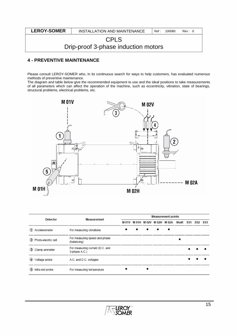
4 - PREVENTIVE MAINTENANCE Please consult LEROY-SOMER who, in its continuous search for ways to help customers, has evaluated numerous methods of preventive maintenance. The diagram and table below give the recommended equipment to use and the ideal positions to take measurements of all parameters which can affect the operation of the machine, such as eccentricity, vibration, state of bearings, structural problems, electrical problems, etc.
LEROY-SOMER INSTALLATION AND MAINTENANCE Ref : 100080 Rev : 0
CPLS Drip-proof 3-phase induction motors
16
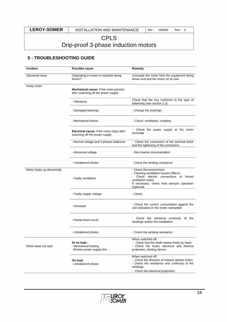
5 - TROUBLESHOOTING GUIDE Incident Possible cause
Remedy
Abnormal noise
Originating in motor or machine being driven?
Uncouple the motor from the equipment being driven and test the motor on its own
Noisy motor
Mechanical cause: if the noise persists after switching off the power supply
- Vibrations Check that the key conforms to the type of
balancing (see section 2.3)
- Damaged bearings
- Change the bearings
- Mechanical friction
- Check: ventilation, coupling
Electrical cause: if the noise stops after switching off the power supply
- Check the power supply at the motor terminals
- Normal voltage and 3 phases balanced
- Check the connection of the terminal block and the tightening of the connectors
- Abnormal voltage
- See inverter documentation
- Unbalanced phase
- Check the winding resistance
Motor heats up abnormally
- Faulty ventilation
- Check the environment - Cleaning ventilation louvers (filters) - Check electric connections of forced ventilation motor. If necessary, check heat sensors operation (optional)
- Faulty supply voltage
- Check
- Overload
- Check the current consumption against the one indicated on the motor nameplate
- Partial short-circuit
- Check the electrical continuity of the windings and/or the installation
- Unbalanced phase
- Check the winding resistance
Motor does not start
At no load : - Mechanical locking - Broken power supply line
When switched off: - Check that the shaft rotates freely by hand - Check the fuses, electrical and thermal protection, starting device.
On load - Unbalanced phase
When switched off: - Check the direction of rotation (phase order) - Check the resistance and continuity of the windings - Check the electrical protection.
LEROY-SOMER INSTALLATION AND MAINTENANCE Ref : 100080 Rev : 0
CPLS Drip-proof 3-phase induction motors
17
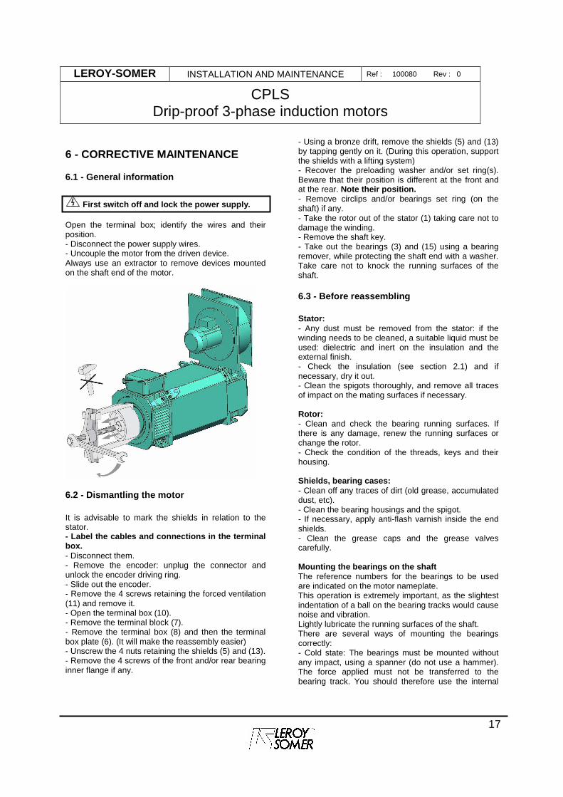
6 - CORRECTIVE MAINTENANCE
6.1 - General information
First switch off and lock the power supply. Open the terminal box; identify the wires and their position. - Disconnect the power supply wires. - Uncouple the motor from the driven device. Always use an extractor to remove devices mounted on the shaft end of the motor.
6.2 - Dismantling the motor It is advisable to mark the shields in relation to the stator. - Label the cables and connections in the terminal box. - Disconnect them. - Remove the encoder: unplug the connector and unlock the encoder driving ring. - Slide out the encoder. - Remove the 4 screws retaining the forced ventilation (11) and remove it. - Open the terminal box (10). - Remove the terminal block (7). - Remove the terminal box (8) and then the terminal box plate (6). (It will make the reassembly easier) - Unscrew the 4 nuts retaining the shields (5) and (13). - Remove the 4 screws of the front and/or rear bearing inner flange if any.
- Using a bronze drift, remove the shields (5) and (13) by tapping gently on it. (During this operation, support the shields with a lifting system) - Recover the preloading washer and/or set ring(s). Beware that their position is different at the front and at the rear. Note their position. - Remove circlips and/or bearings set ring (on the shaft) if any. - Take the rotor out of the stator (1) taking care not to damage the winding. - Remove the shaft key. - Take out the bearings (3) and (15) using a bearing remover, while protecting the shaft end with a washer. Take care not to knock the running surfaces of the shaft.
6.3 - Before reassembling Stator: - Any dust must be removed from the stator: if the winding needs to be cleaned, a suitable liquid must be used: dielectric and inert on the insulation and the external finish. - Check the insulation (see section 2.1) and if necessary, dry it out. - Clean the spigots thoroughly, and remove all traces of impact on the mating surfaces if necessary. Rotor: - Clean and check the bearing running surfaces. If there is any damage, renew the running surfaces or change the rotor. - Check the condition of the threads, keys and their housing. Shields, bearing cases: - Clean off any traces of dirt (old grease, accumulated dust, etc). - Clean the bearing housings and the spigot. - If necessary, apply anti-flash varnish inside the end shields. - Clean the grease caps and the grease valves carefully. Mounting the bearings on the shaft The reference numbers for the bearings to be used are indicated on the motor nameplate. This operation is extremely important, as the slightest indentation of a ball on the bearing tracks would cause noise and vibration. Lightly lubricate the running surfaces of the shaft. There are several ways of mounting the bearings correctly: - Cold state: The bearings must be mounted without any impact, using a spanner (do not use a hammer). The force applied must not be transferred to the bearing track. You should therefore use the internal
LEROY-SOMER INSTALLATION AND MAINTENANCE Ref : 100080 Rev : 0
CPLS Drip-proof 3-phase induction motors
18
cage for support (taking care not to press on the seal shield for dust and damp protected bearings). - Hot state: Heat the bearing to between 80 and 100°C in a dryer, an oven or on a heating plate. (A blowtorch must never be used for heating, just as an oil bath must not be used for heating permanently greased bearings).
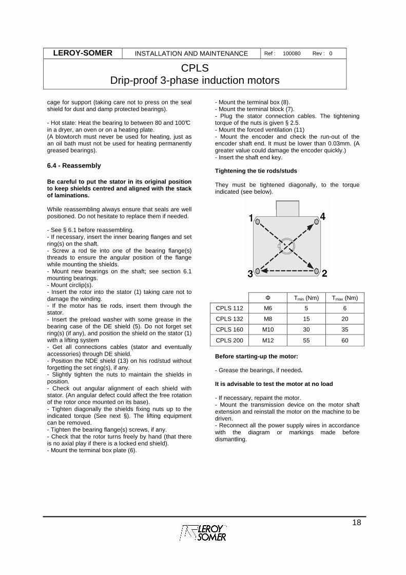
6.4 - Reassembly Be careful to put the stator in its original positi on to keep shields centred and aligned with the stack of laminations. While reassembling always ensure that seals are well positioned. Do not hesitate to replace them if needed. - See § 6.1 before reassembling. - If necessary, insert the inner bearing flanges and set ring(s) on the shaft. - Screw a rod tie into one of the bearing flange(s) threads to ensure the angular position of the flange while mounting the shields. - Mount new bearings on the shaft; see section 6.1 mounting bearings. - Mount circlip(s). - Insert the rotor into the stator (1) taking care not to damage the winding. - If the motor has tie rods, insert them through the stator. - Insert the preload washer with some grease in the bearing case of the DE shield (5). Do not forget set ring(s) (if any), and position the shield on the stator (1) with a lifting system - Get all connections cables (stator and eventually accessories) through DE shield. - Position the NDE shield (13) on his rod/stud without forgetting the set ring(s), if any. - Slightly tighten the nuts to maintain the shields in position. - Check out angular alignment of each shield with stator. (An angular defect could affect the free rotation of the rotor once mounted on its base). - Tighten diagonally the shields fixing nuts up to the indicated torque (See next §). The lifting equipment can be removed. - Tighten the bearing flange(s) screws, if any. - Check that the rotor turns freely by hand (that there is no axial play if there is a locked end shield). - Mount the terminal box plate (6).
- Mount the terminal box (8). - Mount the terminal block (7). - Plug the stator connection cables. The tightening torque of the nuts is given § 2.5. - Mount the forced ventilation (11) - Mount the encoder and check the run-out of the encoder shaft end. It must be lower than 0.03mm. (A greater value could damage the encoder quickly.) - Insert the shaft end key. Tightening the tie rods/studs They must be tightened diagonally, to the torque indicated (see below).
Φ Tmin (Nm) Tmax (Nm)
CPLS 112 M6 5 6
CPLS 132 M8 15 20
CPLS 160 M10 30 35
CPLS 200 M12 55 60
Before starting-up the motor: - Grease the bearings, if needed. It is advisable to test the motor at no load - If necessary, repaint the motor. - Mount the transmission device on the motor shaft extension and reinstall the motor on the machine to be driven. - Reconnect all the power supply wires in accordance with the diagram or markings made before dismantling.
LEROY-SOMER INSTALLATION AND MAINTENANCE Ref : 100080 Rev : 0
CPLS Drip-proof 3-phase induction motors
19
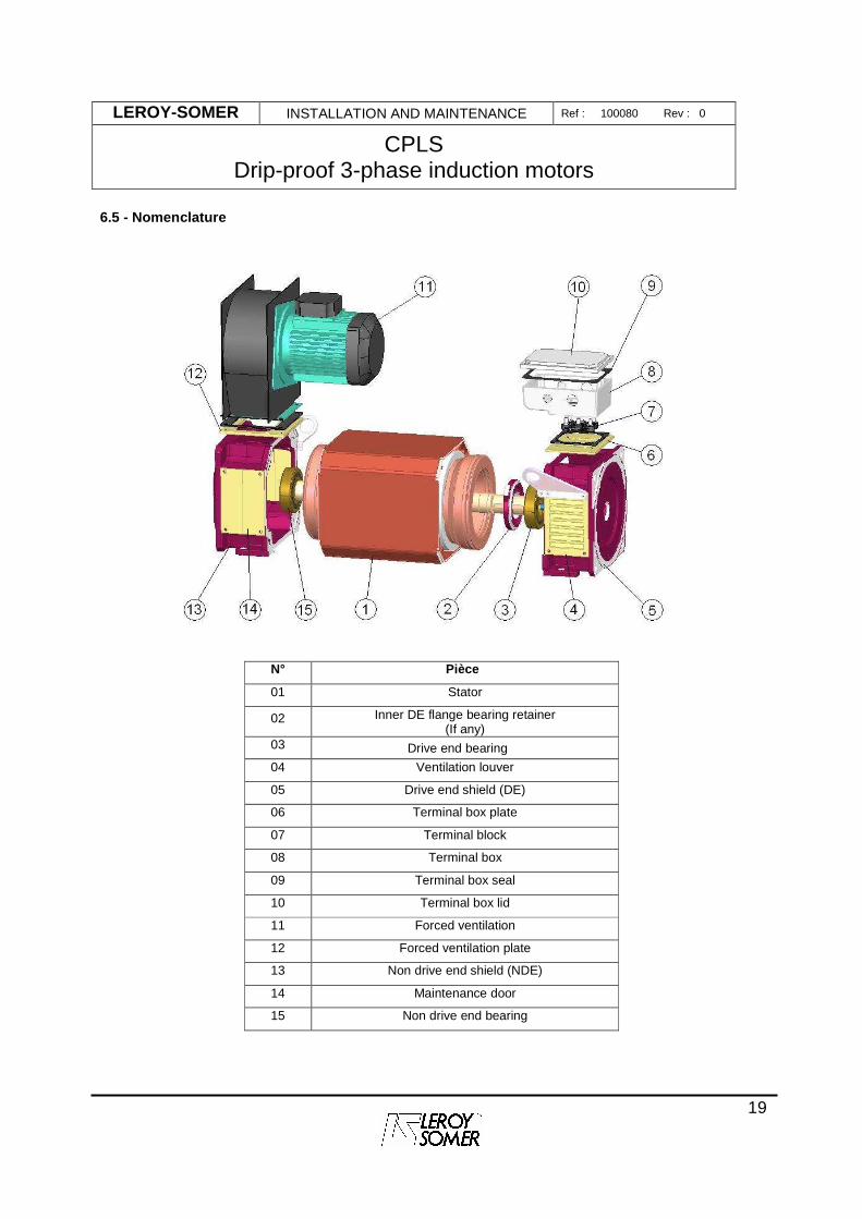
6.5 - Nomenclature
N° Pièce
01 Stator
02 Inner DE flange bearing retainer (If any)
03 Drive end bearing
04 Ventilation louver
05 Drive end shield (DE)
06 Terminal box plate
07 Terminal block
08 Terminal box
09 Terminal box seal
10 Terminal box lid
11 Forced ventilation
12 Forced ventilation plate
13 Non drive end shield (NDE)
14 Maintenance door
15 Non drive end bearing

LEROY-SOMER INSTALLATION AND MAINTENANCE Ref : 100080 Rev : 0
CPLS Drip-proof 3-phase induction motors
20
7 - SPARE PARTS When ordering spare parts, you must indicate the complete motor type, its serial number and the information given on the nameplate (see section 1). Part numbers can be found on the exploded views and their descriptions in the parts list (section § 6.4) To ensure that our motors operate correctly and safely, we recommend the use of original manufacturer spare parts. In the event of failure to comply with this advice, the manufacturer cannot be held responsible for any damage.

8 - INDEX Balancing........................................................................................................................................................................ 6 Belts ............................................................................................................................................................................... 7 Built-in thermal protection............................................................................................................................................... 7 Cable gland .................................................................................................................................................................. 10 Connections.................................................................................................................................................................. 12 Coupling ..................................................................................................................................................................... 5, 6 Coupling sleeve.............................................................................................................................................................. 6 Direction of rotation ...................................................................................................................................................... 12 Dismantling the motor................................................................................................................................................... 17 Encoder .......................................................................................................................................................................... 9 Forced ventilation ........................................................................................................................................................... 9 Greasing....................................................................................................................................................................... 13 Inertia flywheels.............................................................................................................................................................. 6 Insulation ........................................................................................................................................................................ 4 Location.......................................................................................................................................................................... 5 Main connections.......................................................................................................................................................... 10 Mains connection.......................................................................................................................................................... 12 Manutention.................................................................................................................................................................... 5 Positioning...................................................................................................................................................................... 5 Pulleys............................................................................................................................................................................ 7 Reassembly.................................................................................................................................................................. 18 Receipt ........................................................................................................................................................................... 3 Space heaters ................................................................................................................................................................ 8 Storage........................................................................................................................................................................... 4 Terminal blocks ............................................................................................................................................................ 12 Terminal box................................................................................................................................................................. 10 Tie rods
Tightening................................................................................................................................................................ 18 Troubleshooting............................................................................................................................................................ 16 Ventilation................................................................................................................................................................. 5, 13

Notes :