cps operations guide · vsrvcc 158 w 159 wispr 159 x 159 xml 159 interfacesinthegprsnetwork 159 ga...
TRANSCRIPT
Cisco Policy Suite Operations Guide Release 8.1.0First Published: January 22, 2016
Last Modified: January 22, 2016
Americas HeadquartersCisco Systems, Inc.170 West Tasman DriveSan Jose, CA 95134-1706USAhttp://www.cisco.comTel: 408 526-4000 800 553-NETS (6387)Fax: 408 527-0883

THE SPECIFICATIONS AND INFORMATION REGARDING THE PRODUCTS IN THIS MANUAL ARE SUBJECT TO CHANGE WITHOUT NOTICE. ALL STATEMENTS,INFORMATION, AND RECOMMENDATIONS IN THIS MANUAL ARE BELIEVED TO BE ACCURATE BUT ARE PRESENTED WITHOUT WARRANTY OF ANY KIND,EXPRESS OR IMPLIED. USERS MUST TAKE FULL RESPONSIBILITY FOR THEIR APPLICATION OF ANY PRODUCTS.
THE SOFTWARE LICENSE AND LIMITEDWARRANTY FOR THE ACCOMPANYING PRODUCT ARE SET FORTH IN THE INFORMATION PACKET THAT SHIPPED WITHTHE PRODUCT AND ARE INCORPORATED HEREIN BY THIS REFERENCE. IF YOU ARE UNABLE TO LOCATE THE SOFTWARE LICENSE OR LIMITED WARRANTY,CONTACT YOUR CISCO REPRESENTATIVE FOR A COPY.
The Cisco implementation of TCP header compression is an adaptation of a program developed by the University of California, Berkeley (UCB) as part of UCB's public domain versionof the UNIX operating system. All rights reserved. Copyright © 1981, Regents of the University of California.
NOTWITHSTANDINGANYOTHERWARRANTYHEREIN, ALL DOCUMENT FILES AND SOFTWARE OF THESE SUPPLIERS ARE PROVIDED “AS IS"WITH ALL FAULTS.CISCO AND THE ABOVE-NAMED SUPPLIERS DISCLAIM ALL WARRANTIES, EXPRESSED OR IMPLIED, INCLUDING, WITHOUT LIMITATION, THOSE OFMERCHANTABILITY, FITNESS FORA PARTICULAR PURPOSEANDNONINFRINGEMENTORARISING FROMACOURSEOFDEALING, USAGE, OR TRADE PRACTICE.
IN NO EVENT SHALL CISCO OR ITS SUPPLIERS BE LIABLE FOR ANY INDIRECT, SPECIAL, CONSEQUENTIAL, OR INCIDENTAL DAMAGES, INCLUDING, WITHOUTLIMITATION, LOST PROFITS OR LOSS OR DAMAGE TO DATA ARISING OUT OF THE USE OR INABILITY TO USE THIS MANUAL, EVEN IF CISCO OR ITS SUPPLIERSHAVE BEEN ADVISED OF THE POSSIBILITY OF SUCH DAMAGES.
Any Internet Protocol (IP) addresses and phone numbers used in this document are not intended to be actual addresses and phone numbers. Any examples, command display output, networktopology diagrams, and other figures included in the document are shown for illustrative purposes only. Any use of actual IP addresses or phone numbers in illustrative content is unintentionaland coincidental.
Cisco and the Cisco logo are trademarks or registered trademarks of Cisco and/or its affiliates in the U.S. and other countries. To view a list of Cisco trademarks, go to this URL: http://www.cisco.com/go/trademarks. Third-party trademarks mentioned are the property of their respective owners. The use of the word partner does not imply a partnershiprelationship between Cisco and any other company. (1110R)
© 2016 Cisco Systems, Inc. All rights reserved.

C O N T E N T S
P r e f a c e Preface xix
About this Guide xix
Audience xix
Additional Support xix
Version Control Software xx
Conventions(all documentation) xx
Obtaining Documentation and Submitting a Service Request xxi
C H A P T E R 1 Cisco Policy Server Operations 1
Starting and Stopping 1
Starting VMs Using VMware GUI 2
Restarting the Cisco Policy Server 2
Restarting Database Services 2
Restarting QNS Services 3
Restarting All QNS Services 3
Restarting All QNS Services on a Specific VM 3
Restarting Individual QNS Services on a Specific VM 3
Restarting Services Managed by Monit 4
Restarting Other Services 4
Restarting Subversion 4
Restarting Policy Builder 4
Restarting Control Center 4
Restarting Services on Policy Director/Load Balancer (lb01 and lb02) 5
Shutting Down the Cisco Policy Server Nodes 5
lb or qns Nodes 5
pcrfclient Nodes 6
sessionmgr Nodes 6
Cisco Policy Suite Operations Guide Release 8.1.0 iii
Recovering After a Power Outage 7
Recovery Control 7
Cluster State Monitoring 7
Controlled Startup 8
Enable/Disable For All VMs in Cluster 9
Enable/Disable For Specific VM 9
Switching Active and Standby Load Balancers 9
Determining the Active Load Balancer 9
Switching Standby and Active Load Balancer 10
Multi-user Policy Builder 10
Create Users 11
Revert Configuration 11
Control Center Access 12
Add a Control Center User 12
Update Control Center Mapping 13
Multiple Concurrent User Sessions 14
Configure Session Limit 15
Configure Session Timeout 15
Important Notes 16
Backing Up and Restoring 16
Adding or Replacing Hardware 16
Adding a New Disk 17
Prerequisites 17
ESX Server Configuration 17
Target VM Configuration 18
Update the collectd process to use the new file system to store KPIs 18
Publishing Data 19
HAProxy 19
HAProxy Service Operations 19
Diagnostics 19
Service Commands 20
HAProxy Statistics 20
Customizing HAProxy 20
Unified API Security: Access Privileges 21
Enable Authentication for Unified API 21
Cisco Policy Suite Operations Guide Release 8.1.0iv
Contents

WSDL and Schema Documentation 22
Enabling Unified API Access on HTTP Port 8080 23
Enable SSL 25
Use of Audit 25
Audit History 26
Capped Collection 26
PurgeAuditHistoryRequests 27
AuditRequests 27
Operation 27
Initial Setup 27
Read Requests 28
APIs 28
Querying 28
Purging 29
Purge History 29
Control Center 29
PurgeAuditHistoryRequest 29
QueryAuditHistoryRequest 31
Policy Builder 32
Reporting 32
Audit Configuration 34
Pre-configuration in Audit 38
Policy Tracing and Execution Analyzer 39
Architecture 39
Administering Policy Traces 39
Managing Trace Rules via trace_ids.sh 39
Situations where traces are generated automatically 40
Outputting Trace results via trace.sh 41
Administer the Policy Trace Database 41
Enabling Traces in mongo 42
TACACS+ 42
Overview 43
TACACS+ Service Requirements 43
Caching of TACACS+ Users 44
Porting All-In-One Policy Builder Configuration to HA 45
Cisco Policy Suite Operations Guide Release 8.1.0 v
Contents

Prerequisites 45
Porting the Policy Builder Configuration 45
C H A P T E R 2 Graphite and Grafana 49
Introduction 49
Graphite 49
Additional Graphite Documentation 50
Grafana 50
Additional Grafana Documentation 50
Configure Grafana Users 51
Add a User 51
Add Another User 51
Delete a User 51
Connect to Grafana 52
Grafana Administrative User 53
Log in as Grafana Admin User 53
Change Grafana Admin User Credentials 54
Configure Grafana for First Use 54
Validate and Finalize Grafana Data Sources 54
Repair Data Sources 55
Migrate Existing Grafana Dashboards 56
Manual Dashboard Configuration using Grafana 57
Configure Useful Dashboard Panels 63
Updating Imported Templates 64
Configure Garbage Collector KPIs 65
Backend Changes 65
Frontend Changes 66
Introduction 68
Export and Import Dashboards 68
Export Dashboard 68
Import Dashboard 69
Export Graph Data to CSV 70
C H A P T E R 3 Custom Reference Data REST API 73
Introduction 73
Cisco Policy Suite Operations Guide Release 8.1.0vi
Contents

Limitations 73
Setup Requirements 74
Policy Server 74
Policy Builder 74
Architecture 79
MongoDB 79
Caching 79
API Endpoints and Examples 80
Query API 80
Create API 81
Update API 82
Delete API 82
Tips for Usage 83
C H A P T E R 4 CPS Statistics 85
Bulk Statistics Overview 85
Grafana 86
CPS Statistics 86
Overview 86
CPS Statistic Types 87
Diameter Statistics 87
LDAP Statistics 88
RADIUS Server Statistics 88
System Statistics 88
Engine Statistics 88
MOG API Statistics 88
Error Statistics Definitions 89
Bulk Statistics Collection 90
Configuring the CSV File Generation Interval 90
Retention of CSV Files 91
Configuring Logback.xml 91
Restarting the Collectd Service 91
Adding Realm Names to Diameter Statistics 91
Example CPS Statistics 92
Sample CSV Files 92
Cisco Policy Suite Operations Guide Release 8.1.0 vii
Contents

Sample Output 93
C H A P T E R 5 Fault List 95
Overview 95
Configuration 96
Validation Steps 97
C H A P T E R 6 Expanding an HA Deployment 99
Overview 99
Typical Scenarios When Expansion is Necessary 99
Hardware Approach to Expanding 100
High Availability Consequences 100
Adding a New Blade 100
Component (VM Node) Approach to Expanding 100
Adding Additional Component 101
C H A P T E R 7 Cloning and Repartitioning sessionmgr Disks 103
Cloning and Repartitioning sessionmgr Disks 103
Cloning and Disk Repartitioning of Sessionmgr01 VM 103
Clone Sessionmgr01 VM 103
Disk Repartitioning of Sessionmgr01 VM 104
Cloning and Disk Repartitioning of Sessionmgr02 VM 107
C H A P T E R 8 CPS Commands 109
CPS Commands 110
about.sh 110
adduser.sh 110
auditrpms.sh 111
build_all.sh 111
build_etc.sh 113
build_set.sh 113
capture_env.sh 114
change_passwd.sh 114
cleanup_license.sh 115
copytoall.sh 115
Cisco Policy Suite Operations Guide Release 8.1.0viii
Contents
diagnostics.sh 116
list_installed_features.sh 117
reinit.sh 119
restartall.sh 119
restartqns.sh 120
runonall.sh 120
service 120
session_cache_ops.sh 121
Syntax 121
Options 121
Executable on VMs 123
startall.sh 123
startqns.sh 124
statusall.sh 124
stopall.sh 126
stopqns.sh 126
summaryall.sh 127
syncconfig.sh 129
top_qps.sh 129
Diameter Synchronization Message Behavior 131
vm-init.sh 131
Glossary 133
3G systems 133
3GPP 133
4G System 133
A 133
AAA/AAR 133
ADC 133
ADN 133
AF 134
AF Session 134
AN Gateway 134
answer service template 134
API 134
application 134
Cisco Policy Suite Operations Guide Release 8.1.0 ix
Contents

Application Service Provider 134
ARAC-F 134
ARP 134
ASA 135
ASP 135
ASR 135
authorised QoS 135
AVP 135
B 135
BBERF 135
BBF 135
BG 135
binding 135
binding mechanism 135
blueprint 136
BNG 136
BSS 136
bursting 136
C 136
calculated session class 136
calculator decorator 136
CAPEX 136
CAR 136
CCA 136
CCR 136
CDR 137
charging control 137
charging key 137
child 137
class 137
CLI 137
CMS 137
CNR 137
CoA 137
CoA shared secret 137
Cisco Policy Suite Operations Guide Release 8.1.0x
Contents

CODEC 138
condition phrase 138
configured blueprint 138
configured extension point 138
configured trigger extension point 138
COPS 138
COTS 138
CPS 138
CRF 138
CSG 138
CSG ID 138
D 139
DCCA 139
decision table 139
DHCP 139
Diameter 139
DRA 139
DRA binding 139
DSL 139
DWR/DWA 139
dynamic PCC Rule 139
E 140
ECUR 140
ESXi 140
event report 140
event trigger 140
extension 140
extension blueprint 140
extension point 140
F 140
FON 140
FTTx 140
G 141
Gateway Control Session 141
gating control 141
Cisco Policy Suite Operations Guide Release 8.1.0 xi
Contents

GBR 141
GBR bearer 141
GGSN 141
GPRS IP-CAN 141
GPRS_Core_Network 141
group of applications 141
GSM - Groupe Spécial Mobile 141
GTP 141
Gxx 142
H 142
H-AF 142
H-DRA 142
H-PCEF 142
H-PCRF 142
Home Routed Access 142
HPLMN 142
HR 142
HRPD 142
HSGW 142
HTTP 142
I 143
I-WLAN IP-CAN 143
IMS 143
IMS 143
initial blueprint 143
IP flow 143
IP-CAN 143
IP-CAN bearer 143
IP-CAN session 143
IPHK 143
ISG 144
ISO 144
J 144
Java Action Phrase 144
Juniper 144
Cisco Policy Suite Operations Guide Release 8.1.0xii
Contents

L 144
LDAP 144
Location 144
LTE 144
M 144
MAC 144
MBR 144
MMSC 145
Monitoring key 145
MPS 145
MPS session 145
N 145
network session information 145
NGN 145
non-GBR bearer 145
O 145
object action phrase 145
OCS 145
OFCS 146
operator-controlled service 146
OSS 146
OVF 146
P 146
P-CSCF 146
PA 146
packet flow 146
PBHK - Port-bundle Host-key 146
PCC 146
PCC decision 147
PCC rule 147
PCRF 147
PCEF 147
PDF 147
PDN 147
PGW 147
Cisco Policy Suite Operations Guide Release 8.1.0 xiii
Contents

PME 147
PMS 147
policy 147
policy control 147
policy counter 148
policy counter status 148
PEP - Policy Enforcement Point 148
policy group 148
Port-bundle Key Length 148
predefined PCC rule 148
publish 148
Q 149
QCI 149
QME 149
QNS 149
QoE 149
QoS 149
QoS class identifier (QCI) 149
QoS rule 149
Query Map 149
R 149
RAA 149
RADIUS 150
RADIUS service template 150
RAN 150
RAR 150
RCP version 150
RDBMS 150
Redback 150
Redirection 150
Repository 150
Response service template 150
RFC - Request for Comments 151
root configured blueprint 151
RTCP 151
Cisco Policy Suite Operations Guide Release 8.1.0xiv
Contents

RTP 151
S 151
S-GW 151
S5/S8 PMIP 151
Sandvine 151
SCUR 151
SDF 151
SDK 151
SDM 152
Service 152
service bundle 152
service data flow 152
service data flow filter 152
service data flow filter identifier 152
service data flow template 152
service identifier 152
service information 152
service management 152
service template 153
session based service 153
session class 153
session domain 153
session domain decorator 153
session info 153
session key 153
Session Manager - sessionmgr 153
SGSN 154
shard 154
shared secret 154
SLA 154
SLR 154
SME 154
SMSC 154
SNA 154
SNMP 154
Cisco Policy Suite Operations Guide Release 8.1.0 xv
Contents
SNR 154
SOAP 154
SP Wi-Fi 155
SPDF 155
spending limit 155
spending limit report 155
SPR 155
SQL 155
SRS 155
SSL 155
STA 155
Startup Action 155
STR 155
subscribed guaranteed bandwidth QoS 155
subscriber 156
subscriber category 156
subscriber data source 156
subscription 156
SuM/Unified SuM/USuM 156
svn 156
T 156
TDF 156
TDF session 156
TISPAN 156
trigger extension point 156
TS 157
U 157
UDC 157
UDR 157
UE 157
UMTS 157
uplink bearer binding verification 157
Use Case Template 157
user-subscribed service 157
V 157
Cisco Policy Suite Operations Guide Release 8.1.0xvi
Contents
V-AF 157
V-DRA 157
V-PCEF 158
V-PCRF 158
VA 158
vendor 158
VIPlan 158
Virtual IP 158
Visited Access (also known as local breakout) 158
VLAN 158
VPLMN 158
VSA 158
vSRVCC 158
W 159
WISPr 159
X 159
XML 159
Interfaces in the GPRS network 159
Ga 159
Gb 159
Gd 159
Ge 159
Gi 159
Gmb 159
Gn 159
Gp 160
Gr 160
Gs 160
Gx 160
Gx Plus 160
Gy 160
Gz 160
Ro 160
Rx 160
Sp 160
Cisco Policy Suite Operations Guide Release 8.1.0 xvii
Contents

Sy 161
Cisco Policy Suite Operations Guide Release 8.1.0xviii
Contents

Preface
• About this Guide, page xix
• Audience, page xix
• Additional Support, page xix
• Version Control Software, page xx
• Conventions(all documentation), page xx
• Obtaining Documentation and Submitting a Service Request, page xxi
About this GuideThis document describes operations, maintenance, and troubleshooting activities for the various VM serversin the Cisco Policy Suite (CPS). It assists system administrators and network engineers to operate and monitorthe Policy Server.
AudienceThis guide is best used by these readers:
• Network administrators
• Network engineers
• Network operators
• System administrators
This document assumes a general understanding of network architecture, configuration, and operations.
Additional SupportFor further documentation and support:
• Contact your Cisco Systems, Inc. technical representative.
Cisco Policy Suite Operations Guide Release 8.1.0 xix
• Call the Cisco Systems, Inc. technical support number.
•Write to Cisco Systems, Inc. at [email protected].
• Refer to support matrix at http://www.support.cisco.com and to other documents related to Cisco PolicySuite.
Version Control SoftwareCisco Policy Builder uses version control software to manage its various data repositories. The default installedversion control software is Subversion, which is provided in your installation package.
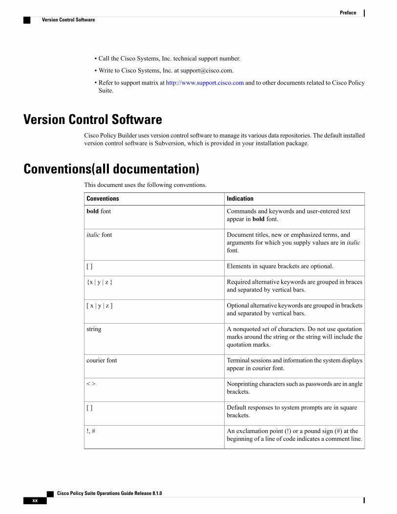
Conventions(all documentation)This document uses the following conventions.
IndicationConventions
Commands and keywords and user-entered textappear in bold font.
bold font
Document titles, new or emphasized terms, andarguments for which you supply values are in italicfont.
italic font
Elements in square brackets are optional.[ ]
Required alternative keywords are grouped in bracesand separated by vertical bars.
{x | y | z }
Optional alternative keywords are grouped in bracketsand separated by vertical bars.
[ x | y | z ]
A nonquoted set of characters. Do not use quotationmarks around the string or the string will include thequotation marks.
string
Terminal sessions and information the system displaysappear in courier font.
courier font
Nonprinting characters such as passwords are in anglebrackets.
< >
Default responses to system prompts are in squarebrackets.
[ ]
An exclamation point (!) or a pound sign (#) at thebeginning of a line of code indicates a comment line.
!, #
Cisco Policy Suite Operations Guide Release 8.1.0xx
PrefaceVersion Control Software
Means reader take note. Notes contain helpful suggestions or references to material not covered in themanual.
Note
Means reader be careful. In this situation, you might perform an action that could result in equipmentdamage or loss of data.
Caution
IMPORTANT SAFETY INSTRUCTIONS.
Means danger. You are in a situation that could cause bodily injury. Before you work on any equipment, beaware of the hazards involved with electrical circuitry and be familiar with standard practices for preventingaccidents. Use the statement number provided at the end of each warning to locate its translation in thetranslated safety warnings that accompanied this device.
SAVE THESE INSTRUCTIONS
Provided for additional information and to comply with regulatory and customer requirements.Warning
Obtaining Documentation and Submitting a Service RequestFor information on obtaining documentation, using the Cisco Bug Search Tool (BST), submitting a servicerequest, and gathering additional information, see What’s New in Cisco Product Documentation at:
http://www.cisco.com/c/en/us/td/docs/general/whatsnew/whatsnew.html
Subscribe toWhat’s New in Cisco Product Documentation, which lists all new and revised Cisco technicaldocumentation as an RSS feed and delivers content directly to your desktop using a reader application. TheRSS feeds are a free service.
Cisco Policy Suite Operations Guide Release 8.1.0 xxi
PrefaceObtaining Documentation and Submitting a Service Request
Cisco Policy Suite Operations Guide Release 8.1.0xxii
PrefaceObtaining Documentation and Submitting a Service Request
C H A P T E R 1Cisco Policy Server Operations
• Starting and Stopping, page 1
• Recovering After a Power Outage, page 7
• Multi-user Policy Builder, page 10
• Control Center Access, page 12
• Backing Up and Restoring, page 16
• Adding or Replacing Hardware, page 16
• Adding a New Disk, page 17
• Publishing Data, page 19
• HAProxy, page 19
• Unified API Security: Access Privileges, page 21
• Enabling Unified API Access on HTTP Port 8080, page 23
• Enable SSL, page 25
• Use of Audit, page 25
• Policy Tracing and Execution Analyzer, page 39
• TACACS+, page 42
• Porting All-In-One Policy Builder Configuration to HA, page 45
Starting and StoppingThis section describes several start and stop tasks for the Cisco Policy Server.
• Starting VMs Using VMware GUI, on page 2
• Restarting the Cisco Policy Server, on page 2
• Shutting Down the Cisco Policy Server Nodes, on page 5
• Switching Active and Standby Load Balancers, on page 9
Cisco Policy Suite Operations Guide Release 8.1.0 1

Starting VMs Using VMware GUI
Step 1 Start a VMware vSphere session.Step 2 Right-click the VM and select Power > Power On as shown.
Figure 1: Powering on a VM
Step 3 After the VM has started, log in to the VM from Cluster Manager and verify that the processes are running.
Restarting the Cisco Policy ServerCPS is composed of a cluster of nodes and services. This section describes how to restart the different servicesrunning on various CPS nodes.
Restarting Database ServicesEach database port and configuration is defined in the /etc/broadhop/mongoConfig.cfg file.
The scripts that start/stop the database services can be found in the /etc/init.d/ directory on the CPS nodes.
Cisco Policy Suite Operations Guide Release 8.1.02
Cisco Policy Server OperationsStarting VMs Using VMware GUI
To stop and start a database, login to each Session Manager Server and execute the following commands. Forexample, to restart the sessionmgr 27717 DB, execute:service sessionmgr-27717 stopservice sessionmgr-27717 start
or:
service sessionmgr-27717 restart
It is important not to stop and start all of the databases in the same replica set at the same time. As a bestpractice, stop and start databases one at a time to avoid service interruption.
Note
Restarting QNS Services
Restarting All QNS Services
To restart all qns services on all VMs, execute the following from the Cluster Manager:
/var/qps/bin/control/restartall.sh
This script only restarts the qns services. It does not restart any other services.Note
Use summaryall.sh or statusall.sh to see details about these services.
Restarting All QNS Services on a Specific VM
To restart all qns services on a single CPS VM, execute the following from the Cluster Manager:
/var/qps/bin/control/restartqns.sh <hostname>
where <hostname> is the CPS node name of the VM (qns01, qns02, lb01, pcrfclient01, etc.).
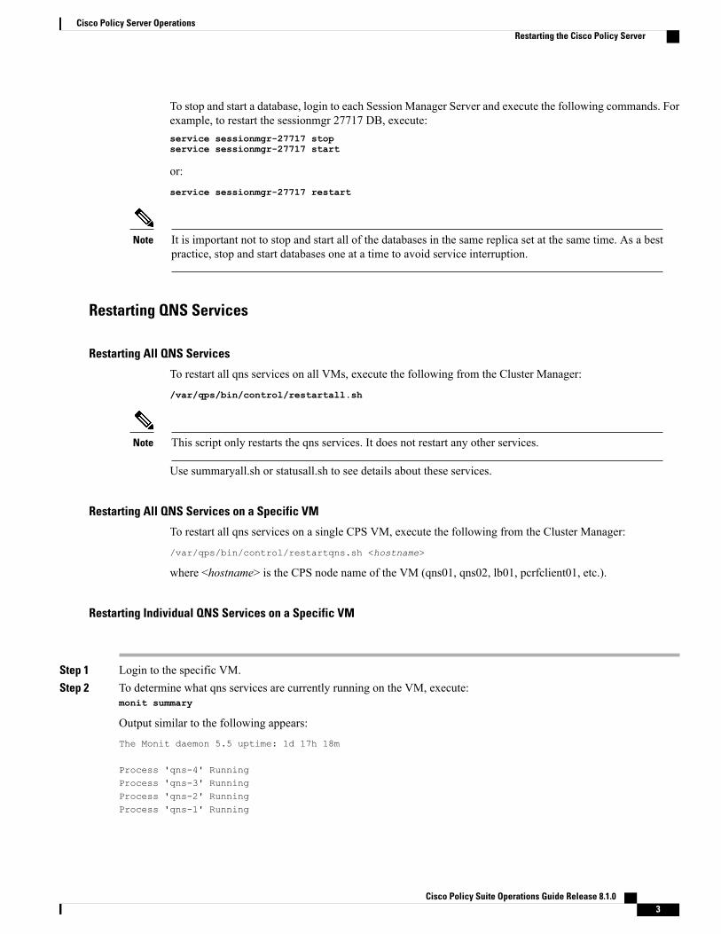
Restarting Individual QNS Services on a Specific VM
Step 1 Login to the specific VM.Step 2 To determine what qns services are currently running on the VM, execute:
monit summary
Output similar to the following appears:
The Monit daemon 5.5 uptime: 1d 17h 18m
Process 'qns-4' RunningProcess 'qns-3' RunningProcess 'qns-2' RunningProcess 'qns-1' Running
Cisco Policy Suite Operations Guide Release 8.1.0 3
Cisco Policy Server OperationsRestarting the Cisco Policy Server

Step 3 Execute the following commands to stop and start the individual qns process:monit stop qns-<instance id>monit start qns-<instance id>
Restarting Services Managed by MonitThe Monit service manages many of the services on each CPS VM.
To see a list of services managed by monit on a VM, log in to the specific VM and execute:
monit summary
To stop and start all services managed by monit, log in to the specific VM and execute the following commands:monit stop allmonit start all
To stop and start a specific service managed by monit, log in to the specific VM and execute the followingcommands:monit stop <service_name>monit start <service_name>
where <service_name> is the name as shown in the output of the monit summary command.
Restarting Other Services
Restarting Subversion
To restart Subversion (SVN) on pcrfclient nodes, execute:
service httpd restart
Restarting Policy Builder
To restart Policy Builder on pcrfclient nodes (pcrfclient01/pcrfclient02), execute:monit stop qns-2monit start qns-2
Restarting Control Center
To restart Control Center on pcrfclient nodes (pcrfclient01/pcrfclient02), execute:monit stop qns-1monit start qns-1
Cisco Policy Suite Operations Guide Release 8.1.04
Cisco Policy Server OperationsRestarting the Cisco Policy Server

Restarting Services on Policy Director/Load Balancer (lb01 and lb02)The following commands are used to restart the services on the Policy Director (Load Balancer) nodes only(lb01 and lb02).
Step 1 Login to lb01/lb02.Step 2 To restart the service that controls the virtual IPs (lbvip01 and lbvip02 are virtual IP addresses shared between lb01 and
lb02 for High Availability), execute the following command:service corosync restart
Step 3 To restart the service that balances and forwards IP traffic (port forwarding service) from lb01/lb02 to other CPS nodes,execute:service haproxy restart
Shutting Down the Cisco Policy Server NodesThe following sections describe the commands to shut down the Cisco Policy Server nodes:
• lb or qns Nodes, on page 5
• pcrfclient Nodes, on page 6
• sessionmgr Nodes, on page 6
lb or qns Nodes
Step 1 SSH to the lbxx or qnsxx node from Cluster Manager:ssh lbxx/qnsxx
Step 2 Stop all CPS processes on the node:/usr/bin/monit stop all
Step 3 Check the status of all the processes. Verify that all processes are stopped before proceeding./usr/bin/monit status all
Step 4 Stop the monit process:service monit stop
Step 5 Shut down lbxx/qnsxx:shutdown -h now
Cisco Policy Suite Operations Guide Release 8.1.0 5
Cisco Policy Server OperationsShutting Down the Cisco Policy Server Nodes
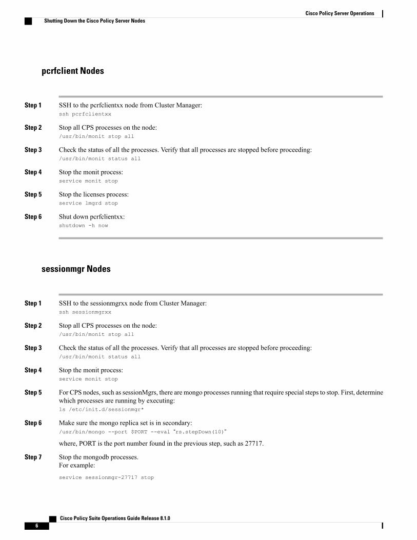
pcrfclient Nodes
Step 1 SSH to the pcrfclientxx node from Cluster Manager:ssh pcrfclientxx
Step 2 Stop all CPS processes on the node:/usr/bin/monit stop all
Step 3 Check the status of all the processes. Verify that all processes are stopped before proceeding:/usr/bin/monit status all
Step 4 Stop the monit process:service monit stop
Step 5 Stop the licenses process:service lmgrd stop
Step 6 Shut down pcrfclientxx:shutdown -h now
sessionmgr Nodes
Step 1 SSH to the sessionmgrxx node from Cluster Manager:ssh sessionmgrxx
Step 2 Stop all CPS processes on the node:/usr/bin/monit stop all
Step 3 Check the status of all the processes. Verify that all processes are stopped before proceeding:/usr/bin/monit status all
Step 4 Stop the monit process:service monit stop
Step 5 For CPS nodes, such as sessionMgrs, there are mongo processes running that require special steps to stop. First, determinewhich processes are running by executing:ls /etc/init.d/sessionmgr*
Step 6 Make sure the mongo replica set is in secondary:/usr/bin/mongo --port $PORT --eval “rs.stepDown(10)”
where, PORT is the port number found in the previous step, such as 27717.
Step 7 Stop the mongodb processes.For example:
service sessionmgr-27717 stop
Cisco Policy Suite Operations Guide Release 8.1.06
Cisco Policy Server OperationsShutting Down the Cisco Policy Server Nodes
Step 8 Shut down sessionmgrxx:shutdown -h now
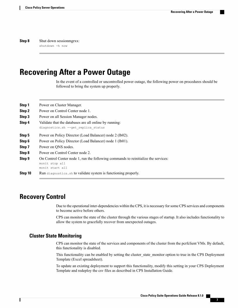
Recovering After a Power OutageIn the event of a controlled or uncontrolled power outage, the following power on procedures should befollowed to bring the system up properly.
Step 1 Power on Cluster Manager.Step 2 Power on Control Center node 1.Step 3 Power on all Session Manager nodes.Step 4 Validate that the databases are all online by running:
diagnostics.sh --get_replica_status
Step 5 Power on Policy Director (Load Balancer) node 2 (lb02).Step 6 Power on Policy Director (Load Balancer) node 1 (lb01).Step 7 Power on QNS nodes.Step 8 Power on Control Center node 2.Step 9 On Control Center node 1, run the following commands to reinitialize the services:
monit stop allmonit start all
Step 10 Run diagnostics.sh to validate system is functioning properly.
Recovery ControlDue to the operational inter-dependencies within the CPS, it is necessary for someCPS services and componentsto become active before others.
CPS can monitor the state of the cluster through the various stages of startup. It also includes functionality toallow the system to gracefully recover from unexpected outages.
Cluster State MonitoringCPS can monitor the state of the services and components of the cluster from the pcrfclient VMs. By default,this functionality is disabled.
This functionality can be enabled by setting the cluster_state_monitor option to true in the CPS DeploymentTemplate (Excel spreadsheet).
To update an existing deployment to support this functionality, modify this setting in your CPS DeploymentTemplate and redeploy the csv files as described in CPS Installation Guide.
Cisco Policy Suite Operations Guide Release 8.1.0 7
Cisco Policy Server OperationsRecovering After a Power Outage

This monitoring system reports the state of the system as an integer value as described in the following table:
Table 1: Cluster Manager Monitoring
ValuesDescriptionClusterState
The system will report ‘0’ until both conditions havebeen met under ‘1’: lbvip02 is UP AND DBs areaccessible.
Various systems can be coming online while a ‘0’ stateis being reported and does not automatically indicatean error.
Even if the system cannot proceed to ‘1’ state, PolicyBuilder and Control Center UIs should be available inorder to manage or troubleshoot the system.
unknown state/pre-inspection state0
All backend databases must be available and thelbvip02 interface must be UP for the system to reportthis state.
lbvip02 is alive
and
all DBs in/etc/broadhop/mongoConfig.cfghave an accessible primary
1
Backend qns processes access lbvip02 on this port.When this port is activated, it indicates that qnsprocesses can proceed to start.
lbvip02 port 61616 is accepting TCPconnections
2
Once sufficient capacity is available from the backendprocesses, the diameter protocol endpoint processesare allowed to start.
at least 50% of backend QNS processesare alive
3
The current cluster state is reported in the following file on the pcrfclient:/var/run/broadhop.cluster_state
The determine_cluster_state command logs output of the cluster state monitoring process into/var/log/broadhop/determine_cluster_state.log.
Controlled StartupIn addition to the monitoring functionality, there is new functionality which uses the cluster state to regulatethe startup of some of the CPS services pending the appropriate state of the cluster.
By default this functionality is disabled. It can be enabled for the entire CPS cluster, or for troubleshootingpurposes can be enabled or disabled on a per-VM basis.
Cluster State Monitoring must be enabled for Controlled Startup to function.Note
Cisco Policy Suite Operations Guide Release 8.1.08
Cisco Policy Server OperationsRecovery Control
Enable/Disable For All VMs in Cluster
The Controlled Startup functionality is enabled by the presence of the /etc/broadhop/cluster_statefile.
To enable this feature on all CPS VMs in the cluster, execute the following commands on the Cluster ManagerVM to create this file and to use the syncconfig.sh script to push those changes out to the other VMs.touch /etc/broadhop/cluster_statesyncconfig.shTo disable this feature on all VMs in the cluster, remove the cluster_state file on the Cluster Manager VMand sync the configuration:rm /etc/broadhop/cluster_statesyncconfig.sh
Enable/Disable For Specific VM
To enable this feature on a specific VM, create a /etc/broadhop/cluster_state file on the VM:
touch /etc/broadhop/cluster_state
To disable this feature again on a specific VM, delete the /etc/broadhop/cluster_state file on theVM:
rm /etc/broadhop/cluster_state
This is temporary measure and should only be used for diagnostic purposes. Local modifications to a VMcan be overwritten under various circumstances, such as running syncconfig.sh.
Note
Switching Active and Standby Load BalancersIn CPS, the active and standby strategy applies only to the load balancers. The following are the two loadbalancers in the system:
• lb01
• lb02
Determining the Active Load Balancer
Step 1 Log in to the pcrfclient01 VM.Step 2 Run the following command to SSH to the active load balancer (typically lb01):
ssh lbvip01
Step 3 You can also confirm an active load balancer by ensuring it has the virtual IP (VIP) associated with it by running thefollowing command:ifconfig -a
If you see the eth0:0 or eth1:0 interfaces present in the list and marked as “UP” then that is the active LB.
Cisco Policy Suite Operations Guide Release 8.1.0 9
Cisco Policy Server OperationsSwitching Active and Standby Load Balancers
For example:
eth0:0 Link encap:Ethernet HWaddr 00:0C:29:CD:7E:4Cinet addr:172.26.241.240 Bcast:172.26.241.255 Mask:255.255.254.0
--> UP BROADCAST RUNNING MULTICAST MTU:1500 Metric:1 The passive or standby load balancerwill not have active VIPs
shown in theifconfig -a output (no eth0:0 and eth1:0).
Switching Standby and Active Load Balancer
Step 1 Log in to the active Load Balancer VM. See Determining the Active Load Balancer, on page 9 for details to determinewhich LB is active.
Step 2 Restart the Heartbeat service using the following command:service corosync restart
This command will force the failover of the VIP from the active load balancer to the standby load balancer.
Step 3 To confirm the switchover, SSH to the other load balancer VM and run the following command to determine if the VIPis now associated with this VM:ifconfig -a
If you see the eth0:0 or eth1:0 interfaces in the list and marked as “UP” then that is the active LB.
Multi-user Policy BuilderMultiple users can be logged into Policy Builder at the same time.
In the event that two users attempt to make changes on same screen and one user saves their changes to theclient repository, the other user may receive errors. In such cases the user must return to the login page, revertthe configuration, and repeat their changes.
This section covers the following topics:
• Create Users, on page 11
• Revert Configuration, on page 11
Cisco Policy Suite Operations Guide Release 8.1.010
Cisco Policy Server OperationsMulti-user Policy Builder
Create Users
Step 1 Log in to the Cluster Manager.Step 2 Add a user to CPS by executing:
adduser.sh
Step 3 When prompted for the user’s group, set ‘qns-svn’ for read-write permissions or ‘qns-ro’ for read-only permissions.
• To check if a user already exists, login in as root and enter su username.
• To check a user’s ‘groups’, enter groups username.
• To change a user’s password, use the change_passwd.sh command.
Refer to CPS Commands, on page 109 for more information about these commands.
Revert ConfigurationThe user can revert the configuration if changes since the last publish/save to client repository are not wanted.
This can also be necessary in the case of a ‘syn conflict’ error where both pcrfclient01 and pcrfclient02 are inuse at the same time by different users and publish/save to client repository changes to the same file. Theeffect of reverting changes is that all changes since the publish/save to client repository will be undone.
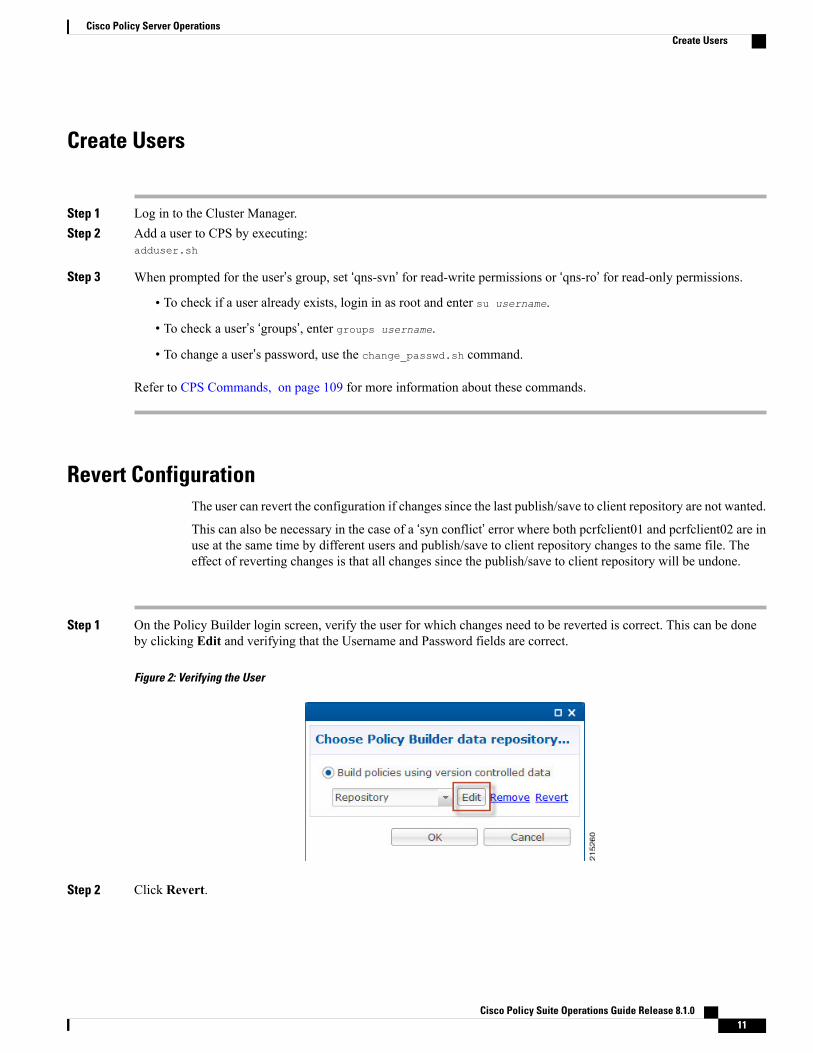
Step 1 On the Policy Builder login screen, verify the user for which changes need to be reverted is correct. This can be doneby clicking Edit and verifying that the Username and Password fields are correct.
Figure 2: Verifying the User
Step 2 Click Revert.
Cisco Policy Suite Operations Guide Release 8.1.0 11
Cisco Policy Server OperationsCreate Users

The following confirmation dialog opens.
Figure 3: Revert Confirmation Message
Step 3 Click OK to revert back to the earlier configuration. The following dialog confirms that the changes are revertedsuccessfully.
Figure 4: Success Confirmation Message
Control Center AccessAfter the installation is complete, you need to configure the Control Center access. This is designed to givethe customer a customized Control Center username.
Add a Control Center User
Step 1 Log in to Cluster Manager VM.Step 2 Execute the following script to add a Control Center user.
/var/qps/bin/support/adduser.sh
To add a user with 'read/write' access to Control Center, their group should be 'qns'. To add a user with 'read'access to Control Center, their group should be 'qns-ro'.
Note
Cisco Policy Suite Operations Guide Release 8.1.012
Cisco Policy Server OperationsControl Center Access

Example:
/var/qps/bin/support/adduser.shEnter username: usernameEnter group for the user: groupnameEnter password: passwordRe-enter password: password
This example adds username to all the VMs in the cluster.
Update Control Center MappingThis section describes updating Control Center mapping of read-write/read-only to user groups (Default: qnsand qns-ro respectively)
Step 1 Login to Cluster Manager VM.Step 2 Update /etc/broadhop/authentication-provider.xml to include the group mapping for the group you
want to use.Make sure that this group exists on at least the qns VMs or adding users will fail due to no group available (thereshould be an entry in /etc/group).
In the following example, the 'test' group has been added as an read-write mapping for Control Center - updatedline in bold:
<beans:beans xmlns="http://www.springframework.org/schema/security"xmlns:beans="http://www.springframework.org/schema/beans"xmlns:xsi="http://www.w3.org/2001/XMLSchema-instance"xsi:schemaLocation="http://www.springframework.org/schema/beans
classpath:/org/springframework/beans/factory/xml/spring-beans-3.0.xsdhttp://www.springframework.org/schema/security
classpath:/org/springframework/security/config/spring-security-3.0.xsd"><beans:bean id="authenticationProvider"class="com.broadhop.ui.security.server.pam.PamAuthenticationProvider">
<!-- change the key value to be the customer's role that maps to the cisco role. --><beans:property name="roleMap"><beans:map><beans:entry key="qns" value="ROLE_SUMADMIN" /><beans:entry key="test" value="ROLE_SUMADMIN" /><beans:entry key="qns-ro" value="ROLE_READONLY" />
</beans:map></beans:property>
</beans:bean>
<authentication-manager><authentication-provider ref="authenticationProvider" />
</authentication-manager>
</beans:beans>
Note
Cisco Policy Suite Operations Guide Release 8.1.0 13
Cisco Policy Server OperationsUpdate Control Center Mapping

Step 3 Run syncconfig.sh to put this file on all VMs.Step 4 Restart the CPS system, so that the changes done above are reflected in the VMs:
restartall.sh
To add a new user to Control Center and specify the group you've specified in the configuration file above, refer to Adda Control Center User, on page 12.
Multiple Concurrent User SessionsCPS Control Center supports session limits per user. If the user exceeds the configured session limit, they arenot allowed to login. CPS also provides notifications to the user when other users are already logged in.
When a user logs in to Control Center, a Welcome message displays at the top of the screen. A session counteris shown next to the username. This represents the number of login sessions for this user. In the followingexample, this user is logged in only once ( [1] ).
Figure 5: Welcome Message
The user can click the session counter ([1]) link to view details for the session(s), as shown below.
Figure 6: Viewing Session Details
Cisco Policy Suite Operations Guide Release 8.1.014
Cisco Policy Server OperationsMultiple Concurrent User Sessions
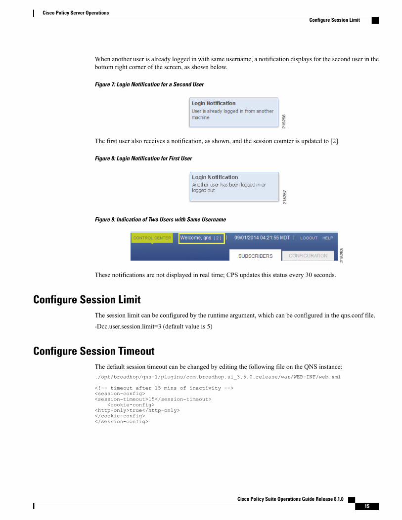
When another user is already logged in with same username, a notification displays for the second user in thebottom right corner of the screen, as shown below.
Figure 7: Login Notification for a Second User
The first user also receives a notification, as shown, and the session counter is updated to [2].
Figure 8: Login Notification for First User
Figure 9: Indication of Two Users with Same Username
These notifications are not displayed in real time; CPS updates this status every 30 seconds.
Configure Session LimitThe session limit can be configured by the runtime argument, which can be configured in the qns.conf file.
-Dcc.user.session.limit=3 (default value is 5)
Configure Session TimeoutThe default session timeout can be changed by editing the following file on the QNS instance:./opt/broadhop/qns-1/plugins/com.broadhop.ui_3.5.0.release/war/WEB-INF/web.xml
<!-- timeout after 15 mins of inactivity --><session-config><session-timeout>15</session-timeout>
<cookie-config><http-only>true</http-only></cookie-config></session-config>
Cisco Policy Suite Operations Guide Release 8.1.0 15
Cisco Policy Server OperationsConfigure Session Limit

The same timeout value must be entered on all qns instances.
When the number of sessions of the user exceeds the session limit, the user is not allowed to log in andreceives the message “Max session limit per user exceed!”
Note
Important NotesIf a user does not log out and then closes their browser, the session remains alive on the server until the sessiontimes out. When the session time out occurs, the session is deleted from the memcached server. The defaultsession timeout is 15 minutes. This is the idle time after which session is automatically deleted.
When a QNS instance is restarted, all user/session details are cleared.
When the memcached server is restarted but not the QNS instances, all http sessions on the QNS instance areinvalidated. In this case user is asked to re-login and after that new session is created.
Backing Up and RestoringAs a part of routine operations, it is important to make backups so that in the event of failures, the system canbe restored. Do not store backups on system nodes.
For detailed information about backup and restore procedures, see the Cisco Policy Suite Backup and RestoreGuide.
Adding or Replacing HardwareHardware replacement is usually performed by the hardware vendor with whom your company holds a supportcontract.
Hardware support is not provided by Cisco. The contact persons and scheduling for replacing hardware ismade by your company.
Before replacing hardware, always make a backup. See the Cisco Policy Suite Backup and Restore Guide.
Unless you have a readily available backup solution, use VMware Data Recovery. This solution, provided byVMware under a separate license, is easily integrated into your CPS environment.
Cisco Policy Suite Operations Guide Release 8.1.016
Cisco Policy Server OperationsImportant Notes

The templates you download from the Cisco repository are partially pre-configured but require furtherconfiguration. Your Cisco technical representative can provide you with detailed instructions.
You can download the VMware software and documentation from the following location:
http://www.vmware.com/
Note
Adding a New DiskThis section describes the procedures needed to add a new disk to a 7.x VM.
Prerequisites• All the VMs were created using the 7.x deployment process.
• This procedure assumes the datastore that will be used to have the virtual disk has sufficient space toadd the virtual disk.
• This procedure assumes the datastore has been mounted to the VMware ESX server, regardless of thebackend NAS device (SAN or iSCSI, etc).
ESX Server Configuration
Step 1 Login to the ESX server shell, and make sure the datastore has enough space:vmkfstools -c 4g /vmfs/volumes/datastore_name/VMNAME/xxxx.vmdk -d thin
Step 2 Execute vim-cmd vmsvc/getallvms to get the vmid of the VM where the disk needs to be added.Vmid Name File Guest OS Version Annotation173 vminstaller-AIO [datastore5] vminstaller-AIO/vminstaller-AIO.vmx centos64Guest vmx-08
Step 3 Assign the disk to the VM. xxx. is the disk name, warning, the 0 and 1 indicate the SCSI device number. In this example,let us assume that this is the second disk:vim-cmd vmsvc/device.diskaddexisting vmid /vmfs/volumes/path to xxxx.vmdk 0 1
Cisco Policy Suite Operations Guide Release 8.1.0 17
Cisco Policy Server OperationsAdding a New Disk
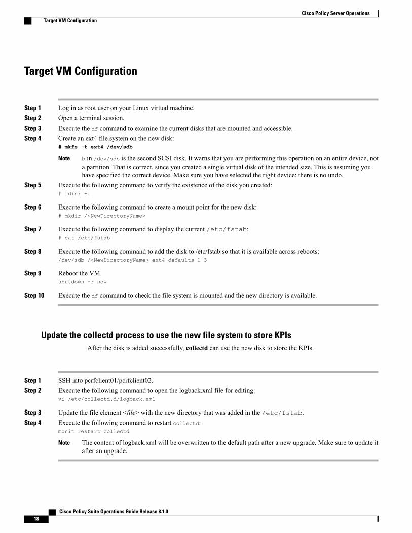
Target VM Configuration
Step 1 Log in as root user on your Linux virtual machine.Step 2 Open a terminal session.Step 3 Execute the df command to examine the current disks that are mounted and accessible.Step 4 Create an ext4 file system on the new disk:
# mkfs -t ext4 /dev/sdb
b in /dev/sdb is the second SCSI disk. It warns that you are performing this operation on an entire device, nota partition. That is correct, since you created a single virtual disk of the intended size. This is assuming youhave specified the correct device. Make sure you have selected the right device; there is no undo.
Note
Step 5 Execute the following command to verify the existence of the disk you created:# fdisk -l
Step 6 Execute the following command to create a mount point for the new disk:# mkdir /<NewDirectoryName>
Step 7 Execute the following command to display the current /etc/fstab:# cat /etc/fstab
Step 8 Execute the following command to add the disk to /etc/fstab so that it is available across reboots:/dev/sdb /<NewDirectoryName> ext4 defaults 1 3
Step 9 Reboot the VM.shutdown -r now
Step 10 Execute the df command to check the file system is mounted and the new directory is available.
Update the collectd process to use the new file system to store KPIsAfter the disk is added successfully, collectd can use the new disk to store the KPIs.
Step 1 SSH into pcrfclient01/pcrfclient02.Step 2 Execute the following command to open the logback.xml file for editing:
vi /etc/collectd.d/logback.xml
Step 3 Update the file element <file> with the new directory that was added in the /etc/fstab.Step 4 Execute the following command to restart collectd:
monit restart collectd
The content of logback.xml will be overwritten to the default path after a new upgrade. Make sure to update itafter an upgrade.
Note
Cisco Policy Suite Operations Guide Release 8.1.018
Cisco Policy Server OperationsTarget VM Configuration

Publishing DataThis section describes publishing Cisco Policy Builder data to the Cisco Policy Server. Publishing data occursin the Cisco Policy Builder client interface, but affects the Cisco Policy Server. Refer to the CPS MobileConfiguration Guide for steps to publish data to the server.
Cisco Policy Builder manages data stored in two areas:
• The Client Repository stores data captured from the Policy Builder GUI in Subversion. This is a placewhere trial configurations can be developed and saved without affecting the operation of the Cisco PolicyBuilder server data.
The default URL is http://pcrfclient01/repos/configuration.
• The Server Repository is where a ‘copy’ of the client repository is created/updated and where the CPSServer picks up changes. This is done on “Publish” from Policy Builder.
Publishing will also do a “Save to Client Repository” to ensure the Policy Builder andServer configurations are not out of sync.
Note
The default URL is http://pcrfclient01/repos/run.
HAProxyHAProxy is an opensource load balancer used in High Availability (HA) and Geographic Redundancy (GR)CPS deployments. It is used by the CPS Load Balancers to forward IP traffic from lb01/lb02 to other CPSnodes. HAProxy runs on the active Load Balancer (LB) VM.
Documentation for HAProxy is available at http://www.haproxy.org/#docs.
HAProxy Service Operations
DiagnosticsFor a general diagnostics check of the HAProxy service, run the following command from any VM in thecluster (except sessionmgr):
diagnostics.sh --ha_proxyQPS Diagnostics Multi-Node Environment---------------------------Ping Check for qns01...[PASS]Ping Check for qns02...[PASS]Ping Check for qns03...[PASS]Ping Check for qns04...[PASS]Ping Check for lb01...[PASS]Ping Check for lb02...[PASS]Ping Check for sessionmgr01...[PASS]Ping Check for sessionmgr02...[PASS]Ping Check for sessionmgr03...[PASS]Ping Check for sessionmgr04...[PASS]Ping Check for pcrfclient01...[PASS]
Cisco Policy Suite Operations Guide Release 8.1.0 19
Cisco Policy Server OperationsPublishing Data

Ping Check for pcrfclient02...[PASS]HA Multi-Node Environment---------------------------Checking HAProxy status...[PASS]
Service CommandsThe following commands must be issued from the lb01 or lb02 VM.
To check the status of the HAProxy services, run the following command:
service haproxy status
[root@host-lb01 ~]# service haproxy statushaproxy (pid 10005) is running...
To stop the HAProxy service, run the following command:
service haproxy stop
To restart the HAProxy service, run the following command:
service haproxy restart
HAProxy StatisticsTo view HAProxy statistics, open a browser and navigate to the following URL:
http://<lbvip01>:5540/haproxy?stats
Customizing HAProxyTo customize HAProxy in your CPS deployment, you must make changes to the HAProxy configuration fileson the Cluster Manager and then push the changes out to the Load Balancer VMs.
Once deployed, the HAProxy configuration files are stored locally on the Load Balancer VMs at/etc/haproxy/haproxy.cfg.
Step 1 Log in to the Cluster Manager.Step 2 Create a backup of the HAProxy configuration file before continuing:
cp /var/qps/install/current/puppet/modules/qps/templates/etc/haproxy/haproxy.cfg
/var/qps/install/current/puppet/modules/qps/templates/etc/haproxy/haproxy.cfg-bak-<date>
Step 3 Edit the following file as needed:/var/qps/install/current/puppet/modules/qps/templates/etc/haproxy/haproxy.cfg
By default, the logging level is set as error (err), as shown in the following line:
log 127.0.0.1 local1 err
The log level can be adjusted to any of the following log levels as needed:
emerg alert crit err warning notice info debug
Cisco Policy Suite Operations Guide Release 8.1.020
Cisco Policy Server OperationsCustomizing HAProxy
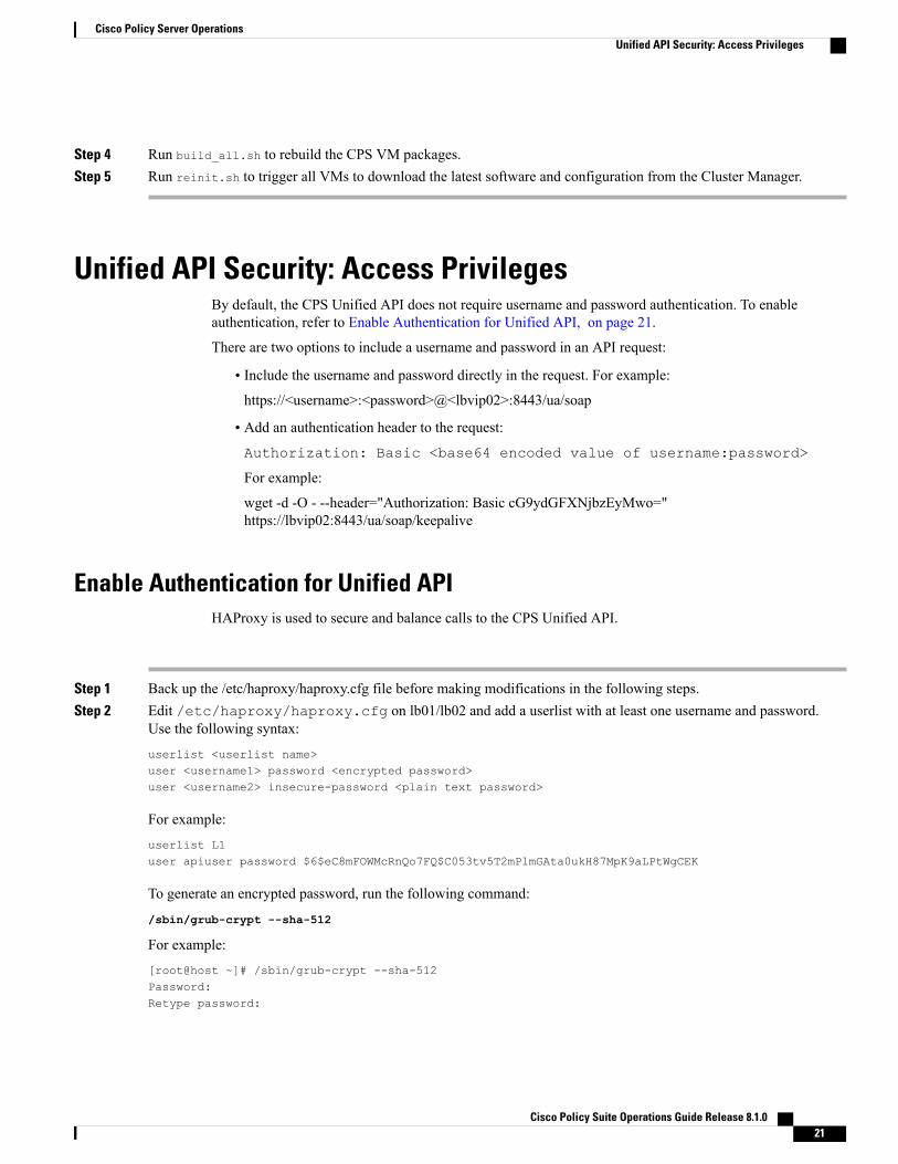
Step 4 Run build_all.sh to rebuild the CPS VM packages.Step 5 Run reinit.sh to trigger all VMs to download the latest software and configuration from the Cluster Manager.
Unified API Security: Access PrivilegesBy default, the CPS Unified API does not require username and password authentication. To enableauthentication, refer to Enable Authentication for Unified API, on page 21.
There are two options to include a username and password in an API request:
• Include the username and password directly in the request. For example:https://<username>:<password>@<lbvip02>:8443/ua/soap
• Add an authentication header to the request:Authorization: Basic <base64 encoded value of username:password>
For example:
wget -d -O - --header="Authorization: Basic cG9ydGFXNjbzEyMwo="https://lbvip02:8443/ua/soap/keepalive
Enable Authentication for Unified APIHAProxy is used to secure and balance calls to the CPS Unified API.
Step 1 Back up the /etc/haproxy/haproxy.cfg file before making modifications in the following steps.Step 2 Edit /etc/haproxy/haproxy.cfg on lb01/lb02 and add a userlist with at least one username and password.
Use the following syntax:
userlist <userlist name>user <username1> password <encrypted password>user <username2> insecure-password <plain text password>
For example:
userlist L1user apiuser password $6$eC8mFOWMcRnQo7FQ$C053tv5T2mPlmGAta0ukH87MpK9aLPtWgCEK
To generate an encrypted password, run the following command:
/sbin/grub-crypt --sha-512
For example:
[root@host ~]# /sbin/grub-crypt --sha-512Password:Retype password:
Cisco Policy Suite Operations Guide Release 8.1.0 21
Cisco Policy Server OperationsUnified API Security: Access Privileges

<encrypted password output>
Step 3 Edit /etc/haproxy/haproxy.cfg on lb01/lb02 to configure HAProxy to require authentication. Add the following4 lines to the haproxy.cfg file:acl validateAuth http_auth(<userlist_name>)acl unifiedAPI path_beg -i /ua/soaphttp-request allow if !unifiedAPIhttp-request auth unless validateAuth
The userlist created in Step 2 needs to be mapped with the acl in the following line:
acl validateAuth http_auth(<userlist name>)
For example:
frontend https-apidescription Unified APIbind lbvip01:8443 ssl crt /etc/ssl/certs/quantum.pemdefault_backend api_serversreqadd X-Forwarded-Proto:\ https if { ssl_fc }backend api_serversmode httpbalance roundrobinoption httpcloseoption abortoncloseoption httpchk GET /ua/soap/keepaliveserver qns01_A qns01:8080 check inter 30sserver qns02_A qns02:8080 check inter 30sserver qns03_A qns03:8080 check inter 30sserver qns04_A qns04:8080 check inter 30sacl validateAuth http_auth(L1)acl unifiedAPI path_beg -i /ua/soaphttp-request allow if !unifiedAPIhttp-request auth unless validateAuthThe configuration above applies authentication on context /ua/soap, which is the URL path of the Unified API.
The haproxy.cfg file is generated by the puppet tool. Any manual changes to the file in lb01/lb02 would bereverted if the pupdate or vm-init scripts are run.
Note
WSDL and Schema DocumentationIn order to access the Unified API WSDL while using authentication change the following line:
acl unifiedAPI path_beg -i /ua/soap
to
acl unifiedAPI path_beg -i /ua/.
The default address for the WSDL is https//<lbvip01>8443/ua/wsdl/UnifiedApi.wsdl
The Unified API contains full documentation in an html format that is compatible with all major browsers.
The default address is https//<lbvip01>8443/ua/wsdl/UnifiedApi.xsd
Cisco Policy Suite Operations Guide Release 8.1.022
Cisco Policy Server OperationsEnable Authentication for Unified API

Run the about.sh command from the Cluster Manager to display the actual addresses as configured inyour deployment.
Note
Enabling Unified API Access on HTTP Port 8080CPS 7.x onward uses HTTPS on port 8443 for Unified API access. To enable HTTP support (like pre-7.0)on port 8080, perform the following steps:
Make sure to open port 8080 if firewall is used on the setup.Note
Step 1 Create the following directories (ignore File exists error), on Cluster Manager:/bin/mkdir -p /var/qps/env_config/modules/custom/templates/etc/haproxy/bin/mkdir -p /var/qps/env_config/modules/custom/templates/etc/monit.d/bin/mkdir -p /var/qps/env_config/nodes
Step 2 Create the file/var/qps/env_config/modules/custom/templates/etc/haproxy/haproxy-soaphttp.erbwiththe following contents on Cluster Manager:
• Change XXXX with the Unified API interface hostname or IP
• In this example, we are adding 10 QNS servers. You can add/remove the number of QNS servers depending onyour network requirements.
globaldaemonnbproc 1 # number of processing coresstats socket /tmp/haproxy-soaphttp
defaultstimeout client 60000ms # maximum inactivity time on the client sidetimeout server 180000ms # maximum inactivity time on the server sidetimeout connect 60000ms # maximum time to wait for a connection attempt to a server to
succeed
log 127.0.0.1 local1 err
listen pcrf_proxy XXXX:8080 ----------- > where, XXXX, is Unified API interface hostname or IPmode httpbalance roundrobinoption httpcloseoption abortoncloseoption httpchk GET /ua/soap/KeepAliveserver qns01_A qns01:8080 check inter 30sserver qns02_A qns02:8080 check inter 30sserver qns03_A qns03:8080 check inter 30sserver qns04_A qns04:8080 check inter 30s
Cisco Policy Suite Operations Guide Release 8.1.0 23
Cisco Policy Server OperationsEnabling Unified API Access on HTTP Port 8080

server qns05_A qns05:8080 check inter 30sserver qns06_A qns06:8080 check inter 30sserver qns07_A qns07:8080 check inter 30sserver qns08_A qns08:8080 check inter 30sserver qns09_A qns09:8080 check inter 30sserver qns10_A qns10:8080 check inter 30s
Step 3 Create the file /var/qps/env_config/modules/custom/templates/etc/monit.d/haproxy-soaphttpwith the following contentson Cluster Manager:check process haproxy-soaphttp with pidfile /var/run/haproxy-soaphttp.pidstart = "/etc/init.d/haproxy-soaphttp start"stop = "/etc/init.d/haproxy-soaphttp stop"
Step 4 Create or modify the /var/qps/env_config/nodes/lb.yaml file with the following contents on Cluster Manager:If the file exists then just add custom::soap_http:
classes:qps::roles::lb:custom::soap_http:
Step 5 Create the file /var/qps/env_config/modules/custom/manifests/soap_http.ppwith the followingcontents on Cluster Manager.Change ethX with the Unified API IP interface like eth0/eth1/eth2.
class custom::soap_http($haproxytype = "-soaphttp",
){service { "haproxy-soaphttp":enable => false,require => [Package [ "haproxy" ],File ["/etc/haproxy/haproxy-soaphttp.cfg"],
File['/etc/init.d/haproxy-soaphttp'], Exec["sysctl_refresh"]],}file { "/etc/init.d/haproxy-soaphttp":owner => "root",group => "root",content => template('qps/etc/init.d/haproxy'),require => Package [ "haproxy" ],notify => Service['haproxy-soaphttp'],mode => 0744
}file { "/etc/haproxy/haproxy-soaphttp.cfg":owner => "root",group => "root",content => template('custom/etc/haproxy/haproxy-soaphttp.erb'),require => Package [ "haproxy" ],notify => Service['haproxy-soaphttp'],
}file { "/etc/monit.d/haproxy-soaphttp":content => template("custom/etc/monit.d/haproxy-soaphttp"),notify => Service["monit"],
}exec { "remove ckconfig for haproxy-soaphttp":command => "/sbin/chkconfig --del haproxy-soaphttp",require => [Service['haproxy-soaphttp']],
}
Cisco Policy Suite Operations Guide Release 8.1.024
Cisco Policy Server OperationsEnabling Unified API Access on HTTP Port 8080
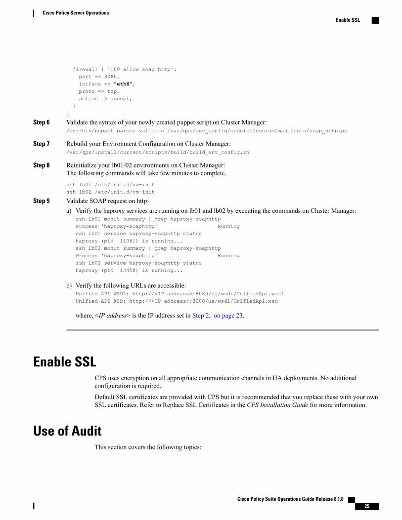
firewall { '100 allow soap http':port => 8080,iniface => "ethX",proto => tcp,action => accept,
}}
Step 6 Validate the syntax of your newly created puppet script on Cluster Manager:/usr/bin/puppet parser validate /var/qps/env_config/modules/custom/manifests/soap_http.pp
Step 7 Rebuild your Environment Configuration on Cluster Manager:/var/qps/install/current/scripts/build/build_env_config.sh
Step 8 Reinitialize your lb01/02 environments on Cluster Manager:The following commands will take few minutes to complete.
ssh lb01 /etc/init.d/vm-initssh lb02 /etc/init.d/vm-init
Step 9 Validate SOAP request on http:a) Verify the haproxy services are running on lb01 and lb02 by executing the commands on Cluster Manager:
ssh lb01 monit summary | grep haproxy-soaphttpProcess 'haproxy-soaphttp' Runningssh lb01 service haproxy-soaphttp statushaproxy (pid 11061) is running...ssh lb02 monit summary | grep haproxy-soaphttpProcess 'haproxy-soaphttp' Runningssh lb02 service haproxy-soaphttp statushaproxy (pid 13458) is running...
b) Verify the following URLs are accessible:Unified API WSDL: http://<IP address>:8080/ua/wsdl/UnifiedApi.wsdlUnified API XSD: http://<IP address>:8080/ua/wsdl/UnifiedApi.xsd
where, <IP address> is the IP address set in Step 2, on page 23.
Enable SSLCPS uses encryption on all appropriate communication channels in HA deployments. No additionalconfiguration is required.
Default SSL certificates are provided with CPS but it is recommended that you replace these with your ownSSL certificates. Refer to Replace SSL Certificates in the CPS Installation Guide for more information.
Use of AuditThis section covers the following topics:
Cisco Policy Suite Operations Guide Release 8.1.0 25
Cisco Policy Server OperationsEnable SSL

• Audit History, on page 26
• Capped Collection, on page 26
• PurgeAuditHistoryRequests, on page 27
• AuditRequests, on page 27
• Operation, on page 27
• Initial Setup, on page 27
• Read Requests, on page 28
• Querying, on page 28
• Purging, on page 29
• Purge History, on page 29
• Control Center, on page 29
• PurgeAuditHistoryRequest, on page 29
• QueryAuditHistoryRequest, on page 31
• Policy Builder, on page 32
• Reporting, on page 32
• Audit Configuration, on page 34
• Pre-configuration in Audit, on page 38
Audit HistoryThe Audit History is a way to track usage of the various GUIs and APIs it provides to the customer.
If enabled, each request is submitted to the Audit History database for historical and security purposes. Theuser who made the request, the entire contents of the request and if it is subscriber related (meaning that thereis a networkId value), all networkIds are also stored in a searchable field.
Capped CollectionBy default, the Audit History uses a 1 GB capped collection inMongo Db. The capped collection automaticallyremoves documents when the size restriction threshold is hit. The oldest document is removed as each newdocument is added. For customers whowant more than 1GB of audit data, contact the assigned CiscoAdvancedServices Engineer to get more information.
Configuration in Policy Builder is done in GB increments. It is possible to enter decimals, for example, 9.5will set the capped collection to 9.5 GB.
Cisco Policy Suite Operations Guide Release 8.1.026
Cisco Policy Server OperationsAudit History

PurgeAuditHistoryRequestsWhen using a capped collection, Mongo Db places a restriction on the database and does not allow the deletionof data from the collection. Therefore, the entire collection must be dropped and re-created. This means thatthe PurgeAuditHistory queries have no impact on capped collections.
AuditRequestsAs a consequence of the XSS defense changes to the API standard operation, any XML data sent in anAuditRequest must be properly escaped even if inside CDATA tags.
For example, <ExampleRequest>...</ExampleRequest>
For more information on AuditType, refer to Cisco Policy Suite Unified API 2.3.0 Guide.
OperationBy default, Audit History is ON but it can be turned OFF.
• ua.client.submit.audit=true— property used by Policy Builder and set in/etc/broadhop/pb/pb.conf
• Submit Requests to Audit Log— Unified API plug-in configuration in Policy Builder.
Initial SetupThere are three parts to the Audit History:
• Server— database and Unified API
• Policy Builder
• Audit Client— bundle that the Policy Builder uses to send Audit requests
To set up the system:
Step 1 Start the Policy Builder with the following property:-Dua.client.submit.audit=false (set in /etc/broadhop/pb/pb.conf)
Step 2 Add and configure the appropriate plug-in configurations for Audit History and Unified API.Step 3 Publish the Policy Builder configuration.Step 4 Start the CPS servers.Step 5 Restart the Policy Builder with the following property:
-Dua.client.submit.audit=true
-Dua.client.server.url=https://lbvip02:8443/ua/soap
or
Cisco Policy Suite Operations Guide Release 8.1.0 27
Cisco Policy Server OperationsPurgeAuditHistoryRequests
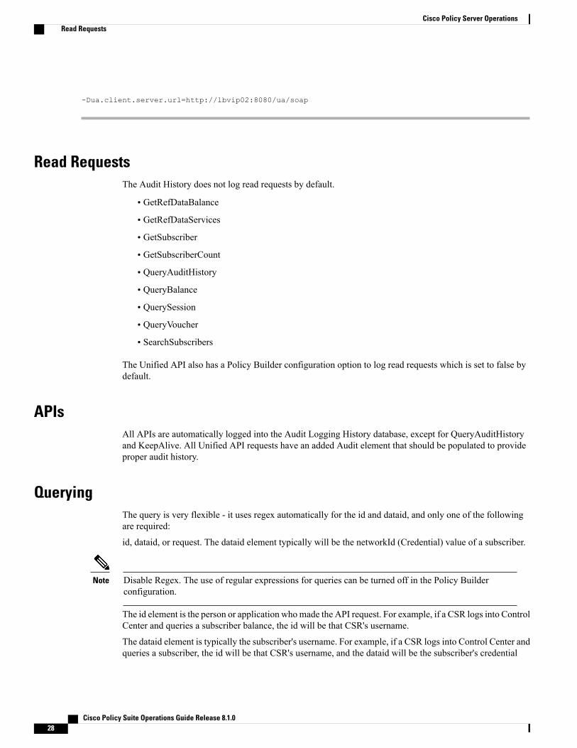
-Dua.client.server.url=http://lbvip02:8080/ua/soap
Read RequestsThe Audit History does not log read requests by default.
• GetRefDataBalance
• GetRefDataServices
• GetSubscriber
• GetSubscriberCount
• QueryAuditHistory
• QueryBalance
• QuerySession
• QueryVoucher
• SearchSubscribers
The Unified API also has a Policy Builder configuration option to log read requests which is set to false bydefault.
APIsAll APIs are automatically logged into the Audit Logging History database, except for QueryAuditHistoryand KeepAlive. All Unified API requests have an added Audit element that should be populated to provideproper audit history.
QueryingThe query is very flexible - it uses regex automatically for the id and dataid, and only one of the followingare required:
id, dataid, or request. The dataid element typically will be the networkId (Credential) value of a subscriber.
Disable Regex. The use of regular expressions for queries can be turned off in the Policy Builderconfiguration.
Note
The id element is the person or application whomade the API request. For example, if a CSR logs into ControlCenter and queries a subscriber balance, the id will be that CSR's username.
The dataid element is typically the subscriber's username. For example, if a CSR logs into Control Center andqueries a subscriber, the id will be that CSR's username, and the dataid will be the subscriber's credential
Cisco Policy Suite Operations Guide Release 8.1.028
Cisco Policy Server OperationsRead Requests

(networkId value). For queries, the dataid value is checked for spaces and then tokenized and each word isused as a search parameter. For example, “networkId1 networkId2” is interpreted as two values to check.The fromDate represents the date in the past from which to start the purge or query. If the date is null, the apistarts at the oldest entry in the history.
The toDate represents the date in the past to which the purge or query of data includes. If the date is null, theapi includes the most recent entry in the purge or query.
PurgingBy default, the Audit History database is capped at 1 GB. Mongo provides a mechanism to do this and thenthe oldest data is purged as new data is added to the repository. There is also a PurgeAuditHistory requestwhich can purge data from the repository. It uses the same search parameters as the QueryAuditHistory andtherefore is very flexible in how much or how little data is matched for the purge.
Regex Queries! Be very careful when purging records from the Audit History database. If a value is givenfor dataid, the server uses regex to match on the dataid value and therefore will match many more recordsthan expected. Use the QueryAuditHistory API to test the query.
Note
Purge HistoryEach purge request is logged after the purge operation completes. This ensures that if the entire repo isdestroyed, the purge action that destroyed the repo will be logged.
Control CenterThe Control Center version 2.0 automatically logs all requests.
PurgeAuditHistoryRequestThis API purges the Audit History. For more information, refer to Audit History, on page 26.
The query is very flexible - it uses regex automatically for the id and dataid, and only one of the followingare required: id, dataid, or request. The dataid element typically will be the networkId (Credential) value ofa subscriber.
The id element is the person or application whomade the API request. For example, if a CSR logs into ControlCenter and queries a subscriber balance, the id will be that CSR's username.
The dataid element is typically the subscriber's username. For example, if a CSR logs into Control Center andqueries a subscriber, the id will be that CSR's username, and the dataid will be the subscriber's credential(networkId value). For queries, the dataid value is checked for spaces and then tokenized and each word isused as a search parameter. For example, “networkId1 networkId2” is interpreted as two values to check.The fromDate represents the date in the past from which to start the purge or query. If the date is null, the apistarts at the oldest entry in the history.
Cisco Policy Suite Operations Guide Release 8.1.0 29
Cisco Policy Server OperationsPurging

The toDate represents the date in the past to which the purge or query of data includes. If the date is null, theapi includes the most recent entry in the purge or query.
Size-Capped Database
If the database is capped by size, then the purge request ignores the request key values and drops the entiredatabase due to restrictions of the database software.
Note
Schema<PurgeAuditHistoryRequest><key> AuditKeyType </key> [1]</PurgeAuditHistoryRequest>
Example<se:Envelope xmlns:se="http://schemas.xmlsoap.org/soap/envelope/"><se:Body><PurgeAuditHistoryRequest xmlns="http://broadhop.com/unifiedapi/soap/types"><key><id>username</id><dataid>subscriber</dataid><request>API Name</request><fromDate>2011-01-01T00:00:00Z</fromDate><toDate>2011-01-01T00:00:00Z</toDate>
</key></PurgeAuditHistoryRequest>
</se:Body></se:Envelope>
To purge all CreateSubscriberRequest:<se:Envelope xmlns:se="http://schemas.xmlsoap.org/soap/envelope/"><se:Body><PurgeAuditHistoryRequest xmlns="http://broadhop.com/unifiedapi/soap/types"><key><request>CreateSubscriberRequest</request>
</key></PurgeAuditHistoryRequest>
</se:Body></se:Envelope>
To purge all CreateSubscriberRequest by CSR:<se:Envelope xmlns:se="http://schemas.xmlsoap.org/soap/envelope/"><se:Body><PurgeAuditHistoryRequest xmlns="http://broadhop.com/unifiedapi/soap/types"><key><id>csrusername</id><request>CreateSubscriberRequest</request>
</key></PurgeAuditHistoryRequest>
</se:Body></se:Envelope>
To purge all actions by CSR for a given subscriber for a date range:<se:Envelope xmlns:se="http://schemas.xmlsoap.org/soap/envelope/"><se:Body><PurgeAuditHistoryRequest xmlns="http://broadhop.com/unifiedapi/soap/types"><key><id>csrusername</id><dataid>[email protected]</dataid><fromDate>2010-01-01T00:00:00Z</fromDate><toDate>2012-11-01T00:00:00Z</toDate>
</key></PurgeAuditHistoryRequest>
Cisco Policy Suite Operations Guide Release 8.1.030
Cisco Policy Server OperationsPurgeAuditHistoryRequest
</se:Body></se:Envelope>
QueryAuditHistoryRequestThis API queries the Audit History. For more information, refer to Audit History, on page 26.
The query is very flexible - it uses regex automatically for the id and dataid, and only one of the followingare required: id, dataid, or request. The dataid element typically will be the networkId (Credential) value ofa subscriber.
The id element is the person or application whomade the API request. For example, if a CSR logs into ControlCenter and queries a subscriber balance, the id will be that CSR's username.
The dataid element is typically the subscriber's username. For example, if a CSR logs into Control Center andqueries a subscriber, the id will be that CSR's username, and the dataid will be the subscriber's credential(networkId value). For queries, the dataid value is checked for spaces and then tokenized and each word isused as a search parameter. For example, "networkId1 networkId2" is interpreted as two values to check.
The fromDate represents the date in the past from which to start the purge or query. If the date is null, the apistarts at the oldest entry in the history.
The toDate represents the date in the past to which the purge or query of data includes. If the date is null, theapi includes the most recent entry in the purge or query.
Schema<QueryAuditHistoryRequest><key> AuditKeyType </key> [1]</QueryAuditHistoryRequest>
Example:<se:Envelope xmlns:se="http://schemas.xmlsoap.org/soap/envelope/"><se:Body><QueryAuditHistoryRequest xmlns="http://broadhop.com/unifiedapi/soap/types"><key><id>username</id><dataid>subscriber</dataid><request>API Name</request><fromDate>2011-01-01T00:00:00Z</fromDate><toDate>2011-01-01T00:00:00Z</toDate>
</key></QueryAuditHistoryRequest>
</se:Body></se:Envelope>
To find all CreateSubscriberRequest:<se:Envelope xmlns:se="http://schemas.xmlsoap.org/soap/envelope/"><se:Body><QueryAuditHistoryRequest xmlns="http://broadhop.com/unifiedapi/soap/types"><key><request>CreateSubscriberRequest</request>
</key></QueryAuditHistoryRequest>
</se:Body></se:Envelope>
To find all CreateSubscriberRequest by CSR:<se:Envelope xmlns:se="http://schemas.xmlsoap.org/soap/envelope/"><se:Body><QueryAuditHistoryRequest xmlns="http://broadhop.com/unifiedapi/soap/types"><key><id>csrusername</id><request>CreateSubscriberRequest</request>
Cisco Policy Suite Operations Guide Release 8.1.0 31
Cisco Policy Server OperationsQueryAuditHistoryRequest
</key></QueryAuditHistoryRequest>
</se:Body></se:Envelope>
To find all actions by CSR for a given subscriber for a date range:<se:Envelope xmlns:se="http://schemas.xmlsoap.org/soap/envelope/"><se:Body><QueryAuditHistoryRequest xmlns="http://broadhop.com/unifiedapi/soap/types"><key><id>csrusername</id><dataid>[email protected]</dataid><fromDate>2010-01-01T00:00:00Z</fromDate><toDate>2012-11-01T00:00:00Z</toDate>
</key></QueryAuditHistoryRequest>
</se:Body></se:Envelope>
Policy BuilderThe Policy Builder automatically logs all save operations (Publish and Save to Client) to the Audit Historydatabase and also to a log file.
• Policy Builder Publish submits an entry to the Audit Logging Server (goes to database).
• Policy Builder Save to Client Repository submits an entry to the Audit Logging Server (goes to database).
•Whenever a screen is saved locally (Save button) XML is generated and logged for that user in/var/log/broadhop/qns-pb.log.
Example log in qns-pb.log from Local Save in Policy Builder:2013-02-06 11:57:01,214 [UIThread [vt75cjqhk7v4noguyc9c7shp]] DEBUGc.b.c.r.BroadhopResourceSetAudit -Audit: Local file change made by: broadhop. Updated File:file:/var/broadhop/pb/workspace/tmp-ITC2/checkout/ConfiguredExtensionPoint-43730cd7-b238-4b29-a828-d9b447e5a64f-33851.xmi
XML Representation of changed screen:<?xml version="1.0" encoding="UTF-8"?><policy:ConfiguredExtensionPoint xmlns:policy="http://broadhop.com/policy"id="43730cd7-b238-4b29-a828-d9b447e5a64f-33851"><extensionPointhref="virtual:URI#_vxG4swK1Ed-M48DL9vicxQ"/>
<policieshref="Policy-default-_sY__4L_REeGCdakzuzzlAg.xmi#_sY__4L_REeGCdakzuzzlAg"/>
</policy:ConfiguredExtensionPoint>
Controlling Local Save output:
In the logback.xml file that controls Policy Builder logging, addcom.broadhop.client.resourceset.BroadhopResourceSetAudit as a category and set it to the desired level.
ReportingFor reporting purposes the following is the database structure in Mongo
{
"_id" : ObjectId("5097d75be4b0d5f7ab0d90fe"),
Cisco Policy Suite Operations Guide Release 8.1.032
Cisco Policy Server OperationsPolicy Builder

"_id_key" : "username",
"comment_key" : "comment",
"data_id_key" : [ "networkId11921" ],
"timestamp_key" : ISODate("2012-11-05T15:12:27.673Z"),
"request_key" : "DeleteQuotaRequest",
"data_key" :"<DeleteQuotaRequest><audit><id>username</id></audit><networkId><![CDATA[networkId11921]]></networkId><balanceCode>DATA</balanceCode><code>Recurring</code><hardDelete>false</hardDelete></DeleteQuotaRequest>"}
Table 2: Reporting Keys
DescriptionField
The database unique identifier._id
the username of person who performed the action. In the above example the CSRwho issued the debit request.
_id_key
Some description of the audit action.comment_key
The credential of the subscriber. It is a list so if the subscriber has multiplecredentials then they will all appear in this list. Please note that it is derived fromthe request data so for a CreateSubscriber request there may bemultiple credentialssent in the request then each will be saved in the data_id_key list. In theDebitRequest case only the one credential is listed because the request only hasthe single networkId field.
data_id_key
The time the request was logged If the timestamp value is null in the request thenthe Audit module automatically populates this value.
timestamp_key
The name of the request. This provides a way to search on type of API request.request_key
The actual request XML.data_key
Cisco Policy Suite Operations Guide Release 8.1.0 33
Cisco Policy Server OperationsReporting

Audit Configuration
Step 1 Click the Reference Data tab, and then click Systems > system name > Plugin Configurations.
Figure 10: Plugin Configurations Summary
Cisco Policy Suite Operations Guide Release 8.1.034
Cisco Policy Server OperationsAudit Configuration

Step 2 Click Audit Configuration in the right pane to open the Audit Configuration dialog box.
Figure 11: Audit Configuration dialog box
Cisco Policy Suite Operations Guide Release 8.1.0 35
Cisco Policy Server OperationsAudit Configuration

Step 3 Under Audit Configuration there are different panes: General Configuration, Queue Submission Configuration,Database Configuration, and Shard Configuration. An example configuration is provided in the following figures:
Figure 12: Queue Submission Configuration pane
Figure 13: Database Configuration pane
Figure 14: Shard Configuration pane
Cisco Policy Suite Operations Guide Release 8.1.036
Cisco Policy Server OperationsAudit Configuration

The following parameters are used to size and manage the internal queue that aids in the processing of Audit messages.
The application offloads message processing to a queue to speed up the response time from the API.
Table 3: Audit Configuration Parameters
DescriptionParameter
General Configuration
Select this check-box to activate capped collection function.Capped Collection
By default, the Audit History uses a 1 GB capped collection in Mongo Db.The capped collection automatically removes documents when the sizerestriction threshold is hit.
Configuration in Policy Builder is done in GB increments. It is possible toenter decimals, for example,9.5 will set the capped collection to 9.5 GB.
Capped Collection Size
Select this check-box if you want read requests to be logged.Log Read Requests
Select this check-box only if you want to include read requests to bedisplayed in query results.
Include Read Requests in Query Results
If you select this check-box, the use of regular expressions for queries isturned off in the Policy Builder configuration.
Disable Regex Search
This parameter limits the search results.Search Query Results Limit
Queue Submission Configuration
Total number of messages the queue can hold at any given time.Message Queue Size
The amount of time for the runnable to sleep between batch processing.The time is in milliseconds.
Message Queue Sleep
The number of messages to process in a given wake cycle.Message Queue Batch Size
The number of threads in the execution pool to handle message processing.Message Queue Pool Size
Database Configuration
Controls the write behavior of sessionMgr and for what errors exceptionsare raised. Default option is OneInstanceSafe.
Db Write Concern
Read preference describes how sessionMgr clients route read operations tomembers of a replica set. The recommended option is typically SecondaryPreferred.
http://docs.mongodb.org/manual/core/read-preference/
Db Read Preference
Cisco Policy Suite Operations Guide Release 8.1.0 37
Cisco Policy Server OperationsAudit Configuration

DescriptionParameter
This parameter is used to enter the amount of time to wait before startingfailover database handling. The time is in milliseconds.
Failover Sla Ms
This option specifies a time limit, in milliseconds, for the write concern.This parameter is applicable only if you select TwoInstanceSafe in DbWriteConcern.
This parameter causes write operations to return with an error after thespecified limit, even if the required write concern eventually succeeds.When these write operations return, MongoDB does not undo successfuldata modifications performed before the write concern exceeded thereplication wait time limit. This time is in milliseconds.
Max Replication Wait time Ms
Shard Configuration
Enter the primary IP address for sharding.Primary Ip Address
Enter the secondary IP address for sharding.Secondary Ip Address
Enter the port number.Port
According to your network requirements, configure the parameters in Audit Configuration and save the configuration.
Pre-configuration in AuditIn the /usr/share/doc/audit-version/ directory, the audit package provides a set of pre-configuredrules files according to various following certification standards:
• nispom.rules: Audit rule configuration that meets the requirements specified in Chapter 8 of the NationalIndustrial Security Program Operating Manual.
• capp.rules: Audit rule configuration that meets the requirements set by Controlled Access ProtectionProfile (CAPP), which is a part of the Common Criteria certification.
• lspp.rules: Audit rule configuration that meets the requirements set by Labeled Security Protection Profile(LSPP), which is a part of the Common Criteria certification.
• stig.rules: Audit rule configuration that meets the requirements set by Security Technical ImplementationGuides (STIG).
To use these configuration files, create a backup of your original /etc/audit/audit.rules file andcopy the configuration file of your choice over the /etc/audit/audit.rules file:cp /etc/audit/audit.rules /etc/audit/audit.rules_backupcp /usr/share/doc/audit-version/stig.rules /etc/audit/audit.rules
Cisco Policy Suite Operations Guide Release 8.1.038
Cisco Policy Server OperationsPre-configuration in Audit

Policy Tracing and Execution AnalyzerCisco Policy Server comes with a set of utilities to actively monitor and trace policy execution. These utilitiesinteract with the core policy server and the mongo database to trigger and store traces for specific conditions.This section covers the following topics:
• Architecture, on page 39
• Administering Policy Traces, on page 39
• Administer the Policy Trace Database, on page 41
• Enabling Traces in mongo, on page 42
ArchitectureThe policy tracing and execution analyzer is 3-tier architecture:
• Tier 1— command line utilities to manage the policy trace generation and extract policy traces.
• Tier 2— policy server creation of policy traces using triggers defined in Tier 1
• Tier 3— storage of the policy traces in a MongoDB database
Administering Policy TracesAll commands are located on the Control Center virtual machinewithin/var/qps/bin/control directory.There are two main scripts which can be used for tracing: trace_ids.sh and trace.sh. The trace_ids.sh scriptmaintains all rules for activating and deactivating traces within the system. The trace.sh script allows for thereal time or historical retrieval of traces.
Managing Trace Rules via trace_ids.shRunning trace_ids.sh with no arguments produces a help text describing the capabilities of the script.
[root@pcrfclient01 control]# trace_ids.sh
Usage:/var/qps/bin/control/trace_ids.sh -i <specific id> -d sessionmgr01:27719/policy_trace/var/qps/bin/control/trace_ids.sh -r <specific id> -d sessionmgr01:27719/policy_trace/var/qps/bin/control/trace_ids.sh -x -d sessionmgr01:27719/policy_trace/var/qps/bin/control/trace_ids.sh -l -d sessionmgr01:27719/policy_trace
This script starts a selective trace and outputs it to standard out.
Step 1 Add Specific Audit Id Tracing:/var/qps/bin/control/trace_ids.sh -i <specific id>
Step 2 Remove Trace for Specific Audit Id:/var/qps/bin/control/trace_ids.sh -r <specific id>
Cisco Policy Suite Operations Guide Release 8.1.0 39
Cisco Policy Server OperationsPolicy Tracing and Execution Analyzer

Step 3 Remove Trace for All Ids:/var/qps/bin/control/trace_ids.sh -x
Step 4 List All Ids under Trace:/var/qps/bin/control/trace_ids.sh -l
All commands must specify the “-d” argument for the primary database hosting the policy traces. The format of thedatabase format <db ip or fqdn>:<db port>/policy_trace.
Adding a specific audit id for tracing requires running the command with the -i argument and passing in a specific id.The policy server matches the incoming session with the ID provided and compares this against the following networksession attributes:
• Credential ID
• Framed IP v6 Prefix
• IMSI
• MAC Address
• MSISDN
• User ID
If an exact match is found then the transaction are traced. Spaces and special characters are not supported in the auditids.
• Removing a specific audit id from active tracing requires specifying the -r argument with id to remove.
• Removing all ids requires sending in the -x argument and this will remove all ids from the database.
• Listing all ids requires sending in the -l argument.
Situations where traces are generated automatically
The following criteria cause the system to generate a trace regardless of whether the id is present in the tracedatabase or not:
• If there is an AVP with the code: audit_id, audit-id, auditid. In this case, the traces are stored in thedatabase with the value of the AVP.
• If there is a subscriber attribute (USuM AVP) with a code of audit-policy and a value of “true”. In thiscase, the traces are stored using the credentials stored for the subscriber.
• If an error is triggered internally.
An error is defined as an internal processing error (e.g. database failure or other failure)and is not a failure message code.
Note
Cisco Policy Suite Operations Guide Release 8.1.040
Cisco Policy Server OperationsAdministering Policy Traces

Outputting Trace results via trace.sh
Running trace.sh with no arguments produces a help text describing the capabilities of the script:
[root@pcrfclient01 control]# trace.sh
Usage:/var/qps/bin/control/trace.sh -i <specific id> -d sessionmgr01:27719/policy_trace/var/qps/bin/control/trace.sh -x <specific id> -d sessionmgr01:27719/policy_trace/var/qps/bin/control/trace.sh -a -d sessionmgr01:27719/policy_trace/var/qps/bin/control/trace.sh -e -d sessionmgr01:27719/policy_trace
This script starts a selective trace and outputs it to standard out.
Step 1 Specific Audit Id tracing:/var/qps/bin/control/trace.sh -i <specific id>
Step 2 Dump All Traces for Specific Audit Id:/var/qps/bin/control/trace.sh -x <specific id>
Step 3 Trace All:/var/qps/bin/control/trace.sh -a
Step 4 Trace All Errors:/var/qps/bin/control/trace.sh -e
All commands must specify the -d argument for the primary database hosting the policy traces. The format of the databaseformat <db ip or fqdn>:<db port>/policy_trace. The output format is similar to the current engine logformat.
• Specifying the -i argument for a specific ID causes a real time policy trace to be generated while the script isrunning. Users can redirect this to a specific output file using standard Linux commands.
• Specifying the -a argument causes all traces to output in real time policy trace while the script is running. Userscan redirect this to a specific output file using standard Linux commands.
• Specifying the -e argument causes all traces triggered by an error to output in real time policy trace while the scriptis running. Users can redirect this to a specific output file using standard Linux commands.
• Specifying the -x argument with a specific dumps all historical traces for a given id. Users can redirect this to aspecific output file using standard Linux commands.
Administer the Policy Trace DatabaseThe default location of the policy trace database is the administrative database and can be optionally specifiedin the trace db fields. These fields are defined at the cluster level in the system configurations.
Make sure to run all trace utility scripts from /var/qps/bin/control directory only.Note
Cisco Policy Suite Operations Guide Release 8.1.0 41
Cisco Policy Server OperationsAdminister the Policy Trace Database

Enabling Traces in mongo
Step 1 Log in to the Policy Builder.Step 2 For cluster, select the Trace Db check box to open the trace pane.Step 3 Specify the db name and port number where the traces must be written. By default, traces are written in admin DB. An
example is shown below.
Figure 15: Admin Db Configuration
TACACS+This section covers the following topics:
• Overview, on page 43
Cisco Policy Suite Operations Guide Release 8.1.042
Cisco Policy Server OperationsEnabling Traces in mongo
• TACACS+ Service Requirements, on page 43
• Caching of TACACS+ Users, on page 44
OverviewCisco Policy Suite (CPS) is built around a distributed system that runs on a large number of virtualized nodes.Previous versions of the CPS software allowed operators to add custom accounts to each of these virtualmachines (VM), but management of these disparate systems introduced a large amount of administrativeoverhead.
CPS has been designed to leverage the Terminal Access Controller Access Control System Plus (TACACS+)to facilitate centralizedmanagement of users. Leveraging TACACS+, the system is able to provide system-wideauthentication, authorization, and accounting (AAA) for the CPS system.
Further the system allows users to gain different entitlements based on user role. These can be centrallymanaged based on the attribute-value pairs (AVP) returned on TACACS+ authorization queries.
TACACS+ Service Requirementsattribute-value pairs (AVP) that must be associated with the user on the ACS server used by the deployment.User records on Unix-like systems need to have a valid “passwd” record for the system to operate correctly.Several of these fields can be inferred during the time of user authentication, but the remaining fields mustbe provided by the ACS server.
A standard “passwd” entry on a Unix-like system takes the following form:
<username>:<password>:<uid>:<gid>:<gecos>:<home>:<shell>
When authenticating the user via TACACS+, the software can assume values for the username, password,and gecos fields, but the others must be provided by the ACS server. To facilitate this need, the system dependson the ACS server provided these AVP when responding to a TACACS+ Authorization query for a given'username':
• uidA unique integer value greater than or equal to 501 that serves as the numeric user identifier for theTACACS+ authenticated user on the VM nodes. It is outside the scope of the CPS software to ensureuniqueness of these values.
• gidThe group identifier of the TACACS+ authenticated user on the VM nodes. This value should reflectthe role assigned to a given user, based on the following values:
◦gid=501 (qns-su)
This group identifier should be used for users that are entitled to attain super-user (or 'root') accesson the CPS VM nodes.
◦gid=504 (qns-admin)
This group identifier should be used for users that are entitled to perform administrativemaintenanceon the CPS VM nodes.
Cisco Policy Suite Operations Guide Release 8.1.0 43
Cisco Policy Server OperationsOverview

For stopping/starting the qns process on node, the qns-admin user should use monit:Note
For example,sudo monit stop qns-1sudo monit start qns-1
◦gid=505 (qns-ro)
This group identifier should be used for users that are entitled to read-only access to the CPS VMnodes.
• homeThe user's home directory on the CPS VM nodes. To enable simpler management of these systems, theusers should be configured with a pre-deployed shared home directory based on the role they are assignedwith the gid.
◦home=/home/qns-su should be used for users in the qns-su group (gid=501)
◦home=/home/qns-admin should be used for users in the qnsadmin group (gid=504)
◦home=/home/qns-ro should be used for users in the qns-ro group (gid=505)
• shellThe system-level login shell of the user. This can be any of the installed shells on the CPS VM nodes,which can be determined by reviewing the contents of /etc/shells on one of the CPS VM nodes.Typically, this set of shells is available in a CPS deployment:
◦/bin/sh
◦/bin/bash
◦/sbin/nologin
◦/bin/dash
◦/usr/bin/sudosh
The /usr/bin/sudosh shell can be used to audit user's activity on the system.
Caching of TACACS+ UsersThe user environment of the Linux-based VMs needs to be able to lookup a user's passwd entry via differentcolumns in that record at different times. The TACACS+ NSS module provided as part of the CPS solutionhowever is only able to query the Access Control Server (ACS) for this data using the username. For thisreason the system relies upon the Name Service Cache Daemon (NSCD) to provide this facility locally aftera user has been authorized to use a service of the ACS server.
More details on the operations of NSCD can be found by referring to online help for the software (nscd --help)or in its man page (nscd(8)). Within the CPS solution it provides a capability for the system to lookup a user'spasswd entry via their uid as well as by their username.
Cisco Policy Suite Operations Guide Release 8.1.044
Cisco Policy Server OperationsCaching of TACACS+ Users

To avoid cache coherence issues with the data provided by the ACS server the NSCD package has a mechanismfor expiring cached information.
The default NSCD package configuration on the CPS VM nodes has the following characteristics:
• Valid responses from the ACS server are cached for 600 seconds (10 minutes)
• Invalid responses from the ACS server (user unknown) are cached for 20 seconds
• Cached valid responses are reloaded from the ACS server 5 times before the entry is completely removedfrom the running set -- approximately 3000 seconds (50 minutes)
• The cache are persisted locally so it survives restart of the NSCD process or the server
It is possible for an operator to explicitly expire the cache from the command line. To do so the administratorneed to get the shell access to the target VM and execute the following command as a root user:
# nscd -i passwd
The above command will invalidate all entries in the passwd cache and force the VM to consult with the ACSserver for future queries.
Theremay be some unexpected behaviors of the user environment for TACACS+ authenticated users connectedto the system when their cache entries are removed from NSCD. This can be corrected by the user by loggingout of the system and logging back into it or by issuing the following command, which forces the system toquery the ACS server:
# id -a “$USER”
Porting All-In-One Policy Builder Configuration to HAThis section describes how to port the Policy Builder configuration from an All-In-One (AIO) environmentto a High Availability (HA) environment.
Prerequisites• All the VMs were created using the 7.x deployment process.
• This procedure assumes the datastore that will be used to have the virtual disk has sufficient space toadd the virtual disk.
• This procedure assumes the datastore has been mounted to the VMware ESX server, regardless of thebackend NAS device (SAN or iSCSI, etc).
Porting the Policy Builder ConfigurationPolicy Builder configuration can be utilized between environments, however, the configuration for Systemsand Policy Enforcement Points is environment-specific and should not be moved from one environment toanother.
The following instructions will not overwrite the configuration specific to the environment. Please note thatas the Systems tab and Policy Enforcement Points data is not moved, the HA system should have these thingsconfigured and running properly (as stated above).
Cisco Policy Suite Operations Guide Release 8.1.0 45
Cisco Policy Server OperationsPorting All-In-One Policy Builder Configuration to HA

The following steps describe the process to port a configuration from an AIO environment to an HAenvironment.
Step 1 If the HA environment is currently in use, ensure that SVN backups are up to date.Step 2 Find the URL that Policy Builder is using to load the configuration that you want to use. You can find this by clicking
Edit on the initial page in Policy Builder.The URL is listed in the URL field. For the purpose of these instructions, the following URL will be used for exportingthe configuration from the AIO environment and importing the configuration to the HA environment:
http://pcrfclient01/repos/configuration
Figure 16: Repository configuration
Step 3 On the AIO, export the Policy Builder configuration by entering the following commands:cd /var/tmpsvn export http://pcrfclient01/repos/configuration aio_configuration
This creates a directory /var/tmp/aio_configuration.
Step 4 Remove the system configuration by entering the following commands:cd aio_configurationrm -f System* *Configuration* DiameterStack* VoucherSettings* Cluster* Instance*
Step 5 Move the /var/tmp/aio_configuration directory to /var/tmp on your ClusterManager (using scp, zip, etc.).Step 6 SSH into the pcrfclient01.
Cisco Policy Suite Operations Guide Release 8.1.046
Cisco Policy Server OperationsPorting the Policy Builder Configuration
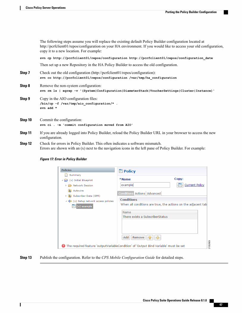
The following steps assume you will replace the existing default Policy Builder configuration located athttp://pcrfclient01/repos/configuration on your HA environment. If you would like to access your old configuration,copy it to a new location. For example:
svn cp http://pcrfclient01/repos/configuration http://pcrfclient01/repos/configuration_date
Then set up a new Repository in the HA Policy Builder to access the old configuration.
Step 7 Check out the old configuration (http://pcrfclient01/repos/configuration):svn co http://pcrfclient01/repos/configuration /var/tmp/ha_configuration
Step 8 Remove the non-system configuration:svn rm ls | egrep -v '(System|Configuration|DiameterStack|VoucherSettings|Cluster|Instance)'
Step 9 Copy in the AIO configuration files:/bin/cp -f /var/tmp/aio_configuration/* .svn add *
Step 10 Commit the configuration:svn ci . -m 'commit configuration moved from AIO'
Step 11 If you are already logged into Policy Builder, reload the Policy Builder URL in your browser to access the newconfiguration.
Step 12 Check for errors in Policy Builder. This often indicates a software mismatch.Errors are shown with an (x) next to the navigation icons in the left pane of Policy Builder. For example:
Figure 17: Error in Policy Builder
Step 13 Publish the configuration. Refer to the CPS Mobile Configuration Guide for detailed steps.
Cisco Policy Suite Operations Guide Release 8.1.0 47
Cisco Policy Server OperationsPorting the Policy Builder Configuration

Cisco Policy Suite Operations Guide Release 8.1.048
Cisco Policy Server OperationsPorting the Policy Builder Configuration

C H A P T E R 2Graphite and Grafana
• Introduction, page 49
• Configure Grafana Users, page 51
• Connect to Grafana, page 52
• Grafana Administrative User, page 53
• Configure Grafana for First Use, page 54
• Manual Dashboard Configuration using Grafana, page 57
• Configure Useful Dashboard Panels, page 63
• Configure Garbage Collector KPIs, page 65
• Export and Import Dashboards, page 68
• Export Graph Data to CSV, page 70
IntroductionCPS system and application statistics and Key Performance Indicators (KPI) are collected by the system andcan be displayed using a browser-based graphical metrics tool. This chapter provides a high level overviewof the tools CPS uses to collect and display these statistics.
The list of statistics available in CPS is consolidated in an Excel spreadsheet. After CPS is installed, thisspreadsheet can be found in the following location on the Cluster Manager VM:
/var/qps/install/current/scripts/documents/QPS_statistics.xlsx
GraphiteCollectd clients running on all CPS Virtual Machines (such as qns, lb, and sessionmgr) push data to theCollectd master on the pcrfclient01. The Collectd master node in turn forwards the collected data to theGraphite database on the pcrfclient01.
The Graphite database stores system related statistics such as CPU usage, memory usage, and Ethernet interfacestatistics, as well as application message counters such as Gx, Gy, and Sp message counters.
Cisco Policy Suite Operations Guide Release 8.1.0 49

Each pcrfclient (01 and 02) collects and stores these bulk statistics independently.
As a best practice, always use the bulk statistics collected from pcrfclient01. Pcrfclient02 can be used as abackup in the event of failure of pcrfclient01.
In the event that pcrfclient01 becomes unavailable, statistics will still be gathered on pcrfclient02. Statisticsdata is not synchronized between pcrfclient01 and pcrfclient02, so a gap would exists in the collected statisticswhile pcrfclient01 is down.
It is normal to have slight differences between the data on pcrfclient01 and pcrfclient02. For example,pcrfclient01 will generate a file at time t and pcrfclient02 will generate a file at time t +/- clock driftbetween the two machines.
Note
Additional Graphite DocumentationTo learn more about Grafana, refer to: http://graphite.readthedocs.org/en/latest/
For a list of all functions that can be used to transform, combine and perform computations on data stored inGraphite, refer to: http://graphite.readthedocs.org/en/latest/functions.html
GrafanaGrafana is a third-party metrics dashboard and graph editor provided with CPS 7.0 and higher.
Grafana provides a graphical or text-based representation of statistics and counters collected in the Graphitedatabase.
Additional Grafana DocumentationThis chapter provides information about the CPS implementation of Grafana. For more information aboutGrafana, or access the general Grafana documentation, refer to: http://docs.grafana.org
Cisco Policy Suite Operations Guide Release 8.1.050
Graphite and GrafanaGrafana

Configure Grafana UsersIn CPS 7.0.5 and higher releases, users must be authenticated to access Grafana. No default users are provided.In order to access Grafana, you must add at least one user as described in the sections below.
• The following steps describe how to add and delete users who are allowed view-only access of Grafana.In order to create or modify dashboards, refer to Grafana Administrative User, page 52.
• After adding or deleting a Grafana user, manually copy the /var/broadhop/.htpasswd file from thepcrfclient01 VM to the pcrfclient02 VM.
• There is no method to change the password for a Grafana user; you can only add and delete users. Thechange_passwd.sh script cannot be used to change the password for Grafana users.
Log on to the pcrfclient01 VM to perform any of the following commands.
Add a User
Step 1 Run the following command on the pcrfclient01 VM:/usr/bin/htpasswd -cs /var/broadhop/.htpasswd user1
Step 2 When prompted for a password, enter and re-enter the password.This step creates a password file and forces SHA encryption of the password.
Add Another User
Step 1 Run the following command on the pcrfclient01 VM:/usr/bin/htpasswd /var/broadhop/.htpasswd user2
Step 2 When prompted for a password, enter and re-enter the password.
Delete a User
Run the following command on the pcrfclient01 VM:/usr/bin/htpasswd -D /var/broadhop/.htpasswd user2
Cisco Policy Suite Operations Guide Release 8.1.0 51
Graphite and GrafanaConfigure Grafana Users

Connect to GrafanaUse the following URL to access Grafana.
• HA: https://<lbvip01>:9443/grafana
• All in One: http://<ip>/grafana
When prompted, enter the username and password of a user you created in Configure Grafana Users, on page51.
Figure 18: Grafana Home Screen
Cisco Policy Suite Operations Guide Release 8.1.052
Graphite and GrafanaConnect to Grafana

Grafana Administrative User
Log in as Grafana Admin UserTo create or modify dashboards in Grafana, you must log in as the Grafana administrative user.
Step 1 Click the Grafana logo in the upper left corner of your screen.
Figure 19: Grafana Logo
Step 2 Click Sign In.Step 3 Enter the administrative username and password: admin/admin
Cisco Policy Suite Operations Guide Release 8.1.0 53
Graphite and GrafanaGrafana Administrative User

Change Grafana Admin User Credentials
Step 1 Log in as the administrative user (admin/admin).Step 2 Click the Grafana logo, then click Grafana admin.Step 3 Click Global Users.Step 4 Click Edit.
Figure 20: Changing Grafana Admin User Credentials
Configure Grafana for First UseAfter an initial installation or after upgrading an existing CPS deployment which used Grafana, you mustperform the steps in the following sections to validate the existing data sources.
Validate and Finalize Grafana Data SourcesBy default, Grafana is configured to have two Data Sources, as shown below. Unless instructed by a Ciscorepresentative, you do not need to modify these Data Sources.
After CPS is installed or upgraded, perform the following steps to verify the integrity of the data sources.
Step 1 Log in as the Grafana Administrative User.Step 2 Click Data Sources.
If the data sources screen appears as shown below, proceed to Migrate Existing Grafana Dashboards.
If there are errors or the screen does not appear as shown, refer to Repair Data Sources.
Cisco Policy Suite Operations Guide Release 8.1.054
Graphite and GrafanaChange Grafana Admin User Credentials

Step 3 To finalize these data source connections, click Edit, then click Save. Perform these actions separately for each datasource.
Repair Data SourcesIf a data source connection is missing or becomes corrupted, use the following steps to recreate the datasources.
Step 1 Navigate to the Data Sources screen as described in Validate and Finalize Grafana Data Sources.Step 2 Delete any existing corrupted data sources by clicking the red X.Step 3 Click Add new at the top of the screen, then enter the following information:
Name: Graphite Via UI
Default: Select this checkbox.
Type: Graphite (default)
URL: http://127.0.0.1/graphite
Access: proxy (default)
Basic Auth: leave unchecked
Step 4 Click Add.Step 5 Click Add new to create a second data source, then enter the following information.
Name: Elasticsearch Via UI
Default: Leave unchecked.
Type: Elasticsearch (via pulldown)
URL: http://127.0.0.1/elasticsearch
Access: proxy (default)
Cisco Policy Suite Operations Guide Release 8.1.0 55
Graphite and GrafanaRepair Data Sources

Basic Auth: leave unchecked
Index name: grafana-dash
Pattern: No pattern (default)
Time field name: @timestamp (default)
Step 6 Click Add.Step 7 Click Save. The repair steps are complete.
Migrate Existing Grafana DashboardsDuring an upgrade of CPS (and Grafana), saved dashboard templates remain intact.
After upgrading an existing CPS deployment, you must manually migrate any existing Grafana dashboards.
Step 1 Sign in as the Grafana Administrative User. For more information, refer to Grafana Administrative User.Step 2 Click Home at the top of the Grafana window and then click Import as shown below:
Cisco Policy Suite Operations Guide Release 8.1.056
Graphite and GrafanaMigrate Existing Grafana Dashboards

Step 3 In the Migrate dashboards section, verify that Elasticsearch Def (Elasticsearch Default via API) is listed, then clickImport.
Step 4 All existing dashboards are imported and should now be available.
Manual Dashboard Configuration using GrafanaGrafana enables you to create custom dashboards which provide graphical representations of data by fetchinginformation from the Graphite database. Each dashboard is made up of panels spread across the screen inrows.
CPS includes a series of preconfigured dashboard templates. To use these dashboards, refer to UpdatingImported Templates.
Note
To create a new dashboard manually, perform the following steps:
1 Sign in as a Grafana Administrative user. For more information, refer to Grafana Administrative User.2 Click Home at the top of the Grafana window and select New as shown below:
Cisco Policy Suite Operations Guide Release 8.1.0 57
Graphite and GrafanaManual Dashboard Configuration using Grafana

A blank dashboard is created, as shown:
3 At the top of the screen, click the gear icon, then click Settings, as shown:
Cisco Policy Suite Operations Guide Release 8.1.058
Graphite and GrafanaManual Dashboard Configuration using Grafana
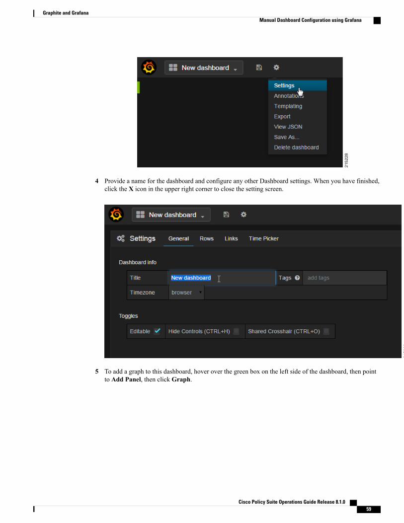
4 Provide a name for the dashboard and configure any other Dashboard settings. When you have finished,click the X icon in the upper right corner to close the setting screen.
5 To add a graph to this dashboard, hover over the green box on the left side of the dashboard, then pointto Add Panel, then click Graph.
Cisco Policy Suite Operations Guide Release 8.1.0 59
Graphite and GrafanaManual Dashboard Configuration using Grafana
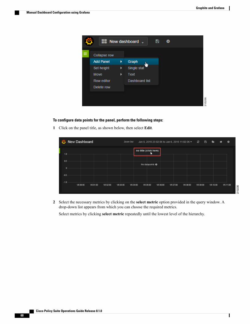
To configure data points for the panel, perform the following steps:
1 Click on the panel title, as shown below, then select Edit.
2 Select the necessary metrics by clicking on the select metric option provided in the query window. Adrop-down list appears from which you can choose the required metrics.
Select metrics by clicking select metric repeatedly until the lowest level of the hierarchy.
Cisco Policy Suite Operations Guide Release 8.1.060
Graphite and GrafanaManual Dashboard Configuration using Grafana

Clicking the ‘*’ option in the drop-down list, selects all the available metrics.Note
3 Click the ‘+’ tab to add aggregation functions for the selected metrics. the monitoring graph is displayedas shown below:
Cisco Policy Suite Operations Guide Release 8.1.0 61
Graphite and GrafanaManual Dashboard Configuration using Grafana

4 The x-axis and y-axis values can be configured in the Axes & Grid tab.
5 Click the disk icon (Save dashboard) at the top of the screen, as shown in the following image.
Your changes to this dashboard will be lost if you do not click the Save icon.Note
Graphical representation of application-messages such as - CCR, CCA, Gx, Gy, Ldap, Rx messages andso on, can be configured in the dashboard panel by using the queries shown in the below figure.
Cisco Policy Suite Operations Guide Release 8.1.062
Graphite and GrafanaManual Dashboard Configuration using Grafana

Configure Useful Dashboard PanelsThe following section describes the configuration of several useful dashboard panels that can be used whileprocessing Application Messages. Configure the dashboard panel as shown in the screens below.
Total Error:
This dashboard panel lists the errors found during the processing of ApplicationMessages. To configure TotalError dashboard panel, create a panel with name 'Total Error' and configure its query as shown:
Total Delay:
This dashboard panel displays the total delay in processing various Application Messages. To configure TotalDelay dashboard panel, create a panel with name Total Delay and configure its query as shown:
Cisco Policy Suite Operations Guide Release 8.1.0 63
Graphite and GrafanaConfigure Useful Dashboard Panels

Total TPS:
This panel displays the total TPS of CPS system. Total TPS count includes all Gx, Gy, Rx, Sy, Ldap and soon. The panel can be configured as shown below:
Updating Imported TemplatesSome of the preconfigured templates (such as diameter statistics panels) have matrices configured which arespecific to a particular set of diameter realms. These panels need to be reconfigured to match customer specificdiameter realms.
For example, the Gx PGW panel in the Diameter Statistics dashboard does not fetch the stats and displaysthe message “No Datapoints”. The probable reasons could be:
Cisco Policy Suite Operations Guide Release 8.1.064
Graphite and GrafanaUpdating Imported Templates

• Matrices used in query uses matrices specific to particular diameter realmwhich is different on customersetup.
• No application call of such type has ever landed on lbs of CPS (no diameter call from PGW has everlanded on lb after the Graphite-Grafana setup).
Configure Garbage Collector KPIsThe following sections describe the steps to configure Garbage Collector (GC) KPIs in Grafana:
• Backend changes: Changes in the collectd configuration so that GC related KPIs will be collected bycollectd and stored in graphite DB.
• Frontend changes: Changes in Grafana GUI for configuring metrics for GC graph.
Backend ChangesCheck if the following changes are already present in jmxplugin.conf file. If already configured then skip thissection and move to for configuring the Grafana dashboard.
1 Edit /etc/puppet/modules/qps/templates/collectd_worker/collectd.d/jmxplugin.conf on the ClusterManagerVM as described in the following steps.
2 Verify that the JMX plugin is enabled. The following lines must be present in the jmxplugin.conf file.JVMARG has path for jmx jar
JVMARG
-Djava.class.path=/usr/share/collectd/java/collectd-api.jar/usr/share/collectd/java/generic-jmx.jar
And GenericJMX plugin is loaded
LoadPlugin org.collectd.java.GenericJMX
3 Add an Mbean entry for garbage collector mbean in GenericJMX plugin so that statistics from this mbeanwill be collected
# Garbage collector information<MBean "garbage_collector">
ObjectName "java.lang:type=GarbageCollector,*"InstancePrefix "gc-"InstanceFrom "name"
<Value>Type "invocations"#InstancePrefix ""#InstanceFrom ""Table falseAttribute "CollectionCount"
</Value><Value>
Type "total_time_in_ms"InstancePrefix "collection_time"#InstanceFrom ""Table falseAttribute "CollectionTime"
</Value></MBean>
4 For every “Connection” block in jmxplugin.conf file add the entry for garbage collector mbean.
Cisco Policy Suite Operations Guide Release 8.1.0 65
Graphite and GrafanaConfigure Garbage Collector KPIs

For example<Connection>InstancePrefix "node1."
ServiceURL "service:jmx:rmi:///jndi/rmi://localhost:9053/jmxrmi"Collect "garbage_collector"Collect "java-memory"Collect "thread"Collect "classes"Collect "qns-counters"Collect "qns-actions"Collect "qns-messages"</Connection>]
5 Save the changes to the jmxplugin.conf file then synchronize the changes to all CPS VMs
a Go to the /var/qps/install/current/scripts/build/ directory on the Cluster Manager and execute thefollowing script:
./build_puppet.sh
b Go to the /var/qps/install/current/scripts/upgrade/ directory on the Cluster Manager and execute thefollowing command:
./reinit.sh
c Restart the collectd service on all VMs by running the following command on each VM in the CPScluster:
service collectd restart
Frontend ChangesThe frontend changes must be done in Grafana GUI.
1 Create a new Grafana dashboard. For more information refer to Manual Dashboard Configuration UsingGrafana.
2 In the Metrics tab of the new dashboard configure queries for GC related KPIs.The query needs to be configured in the following format:
cisco.quantum.qps.<hostname>.node*. gc*.total_time_in_ms-collection_time
cisco.quantum.qps.<hostname>.node*.gc*.invocations
where <host-name> is regular expression for the name of hosts from which KPI needs to be reported.
If this is a CPS All in One (AIO) deployment the host-name is “lab”.If this is a High Availability (HA) CPS deployment KPIs need to be reported from all QNS VMs.
Assuming the QNS VMs have “qns” in their hostname then a regular expression would be *qns*. Thiswould report data for all VMs which have a hostname containing “qns” (qns01 qns02 etc.).
Cisco Policy Suite Operations Guide Release 8.1.066
Graphite and GrafanaFrontend Changes

AIO Setup
Figure 21: On AIO Setup
On HA Setup
Figure 22: On HA Setup
An example statistics graph is shown below
Figure 23: Example Graph
3 Save the dashboard by clicking on Save icon.
Cisco Policy Suite Operations Guide Release 8.1.0 67
Graphite and GrafanaFrontend Changes
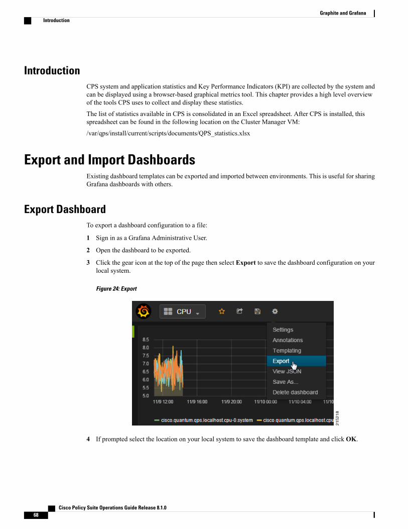
IntroductionCPS system and application statistics and Key Performance Indicators (KPI) are collected by the system andcan be displayed using a browser-based graphical metrics tool. This chapter provides a high level overviewof the tools CPS uses to collect and display these statistics.
The list of statistics available in CPS is consolidated in an Excel spreadsheet. After CPS is installed, thisspreadsheet can be found in the following location on the Cluster Manager VM:
/var/qps/install/current/scripts/documents/QPS_statistics.xlsx
Export and Import DashboardsExisting dashboard templates can be exported and imported between environments. This is useful for sharingGrafana dashboards with others.
Export DashboardTo export a dashboard configuration to a file:
1 Sign in as a Grafana Administrative User.
2 Open the dashboard to be exported.
3 Click the gear icon at the top of the page then select Export to save the dashboard configuration on yourlocal system.
Figure 24: Export
4 If prompted select the location on your local system to save the dashboard template and click OK.
Cisco Policy Suite Operations Guide Release 8.1.068
Graphite and GrafanaIntroduction

Import DashboardTo import a dashboard from a file:
1 Sign in as a Grafana Administrative User.2 Click Home at the top of the Grafana window and then click Import as shown below.
Figure 25: Import
Cisco Policy Suite Operations Guide Release 8.1.0 69
Graphite and GrafanaImport Dashboard

3 Click Choose File.
Figure 26: Choose File
4 Select the file on your local system to save the dashboard template and click Open.5 After the dashboard is loaded click the disk icon (Save dashboard) at the top of the screen to save the
dashboard.
Your changes to this dashboard will be lost if you do not save the dashboard.Note
Export Graph Data to CSVTo export the data in a graph panel to a CSV file
1 Click the title of the graph as shown below to open the graph controls.
Figure 27: Title
Cisco Policy Suite Operations Guide Release 8.1.070
Graphite and GrafanaExport Graph Data to CSV

2 Click the rows button to open another menu.
Figure 28: Rows
3 Click Export CSV.
Figure 29: Export
4 A grafana_data_export.csv file is downloaded by your browser.
Cisco Policy Suite Operations Guide Release 8.1.0 71
Graphite and GrafanaExport Graph Data to CSV

Cisco Policy Suite Operations Guide Release 8.1.072
Graphite and GrafanaExport Graph Data to CSV
C H A P T E R 3Custom Reference Data REST API
• Introduction, page 73
• Limitations, page 73
• Setup Requirements, page 74
• Architecture, page 79
• API Endpoints and Examples, page 80
IntroductionThe Custom Reference Data (CRD) APIs exists to allow query, creation, deletion, and update of CRD tabledata without the need to utilize the Control Center application. The CRD APIs are available via a RESTinterface. The specific APIs are Query, Create, Update, and Delete.
LimitationsThese APIs allow maintenance of the actual data rows in the table. They do not allow the creation of newtables or the addition of new columns. Table creation and changes to the table structure must be completedvia the Policy Builder application.
Table names must be all in lowercase alphanumeric to utilize these APIs. Neither spaces nor special charactersare allowed in the table name.
• Table names containing uppercase characters will return code 400 Bad Request.
• Spaces in the name are also not allowed and will be flagged as an error in Policy Builder.
• Special characters even when escaped or encoded in ASCII cause problems with the APIs and shouldnot be used.
Cisco Policy Suite Operations Guide Release 8.1.0 73

Setup Requirements
Policy ServerThe feature com.broadhop.custrefdata.service.feature needs to be installed on the Policy Server.
In a High Availability (HA)/Distributed CPS deployment, this feature should be installed on the PCRF (QNS0x)nodes. No feature is needed on the IO Manager nodes.
Policy BuilderThe feature com.broadhop.client.feature.custrefdata needs to be installed in Policy Builder.
Step 1 Login into Policy Builder.Step 2 Select Reference Data tab.Step 3 From the left pane, select Systems.Step 4 Select and expand your system name.Step 5 SelectPluginConfigurations (or a sub cluster or instance), a Customer ReferenceData Configuration plugin configuration
is defined.
Figure 30: Customer Reference Data Configuration Plugin Configuration
The following parameters can be configured under Customer Reference Data Configuration:
Table 4: Customer Reference Data Configuration
DescriptionParameter
IP address of the primary sessionmgr database.PrimaryDatabase IP Address
Optional, this field is the IP address of a secondary, backup, or failover sessionmgrdatabase.
Secondary Database IPAddress
Cisco Policy Suite Operations Guide Release 8.1.074
Custom Reference Data REST APISetup Requirements
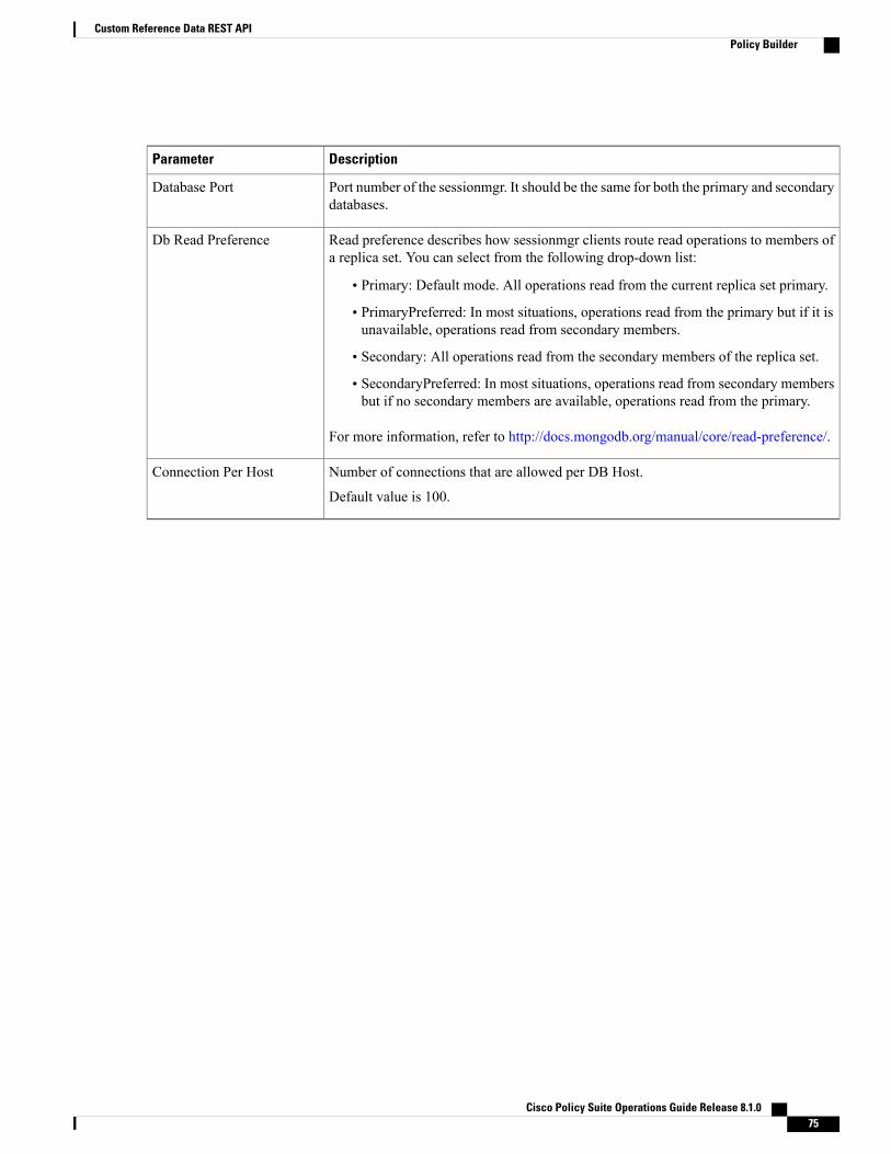
DescriptionParameter
Port number of the sessionmgr. It should be the same for both the primary and secondarydatabases.
Database Port
Read preference describes how sessionmgr clients route read operations to members ofa replica set. You can select from the following drop-down list:
• Primary: Default mode. All operations read from the current replica set primary.
• PrimaryPreferred: In most situations, operations read from the primary but if it isunavailable, operations read from secondary members.
• Secondary: All operations read from the secondary members of the replica set.
• SecondaryPreferred: In most situations, operations read from secondary membersbut if no secondary members are available, operations read from the primary.
For more information, refer to http://docs.mongodb.org/manual/core/read-preference/.
Db Read Preference
Number of connections that are allowed per DB Host.
Default value is 100.
Connection Per Host
Cisco Policy Suite Operations Guide Release 8.1.0 75
Custom Reference Data REST APIPolicy Builder
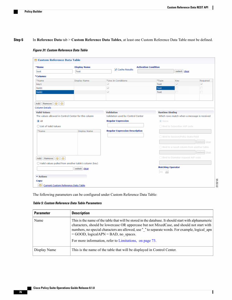
Step 6 In Reference Data tab > Custom Reference Data Tables, at least one Custom Reference Data Table must be defined.
Figure 31: Custom Reference Data Table
The following parameters can be configured under Custom Reference Data Table:
Table 5: Custom Reference Data Table Parameters
DescriptionParameter
This is the name of the table that will be stored in the database. It should start with alphanumericcharacters, should be lowercase OR uppercase but not MixedCase, and should not start withnumbers, no special characters are allowed, use “_” to separate words. For example, logical_apn= GOOD, logicalAPN = BAD, no_spaces.
For more information, refer to Limitations, on page 73.
Name
This is the name of the table that will be displayed in Control Center.Display Name
Cisco Policy Suite Operations Guide Release 8.1.076
Custom Reference Data REST APIPolicy Builder

DescriptionParameter
This indicates whether the tables should be cached in memory. This should be checked forproduction.
For more information, refer to Caching, on page 79.
Cache Results
This is the CustomReference Data Trigger which needs to be true before evaluating this table.This can be used to have multiple tables create the same data depending on conditions or toimprove performance if tables don't need to be evaluated based on an initial condition(s).
Activation Condition
If checked, this allows '*' to be used in the values of the data and the best matching row isreturned.
Best Match
This indicates the order the tables within the search table group should be evaluated. Startingwith 0 and increasing.
Evaluation Order
Columns correspond to the 'schema' for each columnwe're creating for this CustomReferenceData table.
• Name: The name of the column in the database.
• Display Name: A more readable display name.
• Use In Conditions: This represents whether this row will be available for conditions inPolicies or Use Case Templates. There is a performance cost to having these checked,so it is recommended to uncheck unless they are required.
Default value is checked (true).
• Type: the type determines what values will be allowed when creating them in controlcenter.
◦Text: The value is allowed to be any characters. For example, example123!.
◦Number: The value is allowed to be any whole number. For example, 1234.
◦Decimal: The value is allowed to be any number (including decimals). For example,1.234.
◦True/False: The value needs to be 'true' or 'false'. For example, true.
◦Date: The value is a date without a time component (May 17th, 2020).
◦DateTime: The value is a date + time (May 17th, 2020 5:00pm).
• Key: This indicates that this column is all or part of the 'key' for the table that makesthis row unique. By default, a key is required. Keys also are allowed set the RuntimeBinding fields to populate this data from the current message/session. Typically, keysare bound to data from the current session (APN, RAT Type) and other values are derivedfrom them. Keys can also be set to a value derived from another Custom Reference Datatable.
• Required: This indicates whether this field will be marked required in Control Center.A key is always required.
Columns
Cisco Policy Suite Operations Guide Release 8.1.0 77
Custom Reference Data REST APIPolicy Builder

DescriptionParameter
These are the valid values which will be allowed in Control Center (creates a list box).
• List of Valid Values: A list of name/display name pairs which will be used to create thelist. Valid values can also contain a 'name' which will be the actual value of the columnand a display value which allows Control Center to display an easier to use name.
• Valid Values pulled from another Table: This allows initializing the list based on anotherCustom Reference Data table. The 'name' value will be pulled from another table. Thereis no way to customize a 'display' name in this manner.
Valid Values
The validation set here will be checked by Control Center before allowing a row to be added.
• Regular Expression: This is the Java regular expression that will be run on the proposednew cell value to validate it as described inhttp://docs.oracle.com/javase/7/docs/api/java/util/regex/Pattern.html.
• Regular Expression Description: This is a message to the user indicating what the regularexpression is trying to check.
Validation
Runtime binding is how key column data gets filled out ('bound') from data in the currentsession. There are multiple ways to bind this data and it is also possible to set an operator todefine what should match (equals, less than, etc).
• Bind to Subscriber AVP Code: This pulls the value from an AVP on the subscriber. Itwill also pull values from a session AVP or a Policy Derived AVP.
• Bind to Session/Policy State Field: This pulls the value from a Policy State Data Retrieverwhich knows how to retrieve a single value for a session
• Bind to a Result Column from another Table: This allows the key to be filled out froma columns value from another table. This allows 'normalizing' the table structure andnot having on giant table with a lot of duplicated values.
• Bind to Diameter Request AVP code: This allows the key be filled out from an AVP onthe diameter request.
• Matching Operator: This allows the row to be 'matched' in other ways than having thevalue be 'equals'. Default value is equals.
◦eq: Equal
◦ne: Not Equal
◦gt: Greater than
◦gte: Greater than or equal
◦lt: Less than
◦lte: Less than or equal
Runtime Binding
Cisco Policy Suite Operations Guide Release 8.1.078
Custom Reference Data REST APIPolicy Builder

Architecture
MongoDBTheMongoDB database containing the CRD tables and the data is located in theMongoDB instance specifiedin the CRD plugin configuration.
The database is named cust_ref_data.
Two system collections exist in that database and do not actually contain CRD data:
• system.indexes— used by MongoDB. These are indices set on the database.
• crdversion— contains a document indicating the version of all the CRD tables you have defined. Theversion field increments by 1 every time you make a change or add data to any of your CRD tables.
A collection is created for each CRD table defined in Policy Builder.
• This collection contains a document for each row you define in the CRD table.
• Each document contains a field for each column you define in the CRD table.
• The field contains the value specified for the column for that row in the table.
• Additionally, there is a _id field which contains the internal key used by MongoDB and _version whichis used by CPS to provide optimistic locking protection, essentially to avoid two threads overwritingthe other's update, on the document.
An example is shown below:
Figure 32: CRD Table in Policy Builder
CachingSetting the Cache Results to true (checked) is the default and recommended settings in most cases as it yieldsthe best performance. Use of the cached copy also removes the dependency on the availability of the CRD
Cisco Policy Suite Operations Guide Release 8.1.0 79
Custom Reference Data REST APIArchitecture

database, so if there is an outage or performance issue, policy decisions utilizing the CRD data won't beimpacted.
The cached copy of the table is refreshed on CPS restart and whenever the API writes a change to the CRDtable, otherwise the cached copy is used and the database is not accessed.
API Endpoints and ExamplesThe URL used to access the CRD API are different depending on the type of deployment (High Availabilityor All-in-One):
High Availability (HA): https://<lbvip01>:8443/custrefdata/<tablename>/_<operation>
All-In-One (AIO): http://<ip>:8080/custrefdata/<tablename>/_<operation>
The examples in the following sections refer to the HA URL.
Query API
Purpose
Returns all rows currently defined in the specified table.
HTTP Operation Type
GET
Example URL
https://<lbvip01>:8443/custrefdata/test/_query
Example URL with Filtering
https://<lbvip01>:8443/custrefdata/test/_query?key1=Platinum
Payload
None, although parameters can be specified on the URL for filtering.
Response
Success returns code 200 Ok; XML indicating rows defined is returned. If the table does not exist, code 400Bad Request is returned.
Example Response without Filtering<rows><row><field code=”field1” value=”1004”/><field code=”field2” value=”testee”/><field code=”key1” value=”Platinum”/>
</row><row><field code=”field1” value=”1004”/><field code=”field2” value=”testee”/>
Cisco Policy Suite Operations Guide Release 8.1.080
Custom Reference Data REST APIAPI Endpoints and Examples
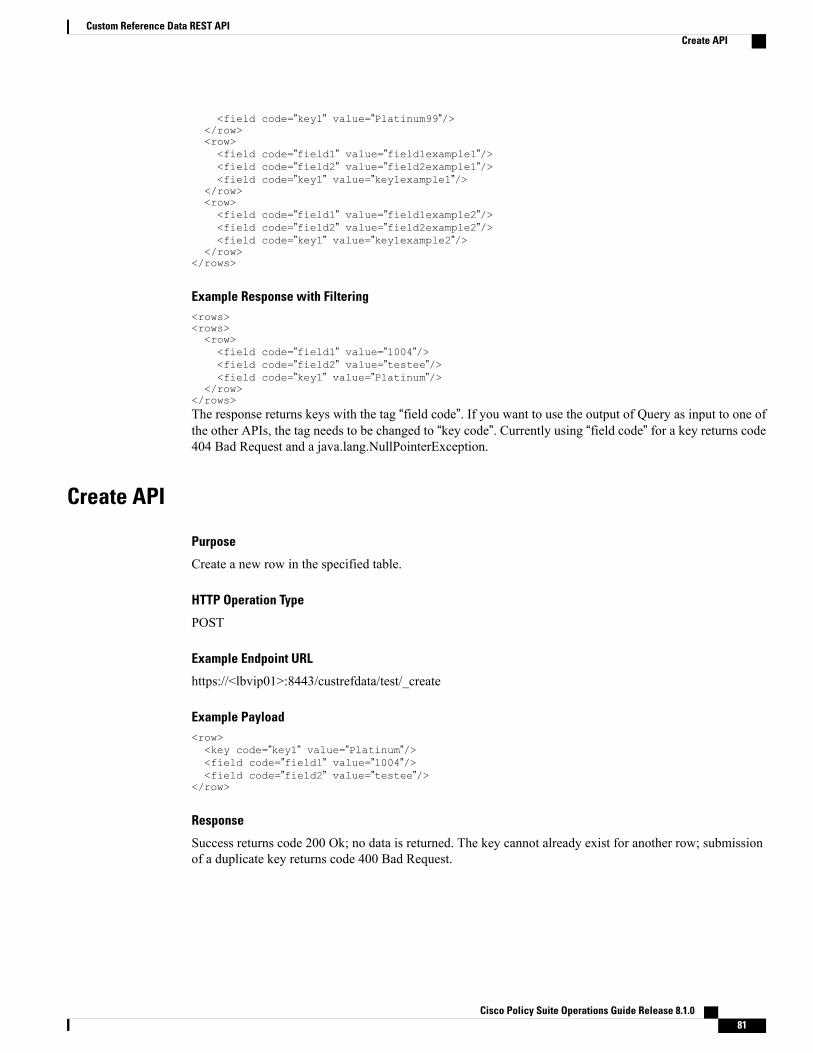
<field code=”key1” value=”Platinum99”/></row><row><field code=”field1” value=”field1example1”/><field code=”field2” value=”field2example1”/><field code=”key1” value=”key1example1”/>
</row><row><field code=”field1” value=”field1example2”/><field code=”field2” value=”field2example2”/><field code=”key1” value=”key1example2”/>
</row></rows>
Example Response with Filtering<rows><rows><row><field code=”field1” value=”1004”/><field code=”field2” value=”testee”/><field code=”key1” value=”Platinum”/>
</row></rows>The response returns keys with the tag “field code”. If you want to use the output of Query as input to one ofthe other APIs, the tag needs to be changed to “key code”. Currently using “field code” for a key returns code404 Bad Request and a java.lang.NullPointerException.
Create API
Purpose
Create a new row in the specified table.
HTTP Operation Type
POST
Example Endpoint URL
https://<lbvip01>:8443/custrefdata/test/_create
Example Payload<row><key code=”key1” value=”Platinum”/><field code=”field1” value=”1004”/><field code=”field2” value=”testee”/>
</row>
Response
Success returns code 200 Ok; no data is returned. The key cannot already exist for another row; submissionof a duplicate key returns code 400 Bad Request.
Cisco Policy Suite Operations Guide Release 8.1.0 81
Custom Reference Data REST APICreate API
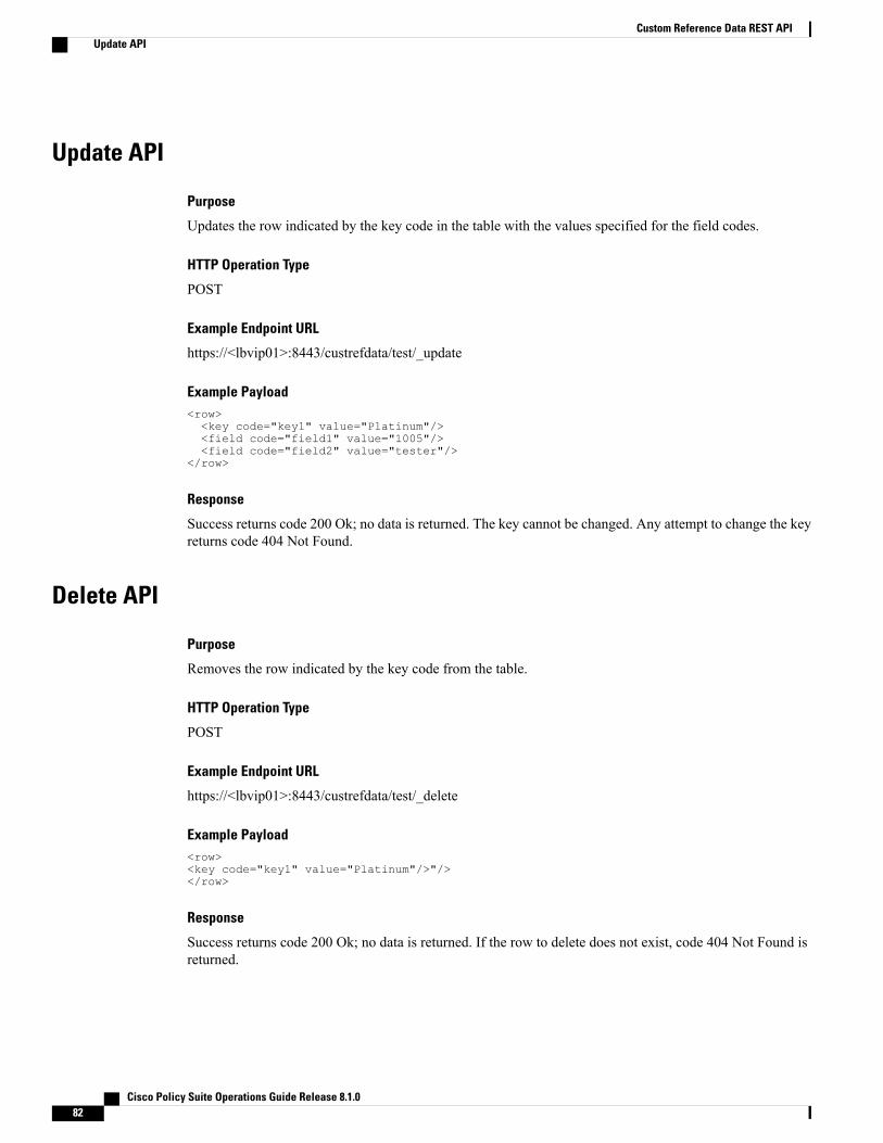
Update API
Purpose
Updates the row indicated by the key code in the table with the values specified for the field codes.
HTTP Operation Type
POST
Example Endpoint URL
https://<lbvip01>:8443/custrefdata/test/_update
Example Payload<row><key code="key1" value="Platinum"/><field code="field1" value="1005"/><field code="field2" value="tester"/>
</row>
Response
Success returns code 200 Ok; no data is returned. The key cannot be changed. Any attempt to change the keyreturns code 404 Not Found.
Delete API
Purpose
Removes the row indicated by the key code from the table.
HTTP Operation Type
POST
Example Endpoint URL
https://<lbvip01>:8443/custrefdata/test/_delete
Example Payload<row><key code="key1" value="Platinum"/>"/></row>
Response
Success returns code 200 Ok; no data is returned. If the row to delete does not exist, code 404 Not Found isreturned.
Cisco Policy Suite Operations Guide Release 8.1.082
Custom Reference Data REST APIUpdate API

Tips for UsageThe Query API is a GET operation which is the default operation that occurs when entering a URL into atypical web browser.
The POST operations, Create, Update, and Delete, require the use of a REST client so that the payload andcontent type can be specified in addition to the URL. REST clients are available for most web browsers asplug-ins or as part of web service tools, such as SoapUI. The content type when using these clients should bespecified as application/xml or the equivalent in the chosen tool.
Cisco Policy Suite Operations Guide Release 8.1.0 83
Custom Reference Data REST APITips for Usage

Cisco Policy Suite Operations Guide Release 8.1.084
Custom Reference Data REST APITips for Usage
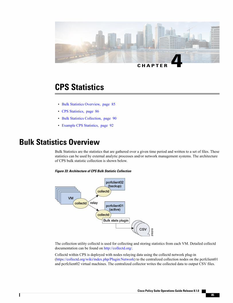
C H A P T E R 4CPS Statistics
• Bulk Statistics Overview, page 85
• CPS Statistics, page 86
• Bulk Statistics Collection, page 90
• Example CPS Statistics, page 92
Bulk Statistics OverviewBulk Statistics are the statistics that are gathered over a given time period and written to a set of files. Thesestatistics can be used by external analytic processes and/or network management systems. The architectureof CPS bulk statistic collection is shown below.
Figure 33: Architecture of CPS Bulk Statistic Collection
The collection utility collectd is used for collecting and storing statistics from each VM. Detailed collectddocumentation can be found on http://collectd.org/.
Collectd within CPS is deployed with nodes relaying data using the collectd network plug-in(https://collectd.org/wiki/index.php/Plugin:Network) to the centralized collection nodes on the pcrfclient01and pcrfclient02 virtual machines. The centralized collector writes the collected data to output CSV files.
Cisco Policy Suite Operations Guide Release 8.1.0 85

Each pcrfclient (01 and 02) collects bulk statistics independently. As a result, it is normal to have slightdifferences between the two files. For example, pcrfclient01 will generate a file at time t and pcrfclient02will generate a file at time t +/- the clock drift between the two machines.
Note
As a best practice, always use the bulk statistics collected from pcrfclient01. Pcrfclient02 can be used as abackup in the event of failure of pcrfclient01.
In the event that pcrfclient01 becomes unavailable, statistics will still be gathered on pcrfclient02. Statisticsdata is not synchronized between pcrfclient01 and pcrfclient02, so a gap would exist in the collected statisticswhile pcrfclient01 is down.
GrafanaFor more information about using Grafana, refer to the Cisco Policy Suite Operations Guide.
CPS StatisticsThe list of statistics available in CPS is consolidated in an Excel spreadsheet. After CPS is installed, thisspreadsheet can be found in the following location on the Cluster Manager VM:
/var/qps/install/current/scripts/documents/QPS_statistics.xlsx
OverviewThe following diagram represents the various statistic gathering points for incoming and outgoing messages.
Figure 34: Various Statistic Gathering Points for Incoming and Outgoing Messages
Measurements Legend
A – Inbound queue counts and times* B – policy action counts and times c – interface specific counts andtimes D – policy message counts and times E – outbound queue counts and times* F – round trip counts andtimes* * – statistics only apply to diameter messages
Cisco Policy Suite Operations Guide Release 8.1.086
CPS StatisticsGrafana

A brief description of each statistic gathering points is given below:
• Upon receipt of a message on the load balancer node the message is registered as received and forwardedto a middle tier processing node.
• This middle tier processing node tracks the inbound message counts and time spent within the inboundprocessing queue. If a message is discarded due to SLA violation, then counters are incremented at thispoint. This occurs at point A within the diagram.
• Upon arrival within the policy engine all messages are counted and timers are started to measure theduration of processing.
• Any internal or external actions are tracked at this point and the round trip time is measured from thepolicy engine invocation of the action and success or failure of the action. This occurs at point B withinthe diagram.
• For external actions (e.g. LDAP), interface specific statistics maybe captured. This occurs at point C inthe diagram and is gathered from the load balancer nodes.
• Upon completion of the message in the policy engine, the total elapsed time is measured and whethersuccess or failure occurred in processing.
A message is considered a success even if the policy returns an error (such as 5002).These application errors are tracked at point D within the diagram.
Note
• Outboundmessages are tracked from the policy engine to the load balancers at point E within the diagram.
• Upon receipt of outbound messages, the load balancers tracks either end to end completion time forinbound requests OR starts a timer and counts outbound requests. This occurs at point F within thediagram.
CPS Statistic TypesThis section describes various forms of statistics generated by CPS.
Diameter StatisticsIn Diameter statistics, Monitoring Areas are defined on the basis of Queues maintained in it. Diameter statisticscan also be defined based on whether the statistic is related to a counter or gauge.
• Counter: Counter type represents a non-negative integer which monotonically increases until it reachesa maximum value of 2^32-1 (4294967295 decimal), when it resets and starts increasing again from zero.
Counters have no defined “initial” value, and thus, a single value of a Counter has (in general) noinformation content. You must take a delta of multiple readings to understand anything.
• Gauge: Gauge type represents a non-negative integer, which can increase or decrease, but can neverexceed a maximum value, nor fall below a minimum value. The maximum value can not be greater than2^32-1 (4294967295 decimal), and the minimum value can not be smaller than 0.
Cisco Policy Suite Operations Guide Release 8.1.0 87
CPS StatisticsCPS Statistic Types
LDAP StatisticsCPS tracks LDAP statistics for general LDAP actions, LDAP query counters, LDAP connection counters, aswell as message counters.
Categories:
• Action
• Messages
RADIUS Server StatisticsRADIUS server statistics are defined based on two categories:
• Actions
• Messages
System StatisticsSystem statistics are defined based on six categories:
• CPU
• File System Usage
• Disk Performance
• Interface
• CPU Load
• Memory
Engine StatisticsEngine statistics are defined based on three categories:
• Session Count
• Session Operation
• Internal messages
MOG API StatisticsAPI statistics are defined based on five categories: Bearer Count, Tenant Onboarding Count, SubscriberOnboarding Count, Authentication Count and Callback Response Statistics.
Default and Dedicated Bearer Counters
Counter for the number of default and dedicated bearers related to API requests.
Cisco Policy Suite Operations Guide Release 8.1.088
CPS StatisticsCPS Statistic Types
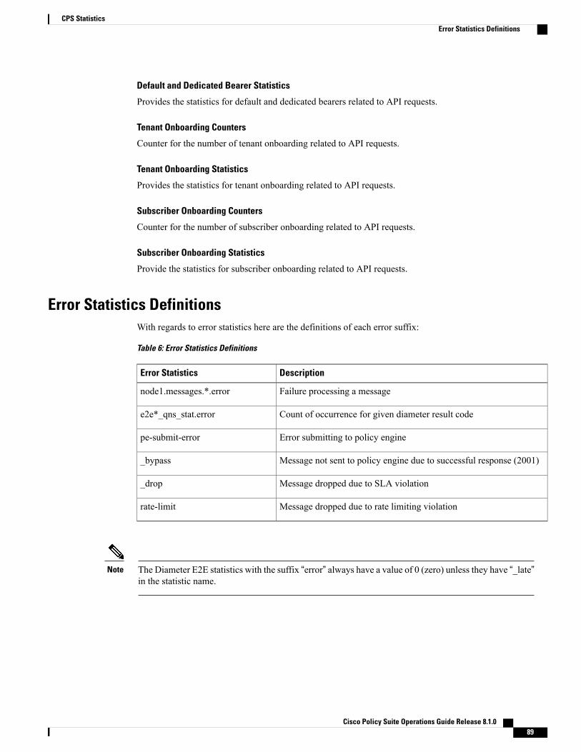
Default and Dedicated Bearer Statistics
Provides the statistics for default and dedicated bearers related to API requests.
Tenant Onboarding Counters
Counter for the number of tenant onboarding related to API requests.
Tenant Onboarding Statistics
Provides the statistics for tenant onboarding related to API requests.
Subscriber Onboarding Counters
Counter for the number of subscriber onboarding related to API requests.
Subscriber Onboarding Statistics
Provide the statistics for subscriber onboarding related to API requests.
Error Statistics DefinitionsWith regards to error statistics here are the definitions of each error suffix:
Table 6: Error Statistics Definitions
DescriptionError Statistics
Failure processing a messagenode1.messages.*.error
Count of occurrence for given diameter result codee2e*_qns_stat.error
Error submitting to policy enginepe-submit-error
Message not sent to policy engine due to successful response (2001)_bypass
Message dropped due to SLA violation_drop
Message dropped due to rate limiting violationrate-limit
The Diameter E2E statistics with the suffix “error” always have a value of 0 (zero) unless they have “_late”in the statistic name.
Note
Cisco Policy Suite Operations Guide Release 8.1.0 89
CPS StatisticsError Statistics Definitions

Bulk Statistics CollectionBy default, CPS outputs a bulk statistics CSV file to the /var/broadhop/stats/ directory on the pcrfclient01 andpcrfclient02 VMs in five minute intervals.
The default naming standard is bulk-hostname-YYYY-MM-DD-HH-MI.csv
These CSV files include all statistics collected from all VMs during the 5 minute interval.
If a statistic is generated by the system multiple times within the 5 minute interval, only the last measuredstatistic is collected in the CSV file.
Note
The following list is a sample of the file names created in the /var/broadhop/stats/ directory on the pcrfclient01VM.
[root@pcrfclient01 stats]# pwd/var/broadhop/stats[root@pcrfclient01 stats]# lsbulk-pcrfclient01-201510131350.csvbulk-pcrfclient01-201510131355.csvbulk-pcrfclient01-201510131400.csvbulk-pcrfclient01-201510131405.csvbulk-pcrfclient01-201510131410.csvbulk-pcrfclient01-201510131415.csvbulk-pcrfclient01-201510131420.csvbulk-pcrfclient01-201510131425.csvbulk-pcrfclient01-201510131430.csvbulk-pcrfclient01-201510131435.csvbulk-pcrfclient01-201510131440.csvbulk-pcrfclient01-201510131445.csvbulk-pcrfclient01-201510131450.csvbulk-pcrfclient01-201510131455.csvbulk-pcrfclient01-201510131500.csvbulk-pcrfclient01-201510131505.csvbulk-pcrfclient01-201510131510.csvbulk-pcrfclient01-201510131515.csvbulk-pcrfclient01-201510131520.csvbulk-pcrfclient01-201510131525.csvbulk-pcrfclient01-201510131530.csvbulk-pcrfclient01-201510131535.csvbulk-pcrfclient01-201510131540.csvbulk-pcrfclient01-201510131545.csvbulk-pcrfclient01-201510131550.csvbulk-pcrfclient01-201510131555.csvbulk-pcrfclient01-201510131600.csvbulk-pcrfclient01-201510131605.csvbulk-pcrfclient01-201510131610.csvbulk-pcrfclient01-201510131615.csvbulk-pcrfclient01-201510131620.csvbulk-pcrfclient01-201510131625.csvbulk-pcrfclient01-201510131630.csv
Configuring the CSV File Generation IntervalBy default, CSV files are generated every 5 minutes. To change this interval:
Step 1 Add the following line to /etc/broadhop/qns.conf file:Dstatistics.step.interval=X
Cisco Policy Suite Operations Guide Release 8.1.090
CPS StatisticsBulk Statistics Collection

The value X is a multiplier of 10 seconds. For example, a value of 1 = 10 second interval; a value of 2 = 20 secondinterval.
Step 2 Any changes made in the qns.conf file need to be deployed to all qns VMs and then a rolling restart on all qns VMs isrequired to apply the changes in the qns.conf file:a) Run copyall.sh to push the qns.conf file out to each qns node.b) Run the following command during a maintenance window:
restartall.sh
Changing the interval to a lower value allows for easier identification of peaks and valleys in response time.However, only the last statistic measured during a 5 minute period is reported in the CSV file and this factshould be taken into account when interpreting the bulk statistics.
Retention of CSV FilesCPS retains each bulk statistic CSV file on the pcrfclient01/02 VM for 2 days, after which the file isautomatically removed. If you need to preserve these CSV files, you must back up or move them to an alternatesystem.
Configuring Logback.xmlConfiguration of the CPS application statistics is controlled in the /etc/collectd.d/logback.xml file.
Refer to http://logback.qos.ch/manual/appenders.html for more information about the configuration of thelogback.xml file.
Restarting the Collectd ServiceAfter making any configuration changes to logback.xml, restart the collectd service:
service collectd restart
Adding Realm Names to Diameter StatisticsBy default, the diameter statistics that are generated do not include the realm names. To include realms in thestatistics collected, add the following line in the qns.conf file (comma separated auth-appl-id).
-Ddiameter.appid.realm.stats=Auth-Appl-Id-1,Auth-Appl-Id-2,… Auth-Appl-Id-n
where each Auth-Appl-Id refers to the specific protocol's Auth-Application-Id for which realms are neededin the statistics.
For example, to add Gx, Gy, Rx and Sy realms to the statistic names, use the following Auth-Appl-Ids:
-Ddiameter.appid.realm.stats=16777238,16777235,16777236,9
where
Cisco Policy Suite Operations Guide Release 8.1.0 91
CPS StatisticsRetention of CSV Files

• Gx Auth-Application-ID = 16777238
• Rx Auth-Application-ID = 16777236
• Gy Auth-Application-ID = 4
• Sy Auth-Application-ID = 7
Adding a realmwill increase the number of statistics generated/collected. Add realms only when necessary.Note
As an example, statistic names with and without the realms are shown below for reference for the followingstatistic:
e2e_<domain>_[realm_][alias_]<message id>
Counter name with Realm (with qns.conf file modification):
C,lb02,node2.messages.e2e_PHONE_sy-ac.cisco.com_AC_Syp_AAR_2001.qns_stat.success,528
C,lb02.node2.messages.e2e_PHONE_sy-bm.cisco.com_BM_Syp_AAR_2001.qns_stat.success,1221
Counter name without Realm (without qns.conf file modification):
C,lb01,node2.messages.e2e_PHONE_AC_Syp_AAR_2001.qns_stat.success,1495
C,lb01,node2.messages.e2e_PHONE_BM_Syp_AAR_2001.qns_stat.success,4
Each statistic field has a fixed maximum length of 63 characters. Based on the current syntax, the length ofthe realm should not exceed 16 characters, otherwise it will lead to truncation of the counter name.
Example CPS Statistics
Sample CSV FilesThe following list is a sample of the file names created in the /var/broadhop/stats directory on the pcrfclient01VM.[root@pcrfclient01 stats]# pwd
/var/broadhop/stats[root@pcrfclient01 stats]# lsbulk-pcrfclient01-201510131350.csvbulk-pcrfclient01-201510131355.csvbulk-pcrfclient01-201510131400.csvbulk-pcrfclient01-201510131405.csvbulk-pcrfclient01-201510131410.csvbulk-pcrfclient01-201510131415.csvbulk-pcrfclient01-201510131420.csvbulk-pcrfclient01-201510131425.csvbulk-pcrfclient01-201510131430.csvbulk-pcrfclient01-201510131435.csvbulk-pcrfclient01-201510131440.csvbulk-pcrfclient01-201510131445.csvbulk-pcrfclient01-201510131450.csvbulk-pcrfclient01-201510131455.csvbulk-pcrfclient01-201510131500.csvbulk-pcrfclient01-201510131505.csvbulk-pcrfclient01-201510131510.csvbulk-pcrfclient01-201510131515.csvbulk-pcrfclient01-201510131520.csvbulk-pcrfclient01-201510131525.csv
Cisco Policy Suite Operations Guide Release 8.1.092
CPS StatisticsExample CPS Statistics

bulk-pcrfclient01-201510131530.csvbulk-pcrfclient01-201510131535.csvbulk-pcrfclient01-201510131540.csvbulk-pcrfclient01-201510131545.csvbulk-pcrfclient01-201510131550.csvbulk-pcrfclient01-201510131555.csvbulk-pcrfclient01-201510131600.csvbulk-pcrfclient01-201510131605.csvbulk-pcrfclient01-201510131610.csvbulk-pcrfclient01-201510131615.csvbulk-pcrfclient01-201510131620.csvbulk-pcrfclient01-201510131625.csvbulk-pcrfclient01-201510131630.csv
Sample OutputA sample bulk statistics .csv file is shown below:C,node3.messagesmessages.e2e_Mobile_cisco.com_Gx_CCR-I_2001.qns_stat.success,99254C,node3.messages.e2e_Mobile_cisco.com_Gx_CCR-I_2001.qns_stat.error,0D,node3.messages.e2e_Mobile_cisco.com_Gx_CCR-I_2001.qns_stat.total_time_in_ms,1407G,node3.messages.e2e_Mobile_cisco.com_Gx_CCR-I_2001.qns_stat.avg,0.0C,node3.messages.e2e_cisco.com_Gx_RAR_late_5xxx.qns_stat.success,0C,node3.messages.e2e_cisco.com_Gx_RAR_late_5xxx.qns_stat.error,99294D,node3.messages.e2e_cisco.com_Gx_RAR_late_5xxx.qns_stat.total_time_in_ms,0G,node3.messages.e2e_cisco.com_Gx_RAR_late_5xxx.qns_stat.avg,0.0C,node3.messages.e2e_cisco.com_Gx_CCR-I_late_2001.qns_stat.success,0C,node3.messages.e2e_cisco.com_Gx_CCR-I_late_2001.qns_stat.error,40D,node3.messages.e2e_cisco.com_Gx_CCR-I_late_2001.qns_stat.total_time_in_ms,0G,node3.messages.e2e_cisco.com_Gx_CCR-I_late_2001.qns_stat.avg,0.0C,node3.messages.e2e_cisco.com_Gx_RAR_late_5002.qns_stat.success,0C,node3.messages.e2e_cisco.com_Gx_RAR_late_5002.qns_stat.error,99294D,node3.messages.e2e_cisco.com_Gx_RAR_late_5002.qns_stat.total_time_in_ms,0G,node3.messages.e2e_cisco.com_Gx_RAR_late_5002.qns_stat.avg,0.0C,node4.messages.e2e_Mobile_Sy_STR_2001.qns_stat.success,99290C,node4.messages.e2e_Mobile_Sy_STR_2001.qns_stat.error,0D,node4.messages.e2e_Mobile_Sy_STR_2001.qns_stat.total_time_in_ms,235G,node4.messages.e2e_Mobile_Sy_STR_2001.qns_stat.avg,0.0C,node4.messages.e2e_Mobile_Sy_SLR_2001.qns_stat.success,99290C,node4.messages.e2e_Mobile_Sy_SLR_2001.qns_stat.error,0D,node4.messages.e2e_Mobile_Sy_SLR_2001.qns_stat.total_time_in_ms,182G,node4.messages.e2e_Mobile_Sy_SLR_2001.qns_stat.avg,0.0C,node3.messages.e2e_Mobile_cisco.com_Gx_CCR-I_2001.qns_stat.success,99254C,node3.messages.e2e_Mobile_cisco.com_Gx_CCR-I_2001.qns_stat.error,0D,node3.messages.e2e_Mobile_cisco.com_Gx_CCR-I_2001.qns_stat.total_time_in_ms,1407G,node3.messages.e2e_Mobile_cisco.com_Gx_CCR-I_2001.qns_stat.avg,0.0C,node3.messages.e2e_cisco.com_Gx_RAR_late_5xxx.qns_stat.success,0C,node3.messages.e2e_cisco.com_Gx_RAR_late_5xxx.qns_stat.error,99294D,node3.messages.e2e_cisco.com_Gx_RAR_late_5xxx.qns_stat.total_time_in_ms,0
Cisco Policy Suite Operations Guide Release 8.1.0 93
CPS StatisticsSample Output
Cisco Policy Suite Operations Guide Release 8.1.094
CPS StatisticsSample Output
C H A P T E R 5Fault List
• Overview, page 95
• Configuration, page 96
OverviewThe Fault list configuration in Policy builder allows configuring the thresholds at which License UsageThreshold Exceeded traps are sent out. The default recommended values are: Critical 95, Major 90, Minor 85andWarning 80 which would result in traps being sent at 80, 85, 90 and 95 percent for License Usage ThresholdLimits.
For example, if the license limit is 10000 sessions and there are 9600 active sessions, configuring the thresholdat 95 and type as Critical would generate a Critical trap whose message is Session Count License Usage at96%, exceeding threshold: 95%.
Cisco Policy Suite Operations Guide Release 8.1.0 95
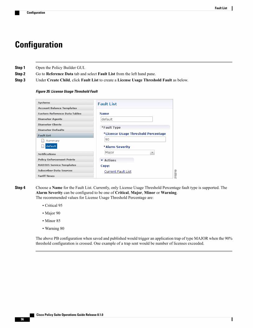
Configuration
Step 1 Open the Policy Builder GUI.Step 2 Go to Reference Data tab and select Fault List from the left hand pane.Step 3 Under Create Child, click Fault List to create a License Usage Threshold Fault as below.
Figure 35: License Usage Threshold Fault
Step 4 Choose a Name for the Fault List. Currently, only License Usage Threshold Percentage fault type is supported. TheAlarm Severity can be configured to be one of Critical,Major,Minor orWarning.The recommended values for License Usage Threshold Percentage are:
• Critical 95
• Major 90
• Minor 85
•Warning 80
The above PB configuration when saved and published would trigger an application trap of type MAJOR when the 90%threshold configuration is crossed. One example of a trap sent would be number of licenses exceeded.
Cisco Policy Suite Operations Guide Release 8.1.096
Fault ListConfiguration
Validation Steps
Step 1 Configure a Threshold Limit as explained above in PB.Step 2 Generate active sessions exceeding the configured threshold limit.Step 3 Validate the Traps are received on the configured trap receiver for the defined limit and Severity.
Cisco Policy Suite Operations Guide Release 8.1.0 97
Fault ListValidation Steps

Cisco Policy Suite Operations Guide Release 8.1.098
Fault ListValidation Steps

C H A P T E R 6Expanding an HA Deployment
• Overview, page 99
• Typical Scenarios When Expansion is Necessary, page 99
• Hardware Approach to Expanding, page 100
• Component (VM Node) Approach to Expanding, page 100
OverviewThe CPS solution is a robust and scalable software-based solution that can be expanded by adding additionalhardware and software components. The following sections explain typical scenarios of when to expand thehardware and software to effect such growth.
Typical Scenarios When Expansion is NecessaryYour network may grow for the following reasons:
• The subscriber base has grown or will grow beyond the initial installation specifications.
In this case, the number of active or non-active subscribers becomes larger than the initial deployment.This can cause one or more components to reach capacity. New components must be added toaccommodate the growth.
• The services or subscriber scenarios have changed, or new services have been introduced, and thetransactions per second on a component no longer meet requirements.
When a new service or scenario occurs, often there is a change in the overall Transactions Per Second(TPS), or in the TPS on a specific component. When this occurs, new components are necessary tohandle the new load.
• The operator notices that there are factors outside of the initial design that are causing either the overallsystem or a specific component to have a high resource load.
This may cause one or multiple components to reach its capacity for TPS. When this occurs, newcomponents are necessary to handle the new factors.
Cisco Policy Suite Operations Guide Release 8.1.0 99

Hardware Approach to ExpandingAdding a new component may require adding additional hardware. However, the addition of more hardwaredepends on the physical resources already available, plus what is needed for the new component.
If the number of subscribers exceeds 10 million, then the customer needs to Clone and Repartition sessionmgrDisks. See Cloning and Repartitioning sessionmgr Disks, on page 103.
High Availability ConsequencesWhen adding more hardware, the design must take into consideration the high availability (HA) needs of thesystem. The HA design for a single-site system is N+1 at the hardware and application level. As a result,adding a new blade incrementally increases the HA capacity of the system.
For example, in a basic installation there are 2 Cisco Policy Server blades handling the traffic. The solutionis designed so that if one of the blades fails, the other blade can handle the entire capacity of the system.Whenadding a third blade for capacity expansion, there are now 2 blades to handle the system load if one of theblades fails. This allows for a more linear scaling approach because each additional blade can be accountablefor being able to use its full capacity.
When adding new blades to a cluster, the blades in the cluster must be co-located to achieve the properthroughput between other components.
Note
Adding a New Blade
Step 1 Install ESX server to the blade.Step 2 Open the CPS Deployment Template spreadsheet. This spreadsheet should have been created and maintained during the
initial deployment.Step 3 In the Additional Hosts sheet, add an entry for the new ESX server with IP, Host name and Alias.Step 4 Save the CSV file and transfer it to the following directory on the Cluster Manager /var/qps/config/deploy/csvStep 5 Run /var/qps/install/current/scripts/import/import_deploy.sh to convert the csv to json.
Component (VM Node) Approach to ExpandingThe most common components to be expanded are on the Cisco Policy Servers. As your system begins toscale up, you will need to add more CPS nodes and more SessionMgrs. Expansion for other components canfollow the same pattern as described here. The next sections discuss the configurations needed for thosespecific components to be active in the system.
Cisco Policy Suite Operations Guide Release 8.1.0100
Expanding an HA DeploymentHardware Approach to Expanding

Adding Additional Component
Step 1 Modify the CPS Deployment Template spreadsheet (this spreadsheet should have been created and maintained duringthe initial deployment).
Step 2 In the Hosts sheet, add the new VM node with the parameters. See the CPS Installation Guide for details about eachcolumn.
Step 3 Save the CSV file and transfer it to the following directory on the Cluster Manager /var/qps/config/deploy/csv.Step 4 Run /var/qps/install/current/scripts/import/import_deploy.sh to convert the csv to json.Step 5 Deploy the new VM using /var/qps/install/current/scripts/deployer/deploy.sh xxx, where xxx is the alias of
the new VM to be deployed.Refer to the CPS Installation Guide for more details about using deploy.sh.
Cisco Policy Suite Operations Guide Release 8.1.0 101
Expanding an HA DeploymentAdding Additional Component

Cisco Policy Suite Operations Guide Release 8.1.0102
Expanding an HA DeploymentAdding Additional Component

C H A P T E R 7Cloning and Repartitioning sessionmgr Disks
• Cloning and Repartitioning sessionmgr Disks, page 103
• Cloning and Disk Repartitioning of Sessionmgr01 VM, page 103
• Cloning and Disk Repartitioning of Sessionmgr02 VM, page 107
Cloning and Repartitioning sessionmgr Disks
Cloning and Disk Repartitioning of Sessionmgr01 VM
Clone Sessionmgr01 VMDowntime: No downtime
Before You Begin
• Before disk repartition, clone sessionmgr01. This step is optional but to reduce the risk of losing thedata during disk repartitioning, the customer can take the backup of sessionmgr01 VM. If the customerdoes not have enough space to take the backup this step can be ignored.
• Blade with enough space to hold cloned image of sessionmgr01.
Step 1 Login to vSphere Client on sessionmgr01 blade with administrator credentials.Step 2 Right-click sessionmgr01 and select Clone > Choose appropriate inventory in which blade resides > Choose the blade
with enough space to hold sessionmgr01 image > Next > Next > Finish.Step 3 Cloning starts. Wait for it to finish the process.
Cisco Policy Suite Operations Guide Release 8.1.0 103
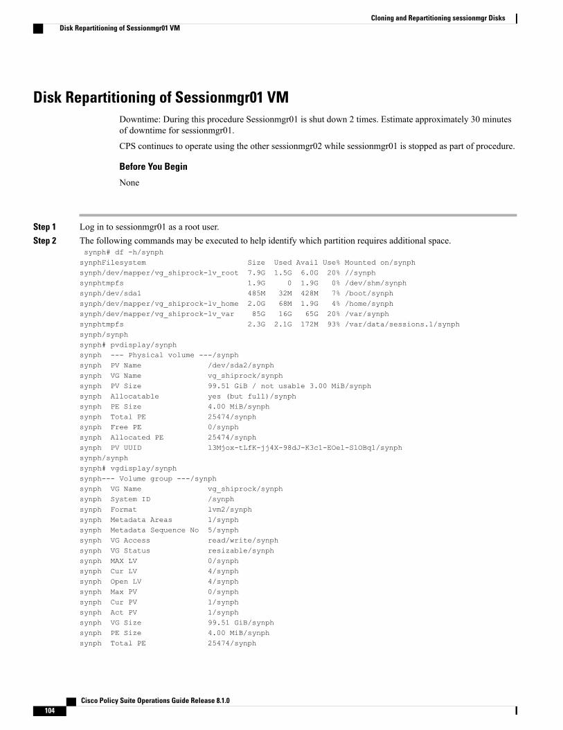
Disk Repartitioning of Sessionmgr01 VMDowntime: During this procedure Sessionmgr01 is shut down 2 times. Estimate approximately 30 minutesof downtime for sessionmgr01.
CPS continues to operate using the other sessionmgr02 while sessionmgr01 is stopped as part of procedure.
Before You Begin
None
Step 1 Log in to sessionmgr01 as a root user.Step 2 The following commands may be executed to help identify which partition requires additional space.
synph# df -h/synphsynphFilesystem Size Used Avail Use% Mounted on/synphsynph/dev/mapper/vg_shiprock-lv_root 7.9G 1.5G 6.0G 20% //synphsynphtmpfs 1.9G 0 1.9G 0% /dev/shm/synphsynph/dev/sda1 485M 32M 428M 7% /boot/synphsynph/dev/mapper/vg_shiprock-lv_home 2.0G 68M 1.9G 4% /home/synphsynph/dev/mapper/vg_shiprock-lv_var 85G 16G 65G 20% /var/synphsynphtmpfs 2.3G 2.1G 172M 93% /var/data/sessions.1/synphsynph/synphsynph# pvdisplay/synphsynph --- Physical volume ---/synphsynph PV Name /dev/sda2/synphsynph VG Name vg_shiprock/synphsynph PV Size 99.51 GiB / not usable 3.00 MiB/synphsynph Allocatable yes (but full)/synphsynph PE Size 4.00 MiB/synphsynph Total PE 25474/synphsynph Free PE 0/synphsynph Allocated PE 25474/synphsynph PV UUID l3Mjox-tLfK-jj4X-98dJ-K3c1-EOel-SlOBq1/synphsynph/synphsynph# vgdisplay/synphsynph--- Volume group ---/synphsynph VG Name vg_shiprock/synphsynph System ID /synphsynph Format lvm2/synphsynph Metadata Areas 1/synphsynph Metadata Sequence No 5/synphsynph VG Access read/write/synphsynph VG Status resizable/synphsynph MAX LV 0/synphsynph Cur LV 4/synphsynph Open LV 4/synphsynph Max PV 0/synphsynph Cur PV 1/synphsynph Act PV 1/synphsynph VG Size 99.51 GiB/synphsynph PE Size 4.00 MiB/synphsynph Total PE 25474/synph
Cisco Policy Suite Operations Guide Release 8.1.0104
Cloning and Repartitioning sessionmgr DisksDisk Repartitioning of Sessionmgr01 VM

synph Alloc PE / Size 25474 / 99.51 GiB/synphsynph Free PE / Size 0 / 0 /synphsynph VG UUID P1ET44-jiEI-DIbd-baYt-fVom-bhUn-zgs5Fz/synph
• (df -h): /var is /dev/mapper/vg_shiprock-lv_var. This is equivalent to device /dev/vg_shiprock/lv_var.
• (pvdisplay): vg_shiprock (used by lv_var which is /var) is on /dev/sda2.
Step 3 Execute the fdisk command to check the disk size.# fdisk -l /dev/sda
Disk /dev/sda: 107.4 GB, 107374182400 bytes255 heads, 63 sectors/track, 13054 cylindersUnits = cylinders of 16065 * 512 = 8225280 bytesSector size (logical/physical): 512 bytes / 512 bytesI/O size (minimum/optimal): 512 bytes / 512 bytesDisk identifier: 0x0008dcae
Device Boot Start End Blocks Id System/dev/sda1 * 1 64 512000 83 LinuxPartition 1 does not end on cylinder boundary./dev/sda2 64 13055 104344576 8e Linux LVM
Step 4 Power down the Virtual Machine.# shutdown -h now
If cloning is not possible because of space limitation on Blade, backup of sessionmgr01 VM can be taken bysaving OVF of sessionmgr01 VM to local storage like Laptop, Desktop. (Both cloning and OVF backup areoptional steps, but either one of them is highly recommended.)
Note
Step 5 Log in using the VMWare vSphere Client as an administrator (e.g. root) to the ESXi host which has your Linux VirtualMachine on it.
Step 6 Right-click on the Virtual Machine and select Edit Settings > Click Hard Disk 1 > Increase the Provisioned Size of theHard Disk.
Step 7 Power ON the Virtual Machine.Step 8 Log in (ssh) to the Virtual Machine as root user.Step 9 Confirm that disk space has been added to the /dev/sda partition.
# fdisk -l /dev/sda
Disk /dev/sda: 70.5 GB, 79529246720 bytes255 heads, 63 sectors/track, 9668 cylindersUnits = cylinders of 16065 * 512 = 8225280 bytes
Step 10 Execute the following commands (Bold Characters indicates actual inputs from user (all of them are in lower case).# fdisk /dev/sdaThe number of cylinders for this disk is set to 7832.There is nothing wrong with that, but this is larger than 1024,and could in certain setups cause problems with:1) software that runs at boot time (e.g., old versions of LILO)2) booting and partitioning software from other OSs
(e.g., DOS FDISK, OS/2 FDISK)Command (m for help): pDisk /dev/sda: 64.4 GB, 64424509440 bytes255 heads, 63 sectors/track, 7832 cylindersUnits = cylinders of 16065 * 512 = 8225280 bytes
Cisco Policy Suite Operations Guide Release 8.1.0 105
Cloning and Repartitioning sessionmgr DisksDisk Repartitioning of Sessionmgr01 VM
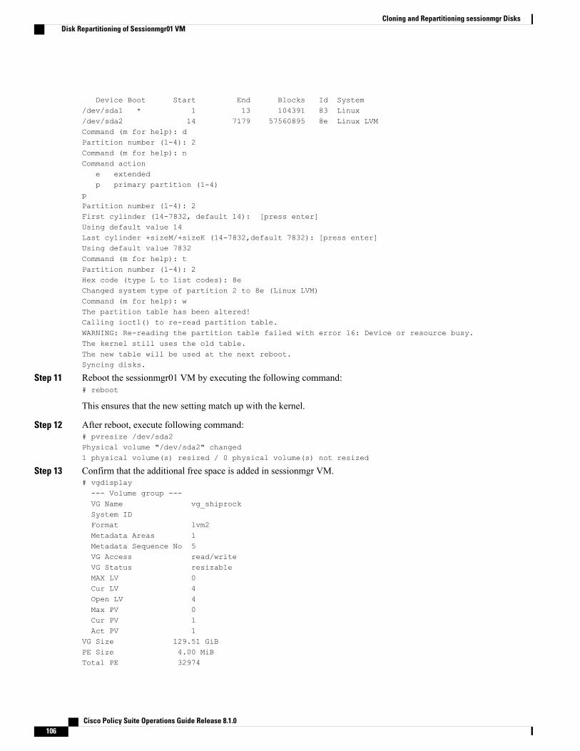
Device Boot Start End Blocks Id System/dev/sda1 * 1 13 104391 83 Linux/dev/sda2 14 7179 57560895 8e Linux LVMCommand (m for help): dPartition number (1-4): 2Command (m for help): nCommand action
e extendedp primary partition (1-4)
pPartition number (1-4): 2First cylinder (14-7832, default 14): [press enter]Using default value 14Last cylinder +sizeM/+sizeK (14-7832,default 7832): [press enter]Using default value 7832Command (m for help): tPartition number (1-4): 2Hex code (type L to list codes): 8eChanged system type of partition 2 to 8e (Linux LVM)Command (m for help): wThe partition table has been altered!Calling ioctl() to re-read partition table.WARNING: Re-reading the partition table failed with error 16: Device or resource busy.The kernel still uses the old table.The new table will be used at the next reboot.Syncing disks.
Step 11 Reboot the sessionmgr01 VM by executing the following command:# reboot
This ensures that the new setting match up with the kernel.
Step 12 After reboot, execute following command:# pvresize /dev/sda2Physical volume "/dev/sda2" changed1 physical volume(s) resized / 0 physical volume(s) not resized
Step 13 Confirm that the additional free space is added in sessionmgr VM.# vgdisplay--- Volume group ---VG Name vg_shiprockSystem IDFormat lvm2Metadata Areas 1Metadata Sequence No 5VG Access read/writeVG Status resizableMAX LV 0Cur LV 4Open LV 4Max PV 0Cur PV 1Act PV 1
VG Size 129.51 GiBPE Size 4.00 MiBTotal PE 32974
Cisco Policy Suite Operations Guide Release 8.1.0106
Cloning and Repartitioning sessionmgr DisksDisk Repartitioning of Sessionmgr01 VM

Alloc PE / Size 25474 / 99.51 GiBFree PE / Size 7500 / 30.00 GBVG UUID pPSNBU-FRWO-z3aC-iAxS-ewaw-jOFT-dTcBKd
Step 14 Verify that the /var partition is mounted on /dev/mapper/vg_shiprock-lv_var.#df -hFilesystem Size Used Avail Use% Mounted on/dev/mapper/vg_shiprock-lv_root
18G 2.5G 15G 15% //dev/mapper/vg_shiprock-lv_home
5.7G 140M 5.3G 3% /home/dev/mapper/vg_shiprock-lv_var
85G 16G 65G 20% /var/dev/sda1 99M 40M 55M 43% /boottmpfs 16G 0 16G 0% /dev/shmtmpfs 8.0G 1.1G 7.0G 14% /data/sessions.1
Step 15 Extend /var partition to take up additional free space.#lvextend -l +100%FREE /dev/mapper/vg_shiprock-lv_varExtending logical volume lv_var to 120.00 GBLogical volume lv_var successfully resized
Step 16 Check the newly added space in /dev/mapper/vg_shiprock-lv_var.# lvdisplay
Step 17 Add space to VM file system.# resize2fs /dev/mapper/vg_shiprock-lv_varresize2fs 1.39 (29-May-2006)Filesystem at /dev/mapper/vg_shiprock-lv_var is mounted on /var; on-line resizing requiredPerforming an on-line resize of /dev/mapper/vg_shiprock-lv_var to 6553600 (4k) blocks.The filesystem on /dev/mapper/vg_shiprock-lv_var is now 6553600 blocks long.
Step 18 Check the increased size of /var partition.# df -hFilesystem Size Used Avail Use% Mounted on/dev/mapper/vg_shiprock-lv_root
23G 2.1G 20G 10% //dev/mapper/vg_shiprock-lv_home
5.7G 140M 5.3G 3% /home/dev/mapper/vg_shiprock-lv_var
130G 16G 95G 12% /var/dev/sda1 99M 40M 55M 43% /boottmpfs 2.0G 0 2.0G 0% /dev/shm
Cloning and Disk Repartitioning of Sessionmgr02 VMRepeat Clone Sessionmgr01 VM, on page 103 and Disk Repartitioning of Sessionmgr01 VM, on page 104on sessionmgr02 for cloning and disk repartitioning of sessionmgr02 VM.
Cisco Policy Suite Operations Guide Release 8.1.0 107
Cloning and Repartitioning sessionmgr DisksCloning and Disk Repartitioning of Sessionmgr02 VM
Cisco Policy Suite Operations Guide Release 8.1.0108
Cloning and Repartitioning sessionmgr DisksCloning and Disk Repartitioning of Sessionmgr02 VM

C H A P T E R 8CPS Commands
• CPS Commands, page 110
• about.sh, page 110
• adduser.sh, page 110
• auditrpms.sh, page 111
• build_all.sh, page 111
• build_etc.sh, page 113
• build_set.sh, page 113
• capture_env.sh, page 114
• change_passwd.sh, page 114
• cleanup_license.sh, page 115
• copytoall.sh, page 115
• diagnostics.sh, page 116
• list_installed_features.sh, page 117
• reinit.sh, page 119
• restartall.sh, page 119
• restartqns.sh, page 120
• runonall.sh, page 120
• service, page 120
• session_cache_ops.sh, page 121
• startall.sh, page 123
• startqns.sh, page 124
• statusall.sh, page 124
• stopall.sh, page 126
• stopqns.sh, page 126
Cisco Policy Suite Operations Guide Release 8.1.0 109

• summaryall.sh, page 127
• syncconfig.sh, page 129
• top_qps.sh, page 129
• vm-init.sh, page 131
CPS CommandsThis chapter provides descriptions of CPS administrative commands.
about.shThis command displays core, patch, and feature software version information andURLs to the various interfacesand APIs for the deployment.
Syntax
/var/qps/bin/diag/about.sh [-h]
Executable on VMs
• Cluster Manager
• pcrfclient01/02
adduser.shThis utility adds a new user to the specified nodes that are part of the CPS deployment. These accounts willbe provisioned without shell access and, as such, they're only useful for authenticating against the variousweb-based GUIs used to administrate CPS.
The hosts that get provisioned with these new accounts can be selected using the 'node-regex' option. Thedefault regular expression used by the script is:node-regex ::= ^(pcrfclient|qns|lb[0-9]+|sessionmgr)
Syntax
/var/qps/bin/support/adduser.sh [-h] [node-regex]
When prompted for the user’s group, set ‘qns-svn’ for read-write permissions or ‘qns-ro’ for read-onlypermissions.
To add a user with 'read/write' access to Control Center, their group should be 'qns'.
• To check if a user already exists, login in as root and enter ‘su <username>’.
• To check a user’s ‘groups’, enter ‘groups <username>’.
Cisco Policy Suite Operations Guide Release 8.1.0110
CPS CommandsCPS Commands

Executable on VMs
All
Example[root@host /]# /var/qps/bin/support/adduser.shEnter username: usernameEnter group for the user: groupnameEnter password: passwordRe-enter password: passwordThe above example adds username to all the VMs in the cluster.
auditrpms.shThis script runs in background on all VMs except Cluster Manager. This script/daemon should be alwaysrunning and is monitored via monit. No intervention from end user is required. Corresponding logs aregenerated at individual nodes in /var/log/broadhop/audit_rpms.log.
All successful attempts i.e. installation or removal are tracked in this file. In case package is upgradedthere would be two entries seen in log file, one for removal of old package and one for installation of newpackage.
Note
Executable on VMs
On all VMs except Cluster Manager
Example[root@lb01 ~]# monsum | grep auditrpmsProcess 'auditrpms.sh' Running
build_all.shThis command is executed from Cluster Manager to rebuild CPS package.
Syntax
• /var/qps/install/current/scripts/build_all.sh
• /var/qps/install/current/scripts/build/build_all.sh
Executable on VMs
Cluster Manager
Example[root@host /]# /var/qps/install/current/scripts/build_all.shBuilding /etc/broadhop...Copying to /var/qps/images/etc.tar.gz...Creating MD5 Checksum...
Cisco Policy Suite Operations Guide Release 8.1.0 111
CPS Commandsauditrpms.sh

Copying /etc/puppet to /var/qps/images/puppet.tar.gz...Creating MD5 Checksum...Copying Policy Builder configuration (/var/qps/current_config/pb_config) to/var/qps/images/svn.tar.gz...Creating MD5 Checksum...Updating tar from: /var/qps/env_config/ to /var/www/html/images/Creating MD5 Checksum...Building /var/qps/bin...Copying /var/qps/bin to /var/qps/images/scripts_bin.tar.gz...Creating MD5 Checksum...Building images...Building image: /var/qps/images/controlcenter.tar.gzInstalling from:
file:///var/qps/.tmp/releaseInstalling features:
com.broadhop.controlcenter.feature.feature.groupcom.broadhop.faultmanagement.service.feature.feature.groupcom.broadhop.infrastructure.feature.feature.groupcom.broadhop.server.runtime.productcom.broadhop.snmp.feature.feature.group
Creating MD5 Checksum... /var/qps/images/controlcenter.tar.gz.md5chksumBuilding image: /var/qps/images/diameter_endpoint.tar.gzInstalling from:
file:///var/qps/.tmp/releaseInstalling features:
com.broadhop.diameter2.service.feature.feature.groupcom.broadhop.server.runtime.productcom.broadhop.snmp.feature.feature.group
Creating MD5 Checksum... /var/qps/images/diameter_endpoint.tar.gz.md5chksumBuilding image: /var/qps/images/iomanager01.tar.gzInstalling from:
file:///var/qps/.tmp/releaseInstalling features:
com.broadhop.iomanager.feature.feature.groupcom.broadhop.notifications.service.feature.feature.groupcom.broadhop.server.runtime.productcom.broadhop.snmp.feature.feature.group
Creating MD5 Checksum... /var/qps/images/iomanager01.tar.gz.md5chksumBuilding image: /var/qps/images/iomanager02.tar.gzInstalling from:
file:///var/qps/.tmp/releaseInstalling features:
com.broadhop.iomanager.feature.feature.groupcom.broadhop.notifications.service.feature.feature.groupcom.broadhop.server.runtime.productcom.broadhop.snmp.feature.feature.group
Creating MD5 Checksum... /var/qps/images/iomanager02.tar.gz.md5chksumBuilding image: /var/qps/images/pb.tar.gzInstalling from:
file:///var/qps/.tmp/releaseInstalling features:
com.broadhop.client.feature.audit.feature.groupcom.broadhop.client.feature.balance.feature.groupcom.broadhop.client.feature.custrefdata.feature.groupcom.broadhop.client.feature.diameter2.feature.groupcom.broadhop.client.feature.notifications.feature.groupcom.broadhop.client.feature.spr.feature.groupcom.broadhop.client.feature.unifiedapi.feature.groupcom.broadhop.client.feature.vouchers.feature.groupcom.broadhop.client.feature.ws.feature.groupcom.broadhop.client.product
Creating MD5 Checksum... /var/qps/images/pb.tar.gz.md5chksumBuilding image: /var/qps/images/pcrf.tar.gzInstalling from:
file:///var/qps/.tmp/releaseInstalling features:
com.broadhop.audit.service.feature.feature.groupcom.broadhop.balance.service.feature.feature.groupcom.broadhop.balance.spr.feature.feature.groupcom.broadhop.custrefdata.service.feature.feature.groupcom.broadhop.diameter2.local.feature.feature.groupcom.broadhop.externaldatacache.memcache.feature.feature.groupcom.broadhop.notifications.local.feature.feature.group
Cisco Policy Suite Operations Guide Release 8.1.0112
CPS Commandsbuild_all.sh
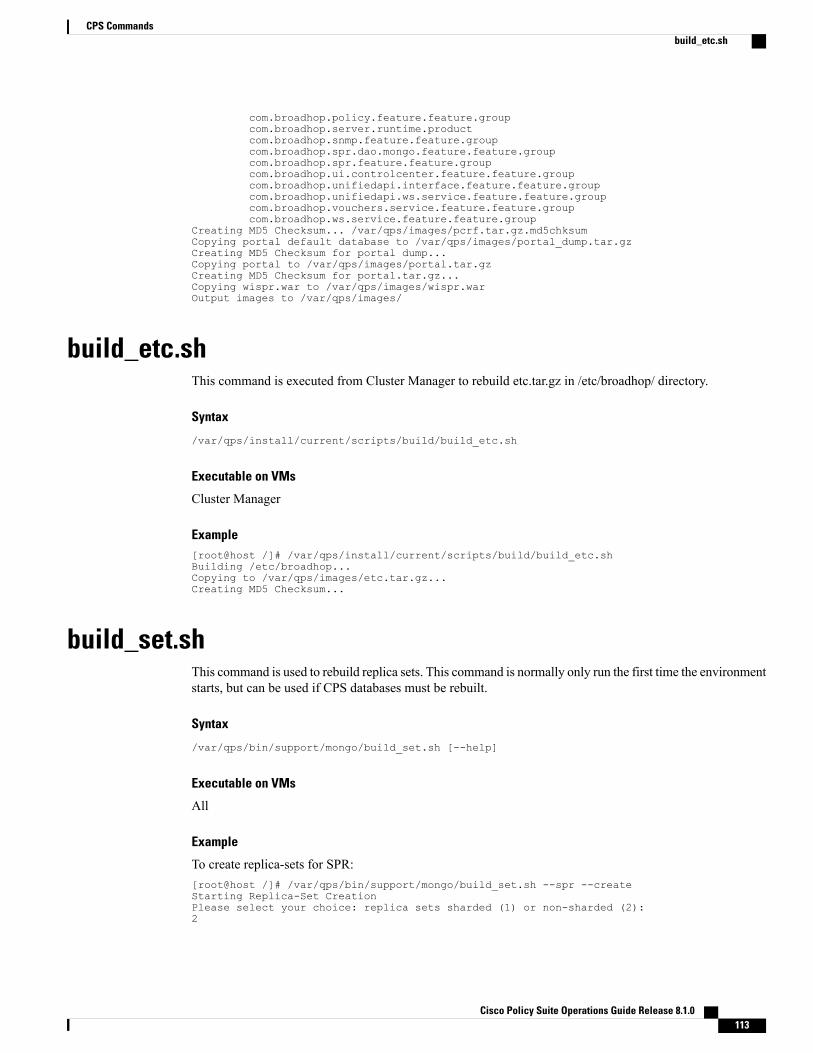
com.broadhop.policy.feature.feature.groupcom.broadhop.server.runtime.productcom.broadhop.snmp.feature.feature.groupcom.broadhop.spr.dao.mongo.feature.feature.groupcom.broadhop.spr.feature.feature.groupcom.broadhop.ui.controlcenter.feature.feature.groupcom.broadhop.unifiedapi.interface.feature.feature.groupcom.broadhop.unifiedapi.ws.service.feature.feature.groupcom.broadhop.vouchers.service.feature.feature.groupcom.broadhop.ws.service.feature.feature.group
Creating MD5 Checksum... /var/qps/images/pcrf.tar.gz.md5chksumCopying portal default database to /var/qps/images/portal_dump.tar.gzCreating MD5 Checksum for portal dump...Copying portal to /var/qps/images/portal.tar.gzCreating MD5 Checksum for portal.tar.gz...Copying wispr.war to /var/qps/images/wispr.warOutput images to /var/qps/images/
build_etc.shThis command is executed from Cluster Manager to rebuild etc.tar.gz in /etc/broadhop/ directory.
Syntax
/var/qps/install/current/scripts/build/build_etc.sh
Executable on VMs
Cluster Manager
Example[root@host /]# /var/qps/install/current/scripts/build/build_etc.shBuilding /etc/broadhop...Copying to /var/qps/images/etc.tar.gz...Creating MD5 Checksum...
build_set.shThis command is used to rebuild replica sets. This command is normally only run the first time the environmentstarts, but can be used if CPS databases must be rebuilt.
Syntax
/var/qps/bin/support/mongo/build_set.sh [--help]
Executable on VMs
All
Example
To create replica-sets for SPR:[root@host /]# /var/qps/bin/support/mongo/build_set.sh --spr --createStarting Replica-Set CreationPlease select your choice: replica sets sharded (1) or non-sharded (2):2
Cisco Policy Suite Operations Guide Release 8.1.0 113
CPS Commandsbuild_etc.sh
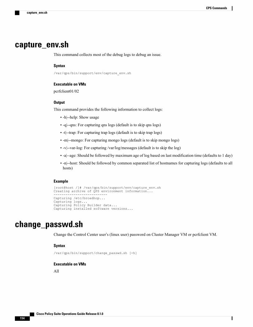
capture_env.shThis command collects most of the debug logs to debug an issue.
Syntax
/var/qps/bin/support/env/capture_env.sh
Executable on VMs
pcrfclient01/02
Output
This command provides the following information to collect logs:
• -h|--help: Show usage
• -q|--qns: For capturing qns logs (default is to skip qns logs)
• -t|--trap: For capturing trap logs (default is to skip trap logs)
• -m|--mongo: For capturing mongo logs (default is to skip mongo logs)
• -v|--var-log: For capturing /var/log/messages (default is to skip the log)
• -a|--age: Should be followed by maximum age of log based on last modification time (defaults to 1 day)
• -n|--host: Should be followed by common separated list of hostnames for capturing logs (defaults to allhosts)
Example[root@host /]# /var/qps/bin/support/env/capture_env.shCreating archive of QPS environment information...---------------------------Capturing /etc/broadhop...Capturing logs...Capturing Policy Builder data...Capturing installed software versions...
change_passwd.shChange the Control Center user’s (linux user) password on Cluster Manager VM or pcrfclient VM.
Syntax
/var/qps/bin/support/change_passwd.sh [-h]
Executable on VMs
All
Cisco Policy Suite Operations Guide Release 8.1.0114
CPS Commandscapture_env.sh
ExampleEnter username whose password needs to be changed:Enter new password:Re-enter new password:
Done.Disconnecting from pcrfclient01... done.
cleanup_license.shCleans up the records related to license in the licensedfeats collection in the sharding DB. This commandmust be run as root user when license file is updated on pcrfclient machine.
Syntax
/var/qps/bin/support/mongo/cleanup_license.sh [-h]
Executable on VMs
• Cluster Manager
• pcrfclient01/02
copytoall.shPrior to 7.0.5 release, in order to propagate the changes done in Cluster Manager, user used to executereinit.sh which in turn triggers each CPS VM to download and install the updated VM images from theCluster Manager and it time consuming process.
In CPS 7.0.5 and higher releases, if minor changes are made to any file in ClusterManager, instead of executingreinit.sh script, use this command to synchronize the modified files from Cluster Manager to all other VMs.
Syntax
copytoall.sh
Executable on VMs
Cluster Manager
In case executing copytoall.sh command from qns-admin, prefix sudo before the command.Note
Example
1 If the user updated /etc/broadhop/logback.xml file in Cluster Manager.
2 Build etc directory on each cluster by executing build_all.sh from Cluster Manager to rebuild CPS packagescript./var/qps/install/current/scripts/build_all.sh
Cisco Policy Suite Operations Guide Release 8.1.0 115
CPS Commandscleanup_license.sh
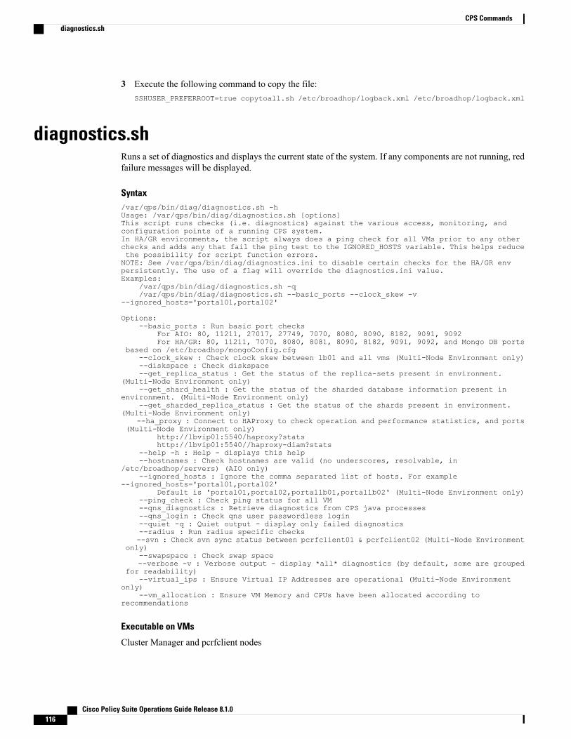
3 Execute the following command to copy the file:SSHUSER_PREFERROOT=true copytoall.sh /etc/broadhop/logback.xml /etc/broadhop/logback.xml
diagnostics.shRuns a set of diagnostics and displays the current state of the system. If any components are not running, redfailure messages will be displayed.
Syntax/var/qps/bin/diag/diagnostics.sh -hUsage: /var/qps/bin/diag/diagnostics.sh [options]This script runs checks (i.e. diagnostics) against the various access, monitoring, andconfiguration points of a running CPS system.In HA/GR environments, the script always does a ping check for all VMs prior to any otherchecks and adds any that fail the ping test to the IGNORED_HOSTS variable. This helps reducethe possibility for script function errors.NOTE: See /var/qps/bin/diag/diagnostics.ini to disable certain checks for the HA/GR envpersistently. The use of a flag will override the diagnostics.ini value.Examples:
/var/qps/bin/diag/diagnostics.sh -q/var/qps/bin/diag/diagnostics.sh --basic_ports --clock_skew -v
--ignored_hosts='portal01,portal02'
Options:--basic_ports : Run basic port checks
For AIO: 80, 11211, 27017, 27749, 7070, 8080, 8090, 8182, 9091, 9092For HA/GR: 80, 11211, 7070, 8080, 8081, 8090, 8182, 9091, 9092, and Mongo DB ports
based on /etc/broadhop/mongoConfig.cfg--clock_skew : Check clock skew between lb01 and all vms (Multi-Node Environment only)--diskspace : Check diskspace--get_replica_status : Get the status of the replica-sets present in environment.
(Multi-Node Environment only)--get_shard_health : Get the status of the sharded database information present in
environment. (Multi-Node Environment only)--get_sharded_replica_status : Get the status of the shards present in environment.
(Multi-Node Environment only)--ha_proxy : Connect to HAProxy to check operation and performance statistics, and ports
(Multi-Node Environment only)http://lbvip01:5540/haproxy?statshttp://lbvip01:5540//haproxy-diam?stats
--help -h : Help - displays this help--hostnames : Check hostnames are valid (no underscores, resolvable, in
/etc/broadhop/servers) (AIO only)--ignored_hosts : Ignore the comma separated list of hosts. For example
--ignored_hosts='portal01,portal02'Default is 'portal01,portal02,portallb01,portallb02' (Multi-Node Environment only)
--ping_check : Check ping status for all VM--qns_diagnostics : Retrieve diagnostics from CPS java processes--qns_login : Check qns user passwordless login--quiet -q : Quiet output - display only failed diagnostics--radius : Run radius specific checks--svn : Check svn sync status between pcrfclient01 & pcrfclient02 (Multi-Node Environment
only)--swapspace : Check swap space--verbose -v : Verbose output - display *all* diagnostics (by default, some are grouped
for readability)--virtual_ips : Ensure Virtual IP Addresses are operational (Multi-Node Environment
only)--vm_allocation : Ensure VM Memory and CPUs have been allocated according to
recommendations
Executable on VMs
Cluster Manager and pcrfclient nodes
Cisco Policy Suite Operations Guide Release 8.1.0116
CPS Commandsdiagnostics.sh

Example[root@pcrfclient01 ~]# diagnostics.shQNS DiagnosticsChecking basic ports (80, 7070, 27017, 27717-27720, 27749, 8080, 9091)...[PASS]Checking qns passwordless logins on all boxes...[PASS]Validating hostnames...[PASS]Checking disk space for all VMs...[PASS]Checking swap space for all VMs...[PASS]Checking for clock skew...[PASS]Retrieving QNS diagnostics from qns01:9045...[PASS]Retrieving QNS diagnostics from qns02:9045...[PASS]Checking HAProxy status...[PASS]Checking VM CPU and memory allocation for all VMs...[PASS]Checking Virtual IPs are up...[PASS][root@pcrfclient01 ~]#
list_installed_features.shDisplays the features and versions of the features that are installed on each VM in the environment.
Syntax
/var/qps/bin/diag/list_installed_features.sh
Executable on VMs
All
Example[root@host /]# /var/qps/bin/diag/list_installed_features.shFeatures installed on lb01:9045com.broadhop.infrastructure.feature=7.0.2.r072627com.broadhop.iomanager.feature=7.0.2.r072627com.broadhop.server.runtime.product=7.0.2.r072627com.broadhop.snmp.feature=7.0.2.r072627Features installed on lb02:9045com.broadhop.infrastructure.feature=7.0.2.r072627com.broadhop.iomanager.feature=7.0.2.r072627com.broadhop.server.runtime.product=7.0.2.r072627com.broadhop.snmp.feature=7.0.2.r072627Features installed on qns01:9045com.broadhop.balance.service.feature=3.4.2.r071203com.broadhop.balance.spr.feature=3.4.2.r071203com.broadhop.custrefdata.service.feature=2.4.2.r072158com.broadhop.diameter2.local.feature=3.4.2.r072694com.broadhop.externaldatacache.memcache.feature=7.0.2.r072627com.broadhop.infrastructure.feature=7.0.2.r072627com.broadhop.policy.feature=7.0.2.r072627com.broadhop.server.runtime.product=7.0.2.r072627com.broadhop.snmp.feature=7.0.2.r072627com.broadhop.spr.dao.mongo.feature=2.3.2.r071887com.broadhop.spr.feature=2.3.2.r071887com.broadhop.ui.controlcenter.feature=3.4.2.r070445com.broadhop.unifiedapi.interface.feature=2.3.2.r072695com.broadhop.unifiedapi.ws.service.feature=2.3.2.r072695com.broadhop.vouchers.service.feature=3.4.2.r071203com.broadhop.ws.service.feature=1.5.2.r071537Features installed on qns02:9045com.broadhop.balance.service.feature=3.4.2.r071203com.broadhop.balance.spr.feature=3.4.2.r071203com.broadhop.custrefdata.service.feature=2.4.2.r072158com.broadhop.diameter2.local.feature=3.4.2.r072694com.broadhop.externaldatacache.memcache.feature=7.0.2.r072627com.broadhop.infrastructure.feature=7.0.2.r072627
Cisco Policy Suite Operations Guide Release 8.1.0 117
CPS Commandslist_installed_features.sh

com.broadhop.policy.feature=7.0.2.r072627com.broadhop.server.runtime.product=7.0.2.r072627com.broadhop.snmp.feature=7.0.2.r072627com.broadhop.spr.dao.mongo.feature=2.3.2.r071887com.broadhop.spr.feature=2.3.2.r071887com.broadhop.ui.controlcenter.feature=3.4.2.r070445com.broadhop.unifiedapi.interface.feature=2.3.2.r072695com.broadhop.unifiedapi.ws.service.feature=2.3.2.r072695com.broadhop.vouchers.service.feature=3.4.2.r071203com.broadhop.ws.service.feature=1.5.2.r071537Features installed on qns03:9045com.broadhop.balance.service.feature=3.4.2.r071203com.broadhop.balance.spr.feature=3.4.2.r071203com.broadhop.custrefdata.service.feature=2.4.2.r072158com.broadhop.diameter2.local.feature=3.4.2.r072694com.broadhop.externaldatacache.memcache.feature=7.0.2.r072627com.broadhop.infrastructure.feature=7.0.2.r072627com.broadhop.policy.feature=7.0.2.r072627com.broadhop.server.runtime.product=7.0.2.r072627com.broadhop.snmp.feature=7.0.2.r072627com.broadhop.spr.dao.mongo.feature=2.3.2.r071887com.broadhop.spr.feature=2.3.2.r071887com.broadhop.ui.controlcenter.feature=3.4.2.r070445com.broadhop.unifiedapi.interface.feature=2.3.2.r072695com.broadhop.unifiedapi.ws.service.feature=2.3.2.r072695com.broadhop.vouchers.service.feature=3.4.2.r071203com.broadhop.ws.service.feature=1.5.2.r071537Features installed on qns04:9045com.broadhop.balance.service.feature=3.4.2.r071203com.broadhop.balance.spr.feature=3.4.2.r071203com.broadhop.custrefdata.service.feature=2.4.2.r072158com.broadhop.diameter2.local.feature=3.4.2.r072694com.broadhop.externaldatacache.memcache.feature=7.0.2.r072627com.broadhop.infrastructure.feature=7.0.2.r072627com.broadhop.policy.feature=7.0.2.r072627com.broadhop.server.runtime.product=7.0.2.r072627com.broadhop.snmp.feature=7.0.2.r072627com.broadhop.spr.dao.mongo.feature=2.3.2.r071887com.broadhop.spr.feature=2.3.2.r071887com.broadhop.ui.controlcenter.feature=3.4.2.r070445com.broadhop.unifiedapi.interface.feature=2.3.2.r072695com.broadhop.unifiedapi.ws.service.feature=2.3.2.r072695com.broadhop.vouchers.service.feature=3.4.2.r071203com.broadhop.ws.service.feature=1.5.2.r071537Features installed on pcrfclient01:9045com.broadhop.controlcenter.feature=7.0.2.r072627com.broadhop.faultmanagement.service.feature=1.0.2.r071534com.broadhop.infrastructure.feature=7.0.2.r072627com.broadhop.server.runtime.product=7.0.2.r072627com.broadhop.snmp.feature=7.0.2.r072627Features installed on pcrfclient02:9045com.broadhop.controlcenter.feature=7.0.2.r072627com.broadhop.faultmanagement.service.feature=1.0.2.r071534com.broadhop.infrastructure.feature=7.0.2.r072627com.broadhop.server.runtime.product=7.0.2.r072627com.broadhop.snmp.feature=7.0.2.r072627Features installed on all (combined)com.broadhop.balance.service.feature=3.4.2.r071203com.broadhop.balance.spr.feature=3.4.2.r071203com.broadhop.controlcenter.feature=7.0.2.r072627com.broadhop.custrefdata.service.feature=2.4.2.r072158com.broadhop.diameter2.local.feature=3.4.2.r072694com.broadhop.externaldatacache.memcache.feature=7.0.2.r072627com.broadhop.faultmanagement.service.feature=1.0.2.r071534com.broadhop.infrastructure.feature=7.0.2.r072627com.broadhop.iomanager.feature=7.0.2.r072627com.broadhop.policy.feature=7.0.2.r072627com.broadhop.server.runtime.product=7.0.2.r072627com.broadhop.snmp.feature=7.0.2.r072627com.broadhop.spr.dao.mongo.feature=2.3.2.r071887com.broadhop.spr.feature=2.3.2.r071887com.broadhop.ui.controlcenter.feature=3.4.2.r070445com.broadhop.unifiedapi.interface.feature=2.3.2.r072695
Cisco Policy Suite Operations Guide Release 8.1.0118
CPS Commandslist_installed_features.sh

com.broadhop.unifiedapi.ws.service.feature=2.3.2.r072695com.broadhop.vouchers.service.feature=3.4.2.r071203com.broadhop.ws.service.feature=1.5.2.r071537
reinit.shThis command is executed from Cluster Manager. It SSHs to all the CPS VMs and triggers the/etc/init.d/vm-init.sh script on each VM to download all the puppet scripts, CPS softwares, /etc/hostsfiles and updates the VM with the new software from Cluster Manager to the VM.
Refer to vm-init.sh, on page 131, to trigger this process for a single VM as opposed to all VMs.
Syntax
/var/qps/install/current/scripts/upgrade/reinit.sh
Executable on VMs
Cluster Manager
Example[root@host /]# /var/qps/install/current/scripts/upgrade/reinit.shRunning pupdate on labUpdating /etc/hosts file from installer VM...Updating /etc/facter/facts.d/bxb1-lb01...Updating /etc/puppet from installer VM...
restartall.shThis command is executed from Cluster Manager. It stops and restarts all of the qns services on all VMs inthe CPS cluster. This command is also executed when new software is installed on VMs.
Refer restartqns.sh, on page 120 to restart qns services on a specific VM as opposed to all VMs.
Syntax
/var/qps/bin/control/restartall.sh
Executable on VMs
Cluster Manager
When executing restartall.sh command from qns-admin, prefix sudo before the command.Note
Example/var/qps/bin/control/restartall.shCurrently active LB: lb01
This process will restart all QPS software on the nodes in this order:
lb02 pcrfclient02 qns01 qns02 pcrfclient01 lb01
Cisco Policy Suite Operations Guide Release 8.1.0 119
CPS Commandsreinit.sh

restartqns.shThis command stops and restarts all qns services on the target VM.
Syntax
/var/qps/bin/control/restartqns.sh hostname
Executable on VMs
Cluster Manager
When executing restartqns.sh command from qns-admin, prefix sudo before the command.Note
Example/var/qps/bin/control/restartqns.sh qns01/var/qps/bin/control/restartqns.sh pcrfclient01
runonall.shExecutes a command, as provided as an argument, on all of the VMs listed in the servers file. These commandsmust be run as the CPS user on the remote VMs, or they will fail to execute properly.
Syntax
/opt/broadhop/control/runonall.sh <executable command>
Executable on VMs
All
In case executing runonall.sh command from qns-admin, prefix sudo before the command.Note
Example
/opt/broadhop/control/runonall.sh ntpdate -u
serviceThis command is used to control individual services on each VM.
Syntax
service < option > | --status-all | [ service_name [ command | --full-restart ] ]
Cisco Policy Suite Operations Guide Release 8.1.0120
CPS Commandsrestartqns.sh

Do not use this command for any services managed by themonit service. Use themonit summary commandto view the list of services managed by monit. The list of services managed by monit is different on eachCPS VM.
Caution
session_cache_ops.shThis command provides information about, and performs operations on the session database.
Syntax/var/qps/bin/support/mongo/session_cache_ops.sh <Argument1> <Argument2><Argument1>: --count or --remove--count--remove--statistics-count--add-shard<Argument2>: site1 or site2 or site3 ... sitenThis argument for GR only, in GR setup user need to pass the site number (site1 or site2...) as second argument
Options
--count
This option prints the count of sessions present in all available session_cache* databases.
The session count is the number of allocated entries in the database for unique subscriber sessions on thenetwork. Each allocated entry may have related nested sub-sessions with other session types such as Sy/Rx.
• A session count is incremented when a Gx CCR-i arrives and an entry (Mongo data structure called adocument) is allocated.
• If there are other types of sessions related to that unique subscriber during the life of the Gx session (orSy/Rx) these are nested within the "document".
• If these "other" types of sessions are terminated, they are removed from the document and those countertypes are decremented immediately.
•When the Gx CCR-t arrives it is decremented immediately from the Gx Type count.
• Up to 30 seconds later the unique session entry/document is removed, and the Session Total count isdecremented.
The other session types should not be used in validating the number of total sessions as this varies greatlybetween call models and time. These are simply specific totals drawn from each entry.
It is typical for the session_total_count will be slightly more than the Gx_TYPE count due to the 30 seconddelay. The reason for this delay is that the entry (document) needs to wait for any other related (nested) sessionsto close.
Cisco Policy Suite Operations Guide Release 8.1.0 121
CPS Commandssession_cache_ops.sh

On occasion there may be small variance of data between what the pcrfclient01 and pcrfclient02 report,although they are querying the same database. These are however comparable.
The counters processing order is that the total session count is performed first and the detailed session (types)are done second. Slight discrepancies/variance in the numbers may occur.
Example# session_cache_ops.sh --countSession cache operation scriptTue Dec 22 02:26:49 MST 2015------------------------------------------------------Session Replica-set SESSION-SET1------------------------------------------------------Session Database : Session Count------------------------------------------------------session_cache : 14session_cache_2 : 15session_cache_3 : 12session_cache_4 : 10------------------------------------------------------No of Sessions in SET1 : 51------------------------------------------------------Total Number of Sessions : 51
--remove
This option removes sessions from all available session_cache* databases.
You will be prompted to confirm this action after running this command. If you proceed, this will removeexisting sessions in the replica-set.
Example# session_cache_ops.sh --removeSession cache operation scriptTue Dec 22 02:29:42 MST 2015---------------------------------------------------------Session Replica-set SESSION-SET1---------------------------------------------------------WARNING: Continuing will remove existing sessions in
replica-set : SESSION-SET1CAUTION: This result into loss of session dataAre you sure you want to continue (y/yes or n/no)? : yRemoving sessions from session_cache dbconnecting to: sessionmgr04:27717/session_cacheWriteResult({ "nRemoved" : 1 })Remove sessions operation completed on session_cache db.Removing sessions from session_cache_2 dbconnecting to: sessionmgr04:27717/session_cache_2WriteResult({ "nRemoved" : 0 })Remove sessions operation completed on session_cache_2 db.Removing sessions from session_cache_3 dbconnecting to: sessionmgr04:27717/session_cache_3WriteResult({ "nRemoved" : 0 })Remove sessions operation completed on session_cache_3 db.Removing sessions from session_cache_4 dbconnecting to: sessionmgr04:27717/session_cache_4WriteResult({ "nRemoved" : 0 })Remove sessions operation completed on session_cache_4 db.---------------------------------------------------------
--statistics-count
This option prints statistics count of the sessions (types if the session Gx,Rx,… etc) in all availablesession_cache* databases.
Cisco Policy Suite Operations Guide Release 8.1.0122
CPS CommandsOptions

Example# session_cache_ops.sh --statistics-countSession cache operation scriptTue Dec 22 02:28:38 MST 2015------------------------------------------------------Sessions statistic counter on Genaral------------------------------------------------------Session Type : Session Count
------------------------------------------------------ADMIN-SET1EDR : 5GX_SCE : 10
------------------------------------------------------
--add-shard
Adds session shards to the session database, either normal shards or hot standby shards.
Example# session_cache_ops.sh --add-shardSession cache operation scriptTue Dec 22 02:22:24 MST 2015
Session Sharding--------------------------------------------------------
Select type of session shard Default [*]Hot Standby [ ]
Sessionmgr pairs : sessionmgr01:sessionmgr02:27717
Session shards per pair : 4
Creating Session sharding [ Done ]
--------------------------------------------------------Note :- Press 'y' to select the shard type- If sharding needed for multiple sessionmgr vms with portplease provide sessionmge vm with port separated by ':',and pair separated by ','
(Ex: sessionmgr01:sessionmgr02:27717,sessionmgr03:sessionmgr04:27717)
Executable on VMspcrfclient01/02
startall.shThis command is executed from Cluster Manager. It starts all qns services on all VMs in the CPS cluster.This command is also executed when a new software is installed on VMs.
Refer to startqns.sh, on page 124 to start services on a specific VM as opposed to all VMs.
Syntax
/var/qps/bin/control/startall.sh
Cisco Policy Suite Operations Guide Release 8.1.0 123
CPS CommandsExecutable on VMs
When executing startall.sh command from qns-admin, prefix sudo before the command.Note
Executable on VMs
Cluster Manager
Example
/var/qps/bin/control/startall.sh
startqns.shThis command is executed from Cluster Manager. It starts all qns services on the specified VM.
Syntax
/var/qps/bin/control/startqns.sh hostname
When executing startqns.sh command from qns-admin, prefix sudo before the command.Note
Executable on VMs
Cluster Manager
Example/var/qps/bin/control/startqns.sh qns01/var/qps/bin/control/startqns.sh pcrfclient01
statusall.shThis command displays whether the services managed by monit are stopped or running on all VMs. Thisscript can be executed from Cluster Manager or pcrfclient.
Syntax
/var/qps/bin/control/statusall.sh
When executing statusall.sh command from qns-admin, prefix sudo before the command.Note
Executable on VMs
• Cluster Manager
• pcrfclient01/02
Cisco Policy Suite Operations Guide Release 8.1.0124
CPS Commandsstartqns.sh

Output
For each process or program, the command displays:
• Status
◦Running – the process/Program is healthy and running
◦Does not exist – the process id specified in the /var/run/processname-pid does not exist. This is acause for concern if recurring.
◦Waiting – This is normal for a program /process monitored by monit
◦Status ok – This is normal for a program monitored by monit
•Monitoring Status
◦Monitored – The process/program is being monitored
◦Not Monitored – The process/program is not under the control of monit
◦Waiting –A transient state which reports as waiting depending upon when the statusall.sh commandis run which internally uses monit status command.
For more details, see: https://bitbucket.org/tildeslash/monit/issue/114/.Note
• UptimeThe number of days, hours, and minutes the process or program has been running.
Example[root@host /]# /var/qps/bin/control/statusall.shExecuting 'sudo /usr/bin/monit status' on all QNS ServersThe Monit daemon 5.5 uptime: 2h 12mProcess 'snmptrapd'status Runningmonitoring status Monitoreduptime 15h 33m
Process 'snmpd'status Runningmonitoring status Monitoreduptime 2h 12m
Process 'sessionmgr-27017'status Runningmonitoring status Monitoreduptime 15h 33m
Process 'qns-2'status Runningmonitoring status Monitoreduptime 15h 33m
Process 'qns-1'status Runningmonitoring status Monitoreduptime 15h 33m
Process 'memcached'status Runningmonitoring status Monitoreduptime 15h 33m
Process 'logstash'status Runningmonitoring status Monitoreduptime 15h 33m
Cisco Policy Suite Operations Guide Release 8.1.0 125
CPS Commandsstatusall.sh
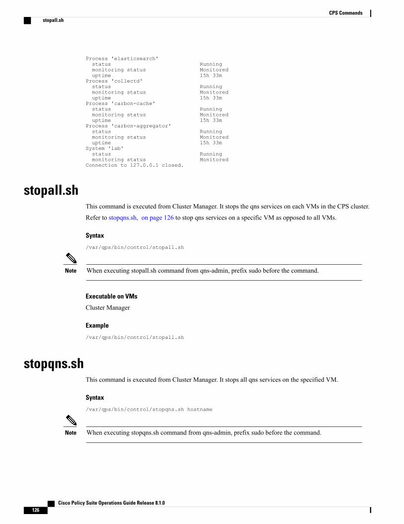
Process 'elasticsearch'status Runningmonitoring status Monitoreduptime 15h 33m
Process 'collectd'status Runningmonitoring status Monitoreduptime 15h 33m
Process 'carbon-cache'status Runningmonitoring status Monitoreduptime 15h 33m
Process 'carbon-aggregator'status Runningmonitoring status Monitoreduptime 15h 33m
System 'lab'status Runningmonitoring status Monitored
Connection to 127.0.0.1 closed.
stopall.shThis command is executed from Cluster Manager. It stops the qns services on each VMs in the CPS cluster.
Refer to stopqns.sh, on page 126 to stop qns services on a specific VM as opposed to all VMs.
Syntax
/var/qps/bin/control/stopall.sh
When executing stopall.sh command from qns-admin, prefix sudo before the command.Note
Executable on VMs
Cluster Manager
Example
/var/qps/bin/control/stopall.sh
stopqns.shThis command is executed from Cluster Manager. It stops all qns services on the specified VM.
Syntax
/var/qps/bin/control/stopqns.sh hostname
When executing stopqns.sh command from qns-admin, prefix sudo before the command.Note
Cisco Policy Suite Operations Guide Release 8.1.0126
CPS Commandsstopall.sh

Executable on VMs
Cluster Manager
Example
/var/qps/bin/control/stopqns.sh qns01
summaryall.shThis command provides a brief status of the services managed by monit on all VMs in the CPS cluster.
Syntax
/var/qps/bin/control/summaryall.sh
When executing summaryall.sh command from qns-admin, prefix sudo before the command.Note
Executable on VMs
Cluster Manager
Example[root@host /]# /var/qps/bin/control/summaryall.shExecuting 'sudo /usr/bin/monit summary' on all QNS ServersThe Monit daemon 5.5 uptime: 3d 19h 21m
Process 'snmptrapd' RunningProcess 'snmpd' RunningProgram 'vip_trap' Status okProcess 'qns-4' RunningProcess 'qns-3' RunningProcess 'qns-2' RunningProcess 'qns-1' RunningProcess 'memcached' RunningProcess 'haproxy-diameter' RunningProcess 'haproxy' RunningProcess 'corosync' RunningProgram 'cpu_load_monitor' Status okProgram 'cpu_load_trap' Status okProcess 'collectd' RunningSystem 'lb01' RunningThe Monit daemon 5.5 uptime: 4d 23h 50m
Process 'snmptrapd' RunningProcess 'snmpd' RunningProgram 'vip_trap' Status okProcess 'qns-4' RunningProcess 'qns-3' RunningProcess 'qns-2' RunningProcess 'qns-1' RunningProcess 'memcached' RunningProcess 'haproxy-diameter' RunningProcess 'haproxy' RunningProcess 'corosync' RunningProgram 'cpu_load_monitor' Status okProgram 'cpu_load_trap' Status okProcess 'collectd' RunningSystem 'lb02' RunningThe Monit daemon 5.5 uptime: 11d 23h 25m
Cisco Policy Suite Operations Guide Release 8.1.0 127
CPS Commandssummaryall.sh

Process 'snmpd' RunningProcess 'memcached' RunningProgram 'cpu_load_monitor' Status okProgram 'cpu_load_trap' WaitingProcess 'collectd' RunningSystem 'sessionmgr01' RunningThe Monit daemon 5.5 uptime: 4d 23h 48m
Process 'snmpd' RunningProcess 'memcached' RunningProgram 'cpu_load_monitor' Status okProgram 'cpu_load_trap' WaitingProcess 'collectd' RunningSystem 'sessionmgr02' RunningThe Monit daemon 5.5 uptime: 5d 2h 18m
Process 'snmpd' RunningProcess 'qns-1' WaitingProgram 'cpu_load_monitor' Status okProgram 'cpu_load_trap' WaitingProcess 'collectd' RunningSystem 'qns01' RunningThe Monit daemon 5.5 uptime: 4d 23h 22m
Process 'snmpd' RunningProcess 'qns-1' WaitingProgram 'cpu_load_monitor' Status okProgram 'cpu_load_trap' WaitingProcess 'collectd' RunningSystem 'qns02' RunningThe Monit daemon 5.5 uptime: 5d 23h 14m
Process 'snmpd' RunningProgram 'db_trap' WaitingProgram 'failover_trap' WaitingProgram 'qps_process_trap' WaitingProgram 'admin_login_trap' WaitingProgram 'vm_trap' WaitingProgram 'gr_site_status_trap' WaitingProgram 'qps_message_trap' WaitingProcess 'qns-2' RunningProcess 'qns-1' RunningProgram 'monitor_replica' WaitingProcess 'logstash' RunningProcess 'elasticsearch' RunningProgram 'cpu_load_monitor' Status okProgram 'cpu_load_trap' WaitingProcess 'collectd' RunningProcess 'carbon-cache' RunningProcess 'carbon-aggregator' RunningSystem 'pcrfclient01' RunningThe Monit daemon 5.5 uptime: 4d 23h 52m
Process 'snmpd' RunningProgram 'db_trap' WaitingProgram 'failover_trap' WaitingProgram 'qps_process_trap' WaitingProgram 'admin_login_trap' WaitingProgram 'vm_trap' WaitingProgram 'gr_site_status_trap' WaitingProgram 'qps_message_trap' WaitingProcess 'qns-2' WaitingProcess 'qns-1' WaitingProgram 'monitor_replica' WaitingProcess 'logstash' RunningProcess 'elasticsearch' RunningProgram 'cpu_load_monitor' Status okProgram 'cpu_load_trap' WaitingProcess 'collectd' RunningProcess 'carbon-cache' RunningProcess 'carbon-aggregator' RunningSystem 'pcrfclient02' Running
Cisco Policy Suite Operations Guide Release 8.1.0128
CPS Commandssummaryall.sh
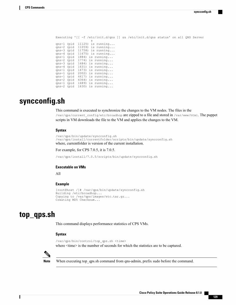
Executing '[[ -f /etc/init.d/qns ]] && /etc/init.d/qns status' on all QNS Servers
qns-1 (pid 11125) is running...qns-2 (pid 11059) is running...qns-3 (pid 11758) is running...qns-4 (pid 11675) is running...qns-1 (pid 1884) is running...qns-2 (pid 1774) is running...qns-3 (pid 1684) is running...qns-4 (pid 1631) is running...qns-1 (pid 1473) is running...qns-1 (pid 2002) is running...qns-1 (pid 4417) is running...qns-2 (pid 4364) is running...qns-1 (pid 1689) is running...qns-2 (pid 1630) is running...
syncconfig.shThis command is executed to synchronize the changes to the VM nodes. The files in the/var/qps/current_config/etc/broadhop are zipped to a file and stored in /var/www/html. The puppetscripts in VM downloads the file to the VM and applies the changes to the VM.
Syntax/var/qps/bin/update/syncconfig.sh/var/qps/install/currentfolder/scripts/bin/update/syncconfig.shwhere, currentfolder is version of the current installation.
For example, for CPS 7.0.5, it is 7.0.5.
/var/qps/install/7.0.5/scripts/bin/update/syncconfig.sh
Executable on VMs
All
Example[root@host /]# /var/qps/bin/update/syncconfig.shBuilding /etc/broadhop...Copying to /var/qps/images/etc.tar.gz...Creating MD5 Checksum...
top_qps.shThis command displays performance statistics of CPS VMs.
Syntax
/var/qps/bin/control/top_qps.sh <time>
where <time> is the number of seconds for which the statistics are to be captured.
When executing top_qps.sh command from qns-admin, prefix sudo before the command.Note
Cisco Policy Suite Operations Guide Release 8.1.0 129
CPS Commandssyncconfig.sh
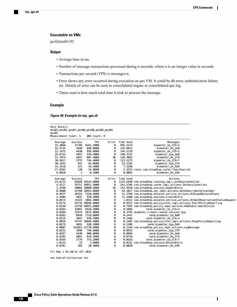
Executable on VMs
pcrfclient01/02
Output
• Average time in ms.
• Number of message transactions processed during n seconds, where n is an integer value in seconds.
• Transactions per second (TPS) is messages/n.
• Error shows any error occurred during execution on qns VM. It could be db error, authentication failureetc. Details of error can be seen in consolidated engine or consolidated qns log.
• Times used is how much total time it took to process the message.
Example
Figure 36: Example for top_qps.sh
Cisco Policy Suite Operations Guide Release 8.1.0130
CPS Commandstop_qps.sh
Diameter Synchronization Message BehaviorSome diameter messages (like UDR) are synchronous diameter calls that means qns will be waiting forresponse after sending diameter request.
Response of these diameter message is not captured in top_qps as those message are not processed in policyengine separately.
Average time 3.3676 shown below is round trip time (from UDR sent to UDA received)
Sample Top_Qns--------------------------------------------------------------------------------------------
Average Success TPS Error Time Used Messages9.7211 2910 727.5000 0 28.2883 diameter_Gx_CCR-I
--------------------------------------------------------------------------------------------
Average Success TPS Error Time Used Actions3.6854 2924 731.0000 0 10.7761
com.broadhop.cache.impl.actions.GetSessionAction3.3676 2922 730.5000 0 9.8400 send.sync.diameter_Sh_UDR0.7908 2919 729.7500 0 2.3083 com.broadhop.session.CreateEntry0.1981 2924 731.0000 0 0.5793
com.broadhop.locking.impl.LockSessionAction0.0480 2919 729.7500 0 0.1400 send.diameter_Gx_CCA-I0.0126 2924 731.0000 0 0.0370 diameter.create.remote.session.Sh
Average time is not applicable for these response messages. However, number of response messages (UDA)received can be seen from Grafana.
vm-init.shThis command is executed from the VM nodes from /etc/init.d, (starts up automatically if VM rebootstoo). It downloads all the puppet script, CPS software, /etc/hosts files and updates the VM with the newsoftware.
This command only updates the software and does not restart the CPS software. The new software will berun only after process restart (for example, by executing /var/qps/bin/control/restartall.sh script fromCluster Manager).
Syntax
/etc/init.d/vm-init.sh
Executable on VMs
Any CPS VM
Example
/etc/init.d/vm-init.sh
Cisco Policy Suite Operations Guide Release 8.1.0 131
CPS CommandsDiameter Synchronization Message Behavior

Cisco Policy Suite Operations Guide Release 8.1.0132
CPS Commandsvm-init.sh

Glossary
3G systems3G is the third generation of mobile phone standards and technology. It is based on the international Telecommunication Union (ITU)family of standards under the International Mobile Telecommunications Programme, MT-2000.
3GPPThird Generation Partnership Project
4G System4G is the fourth generation of cellular wireless standards, a successor to the 3G and 2G families of standards. In 2008, the ITU-Rorganization specified the IMT-Advanced (International Mobile Telecommunications Advanced) requirements for 4G standards,setting peak speed requirements for 4G service at 100 Mbit/s for high mobility communication (such as from trains and cars) and 1Gbit/s for low mobility communication (such as pedestrians and stationary users.
A
AAA/AARAuthorize/Authenticate-Request/Answer
ADCApplication Detection and Control
ADNApplication Delivery Network
Cisco Policy Suite Operations Guide Release 8.1.0 133

AFApplication FunctionElement offering application(s) that use IP bearer resources.
One example of an AF is the P-CSCF of the IM CN subsystem.Note
AF SessionApplication-level session established by an application-level signaling protocol offered by the AF that requires a session set-up withexplicit session description before the use of the service.
One example of an application session is an IMS session.Note
AN GatewayAccess Network Gateway
answer service templateA service template for Diameter; answering a request.
APIApplication Programming Interface
applicationA Diameter application that defines the data needed to perform various related actions.
Application Service ProviderA business entity responsible for the application that is being/will be used by a UE, which may be either an AF operator or has anassociation with the AF operator.
ARAC-FAccess Resource Admission Control Function
ARPAllocation and Retention Priority
Cisco Policy Suite Operations Guide Release 8.1.0134
GlossaryAF

ASACommand for an Abort Session Answer
ASPApplication Service Provider
ASRCommand for an Abort Session Request
authorised QoSThe maximum QoS that is authorized for a service data flow. In case of an aggregation of multiple service data flows within oneIP-CAN bearer (e.g. for GPRS a PDP context), the combination of the “Authorized QoS” information of the individual service dataflows is the “Authorized QoS” for the IP-CAN bearer. It contains the QoS class identifier and the data rate.
AVPAttribute Value PairSee RFC 3588 [5], corresponds to an Information Element in a Diameter message.
B
BBERFBearer Binding and Event Reporting Function
BBFBearer Binding Function
BGBorder Gateway
bindingPCRF process of associating IP flows described in AF Service Information with IP-CAN bearers. The association between a servicedata flow and the IP-CAN bearer (for GPRS the PDP context) transporting that service data flow.
binding mechanismThe method for creating, modifying and deleting bindings.
Cisco Policy Suite Operations Guide Release 8.1.0 135
GlossaryASA
blueprintPredefined packages of data (Policies, Reference Data, and so on) managed by Cisco Policy Builder 7.0 and used to start animplementation project quickly.
BNGBroadband Network Gateway
BSSBlock Started by Symbol/Business Support Systems
burstingSubscriber session where periods of rapid and high transmission spiking are followed by quiescent, silent, periods.
C
calculated session classA calculated session class stores attributes and recalculates them each time a policy references the calculated session objects. Acalculated session class sets its own data. It can calculate what a value should be and will evaluate that data whenever asked ratherthan waiting for other policies to set its information.
calculator decoratorA Calculator Decorator stores attributes that are recalculated each time the policies reference the calculator object. A CalculatedDecorator sets its own data. It can calculate what a value should be and will evaluate that data whenever asked, e.g.TimeSpentThisSession.
CAPEXCapacity Expansion/Capital Expense
CARCDR Analysis and Reporting from Cisco Systems
CCACredit Control Answer
CCRCredit Control Request
Cisco Policy Suite Operations Guide Release 8.1.0136
Glossaryblueprint

CDRCall Detail Record
charging controlThe process of associating packets, belonging to a service data flow, to a charging key and applying online charging and/or offlinecharging, as appropriate.
charging keyInformation used by the online and offline charging system for rating purposes.
childSome other subcomponent on the hierarchy tree, which occupies the left pane.
classIn object-oriented programming, a class is a construct that is used as a blueprint (or template) to create objects of that class. Thisblueprint describes the state and behavior that the objects of the class all share.An object of a given class is called an instance of the class. The class that contains that instance can be considered as the type of thatobject, e.g. a type of an object of the “Fruit” class would be “Apple”.
CLICommand Line Interface
CMSIn Subscriber Services Portal (SSP), this means ContentManagement System. The CMS helps the provider develop skins for subscriberpages.
CNRCisco Network Registrar from Cisco Systems
CoAChange of Authentication/Change of Authorization/Certificate of Authority
CoA shared secretA piece of data such as a password or pass phrase, known only by the entities involved in a secure communication for the purposesof authentication.
Cisco Policy Suite Operations Guide Release 8.1.0 137
GlossaryCDR

CODECCoder-decoder
condition phraseA Condition which can be used by a policy. For example, A user exists with name X.
configured blueprintAn implementation of a blueprint (either initial or and extension) to which configured extension points will be added.
configured extension pointA configured extension point provides a way to add policies to your Cisco Network Suite system, augmenting the standard policiesCisco Network Suite provides.
configured trigger extension pointConfigured trigger extension points let you specifically start and stop a session, based on criteria you specify.
COPSCommon Open Policy Service
COTSCommon Off-the-shelf
CPSCisco Policy Suite, Cisco Systems, Inc. collection of policy, PCRF, and PCEF software.
CRFCharging Rules Function
CSGClosed Subscriber Group
CSG IDClosed Subscriber Group Identity
Cisco Policy Suite Operations Guide Release 8.1.0138
GlossaryCODEC
D
DCCADiameter Credit-Control Application
decision tableA type of policy which can simplify the creation of similar policies using a table/spreadsheet format. For example, if username='A'then bandwidth='B' - Table (A,B): (jdoe, superhigh) (jdoe,superlow) (*, default)
DHCPDynamic Host Configuration Protocol, one of the protocols in the TCP/IP networking suite.
DiameterDiameter is a computer networking protocol for AAA (authentication, authorization and accounting). It is a successor to RADIUS.Diameter controls communication between the Secure Ticket Authority (STA) and any network entity requesting authentication.
DRADiameter Routing Agent
DRA bindingThe PCRF routing information stored per UE or per PDN in the DRA, which include the user identity (UE NAI), the UE IPv4 addressand/or IPv6 prefix, the APN (if available) and the selected PCRF identity for a certain IP-CAN Session.
DSLDigital Subscriber Line
DWR/DWADW Request/DW Acknowledgment
dynamic PCC RuleA PCC rule for which the definition is provided in the PCEF via the Gx reference point.
Cisco Policy Suite Operations Guide Release 8.1.0 139
GlossaryD

E
ECUREvent Charging with Unit Reservation
ESXiAn operating system from VMWare permitting placement of the hypervisor onto a dedicated compact storage device.
event reportA notification, possibly containing additional information of an event which occurs that corresponds with an event trigger. Also, anevent report is a report from the PCRF to the AF concerning transmission resources or requesting additional information.
event triggerA rule specifying the event reporting behavior of a PCEF or BBERF. Also, a trigger for credit management events.
extensionA software extension is a computer program designed to be incorporated into another piece of software in order to enhance, or extend,the functionalities of the latter. On its own, the program is not useful or functional.
extension blueprintA blueprint that depends on data from another blueprint.
extension pointAplace in a Cisco Systems blueprint which can be extendedwith additional policies and policy groups for a given client implementation.For example, Extension Point: 'Set User bandwidth' which would allow a client to add specific policies to set bandwidth.
F
FONFiber Optic Network
FTTxFiber To The Wherever
Cisco Policy Suite Operations Guide Release 8.1.0140
GlossaryE

G
Gateway Control SessionAn association between a BBERF and a Cisco Network Suite (when GTP is not used in the EPC), used for transferring access-specificparameters, BBERF events, and QoS rules between the Cisco Network Suite and BBERF. In the context of this specification, this isimplemented by use of the Gxx procedures.
gating controlThe process of blocking or allowing packets, belonging to a service data flow, to pass through to the desired endpoint.
GBRGuaranteed Bit Rate
GBR bearerAn IP-CAN bearer with reserved (guaranteed) bit rate resources.
GGSNGateway GPRS Support Node/Gateway General Support Node
GPRS IP-CANThis IP-CAN incorporates GPRS over GERAN and UTRAN, see TS 23.060 [12].
GPRS_Core_NetworkThe General Packet Radio Service (GPRS) system is used by GSM mobile phones, the most common mobile phone system in theworld, for transmitting IP packets. The GPRS core network is the centralized part of the GPRS system. It also provides support forWCDMA-based 3G networks. The GPRS core network is an integrated part of the GSM network switching subsystem.
group of applicationsIn usage monitoring, a set of ADC rules sharing a common monitoring key.
GSM - Groupe Spécial MobileGSM is a cellular network. Mobile phones connect to it by searching for cells in the immediate vicinity. GSM (Global System forMobile communications: originally from Groupe Spécial Mobile) is the most popular standard for mobile phones in the world.
GTPGPRS Tunneling Protocol
Cisco Policy Suite Operations Guide Release 8.1.0 141
GlossaryG

GxxGx extension
H
H-AFHome Application Function
H-DRAHome Diameter Routing Agent
H-PCEFA PCEF in the HPLMN
H-PCRFHome Policy Charging Rules Function
Home Routed AccessRoaming scenario where the PCEF is located in the HPLMN. In a Home Routed roaming scenario, the UE obtains access to thepacket data network from the HPLMN.
HPLMNHome Public Land Mobile Network
HRHome-Routed
HRPDHigh Rate Packet Data
HSGWHRPD Serving Gateway
HTTPHypertext Transfer Protocol
Cisco Policy Suite Operations Guide Release 8.1.0142
GlossaryGxx

I
I-WLAN IP-CANThis IP-CAN incorporates 3GPP IP access of I-WLAN, see TS 23.234 [13].
IMSA database system from IBM consisting of IMS/Data Base and IMS/Data Communications.
IMSIP Multimedia Subsystem, a set of specifications from 3GPP for delivering IP multimedia to mobile users.
initial blueprintA root-level blueprint. This type of blueprint does not depend on data from another blueprint to exist. The initial blueprint containsPolicy Groups, Policies and Extension Points relating to a given piece of functionality.
IP flowUnidirectional flow of IP packets with the same Source IP address and port number, Destination IP address and port number, Transportprotocol. Port numbers are only applicable if used by the transport protocol.
IP-CANIP connectivity Access NetworkAn IP transmission path of defined capacity, delay, and bit error rate.
IP-CAN bearerIP transmission path of defined capacity, delay and bit error rate, etc. See 3GPP TS 21.905 [1] for the definition of bearer.
IP-CAN sessionThe association between a UE and an IP network. The association is identified by one or more UE IP addresses (one IPv4 and/or oneIPv6 address) together with a UE identity information, if available, and a PDN represented by a PDN ID (e.g. an APN). An IP-CANsession incorporates one or more IP-CAN bearers. Support for multiple IP-CAN bearers per IP-CAN session is IP-CAN specific. AnIP-CAN session exists as long as the related UE IP addresses are assigned and announced to the IP network.
IPHKInternet Protocol Host Key
Cisco Policy Suite Operations Guide Release 8.1.0 143
GlossaryI

ISGIntelligent Services Gateway, a Cisco Systems policy enforcement point.
ISOAn ISO image (International Organization for Standardization) is an archive file (also known as a disc image) of an optical disc,composed of the data contents of every written sector of an optical disc, including the optical disc file system.
J
Java Action PhraseAn action a policy that is based on Java code.
JuniperJuniper Networks provides high-performance network infrastructure.
L
LDAPLightweight Directory Access Protocol/Lightweight Data Access Protocol
LocationIn Subscriber Services Portal (SSP) a location is the URL that a subscriber logs in to.
LTELong Term Evolution
M
MACA Media Access Control address (MAC address) is a unique identifier assigned to network interfaces for communications on thephysical network segment.
MBRMaximum Bit Rate
Cisco Policy Suite Operations Guide Release 8.1.0144
GlossaryISG
MMSCMultimedia Message Service Center
Monitoring keyInformation used by the PCEF and PCRF for usage monitoring control purposes as a reference to a given set of service data flowsthat all share a common allowed usage on a per UE and APN basis.
MPSMultimedia Priority Service
MPS sessionA session for which priority treatment is applied for allocating and maintaining radio and network resources to support theMultimediaPriority Service (MPS). MPS is defined in 3GPP TS 22.153 [31]
N
network session informationAll the information that Cisco Network Suite knows about a subscriber. The information is set by Policies.
NGNNext Generation Network
non-GBR bearerAn IP-CAN bearer with no reserved (guaranteed) bit rate resources.
O
object action phraseAn action a policy can use that is based on Session objects in the Policy Builder GUI.
OCSOnline Charging System
Cisco Policy Suite Operations Guide Release 8.1.0 145
GlossaryMMSC

OFCSOffline Charging System
operator-controlled serviceA service for which complete PCC rule information, including service data flow filter information, is available in the PCRF throughconfiguration and/or dynamic interaction with an AF.
OSSOpen Source Software
OVFOpen Virtualization Format
P
P-CSCFProxy-Call Session Control FunctionThe P-CSCF is the entry point to the IMS domain and serves as the outbound proxy server for the UE.
PAProxy Agent
packet flowA specific user data flow carried through the PCEF. A packet flow can be an IP flow.
PBHK - Port-bundle Host-keyThis provides an apparatus and method to associate a subscriber with one of many port bundles in an aggregation device. The methodreserves one of the port bundles for the subscriber if the subscriber was not assigned a port bundle, changes the original source portnumber in a data packet to a port bundle number, modifies the subscriber address to an assigned aggregation address, and issues arequest to a remote management device for authentication of the subscriber. Once a response is received from the management deviceincluding the authentication or unauthentication of the subscriber, the subscriber is mapped with the reserved port bundle in a portbundle object and the reserved port bundle is then assigned to the subscriber. The apparatus has at least one source port to receive adata packet, several port bundles coupled to the source port, each port bundle having a memory with a port bundle object to associatethe subscriber with one of the port bundles, a processor coupled to the port bundles, and an output port coupled to the processor.
PCCPolicy and Charging Control
Cisco Policy Suite Operations Guide Release 8.1.0146
GlossaryOFCS

PCC decisionA PCC decision consists of PCC rules and IP-CAN bearer attributes, which are provided by the PCRF to the PCEF for policy andcharging control.
PCC ruleA set of information enabling the detection of a service data flow and providing parameters for policy control and/or charging control.
PCRFPolicy and Charging Rules Function
PCEFPolicy and Charging Enforcement Function
PDFPolicy Decision Function
PDNPacket Data Network/Public Data Network/Process Data Network
PGWPDN-Gateway
PMEPolicy Management Engine
PMSPayment Management SystemAn electronic payment method such as PayPal.
policyThe policy is the building block of the Cisco Network Suite. A policy checks if a certain set of conditions is true and if so, executesactions. For example, if username='jdoe' then bandwidth='superhigh'.
policy controlThe process where the PCRF indicates to the PCEF how to control the IP-CAN bearer. Policy control includes QoS control or gatingcontrol or both.
Cisco Policy Suite Operations Guide Release 8.1.0 147
GlossaryPCC decision

policy counterA mechanism within the OCS to track spending applicable for a subscriber.
policy counter statusA label whose values are not standardized and that is associated with a policy counter's value relative to the spending limit(s) (thenumber of possible policy counter status values for a policy counter is one greater than the number of thresholds associated with thatpolicy counter, i.e policy counter status values describe the status around the thresholds). This is used to convey information relatingto subscriber spending from OCS to PCRF. Specific labels are configured jointly in OCS and PCRF.
PEP - Policy Enforcement PointPEP is a component of policy-based management. When a user tries to access a file or other resource on a computer network or serverthat uses policy-based access management, the PEP describes the user's attributes to other entities on the system. The PEP gives thePolicy Decision Point (PDP) the job of deciding whether or not to authorize the user based on the description of the user's attributes.Applicable policies are stored on the system and are analyzed by the PDP. The PDP makes it's decision and returns the decision. ThePEP lets the user know whether or not they have been authorized to access the requested resource.
policy groupA logical grouping of policies that will be evaluated at the same time.For example, Policy Group: 'Set User Bandwidths' could contain all policies which set bandwidth. They would all be re-evaluated ifsomething important to bandwidth changed.
Port-bundle Key LengthFor PBHK, the port bundle number:Includes a range of sequential port numbers starting with a base port number.
Is approximated by range of sequential port numbers=2port bundle length.
The port bundle length is an integer between 1 to 16.
predefined PCC ruleA PCC rule that has been provisioned directly into the PCEF by the operator.
publishRepresents sending the configuration data from the Cisco Policy Builder Client and 'publishing' it into the QNS environment.
Cisco Policy Suite Operations Guide Release 8.1.0148
Glossarypolicy counter
Q
QCIQoS Class Identifier. A scalar that is used as a reference to a specific packet forwarding behavior, for example, packet loss rate,packet delay budget, to be provided to an SDF.
QMEQuota Management Engine
QNSCisco Network Suite, Cisco Systems, Inc. collection of policy, PCRF, and PCEF software.
QoEQuality of Experience
QoSQuality of Service
QoS class identifier (QCI)A scalar used as a reference to a specific packet forwarding behavior (e.g. packet loss rate, packet delay budget) to be provided to aSDF. This may be implemented in the access network by the QCI referencing node specific parameters that control packet forwardingtreatment (e.g. scheduling weights, admission thresholds, queue management thresholds, link layer protocol configuration, etc.), thathave been pre-configured by the operator at a specific node(s) (e.g. eNodeB).
QoS ruleA set of information enabling the detection of a service data flow and defining its associated QoS parameters.
Query MapParameters that are passed during initial redirection to be saved in the subscriber's browser session and included in QNS API calls.
R
RAARe-Authenticate Answer
Cisco Policy Suite Operations Guide Release 8.1.0 149
GlossaryQ
RADIUSRemote Authentication Dial in User Service
RADIUS service templateA service template for RADIUS. This template can be either a request or answer.
RANRadio Access Network
RARRe-authorization Request
RCP versionQNS uses the R9 PCRF specification.R9 includes the Gx, Gy, Rx, Sp, Gxx, and S9 interfaces. The Gxx and S9 interfaces were new in R8 and are for roaming scenarios.The Cisco Systems, Inc. GA release is focusing on Rx, Gx, Gy, and Sp (where Sp is not defined by the specification).
RDBMSRelational Data Base Management System
RedbackRedback Networks Inc. provides networking solutions for IP-based services and communications. Redback products create solutionsthat address building a next generation network.
RedirectionRedirect the detected service traffic to an application server (e.g. redirect to a top-up / service provisioning page).
RepositoryA software repository is a storage location from which software packages may be retrieved and installed on a computer.In the case of Cisco Policy Suite, we store the configuration and use data in a repository and manage it with Subversion, a versioncontrol software.
Subversion maintains current and historical versions of the Cisco Policy Suite configuration and policy files. You may use your ownversion Subversion control software if you have it.
Response service templateA service template for Diameter used for answering a request.
Cisco Policy Suite Operations Guide Release 8.1.0150
GlossaryRADIUS

RFC - Request for CommentsOne of a series of numbered Internet informational documents and standards widely followed by commercial software and freewarein the Internet and Unix communities. Few RFCs are standards but all Internet standards are recorded in RFCs. Perhaps the singlemost influential RFC has been RFC 822, the Internet electronic mail format standard.
root configured blueprintIn Cisco Policy Builder, the Root Blueprint is the starting blueprint for a policy framework. In general, this is always the startingblueprint used when configuring the policies. When first installed, the root blueprint is selected and becomes known as the initialblueprint, which can then be added to or modified, leaving the root blueprint unchanged.
RTCPRTP Control Protocol
RTPReal-time Transport Protocol
S
S-GWServing Gateway
S5/S8 PMIPProxy Mobile IP
SandvineSandvine helps DSL, FTTx, cable, fixed wireless, andmobile operators understand network traffic, mitigate malicious traffic, managenetwork congestion, and deliver QoS-prioritized multimedia services.
SCURSession Charging with Unit Reservation
SDFService Data Flow
SDKSoftware Development Kit
Cisco Policy Suite Operations Guide Release 8.1.0 151
GlossaryRFC - Request for Comments

SDMSubscriber Data Management
ServiceAn individual service defined by VSAs within the VSA. Contained in a service bundle as an offering to a customer.
service bundleA group of services that are offered to customers in a specific service location.
service data flowAn aggregate set of packet flows that matches a service data flow template.
service data flow filterA set of packet flow header parameter values or ranges, used to identify one or more of the packet flows constituting a service dataflow.
service data flow filter identifierA scalar that is unique for a specific service data flow (SDF) filter (used on Gx and Gxx) within an IP-CAN session.
service data flow templateThe set of service data flow filters in a PCC rule, required for defining a service data flow.
service identifierAn identifier for a service. The service identifier provides the most detailed identification, specified for flow based charging, of aservice data flow. A concrete instance of a service may be identified if additional AF information is available (further details to befound in clause 6.3.1).
service informationSet of information conveyed from the AF to the Cisco Network Suite over the Rx interface, to be used as a basis for PCC decisionsat the Cisco Network Suite, including information about the AF session (e.g. application identifier, type of media, bandwidth, IPaddress and port number).
service managementThe integrated set of functions that together enable a service provider to effectively define, deploy and manage advanced multi-serviceofferings on their packet-based network. Key elements include: identification and authentication, subscriber service profile management,service and policy management, dynamic service portal, billing and payments. These functions form the critical service managementlayer in the IMS framework, linking network applications with network infrastructure and control.
Cisco Policy Suite Operations Guide Release 8.1.0152
GlossarySDM

service templateA template that defines what data needs to be sent for a given service.Service construct that contains the basic VSAs required to create a service. Additional information, such as access policies, billingrules and pricing are applied to a service template to create a specific service.
session based serviceAn end user service requiring application level signaling, which is separated from service rendering.
session classA logical grouping of fields into an object on the Session. Session classes allow having an “Address” on the session, rather than listing“Street Name”, “ZIP”, “City”, for example, on the session.A session class is used as a blueprint to create other session objects. In Cisco Network Suite, it is possible to define more than onetype of session.
Session classes populate the Conditions phrase list from which you set up policies.
session domainSession domains track and hold data for later use. Classes make up the session domains. You can configure what data to track andhold about a session.
session domain decoratorSession Domain Decorators provide additional attributes to pre-existing domains. These are objects that add (decorate) additionalfields to the root network session.Session Domain Decorators are of two types:
Session Domain Decorators—the static attributes from a subscriber session.
Calculator Decorators—the computable values that are available for use within a session period.
session infoInformation about what data is currently in the session.
session keyA key or index or a field of the session that speeds up searching on that field, if needed.
Session Manager - sessionmgrThe database used by Cisco Policy Suite.
Cisco Policy Suite Operations Guide Release 8.1.0 153
Glossaryservice template

SGSNServing GPRS Support Node
shardA method of horizontal partitioning in a database or search engine. Each individual partition is referred to as a shard or databaseshard.
shared secretA piece of data, that is, a password or pass phrase, only known by the entities involved in a secure communication.
SLASpending-Limit-Answer (SL-Answer)
SLRSpending-Limit-Request (SL- Request)
SMECisco Systems’s Service Management Engine
SMSCShort Message Service Center
SNASpending-Status-Notification-Answer (SN-Answer)
SNMPSimple Network Management Protocol
SNRSpending-Status-Notification-Request (SN- Request)
SOAPSimple Object Access Protocol
Cisco Policy Suite Operations Guide Release 8.1.0154
GlossarySGSN
SP Wi-FiService Provider Wi-Fi
SPDFServer-based Policy Decision Function
spending limitA spending limit is the usage limit of a policy counter (e.g. monetary, volume, duration) that a subscriber is allowed to consume.
spending limit reportA notification, containing the current policy counter status generated from the OCS to the PCRF via the Sy reference point.
SPRSubscriber Profile Repository, a general name for a system or a database schema that holds information about subscribers.
SQLStructured Query Language/Standard Query Language/Search and Query Language
SRSSoftware Requirements Specifications
SSLSecure Socket Layer
STASession Termination Answer
Startup ActionAn action that runs on startup.
STRSession Termination Request
subscribed guaranteed bandwidth QoSThe per subscriber, authorized cumulative guaranteed bandwidth QoS which is provided by the SPR/UDR to the PCRF.
Cisco Policy Suite Operations Guide Release 8.1.0 155
GlossarySP Wi-Fi

subscriberThe end user customer of a service provider.
subscriber categoryA means to group the subscribers into different classes, e.g. gold user, the silver user and the bronze user.
subscriber data sourceThe specified locale that stores the subscriber data. This could be SME, SuM, Unified SuM, an AAA server, or an LDAP system.
subscriptionA recurring service offering, usually on a monthly basis, purchased by the customer, requiring the creation of a personal profileincluding a username and password.
SuM/Unified SuM/USuMSubscriber Management, the Cisco Systems solution for a subscriber data source.
svnTortoise Subversion, a version control software used as a data repository.
T
TDFTraffic Detection Function
TDF sessionFor a TDF, an association, made by the PCRF, between an IP-CAN session and the assigned TDF.
TISPANTelecommunications and Internet-converged Services and Protocols for Advanced Networking
trigger extension pointA place in a blueprint which allows adding conditions to indicate when a Policy Group should be re-triggered.For example, Trigger Extension Point: 'Set User bandwidth' allows a client to add a condition, 'new user added to system' which willrerun the policies for setting user bandwidth.
Cisco Policy Suite Operations Guide Release 8.1.0156
Glossarysubscriber

TSTechnical Specification
U
UDCUser Data Convergence
UDRUser Data Repository
UEUser element, a subscriber’s hardware.Wireless telephone as user equipment in 3G mobile telephone systems
UMTSUniversal Mobile Telephony System
uplink bearer binding verificationThe network enforcement of terminal compliance with the negotiated uplink traffic mapping to bearers.
Use Case TemplateIn Cisco Policy Suite, the easily defined parts that are put together to form a Service. Fair Usage and Quality of Service are examplesof a use cases which are templatized in the Cisco Policy Builder interface.
user-subscribed serviceA service provided to an end user as a subscription. Services may exist, but have no users subscribed to them.
V
V-AFVisited Application Function. thefreedictionary.com
V-DRAVisited Diameter Routing Agent. thefreedictionary.com
Cisco Policy Suite Operations Guide Release 8.1.0 157
GlossaryTS

V-PCEFA PCEF in the VPLMN
V-PCRFVisited PCRF
VAVisited Access
vendorA vendor of Diameter. In Cisco Network Suite a vendor can represent a business in general, for example, Cisco, HP, or Sun.
VIPlanVirtual IP LAN
Virtual IPVirtual IP address. A virtual IP address (VIP or VIPA) is an IP address that is not connected to a specific computer or network interfacecard (NIC) on a computer. Incoming packets are sent to the VIP address, but they are redirected to physical network interfaces.
Visited Access (also known as local breakout)Roaming scenario where the PCEF is located in the VPLMN. In a Visited Access Roaming scenario, the UE obtains access to thepacket data network from the VPLMN.
VLANVirtual LAN
VPLMNVisited Public Land Mobile Network
VSAVendor Specific Attribute
vSRVCCVideo Single Radio Voice Call Continuity
Cisco Policy Suite Operations Guide Release 8.1.0158
GlossaryV-PCEF

W
WISPrWi-Fi Internet Service Provider roaming
X
XMLExtensible Markup Language
Interfaces in the GPRS network
GaThe interface server’s CDRs (accounting records) which are written in the GSN and sent to the charging gateway (CG). This interfaceuses a GTP-based protocol, with modifications that supports CDRs (called GTP' or GTP prime).
GbInterface between the base station subsystem and the SGSN. The transmission protocol could be Frame Relay or IP.
GdInterface between the SGSN and the SMS Gateway. Can use MAP1, MAP2 or MAP3.
GeThe interface between the SGSN and the service control point (SCP); uses the CAP protocol.
GiIP-based interface between the GGSN and a public data network (PDN), either directly to the Internet or through a WAP gateway.
GmbThe interface between the GGSN and the broadcast-multicast service center (BM-SC), used for controlling MBMS bearers.
GnIP-based interface between SGSN and other SGSNs and (internal) GGSNs. DNS also shares this interface. Uses the GTP Protocol.
Cisco Policy Suite Operations Guide Release 8.1.0 159
GlossaryW

GpIP based interface between internal SGSN and external GGSNs. Between the SGSN and the external GGSN, there is the bordergateway (which is essentially a firewall). Uses the GTP Protocol.
GrInterface between the SGSN and the HLR. Messages going through this interface uses the MAP3 protocol.
GsInterface between the SGSN and the MSC (VLR). Uses the BSSAP+ protocol. This interface allows paging and station availabilitywhen it performs data transfer. When the station is attached to the GPRS network, the SGSN keeps track of which routing area (RA)the station is attached to. An RA is a part of a larger location area (LA). When a station is paged this information is used to conservenetwork resources. When the station performs a PDP context, the SGSN has the exact BTS the station is using.
GxThe interface between the GGSN and the Cisco Systems Cisco Network Suite. It is used for provisioning service data flow basedpolicy and charging rules. Uses the Diameter protocol.The on-line policy interface between the GGSN and the charging rules function (CRF). It is used for provisioning service dataflow-based charging rules. Uses the Diameter protocol.
Gx PlusA vendor-specific Gx interface.
GyThe on-line charging interface between the GGSN and the online charging system (OCS). Uses the Diameter protocol (DCCAapplication).
GzThe off-line (CDR-based) charging interface between the GSN and the CG. Uses GTP.
RoInterface to the RCP.
RxInterface to the RCP.
Sp3GPP Release 9 interface that has no protocol associated with it.
Cisco Policy Suite Operations Guide Release 8.1.0160
GlossaryGp

SyThe Sy reference point connects two ePDSNs in the 3GPP2 HRPD network.
Cisco Policy Suite Operations Guide Release 8.1.0 161
GlossarySy

Cisco Policy Suite Operations Guide Release 8.1.0162
GlossarySy