cq-vd7700u - panasonic · reproductor de dvd con receptor sd y monitor lcd de tv en color de...
TRANSCRIPT
YEFM293264 NB0304-0 Printed in Japan Imprimé au JaponImpreso en Japón
Panasonic Consumer ElectronicsCompany, Division of MatsushitaElectric Corporation of AmericaOne Panasonic Way, Secaucus, New Jersey 07094http://www.panasonic.com
Panasonic Sales Company.Division of Matsushita Electric of Puerto Rico, Inc. (“PSC”)Ave. 65 de Infanteria, Km. 9.5San Gabriel Industrial Park, Carolina,Puerto Rico 00985http://www.panasonic.com
Panasonic Canada Inc.5770 Ambler Drive,Mississauga, OntarioL4W 2T3http://www.panasonic.ca
®
In-Dash 7” Widescreen Color LCD Monitor TV/DVD/SD ReceiverMoniteur/télé couleur de tableau de bord à ÉCL de 7 po (grand-
écran)/récepteur/lecteur DVD/SDReproductor de DVD con receptor SD y monitor LCD de TV en color
de pantalla ancha de 7 pulgadas para el tablero de instrumentos
CQ-VD7700U
¡Please read these instructions carefully before using this product and keep this manual for future reference.¡Prière de lire ces instructions attentivement avant d’utiliser le produit et garder ce manuel pour l’utilisation ultérieure.¡Lea con atención estas instrucciones antes de utilizar el producto y guarde este manual para poderlo consultar en el futuro.
TEXT
Installation InstructionsInstructions d’installation
Instrucciones de instalación
ENTERENTER
TILT
OPEN
VOLUME MUTE NAVI DISP
CQ-VD7700U
MODE
OPEN / CLOSE
DISC
POWER ASPECT
P·MODE
NAVIGATION
SD CARD
TRACK/CHANNEL
ASP
IN-DASH 7" WIDESCREEN COLOR LCD MONITOR TV / DVD / SD RECEIVER
CQ-VD7700U
OPEN / CLOSETILT
ENTER
PWR NAVI MODE MENU
CHAPTER
ASPECT
P-MODE
SCROLL
TRACK
NAVIGATION
STOP
TOP MENU
DVD / SD MENU
ST/ MONO
CH1 CH2
RANDOM
RETURN
OSD
RET
RAND
AUDIO ANGLE
REP
SUB
SPACE MUTE
VOL
PAGE
GRP1 2 3
4 5 6
7
A
8
0
9
DISP
SCAN
PAUSE PLAY
SUBTITLE
REPEAT
TITLE / CHAPTER
VOL
CAR AV

2 3CQ-VD7700UCQ-VD7700U
ENGLISH
FRANÇAIS
CAUTION:• PLEASE FOLLOW THE LAWS AND REGULATIONS
OF YOUR STATE, PROVINCE OR COUNTRY FORINSTALLATION OF THE UNIT.
• TO REDUCE THE RISK OF FIRE OR ELECTRICSHOCK OR PRODUCT DAMAGE, DO NOT EXPOSETHIS APPLIANCE TO RAIN, SPLASHING, DRIPPINGOR MOISTURE.
The following applies only in the U.S.A.
Part 15 of the FCC RulesFCC Warning:Any unauthorized changes or modifications to thisequipment would void the user's authority to operatethis device.
WARNING• This installation information is designed for
professional installers with knowledge ofautomobile electrical safety systems and isnot intended for non-technical, do-it-your-self individuals. It does not contain instruc-tions on the electrical installation andavoidance of potential harm to air bag, anti-theft and ABS braking or other systems nec-essary to install this product.Any attempt to install this product in amotor vehicle by anyone other than a pro-fessional installer could cause damage tothe electrical safety system and could resultin serious personal injury or death.
• If your car is equipped with air bag and/oranti-theft systems, specific procedures maybe required for connection and disconnec-tion of the battery to install this product.Before attempting installation of this elec-tronic component against the manufactur-er's recommendation, you must contactyour car dealer or manufacturer to deter-mine the required procedure and strictlyfollow their instructions.FAILURE TO FOLLOW THE PROCEDUREMAY RESULT IN THE UNINTENDED DEPLOY-MENT OF AIR BAGS OR ACTIVATION OF THEANTI-THEFT SYSTEM RESULTING IN DAM-AGE TO THE VEHICLE AND PERSONALINJURY OR DEATH.
• TO REDUCE THE RISK FOR FIRE OR ELEC-TRIC SHOCK AND ANNOYING INTERFER-ENCE, USE ONLY THE INCLUDED COMPO-NENTS.
• This unit operates with a 12 V DC negativeground auto battery system only. Do notattempt to use it any other system.
• Do not expose the unit to the direct sunlightor excessive heat.
MISE EN GARDE
Safety Information Consignes de sécurité
• Les informations relatives à l’installation sont unique-ment destinées à des installateurs professionnelspossédant toutes les connaissances nécessaires dansles systèmes électriques de sécurité des véhicules etne sont pas destinées aux personnes sans connais-sance technique ou non qualifiées. Elles ne contien-nent pas d’instructions sur les installations électriqueset les risques d’endommagement des sacs gonflables,système antivol et système de freinage ABS ou toutautre système nécessaire pour effectuer l’installationde cet appareil.Toute tentative d’installation de cet appareil dans unvéhicule motorisé par toute autre personne sans quali-fication et non professionnelle peut causer des dom-mages au système électrique de sécurité et desblessures corporelles graves ou mortelles.
• Si votre véhicule est équipé d’un système de retenue àcoussin gonflable et(ou) d’un système antivol, desprocédures spécifiques peuvent être requises pour laconnexion et la déconnexion de la batterie lors del’installation de ce produit.Avant de procéder à l’installation de ce composantélectronique conformément aux instructions du fabri-cant, prenez contact avec votre concessionnaire ou lefabricant afin de déterminer la procédure requise etrespectez rigoureusement leurs instructions.UNE INOBSERVATION DE LA PROCÉDURE POURRAITPROVOQUER UN DÉPLOIEMENT INATTENDU DESCOUSSINS GONFLABLES OU UN DÉCLENCHEMENT DUSYSTÈME ANTIVOL, CAUSANT DES DOMMAGES AUVÉHICULE ET AUX PERSONNES VOIRE LA MORT.
• AFIN DE PRÉVENIR TOUT RISQUE D’INCENDIE OUD’INTERFÉRENCES, UTILISER UNIQUEMENT LES COM-POSANTS FOURNIS.
• Cet appareil ne peut fonctionner que sur une batteriede 12 V c.c. avec négatif à la masse. Ne tentez pas del’utiliser avec une autre source d’alimentation. Celapourrait causer de graves dommages.
• N’exposez pas l’unité à la lumière du soleil directe ouchaleur excessive.
ATTENTION:• OBSERVEZ LES LOIS ET RÉGLEMENTS DE VOTRE
PROVINCE OU PAYS POUR L’INSTALLATION DEL’APPAREIL.
• AFIN DE LIMITER LES RISQUES D’INCENDIE OUD’ÉLECTROCUTION OU ENCORE D’ENDOMMAGEMENTDE L’APPAREIL, N’EXPOSEZ PAS CET APPAREIL À LAPLUIE, AUX ÉCLABOUSSURES D’EAU OU À L’HUMIDITÉ.
5CQ-VD7700U
ENGLISH
4 CQ-VD7700U
ADVERTENCIA• La información de instalación va dirigida a insta-
ladores profesionales con conocimientos de lossistemas de seguridad eléctricos de losautomóviles y no se ha preparado para individu-os sin conocimientos técnicos. No contieneinstrucciones sobre la instalación eléctrica niadvertencias relacionadas con los posiblesdaños en los airbag, sistema antirrobo y defrenos ABS, ni otros sistemas, que puedencausarse al intentar instalar este producto.Cualquier intento de instalar este producto en unvehículo motorizado por parte de una personaque no sea un instalador cualificado podrácausar daños en los sistemas eléctricos deseguridad, pudiendo causar heridas graves oincluso la muerte.
• Si su automóvil está equipado con una bolsa deaire y/o sistemas antirrobos, para la conexión ydesconexión de la batería para la instalación deeste producto pueden requerirse procedimientosespecíficos.Antes de intentar instalar este componente elec-trónico en contra a las recomendamos del fabri-cante, deberá ponerse en contacto con el conce-sionario o fabricante de su automóvil para deter-minar el procedimiento requerido y deberáseguir estrictamente sus instrucciones.SI NO SIGUE EL PROCEDIMIENTO INDICADOPUEDE RESULTAR EN QUE SE INFLEN ACCIDEN-TALMENTE LOS AIRBAG O SE ACTIVE EL SIS-TEMA ANTIRROBO, RESULTANDO EN DAÑOS ENEL VEHÍCULO Y HACIÉNDOLE CORRER EL PELI-GRO DE HERIDAS PERSONALES O DE MUERTE.
• PARA EDUCIR EL RIESGO DE INCENDIOS OSACUDIDAS ELÉCTRICAS Y PARA EVITAR LASINTERFERENCIAS MOLESTAS, UTILICE SOLA-MENTE LOS COMPONENTES INCLUIDOS.
• Este unidad sólo funcionará con un sistema debatería de vehículo de 12 V CC con negativo amasa. No intente utilizarlo con ningún otro sis-tema porque podrían causarse graves averías.
• No exponga la unidad a la luz directa del sol ni acalor excesivo.
ESPAÑOL
Contents¢ Safety Information ..................................... 2¢ Contents ..................................................... 5¢ Upgrade Options ....................................... 6
¢ Installation Guide ...................................... 7¢ Electrical Connections............................ 18
Índice¢ Información para su seguridad ................ 4¢ Índice .......................................................... 5¢ Opciones de actualización ..................... 50
¢ Guía de instalación ................................. 51¢ Conexiones eléctricas ........................... 62
Table des matières¢ Consignes de sécurité .............................. 3¢ Table des matières .................................... 5¢ Options de mise à niveau ....................... 28
¢ Guide d’installation ................................. 29¢ Raccordements électriques ................... 40
Información para su seguridad
FRANÇAIS
ESPAÑOL
PRECAUCIONES:• RESPETE LAS LEYES Y REGULACIONES DE SU
ESTADO, PROVINCIA O PAÍS PARA LA INSTALACIÓNDEL APARATO.
• PARA REDUCIR EL PELIGRO DE INCENDIOS Y DEDESCARGAS ELÉCTRICAS ASÍ COMO DE DAÑOSDEL PRODUCTO, NO LO EXPONGA A LA LLUVIA, ASALPICADURAS, CONDENSACIÓN DE AGUA NIHUMEDAD.
Lo siguiente se aplica solamente a los EE.UU.
Parte 15 de los Reglamentos FCCAdvertencia FCC:Cualesquier cambios o modificaciones sin autorización aeste equipo puede anular la autoridad del usuario paraoperar este dispositivo.
6 7CQ-VD7700UCQ-VD7700U
1
ENGLISH
2
ENGLISH
Upgrade Options
ENTER
TILT
OPEN
VOLUME MUTE NAVI DISP
CQ-VD7700U
MODE
OPEN / CLOSE
DISC
POWER ASPECT
P·MODE
NAVIGATION
SD CARD
TRACK/CHANNEL
ASP
IN-DASH 7 INCH WIDE COLOR LCD TV / DVD / SD RECEIVER
OPEN / CLOSE
CQ-VD7700U
TILT
CQ-VD7700U
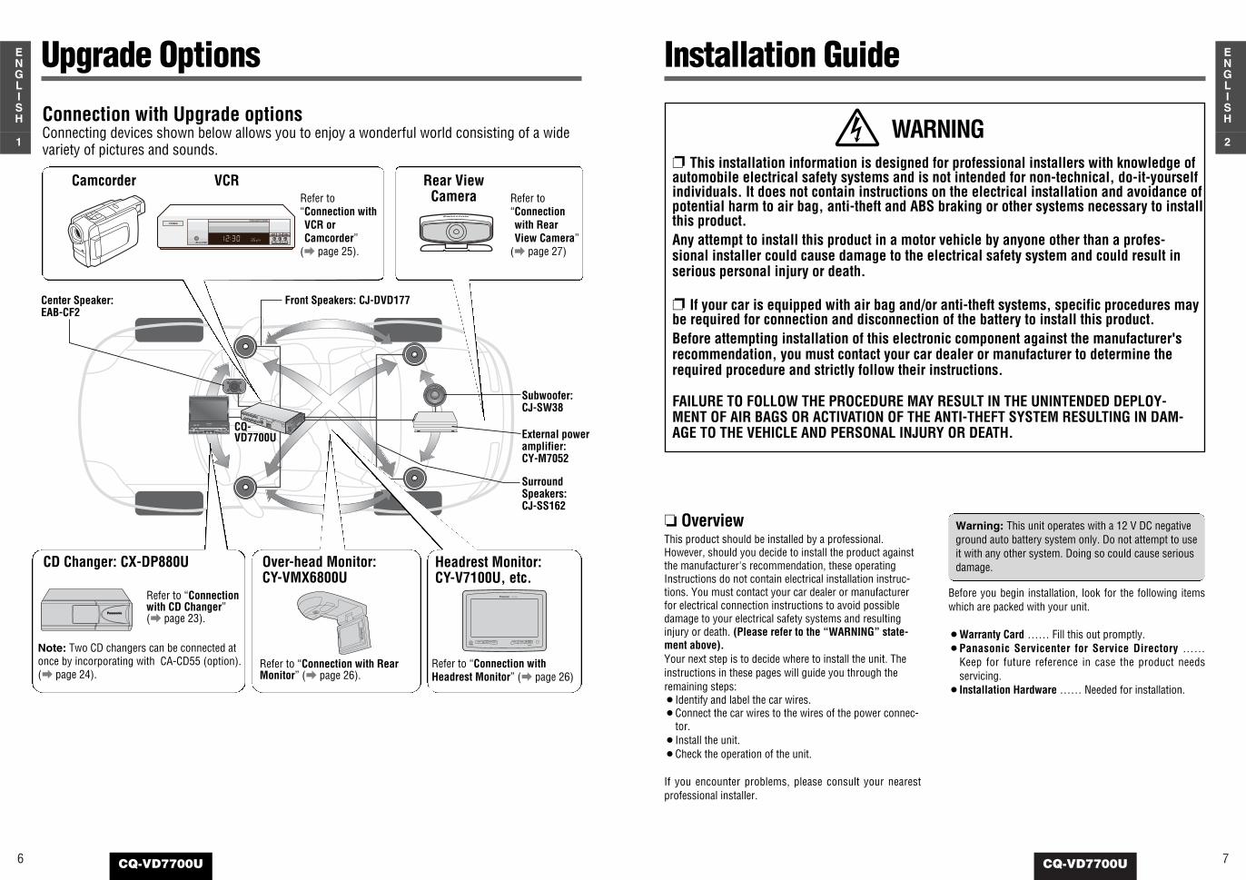
Connection with Upgrade optionsConnecting devices shown below allows you to enjoy a wonderful world consisting of a widevariety of pictures and sounds.
Panasonic
Camcorder Rear ViewCamera
INTELLIGENT SYSTEM
BS G-CODE
POWER
VCRRefer to “Connection withVCR orCamcorder”
(a page 25).
Refer to “Connectionwith RearView Camera”
(a page 27)
Front Speakers: CJ-DVD177
Subwoofer: CJ-SW38
Center Speaker: EAB-CF2
External poweramplifier: CY-M7052
SurroundSpeakers: CJ-SS162
Installation Guide
WARNING This installation information is designed for professional installers with knowledge ofautomobile electrical safety systems and is not intended for non-technical, do-it-yourselfindividuals. It does not contain instructions on the electrical installation and avoidance ofpotential harm to air bag, anti-theft and ABS braking or other systems necessary to installthis product.Any attempt to install this product in a motor vehicle by anyone other than a profes-sional installer could cause damage to the electrical safety system and could result inserious personal injury or death.
If your car is equipped with air bag and/or anti-theft systems, specific procedures maybe required for connection and disconnection of the battery to install this product.Before attempting installation of this electronic component against the manufacturer'srecommendation, you must contact your car dealer or manufacturer to determine therequired procedure and strictly follow their instructions.
FAILURE TO FOLLOW THE PROCEDURE MAY RESULT IN THE UNINTENDED DEPLOY-MENT OF AIR BAGS OR ACTIVATION OF THE ANTI-THEFT SYSTEM RESULTING IN DAM-AGE TO THE VEHICLE AND PERSONAL INJURY OR DEATH.
OverviewThis product should be installed by a professional.However, should you decide to install the product againstthe manufacturer's recommendation, these operatingInstructions do not contain electrical installation instruc-tions. You must contact your car dealer or manufacturerfor electrical connection instructions to avoid possibledamage to your electrical safety systems and resultinginjury or death. (Please refer to the “WARNING” state-ment above).Your next step is to decide where to install the unit. Theinstructions in these pages will guide you through theremaining steps:¡Identify and label the car wires.¡Connect the car wires to the wires of the power connec-
tor.¡Install the unit.¡Check the operation of the unit.
If you encounter problems, please consult your nearestprofessional installer.
Warning: This unit operates with a 12 V DC negativeground auto battery system only. Do not attempt to useit with any other system. Doing so could cause seriousdamage.
Before you begin installation, look for the following itemswhich are packed with your unit.
¡Warranty Card …… Fill this out promptly.¡Panasonic Servicenter for Service Directory ……
Keep for future reference in case the product needsservicing.
¡Installation Hardware …… Needed for installation.
CY-V7100U
PHONES
Headrest Monitor:CY-V7100U, etc.
Refer to “Connection withHeadrest Monitor” (a page 26)
CD Changer: CX-DP880U
Note: Two CD changers can be connected atonce by incorporating with CA-CD55 (option).(a page 24).
Over-head Monitor:CY-VMX6800U
Refer to “Connection with RearMonitor” (a page 26).
Refer to “Connectionwith CD Changer”(a page 23).
9CQ-VD7700U
4
ENGLISH
8 CQ-VD7700U
3
ENGLISH
Installation Guide (continued)
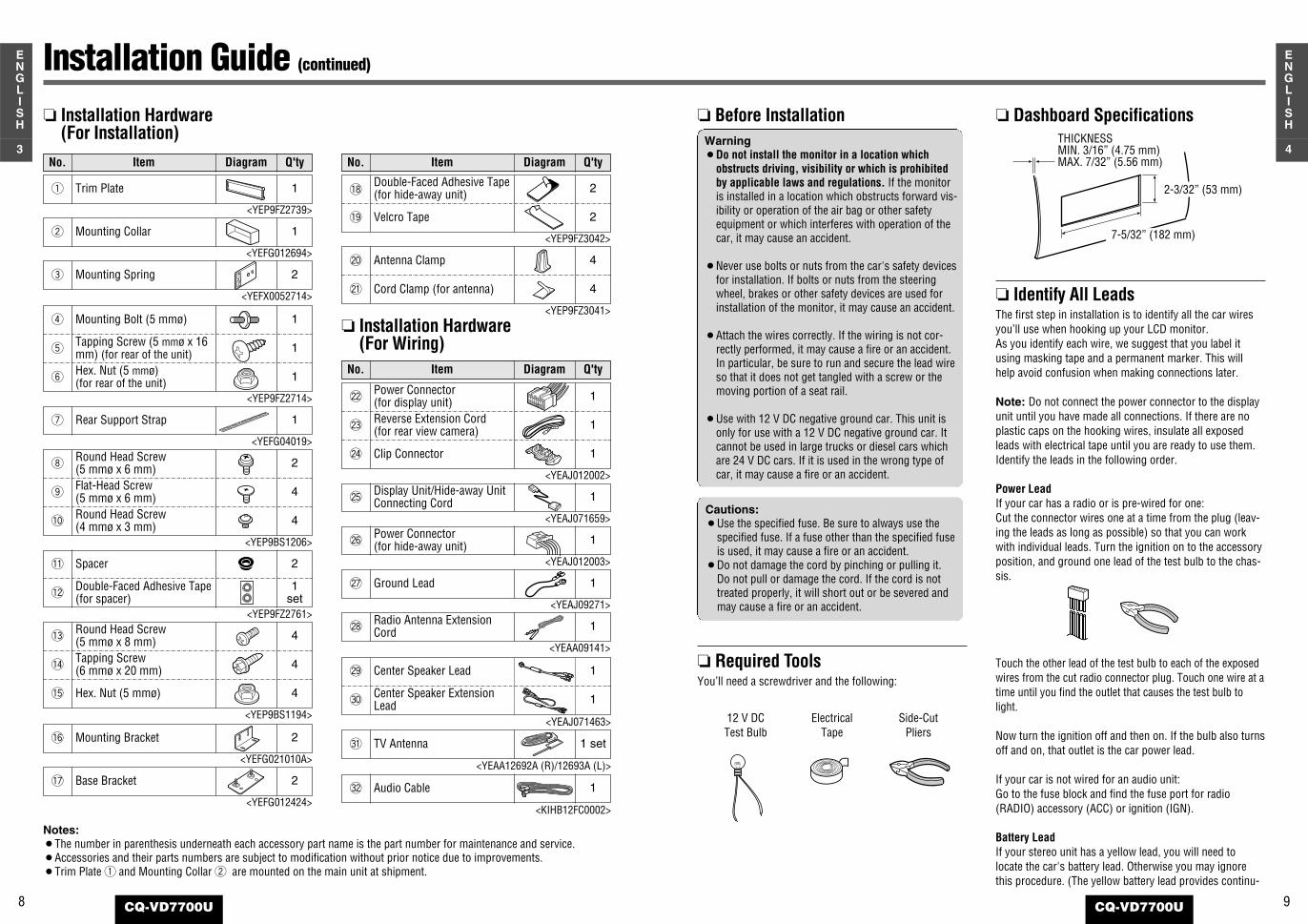
Notes:¡The number in parenthesis underneath each accessory part name is the part number for maintenance and service.¡Accessories and their parts numbers are subject to modification without prior notice due to improvements.¡Trim Plate q and Mounting Collar w are mounted on the main unit at shipment.
TV Antenna#1 1 set
Audio Cable#2 1
Before InstallationWarning¡Do not install the monitor in a location which
obstructs driving, visibility or which is prohibitedby applicable laws and regulations. If the monitoris installed in a location which obstructs forward vis-ibility or operation of the air bag or other safetyequipment or which interferes with operation of thecar, it may cause an accident.
¡Never use bolts or nuts from the car's safety devicesfor installation. If bolts or nuts from the steeringwheel, brakes or other safety devices are used forinstallation of the monitor, it may cause an accident.
¡Attach the wires correctly. If the wiring is not cor-rectly performed, it may cause a fire or an accident.In particular, be sure to run and secure the lead wireso that it does not get tangled with a screw or themoving portion of a seat rail.
¡Use with 12 V DC negative ground car. This unit isonly for use with a 12 V DC negative ground car. Itcannot be used in large trucks or diesel cars whichare 24 V DC cars. If it is used in the wrong type ofcar, it may cause a fire or an accident.
Required ToolsYou’ll need a screwdriver and the following:
12 V DCTest Bulb
ElectricalTape
Side-CutPliers
Cautions:¡Use the specified fuse. Be sure to always use the
specified fuse. If a fuse other than the specified fuseis used, it may cause a fire or an accident.
¡Do not damage the cord by pinching or pulling it.Do not pull or damage the cord. If the cord is nottreated properly, it will short out or be severed andmay cause a fire or an accident.
Dashboard Specifications
Identify All LeadsThe first step in installation is to identify all the car wiresyou’ll use when hooking up your LCD monitor.As you identify each wire, we suggest that you label itusing masking tape and a permanent marker. This willhelp avoid confusion when making connections later.
Note: Do not connect the power connector to the displayunit until you have made all connections. If there are noplastic caps on the hooking wires, insulate all exposedleads with electrical tape until you are ready to use them.Identify the leads in the following order.
Power LeadIf your car has a radio or is pre-wired for one:Cut the connector wires one at a time from the plug (leav-ing the leads as long as possible) so that you can workwith individual leads. Turn the ignition on to the accessoryposition, and ground one lead of the test bulb to the chas-sis.
Touch the other lead of the test bulb to each of the exposedwires from the cut radio connector plug. Touch one wire at atime until you find the outlet that causes the test bulb tolight.
Now turn the ignition off and then on. If the bulb also turnsoff and on, that outlet is the car power lead.
If your car is not wired for an audio unit: Go to the fuse block and find the fuse port for radio(RADIO) accessory (ACC) or ignition (IGN).
Battery LeadIf your stereo unit has a yellow lead, you will need tolocate the car's battery lead. Otherwise you may ignorethis procedure. (The yellow battery lead provides continu-
THICKNESSMIN. 3/16” (4.75 mm)MAX. 7/32” (5.56 mm)
2-3/32” (53 mm)
7-5/32” (182 mm)
@9 Center Speaker Lead 1
#0Center Speaker ExtensionLead 1
Installation Hardware (For Installation)
Installation Hardware (For Wiring)
Q'tyDiagramItemNo. Q'tyDiagramItemNo.
Trim Plate
<YEP9FZ2739>
q 1
Mounting Bracket
<YEFG021010A>
!6 2
Base Bracket
<YEFG012424>
!7 2
Mounting Collar
<YEFG012694>
w 1
Mounting Spring
<YEFX0052714>
e 2
Rear Support Strap
<YEFG04019>
<YEP9BS1206>
u 1
Display Unit/Hide-away UnitConnecting Cord
<YEAJ071659>
@5 1
Power Connector(for hide-away unit)
<YEAJ012003>
@6 1
Ground Lead
<YEAJ09271>
@7 1
Radio Antenna ExtensionCord
<YEAA09141>
@8 1
Round Head Screw(5 mmø x 6 mm)i 2
Flat-Head Screw(5 mmø x 6 mm)o 4
Round Head Screw(4 mmø x 3 mm)!0 4
<YEAJ012002>
Power Connector (for display unit)@2 1
Reverse Extension Cord(for rear view camera)@3 1
Clip Connector@4 1
<YEP9BS1194>
Round Head Screw (5 mmø x 8 mm)!3 4
Tapping Screw (6 mmø x 20 mm)!4 4
Hex. Nut (5 mmø)!5 4
Q'tyDiagramItemNo.
<YEP9FZ2714>
Mounting Bolt (5 mmø)r 1
Tapping Screw (5 mmø x 16mm) (for rear of the unit)t 1
Hex. Nut (5 mmø)(for rear of the unit)y 1
<YEP9FZ2761>
Spacer!1 2
Double-Faced Adhesive Tape(for spacer)!2
1 set
<YEP9FZ3042>
Double-Faced Adhesive Tape(for hide-away unit)!8 2
Velcro Tape!9 2
<YEP9FZ3041>
Antenna Clamp@0 4
Cord Clamp (for antenna)@1 4
<YEAJ071463>
<YEAA12692A (R)/12693A (L)>
<KIHB12FC0002>

11CQ-VD7700U
6
ENGLISH
10 CQ-VD7700U
5
ENGLISH
ous power to maintain a clock or other functions.)
If your car has a radio or is pre-wired for one:With the ignition and headlights off, identify the car batterylead by grounding one lead of the test bulb to the chassisand checking the remaining exposed wires from the cutradio connector plug.
If your car is not wired for an audio unit: Go to the fuse block and find the fuse port for the battery,usually marked BAT.
Speakers (not supplied)Identify the car speaker leads. There are two leads for eachspeaker, usually color coded.A handy way to identify the speaker leads and the speakerthey are connected with is to test the leads using a 1.5 VAA battery as follows.Hold one lead against one pole of the battery and strokethe other lead across the other pole. You will hear a scrap-ing sound in a speaker if you are holding a speaker lead.If not, keep testing different lead combinations until youhave located all the speaker leads. When you label them,include the speaker location for each.
Connect All LeadsNow that you have identified all the wires in the car, you'reready to begin connecting them to the LCD monitor wires.Electrical Connections (a page 18-27) shows the properconnections and color coding of the leads.We strongly recommend that you test the unit before mak-ing a final installation.You can set the unit on the floor and make temporary con-nections to test the unit. Use electrical tape to cover allexposed wires.
Important: Connect the red power lead last, after youhave made and insulated all other connections.
GroundConnect the black ground lead of the power connector tothe metal car chassis.
SpeakersConnect the speaker wires. See the wiring diagram for theproper hookups. Follow the diagram carefully to avoiddamaging the speakers and the stereo unit.The speakers used must be able to handle more than 70 W(Center Speaker: 35W) of audio power. If using an optionalaudio power, the speakers should be able to handle themaximum amplifier output power. Speakers with low inputratings can be damaged.
Speaker impedance should measure 4–8 Ω, which is typi-cally marked on most speakers. Lower or higher imped-ance speakers will affect output and can cause both speak-er and stereo unit damage.
BatteryConnect the yellow battery lead to the correct radio wire orto the battery fuse port on the fuse block.
EquipmentConnect any optional equipment according to the instruc-tions furnished with the equipment. Read the operatingand installation instructions of any equipment you willconnect to this unit.
PowerConnect the red power lead to the correct car radio wire orto the appropriate fuse port on the fuse block.If the LCD monitor functions properly with all these con-nections made, disconnect the wires and proceed to thefinal installation.
Final Installation Lead ConnectionsConnect all wires, making sure that each connection isinsulated and secure. Bundle all loose wires and fastenthem with tape so they will not fall down later. Now insertthe LCD monitor into the mounting collar.
Congratulations! After making a few final checks, you’reready to enjoy your new LCD monitor.
Final Checks1. Make sure that all wires are properly connected and
insulated.2. Make sure that the LCD monitor is securely held in
the mounting collar. 3. Turn on the ignition to check the unit for proper
operation.
If you have difficulties, consult your nearest authorizedprofessional installer for assistance.
Caution: Never ground the speaker cords. For exam-ple, do not use a chassis ground system or a three-wire speaker common system. Each speaker must beconnected separately using parallel insulated wires. Ifin doubt about how your car’s speakers are wired,please consult with your nearest professional installer.
Precautions
¡Disconnect the cable from the negative (–) battery ter-minal (see caution at right).
¡Unit should be installed in a horizontal position with thefront end up at a convenient angle, but less than 30°.
Warning: If your car is equipped with air bagand/or anti-theft systems, specific proceduresmay be required for connection and disconnec-tion of the battery to install this product.Before attempting installation of this electroniccomponent against the manufacturer's recom-mendation, you must contact your car dealer ormanufacturer to determine the required proce-dure and strictly follow their instructions.FAILURE TO FOLLOW THE PROCEDURE MAYRESULT IN THE UNINTENDED DEPLOYMENT OFAIR BAGS OR ACTIVATION OF THE ANTI-THEFTSYSTEM RESULTING IN DAMAGE TO THE VEHI-CLE AND PERSONAL INJURY OR DEATH.
Cautions:¡We strongly recommend that you wear gloves for
installation work to protect yourself from injuries.¡When bending the mounting tab of the mounting
collar with a screwdriver, be careful not to injureyour hands and fingers.
This unit should be professionally installed. In case of dif-ficulty, please consult with your nearest professionalinstaller.1. This unit only operates in a 12 V DC negative ground
system.2. Follow the Electrical Connections carefully (a page 18-
27). Failure to do so may result in damage to the unit.3. Connect the power lead after all other connections are
made.4. Be sure to connect the battery lead (yellow) to the posi-
tive terminal (+) of the battery or fuse block (BAT) ter-minal.
5. Insulate all exposed wires to prevent short circuiting.6. Secure all loose wires after installing the unit.7. Please carefully read the operating and installation
instructions of the respective equipment before con-necting it to this unit.
Caution: Please follow the laws and regulations ofyour state, province or country for installation of theunit.
Caution: Various settings that have been stored in thememory in other on-board equipment (car navigationetc.) may be lost if the battery terminals are discon-nected.Therefore, Therefore, we recommend you to make arecord of or to back up the settings before disconnect-ing the terminals. After completing installation of the main unit, set up theequipment again according to the settings.
less than 30°
Display Unit
Round Head Screw(5 mmø x 6 mm)
Round Head Screw(5 mmø x 6 mm)
TransportationBracket
TransportationBracket
Transportation Bracket RemovalBe sure to remove the transportation brackets before use (installation).Use Round Head Screws (5 mmø x 6 mm) for installation. (a page 14)Be careful not to lose these Round Head Screws.
Installation Guide (continued)
13CQ-VD7700U
8
ENGLISH
12 CQ-VD7700U
7
ENGLISH
Installation Guide (continued)
1
3
56
2
4
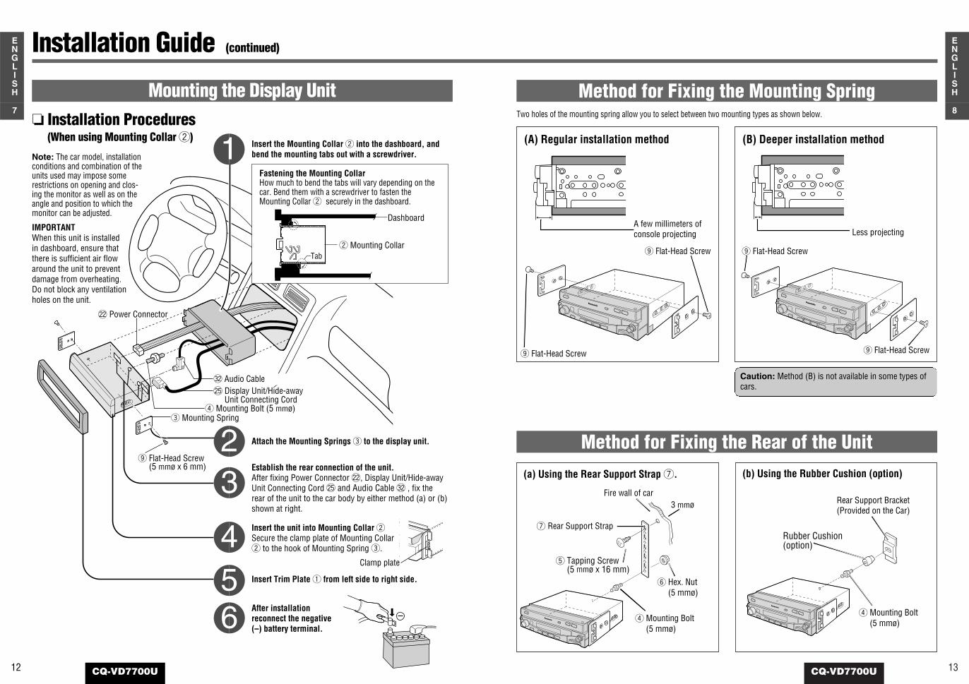
Installation Procedures(When using Mounting Collar w)
Mounting the Display Unit
Insert the Mounting Collar w into the dashboard, andbend the mounting tabs out with a screwdriver.
Establish the rear connection of the unit.After fixing Power Connector @2, Display Unit/Hide-awayUnit Connecting Cord @5 and Audio Cable #2 , fix therear of the unit to the car body by either method (a) or (b)shown at right.
Insert Trim Plate q from left side to right side.
After installationreconnect the negative(–) battery terminal.
Attach the Mounting Springs e to the display unit.
@2 Power Connector
@5 Display Unit/Hide-awayUnit Connecting Cord
#2 Audio Cable
r Mounting Bolt (5 mmø)e Mounting Spring
o Flat-Head Screw (5 mmø x 6 mm)
Fastening the Mounting CollarHow much to bend the tabs will vary depending on thecar. Bend them with a screwdriver to fasten theMounting Collar w securely in the dashboard.
w Mounting Collar
Dashboard
Tab
Insert the unit into Mounting Collar wSecure the clamp plate of Mounting Collarw to the hook of Mounting Spring e.
Clamp plate
Two holes of the mounting spring allow you to select between two mounting types as shown below.
A few millimeters of console projecting Less projecting
Method for Fixing the Rear of the Unit
Method for Fixing the Mounting Spring
(A) Regular installation method (B) Deeper installation method
o Flat-Head Screw
o Flat-Head Screw
o Flat-Head Screw
o Flat-Head Screw
(a) Using the Rear Support Strap u. (b) Using the Rubber Cushion (option)
Fire wall of car3 mmø
t Tapping Screw (5 mmø x 16 mm)
u Rear Support Strap
r Mounting Bolt(5 mmø)
r Mounting Bolt(5 mmø)
Rear Support Bracket(Provided on the Car)
Rubber Cushion(option)
y Hex. Nut(5 mmø)
Caution: Method (B) is not available in some types ofcars.
Note: The car model, installationconditions and combination of theunits used may impose somerestrictions on opening and clos-ing the monitor as well as on theangle and position to which themonitor can be adjusted.
IMPORTANTWhen this unit is installedin dashboard, ensure thatthere is sufficient air flowaround the unit to preventdamage from overheating.Do not block any ventilationholes on the unit.
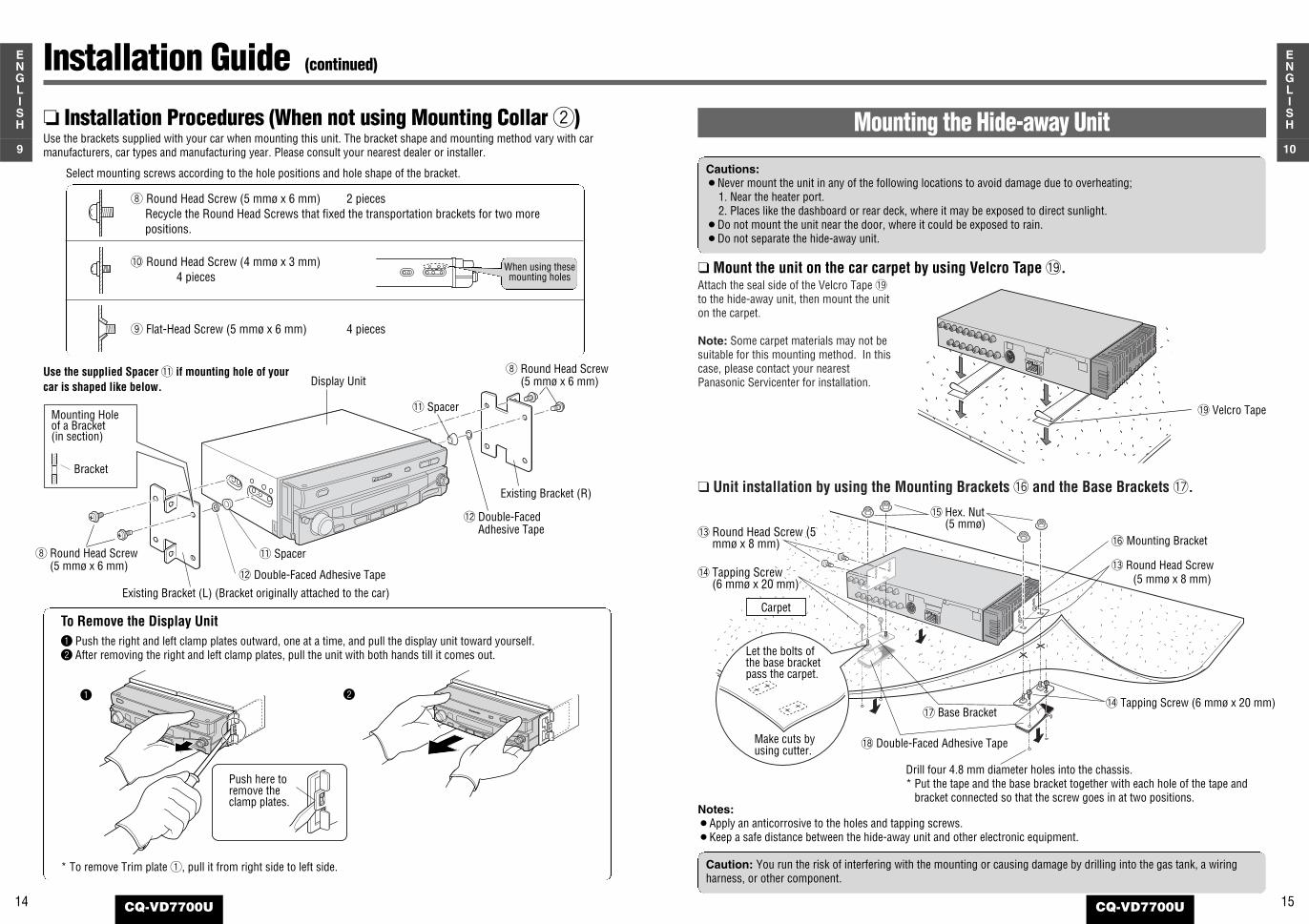
Attach the seal side of the Velcro Tape !9to the hide-away unit, then mount the uniton the carpet.
Note: Some carpet materials may not besuitable for this mounting method. In thiscase, please contact your nearestPanasonic Servicenter for installation.
Unit installation by using the Mounting Brackets !6 and the Base Brackets !7.
!9 Velcro Tape
!5 Hex. Nut(5 mmø)
!3 Round Head Screw (5mmø x 8 mm)
!4 Tapping Screw(6 mmø x 20 mm)
Carpet
!6 Mounting Bracket
!3 Round Head Screw(5 mmø x 8 mm)
!4 Tapping Screw (6 mmø x 20 mm)
!8 Double-Faced Adhesive Tape
Drill four 4.8 mm diameter holes into the chassis.* Put the tape and the base bracket together with each hole of the tape and
bracket connected so that the screw goes in at two positions.
!7 Base Bracket
Let the bolts ofthe base bracketpass the carpet.
Make cuts byusing cutter.
Notes:¡Apply an anticorrosive to the holes and tapping screws.¡Keep a safe distance between the hide-away unit and other electronic equipment.
Mount the unit on the car carpet by using Velcro Tape !9.
Mounting the Hide-away Unit
Cautions:¡Never mount the unit in any of the following locations to avoid damage due to overheating;
1. Near the heater port.2. Places like the dashboard or rear deck, where it may be exposed to direct sunlight.
¡Do not mount the unit near the door, where it could be exposed to rain.¡Do not separate the hide-away unit.
Caution: You run the risk of interfering with the mounting or causing damage by drilling into the gas tank, a wiringharness, or other component.
Installation Guide (continued)
Display Unit
!1 Spacer
!2 Double-Faced Adhesive Tape
i Round Head Screw (5 mmø x 6 mm)
Bracket
Mounting Holeof a Bracket(in section)
Existing Bracket (L) (Bracket originally attached to the car)
!2 Double-Faced Adhesive Tape
Existing Bracket (R)
i Round Head Screw(5 mmø x 6 mm)
!1 Spacer
Installation Procedures (When not using Mounting Collar w)Use the brackets supplied with your car when mounting this unit. The bracket shape and mounting method vary with carmanufacturers, car types and manufacturing year. Please consult your nearest dealer or installer.
Select mounting screws according to the hole positions and hole shape of the bracket.
o Flat-Head Screw (5 mmø x 6 mm) 4 pieces
!0 Round Head Screw (4 mmø x 3 mm)4 pieces
i Round Head Screw (5 mmø x 6 mm) 2 piecesRecycle the Round Head Screws that fixed the transportation brackets for two more positions.
When using thesemounting holes
q Push the right and left clamp plates outward, one at a time, and pull the display unit toward yourself.w After removing the right and left clamp plates, pull the unit with both hands till it comes out.
* To remove Trim plate q, pull it from right side to left side.
Push here toremove theclamp plates.
q w
To Remove the Display Unit
Use the supplied Spacer !1 if mounting hole of yourcar is shaped like below.
15CQ-VD7700U
10
ENGLISH
14 CQ-VD7700U
9
ENGLISH
17CQ-VD7700U
12
ENGLISH
16 CQ-VD7700U
11
ENGLISH
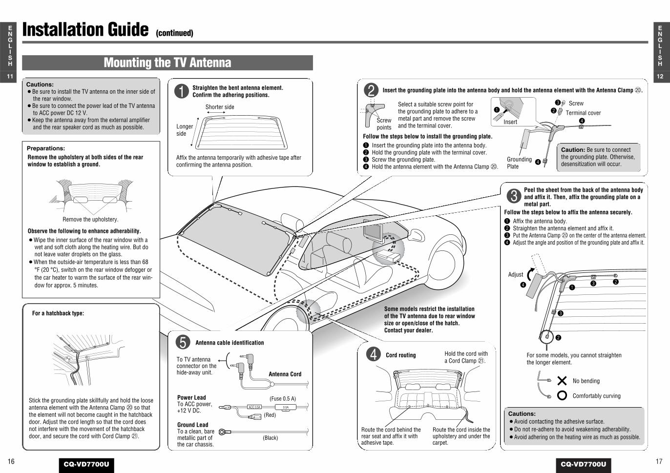
Peel the sheet from the back of the antenna bodyand affix it. Then, affix the grounding plate on ametal part.
Insert the grounding plate into the antenna body and hold the antenna element with the Antenna Clamp @0.
Follow the steps below to affix the antenna securely.q Affix the antenna body.w Straighten the antenna element and affix it.e Put the Antenna Clamp @0 on the center of the antenna element.r Adjust the angle and position of the grounding plate and affix it.
Follow the steps below to install the grounding plate.q Insert the grounding plate into the antenna body.w Hold the grounding plate with the terminal cover.e Screw the grounding plate.r Hold the antenna element with the Antenna Clamp @0.
Select a suitable screw point forthe grounding plate to adhere to ametal part and remove the screwand the terminal cover.
For some models, you cannot straightenthe longer element.
No bending
Comfortably curving
2
3
Caution: Be sure to connectthe grounding plate. Otherwise,desensitization will occur.r
r
q w
e Screw
Terminal coverInsert
GroundingPlate
Screwpoints
Cautions:¡Avoid contacting the adhesive surface.¡Do not re-adhere to avoid weakening adherability.¡Avoid adhering on the heating wire as much as possible.
r qw
e
w
e
Adjust
Cord routing
Route the cord behind therear seat and affix it withadhesive tape.
Hold the cord witha Cord Clamp @1.
Route the cord inside theupholstery and under thecarpet.
Some models restrict the installationof the TV antenna due to rear windowsize or open/close of the hatch.Contact your dealer.
4
For a hatchback type:
Stick the grounding plate skillfully and hold the looseantenna element with the Antenna Clamp @0 so thatthe element will not become caught in the hatchbackdoor. Adjust the cord length so that the cord doesnot interfere with the movement of the hatchbackdoor, and secure the cord with Cord Clamp @1.
Installation Guide (continued)
Mounting the TV Antenna
Antenna cable identification
0.5AACC 0.5A
Cautions:¡Be sure to install the TV antenna on the inner side of
the rear window.¡Be sure to connect the power lead of the TV antenna
to ACC power DC 12 V.¡Keep the antenna away from the external amplifier
and the rear speaker cord as much as possible.
5
Preparations:
Remove the upholstery.
Remove the upholstery at both sides of the rearwindow to establish a ground.
Observe the following to enhance adherability.¡Wipe the inner surface of the rear window with a
wet and soft cloth along the heating wire. But donot leave water droplets on the glass.
¡When the outside-air temperature is less than 68°F (20 °C), switch on the rear window defogger orthe car heater to warm the surface of the rear win-dow for approx. 5 minutes.
Power LeadTo ACC power,+12 V DC.
Ground LeadTo a clean, baremetallic part ofthe car chassis.
(Red)
(Black)
(Fuse 0.5 A)
Antenna Cord
To TV antennaconnector on thehide-away unit.
Straighten the bent antenna element.Confirm the adhering positions.
Affix the antenna temporarily with adhesive tape afterconfirming the antenna position.
1Shorter side
Longerside

19CQ-VD7700U
14
ENGLISH
18 CQ-VD7700U
13
ENGLISH
BATTERY 5A
VIDEO-CONT
SIDE BRAKE
REVERSE
CAMERA-IN
Hide-away Unit
(Front)
(Rear)
Note: See next page for hide-away unitelectrical connection.
Wiring Diagram
Electrical Connections
Accessory used for wiring
RGB Input CordTo the RGB Connector of the Panasoniccar navigation system (available in future).
(Green/yellow stripe)
@5 Display Unit/Hide-away Unit Connecting Cord
(Blue/yellow stripe)
(Violet/white stripe)
(Black)(Noise Filter)
(Yellow)
(Black)
Video Control LeadTo the Video Control Lead of thePanasonic car navigation system(available in future).
Side Brake (Parking Brake) ConnectionLeadBe sure to wire the side brake (parkingbrake) for safety and preventing accidents.(a page 22)
Reverse LeadWhen connecting the rear view camera,use the reverse lead. (a page 27)
Battery LeadTo the car battery, continuous +12 V DC.
Ground LeadTo a clean, bare metallic part of the carchassis.
Note: Use a Reverse Extension Cord @3 ifneeded.
(Fuse 5 A)
Camera InputTo the rear view camera
※ Remove the vinyl capwhen connecting.
Display Unit (Rear)
@2 Power ConnectorAudio OutputConnector
Notes: ¡To prevent damage to the unit, be sure to follow the connection diagram below.¡Be sure to fully plug in the connectors. Secure them with clamps and tape.¡When game machines are connected, the picture may be unstable.¡When removing the Power Connector @2 and Display Unit/Hide-away Unit Connecting Cord @5, be sure to press the clip.¡All other installation methods require the use of dedicated metal fittings. Consult with a qualified servicing engineer or your
dealer if other methods are required.
Cautions: ¡This unit is designed for use in a car having a 12 V negative ground battery system.¡Be sure to insulate any exposed wires from a possible short-circuit from the car chassis. Bundle all cables and keep
cable terminals free from touching any metal parts.¡Note that if your car has a driving computer or a navigation computer, disconnecting the cable from the battery may
clear the memory.¡Install the cords avoiding the spots where the temperature can be extremely high.
Caution: Do notinsert the powerconnector into theunit until the wiringis completed.
※
@7 Ground LeadTo a clean, bare metallic part of thecar chassis
#2 Audio Cable
No. Item Q'ty
Power Connector (for display unit) 1@2
Reverse Extension Cord (for rear viewcamera) 1@3
Clip Connector 1@4
Display Unit/Hide-away UnitConnecting Cord 1@5
Power Connector (for hide-away unit) 1@6
No. Item Q'ty
Ground Lead 1@7
Radio Antenna Extension Cord 1@8
Center Speaker Lead 1@9
Center Speaker Extension Lead 1#0
TV Antenna 1 set#1
Audio Cable 1#2
Note: Ground Lead @7 shouldbe grounded to the point thatis also used as the groundingpoint for the display unit if youcan.
21CQ-VD7700U
16
ENGLISH
20 CQ-VD7700U
15
ENGLISH
BATTERY 15A
ACC
TWIN CD C-CONT
AMP-CONT MAX 0.1A
ANT-CONT MAX 0.1A
!
@
!
@
!
@
!
@REAR R
FRONT L
FRONT R
REAR L
CENTER
!
@CENTER
NAVI MUTE (Front)
(Rear)
(White/black stripe)
(Gray/black stripe)
(Green/black stripe)
(Violet/black stripe)
(White)
(Black/green stripe)
(Black)
(Gray)
(Green)
(Violet)
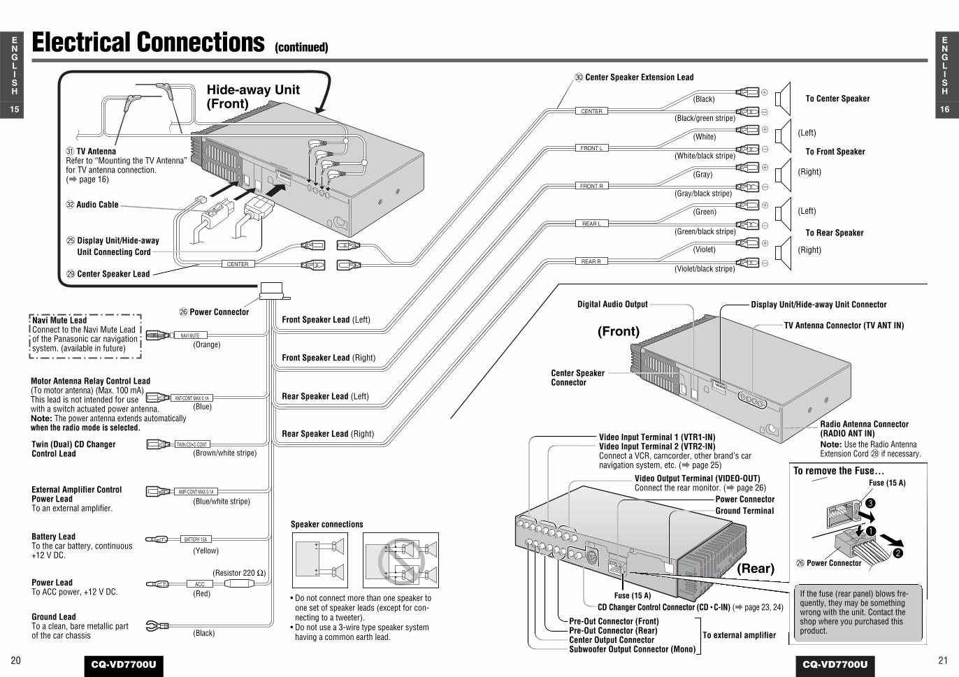
(Left)
(Right)
(Left)
(Right)
To Front Speaker
To Center Speaker
To Rear Speaker
Pre-Out Connector (Front)Pre-Out Connector (Rear)Center Output ConnectorSubwoofer Output Connector (Mono)
Video Input Terminal 1 (VTR1-IN)Video Input Terminal 2 (VTR2-IN)Connect a VCR, camcorder, other brand’s carnavigation system, etc. (a page 25)
Video Output Terminal (VIDEO-OUT)Connect the rear monitor. (a page 26)
Center SpeakerConnector
Radio Antenna Connector (RADIO ANT IN)Note: Use the Radio AntennaExtension Cord @8 if necessary.
To external amplifier
Display Unit/Hide-away Unit Connector
TV Antenna Connector (TV ANT IN)
Electrical Connections (continued)
Motor Antenna Relay Control Lead(To motor antenna) (Max. 100 mA)This lead is not intended for use with a switch actuated power antenna.
Twin (Dual) CD ChangerControl Lead
External Amplifier ControlPower LeadTo an external amplifier.
Battery LeadTo the car battery, continuous+12 V DC.
Power LeadTo ACC power, +12 V DC.
Ground LeadTo a clean, bare metallic partof the car chassis
(Orange)
(Blue)
(Brown/white stripe)
(Blue/white stripe)
(Yellow)
(Red)
(Black)
Note: The power antenna extends automaticallywhen the radio mode is selected.
(Resistor 220 Ω)
@6 Power Connector
Rear Speaker Lead (Right)
Front Speaker Lead (Left)
Front Speaker Lead (Right)
Rear Speaker Lead (Left)
Hide-away Unit(Front)
@5 Display Unit/Hide-awayUnit Connecting Cord
@9 Center Speaker Lead
#1 TV Antenna Refer to “Mounting the TV Antenna”for TV antenna connection. (a page 16)
#2 Audio Cable
CD Changer Control Connector (CD • C-IN) (a page 23, 24)
Digital Audio Output
Power Connector Ground Terminal
Speaker connections
• Do not connect more than one speaker toone set of speaker leads (except for con-necting to a tweeter).
• Do not use a 3-wire type speaker systemhaving a common earth lead.
#0 Center Speaker Extension Lead
To remove the Fuse...
3
1
2
If the fuse (rear panel) blows fre-quently, they may be somethingwrong with the unit. Contact theshop where you purchased thisproduct.
@6 Power Connector
Fuse (15 A)
Fuse (15 A)
Navi Mute Lead Connect to the Navi Mute Leadof the Panasonic car navigationsystem. (available in future)
23CQ-VD7700U
18
ENGLISH
22 CQ-VD7700U
17
ENGLISH
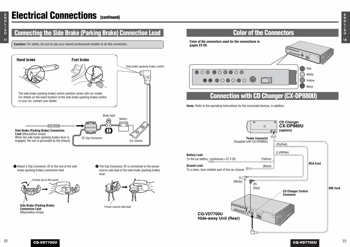
Connection with CD Changer (CX-DP880U) Note: Refer to the operating instructions for the connected devices, in addition.
CQ-VD7700UHide-away Unit (Rear)
DIN CordCD Changer ControlConnector
Electrical Connections (continued)
—+SIDE BRAKE
Caution: For safety, be sure to ask your nearest professional installer to do this connection.
The side brake (parking brake) switch position varies with car model.For details on the exact location of the side brake (parking brake) switchin your car, contact your dealer.
q Attach a Clip Connector @4 to the end of the sidebrake (parking brake) connection lead.
w The Clip Connector @4 is connected to the powersource side lead of the side brake (parking brake)lever.
Connecting the Side Brake (Parking Brake) Connection Lead
Hand brake Foot brake
Side Brake (Parking Brake) ConnectionLead (Blue/yellow stripe)When the side brake (parking brake) lever isengaged, the unit is grounded by the chassis.
Side brake (parking brake) switch
Car chassis
BatteryBrake light
@4 Clip Connector
Side Brake (Parking Brake)Connection Lead(Blue/yellow stripe)
Comes up to this point.
Power source side lead
Color of the ConnectorsColor of the connectors used for the connections inpages 23-26.
White
Red
Yellow
Black
CD ChangerCX-DP880U(option)
Power Connector(Supplied with CX-DP880U)
RCA Cord
(R)(Red)
(L)(White)
(R)(Red)
Battery Lead To the car battery, continuous +12 V DC
Ground Lead To a clean, bare metallic part of the car chassis
(L)(White)
(Yellow)
(Black)
25CQ-VD7700U
20
ENGLISH
24 CQ-VD7700U
19
ENGLISH
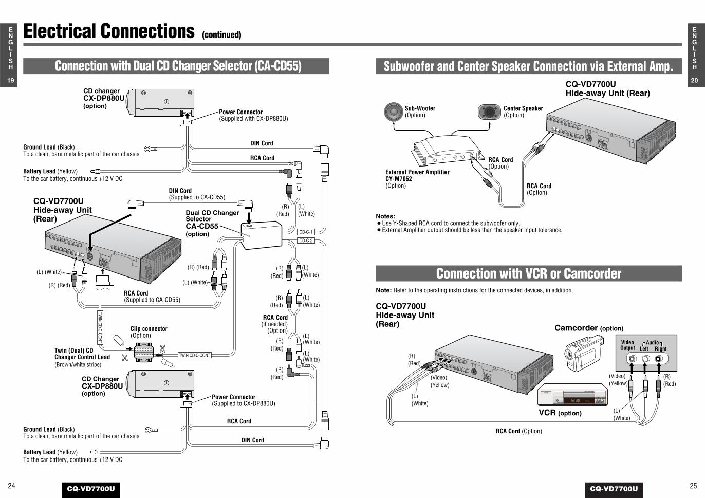
Electrical Connections (continued)
Connection with Dual CD Changer Selector (CA-CD55)
INTELLIGENT SYSTEM
BS G-CODE
POWER
Connection with VCR or CamcorderNote: Refer to the operating instructions for the connected devices, in addition.
Subwoofer and Center Speaker Connection via External Amp.
Notes:¡Use Y-Shaped RCA cord to connect the subwoofer only.¡External Amplifier output should be less than the speaker input tolerance.
CQ-VD7700UHide-away Unit(Rear)
(R)(Red)
(L)(White)
(Video)(Yellow)
VCR (option)
Camcorder (option)
(R)(Red)
(L)(White)
(Video)(Yellow)
RCA Cord (Option)
RCA Cord(Option)
RCA Cord(Option)
Sub-Woofer(Option)
Center Speaker(Option)
External Power AmplifierCY-M7052(Option)
CQ-VD7700UHide-away Unit (Rear)
CD·C-1
CD·C-2
TWIN CD·C-CO
NT
TWIN CD·C-CONT
CD changerCX-DP880U(option)
DIN Cord(Supplied to CA-CD55)
RCA Cord(Supplied to CA-CD55)
Clip connector(Option)
(L)(White)
(L)(White)
(L)(White)
(L)(White)
(L)(White)
(L) (White)
(R) (Red)
(R)(Red)
(R)(Red)
(R)(Red)
(R)(Red)
(R)(Red)
DIN Cord
Battery Lead (Yellow)To the car battery, continuous +12 V DC
Ground Lead (Black)To a clean, bare metallic part of the car chassis
RCA Cord
Power Connector(Supplied with CX-DP880U)
Dual CD ChangerSelectorCA-CD55(option)
Battery Lead (Yellow)To the car battery, continuous +12 V DC
Ground Lead (Black)To a clean, bare metallic part of the car chassis
CD ChangerCX-DP880U(option)
DIN Cord
RCA Cord
Power Connector(Supplied to CX-DP880U)
Twin (Dual) CDChanger Control Lead(Brown/white stripe)
CQ-VD7700UHide-away Unit (Rear)
(R) (Red)
RCA Cord(if needed)
(Option)
(L) (White)
VideoOutput Left Right
Audio

27CQ-VD7700U
22
ENGLISH
26 CQ-VD7700U
21
ENGLISH
Electrical Connections (continued)
VTR1-IN
Connection with Rear MonitorNote: Refer to the operating instructions for the connected devices, in addition.
(R)(Red)
(L)(White)
(L) (White)
(R)(Red)
CQ-VD7700UHide-away Unit
(Rear)
Over-head MonitorCY-VMX6800U(option)
RCA Cord (Option)
(Video)(Yellow)
(Video)(Yellow)
Connection with Headrest MonitorNote: Refer to the operating instructions for the connecteddevices, in addition.
Caution: For people sitting in the front seats, pleaseenjoy only audio during driving.
CY-V7100U
ACC 3 A
PHONES
Ground Lead (Black)
ACC Power Lead (Red)
(Rear)(Front)
DIN Connector
Junction Cable(Supplied with CY-V7100U)
VTR 1
VTR 2
(R)(Red)
(L) (White)
(Video)(Yellow)
CY-V7100UDisplay Unit
CY-V7100UHide-away Unit
CQ-VD7700UHide-away Unit(Rear)
RCA cord (option)
(R)(Red)
(L) (White)
(Video)(Yellow)
Power Lead(Supplied with CY-V7100U)
P
RND2L
Panasonic
REVERSE
CAMERA-IN
Connecting the Reverse LeadIf using an optional rear view camera, the reverse lead mustbe connected.Connect the reverse lead (violet/white stripe) to the positive (+)lead of the reverse lamp (the lamp with a clear lens that lightswhen the transmission gear is shifted into the reverse position).Notes:¡Connect the reverse lead after cutting the terminal at the end.¡Use a Reverse Extension Cord @3 if needed.
Connection with Rear View CameraNote: Refer to the operating instructions for the connected devices, in addition.
Rear View Camera (option)
(Video)(Yellow)
RCA Cord (Option)
Rear View CameraControl Unit (option)CQ-VD7700U
Display Unit (Rear)
(Video)(Yellow)
@2 Power Connector
Reverse lampClip connector(option) Battery Car chassis
Transmission gear
Cut here.
Reverse Lead (Violet/white stripe)
Camera Input
Camera Input(Black)
※
※ Remove the vinyl cap when connecting.
Check the reverse lamp.
Take it out of the back ofthe tail lamp mount.