cqm1h-pro01-e/cqm1-pro01-e/c200h-pro27-e programming consoles...
TRANSCRIPT
Cat. No. W341-E1-05
OPERATION MANUAL
SYSMAC CS/CJ SeriesCQM1H-PRO01-E/CQM1-PRO01-E/C200H-PRO27-E
Programming Consoles
SYSMAC CS/CJ SeriesCQM1H-PRO01-E/CQM1-PRO01-E/C200H-PRO27-E Programming ConsolesOperation ManualRevised October 2005

iv
Notice:OMRON products are manufactured for use according to proper procedures by a qualified operatorand only for the purposes described in this manual.
The following conventions are used to indicate and classify precautions in this manual. Always heedthe information provided with them. Failure to heed precautions can result in injury to people or dam-age to property.
!DANGER Indicates an imminently hazardous situation which, if not avoided, will result in death orserious injury. Additionally, there may be severe property damage.
!WARNING Indicates a potentially hazardous situation which, if not avoided, could result in death orserious injury. Additionally, there may be severe property damage.
!Caution Indicates a potentially hazardous situation which, if not avoided, may result in minor ormoderate injury, or property damage.
OMRON Product ReferencesAll OMRON products are capitalized in this manual. The word “Unit” is also capitalized when it refers toan OMRON product, regardless of whether or not it appears in the proper name of the product.
The abbreviation “Ch,” which appears in some displays and on some OMRON products, often means“word” and is abbreviated “Wd” in documentation in this sense.
The abbreviation “PLC” means Programmable Controller. “PC” is used, however, in some Program-ming Device displays to mean Programmable Controller.
Visual AidsThe following headings appear in the left column of the manual to help you locate different types ofinformation.
Note Indicates information of particular interest for efficient and convenient opera-tion of the product.
1,2,3... 1. Indicates lists of one sort or another, such as procedures, checklists, etc.
OMRON, 1999All rights reserved. No part of this publication may be reproduced, stored in a retrieval system, or transmitted, in any form, orby any means, mechanical, electronic, photocopying, recording, or otherwise, without the prior written permission ofOMRON.
No patent liability is assumed with respect to the use of the information contained herein. Moreover, because OMRON is con-stantly striving to improve its high-quality products, the information contained in this manual is subject to change withoutnotice. Every precaution has been taken in the preparation of this manual. Nevertheless, OMRON assumes no responsibilityfor errors or omissions. Neither is any liability assumed for damages resulting from the use of the information contained inthis publication.
v
Unit Versions of CS/CJ-series CPU Units
Unit Versions A “unit version” has been introduced to manage CPU Units in the CS/CJSeries according to differences in functionality accompanying Unit upgrades.This applies to the CS1-H, CJ1-H, CJ1M, and CS1D CPU Units.
Notation of Unit Versions on Products
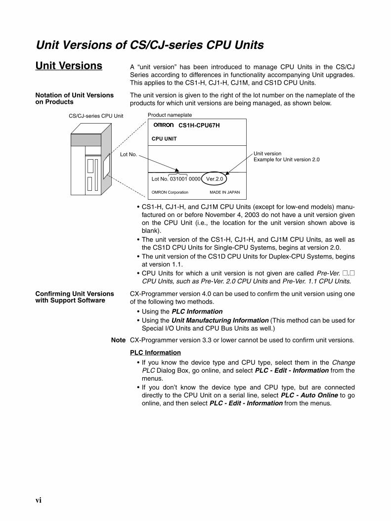
The unit version is given to the right of the lot number on the nameplate of theproducts for which unit versions are being managed, as shown below.
• CS1-H, CJ1-H, and CJ1M CPU Units (except for low-end models) manu-factured on or before November 4, 2003 do not have a unit version givenon the CPU Unit (i.e., the location for the unit version shown above isblank).
• The unit version of the CS1-H, CJ1-H, and CJ1M CPU Units, as well asthe CS1D CPU Units for Single-CPU Systems, begins at version 2.0.
• The unit version of the CS1D CPU Units for Duplex-CPU Systems, beginsat version 1.1.
• CPU Units for which a unit version is not given are called Pre-Ver. @.@CPU Units, such as Pre-Ver. 2.0 CPU Units and Pre-Ver. 1.1 CPU Units.
Confirming Unit Versions with Support Software
CX-Programmer version 4.0 can be used to confirm the unit version using oneof the following two methods.
• Using the PLC Information• Using the Unit Manufacturing Information (This method can be used for
Special I/O Units and CPU Bus Units as well.)
Note CX-Programmer version 3.3 or lower cannot be used to confirm unit versions.
PLC Information
• If you know the device type and CPU type, select them in the ChangePLC Dialog Box, go online, and select PLC - Edit - Information from themenus.
• If you don’t know the device type and CPU type, but are connecteddirectly to the CPU Unit on a serial line, select PLC - Auto Online to goonline, and then select PLC - Edit - Information from the menus.
CS1H-CPU67H
CPU UNIT
Lot No. 031001 0000 Ver.2.0
OMRON Corporation MADE IN JAPAN
CS/CJ-series CPU Unit Product nameplate
Lot No. Unit versionExample for Unit version 2.0
vi
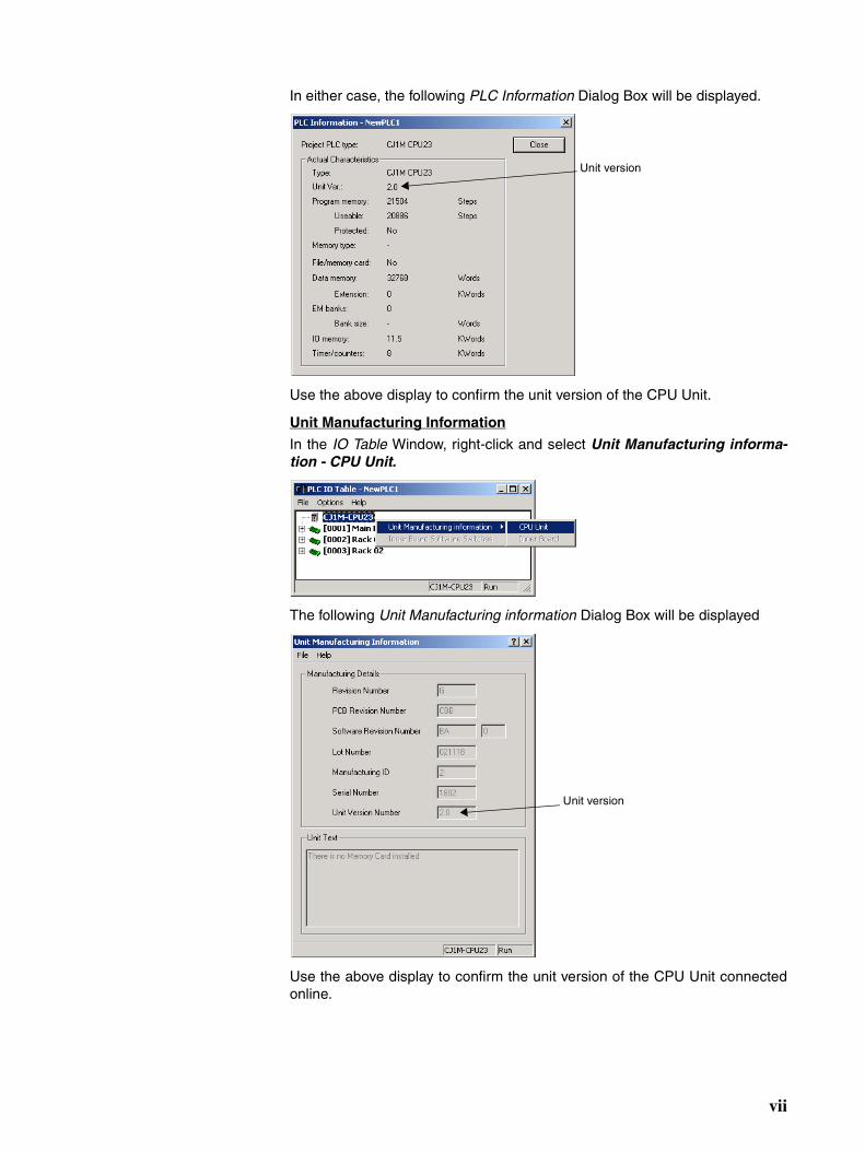
In either case, the following PLC Information Dialog Box will be displayed.
Use the above display to confirm the unit version of the CPU Unit.
Unit Manufacturing Information
In the IO Table Window, right-click and select Unit Manufacturing informa-tion - CPU Unit.
The following Unit Manufacturing information Dialog Box will be displayed
Use the above display to confirm the unit version of the CPU Unit connectedonline.
Unit version
Unit version
vii
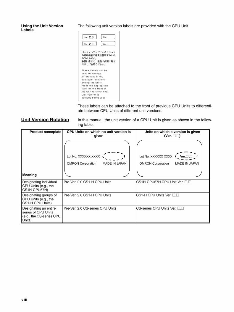
Using the Unit Version Labels
The following unit version labels are provided with the CPU Unit.
These labels can be attached to the front of previous CPU Units to differenti-ate between CPU Units of different unit versions.
Unit Version Notation In this manual, the unit version of a CPU Unit is given as shown in the follow-ing table.
These Labels can beused to managedi f ferences in theavai lab le funct ionsamong the Uni ts .P lace the appropr ia telabel on the f ront o fthe Uni t to show whatUni t vers ion isactua l ly be ing used .
Ver. 2.0
Ver. 2.0
Ver.
Ver.
Product nameplate
Meaning
CPU Units on which no unit version is given
Units on which a version is given (Ver. @.@)
Designating individual CPU Units (e.g., the CS1H-CPU67H)
Pre-Ver. 2.0 CS1-H CPU Units CS1H-CPU67H CPU Unit Ver. @.@
Designating groups of CPU Units (e.g., the CS1-H CPU Units)
Pre-Ver. 2.0 CS1-H CPU Units CS1-H CPU Units Ver. @.@
Designating an entire series of CPU Units (e.g., the CS-series CPU Units)
Pre-Ver. 2.0 CS-series CPU Units CS-series CPU Units Ver. @.@
Lot No. XXXXXX XXXX
OMRON Corporation MADE IN JAPAN
Lot No. XXXXXX XXXX Ver.@@ .@
OMRON Corporation MADE IN JAPAN
viii

Unit Versions and Lot NumbersSeries Model Data of manufacture
Earlier Sept. 2003 Oct. 2003 Nov. 2003 Dec. 2003 Later
CS Series
CS1 CPU Units CS1@-CPU@@No unit version
CS1-V1 CPU Units CS1@-CPU@@-V1
No unit version
CS1-H CPU Units CS1@-CPU@@H
Pre-Ver. 2.0 CPU Units CPU Units Ver. 2.0(Lot No.: 031105 on)
CS1DCPU Units
CPU Units for Duplex-CPU Sys-tem
CS1D-CPU@@H
Pre-Ver. 1.1 CPU Units CPU Units Ver.1.1(Lot No.: 031120 on)
CPU Units for Single-CPU Sys-tem
CS1D-CPU@@S
CPU Units Ver. 2.0(Lot No.: 031215 on)
CJ Series
CJ1 CPU Units CJ1G-CPU@@Pre-Ver. 2.0 CPU Units
CJ1-H CPU Units CJ1@-CPU@@H
Pre-Ver. 2.0 CPU Units CPU Units Ver. 2.0(Lot No.: 031105 on)
CJ1M CPU Units except low-end mod-els
CJ1M-CPU@@
Pre-Ver. 2.0 CPU Units CPU Units Ver. 2.0(Lot No.: 031105 on)
CJ1M CPU Units, low-end models
CJ1M-CPU11/21
Unit Ver. 2.0(Lot No.: 031002 on)
Sup-port Soft-ware
CX-Programmer [email protected] Ver.3.3 Ver.4.0
ix
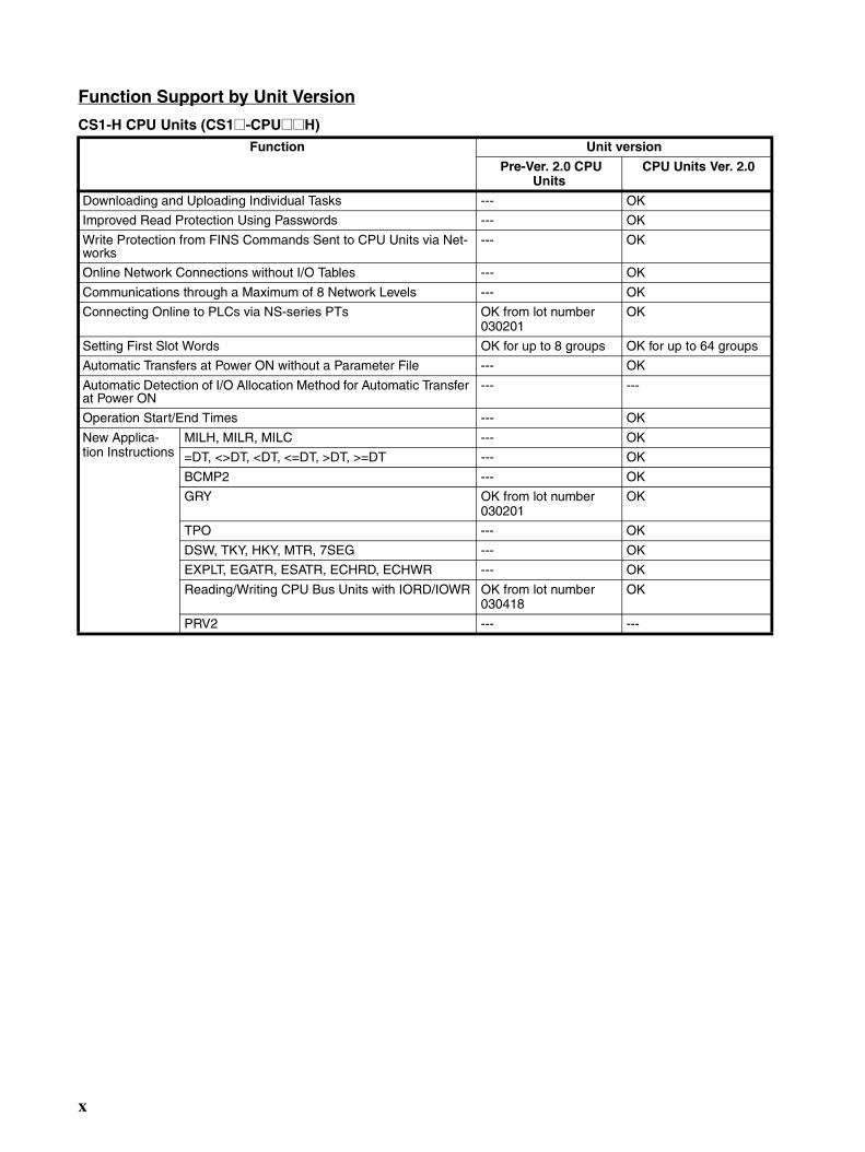
Function Support by Unit Version
CS1-H CPU Units (CS1@-CPU@@H) Function Unit version
Pre-Ver. 2.0 CPU Units
CPU Units Ver. 2.0
Downloading and Uploading Individual Tasks --- OK
Improved Read Protection Using Passwords --- OK
Write Protection from FINS Commands Sent to CPU Units via Net-works
--- OK
Online Network Connections without I/O Tables --- OK
Communications through a Maximum of 8 Network Levels --- OK
Connecting Online to PLCs via NS-series PTs OK from lot number 030201
OK
Setting First Slot Words OK for up to 8 groups OK for up to 64 groups
Automatic Transfers at Power ON without a Parameter File --- OK
Automatic Detection of I/O Allocation Method for Automatic Transfer at Power ON
--- ---
Operation Start/End Times --- OK
New Applica-tion Instructions
MILH, MILR, MILC --- OK
=DT, <>DT, <DT, <=DT, >DT, >=DT --- OK
BCMP2 --- OK
GRY OK from lot number 030201
OK
TPO --- OK
DSW, TKY, HKY, MTR, 7SEG --- OK
EXPLT, EGATR, ESATR, ECHRD, ECHWR --- OK
Reading/Writing CPU Bus Units with IORD/IOWR OK from lot number 030418
OK
PRV2 --- ---
x
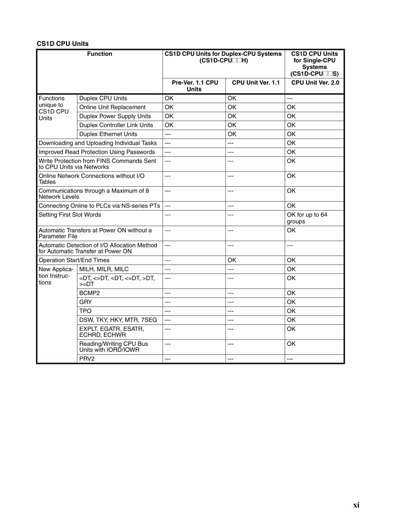
CS1D CPU Units
Function CS1D CPU Units for Duplex-CPU Systems (CS1D-CPU@@H)
CS1D CPU Units for Single-CPU
Systems (CS1D-CPU@@S)
Pre-Ver. 1.1 CPU Units
CPU Unit Ver. 1.1 CPU Unit Ver. 2.0
Functions unique to CS1D CPU Units
Duplex CPU Units OK OK ---
Online Unit Replacement OK OK OK
Duplex Power Supply Units OK OK OK
Duplex Controller Link Units OK OK OK
Duplex Ethernet Units --- OK OK
Downloading and Uploading Individual Tasks --- --- OK
Improved Read Protection Using Passwords --- --- OK
Write Protection from FINS Commands Sent to CPU Units via Networks
--- --- OK
Online Network Connections without I/O Tables
--- --- OK
Communications through a Maximum of 8 Network Levels
--- --- OK
Connecting Online to PLCs via NS-series PTs --- --- OK
Setting First Slot Words --- --- OK for up to 64 groups
Automatic Transfers at Power ON without a Parameter File
--- --- OK
Automatic Detection of I/O Allocation Method for Automatic Transfer at Power ON
--- --- ---
Operation Start/End Times --- OK OK
New Applica-tion Instruc-tions
MILH, MILR, MILC --- --- OK
=DT, <>DT, <DT, <=DT, >DT, >=DT
--- --- OK
BCMP2 --- --- OK
GRY --- --- OK
TPO --- --- OK
DSW, TKY, HKY, MTR, 7SEG --- --- OK
EXPLT, EGATR, ESATR, ECHRD, ECHWR
--- --- OK
Reading/Writing CPU Bus Units with IORD/IOWR
--- --- OK
PRV2 --- --- ---
xi
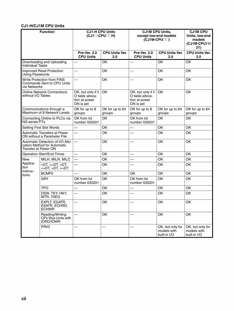
CJ1-H/CJ1M CPU Units
Function CJ1-H CPU Units (CJ1@-CPU@@H)
CJ1M CPU Units,except low-end models
(CJ1M-CPU@@)
CJ1M CPU Units, low-end
models(CJ1M-CPU11/
21)
Pre-Ver. 2.0 CPU Units
CPU Units Ver. 2.0
Pre-Ver. 2.0 CPU Units
CPU Units Ver. 2.0
CPU Units Ver. 2.0
Downloading and Uploading Individual Tasks
--- OK --- OK OK
Improved Read Protection Using Passwords
--- OK --- OK OK
Write Protection from FINS Commands Sent to CPU Units via Networks
--- OK --- OK OK
Online Network Connections without I/O Tables
OK, but only if I/O table alloca-tion at power ON is set
OK OK, but only if I/O table alloca-tion at power ON is set
OK OK
Communications through a Maximum of 8 Network Levels
OK for up to 8 groups
OK for up to 64 groups
OK for up to 8 groups
OK for up to 64 groups
OK for up to 64 groups
Connecting Online to PLCs via NS-series PTs
OK from lot number 030201
OK OK from lot number 030201
OK OK
Setting First Slot Words --- OK --- OK OK
Automatic Transfers at Power ON without a Parameter File
--- OK --- OK OK
Automatic Detection of I/O Allo-cation Method for Automatic Transfer at Power ON
--- OK --- OK OK
Operation Start/End Times --- OK --- OK OK
New Applica-tion Instruc-tions
MILH, MILR, MILC --- OK --- OK OK
=DT, <>DT, <DT, <=DT, >DT, >=DT
--- OK --- OK OK
BCMP2 --- OK OK OK OK
GRY OK from lot number 030201
OK OK from lot number 030201
OK OK
TPO --- OK --- OK OK
DSW, TKY, HKY, MTR, 7SEG
--- OK --- OK OK
EXPLT, EGATR, ESATR, ECHRD, ECHWR
--- OK --- OK OK
Reading/Writing CPU Bus Units with IORD/IOWR
--- OK --- OK OK
PRV2 --- --- --- OK, but only for models with built-in I/O
OK, but only for models with built-in I/O
xii
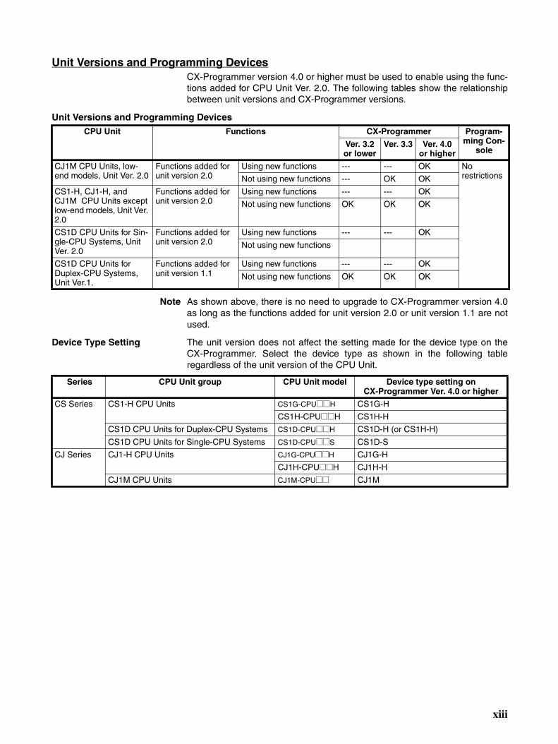
Unit Versions and Programming DevicesCX-Programmer version 4.0 or higher must be used to enable using the func-tions added for CPU Unit Ver. 2.0. The following tables show the relationshipbetween unit versions and CX-Programmer versions.
Unit Versions and Programming Devices
Note As shown above, there is no need to upgrade to CX-Programmer version 4.0as long as the functions added for unit version 2.0 or unit version 1.1 are notused.
Device Type Setting The unit version does not affect the setting made for the device type on theCX-Programmer. Select the device type as shown in the following tableregardless of the unit version of the CPU Unit.
CPU Unit Functions CX-Programmer Program-ming Con-
soleVer. 3.2 or lower
Ver. 3.3 Ver. 4.0 or higher
CJ1M CPU Units, low-end models, Unit Ver. 2.0
Functions added for unit version 2.0
Using new functions --- --- OK No restrictionsNot using new functions --- OK OK
CS1-H, CJ1-H, and CJ1M CPU Units except low-end models, Unit Ver. 2.0
Functions added for unit version 2.0
Using new functions --- --- OK
Not using new functions OK OK OK
CS1D CPU Units for Sin-gle-CPU Systems, Unit Ver. 2.0
Functions added for unit version 2.0
Using new functions --- --- OK
Not using new functions
CS1D CPU Units for Duplex-CPU Systems, Unit Ver.1.
Functions added for unit version 1.1
Using new functions --- --- OK
Not using new functions OK OK OK
Series CPU Unit group CPU Unit model Device type setting on CX-Programmer Ver. 4.0 or higher
CS Series CS1-H CPU Units CS1G-CPU@@H CS1G-H
CS1H-CPU@@H CS1H-H
CS1D CPU Units for Duplex-CPU Systems CS1D-CPU@@H CS1D-H (or CS1H-H)
CS1D CPU Units for Single-CPU Systems CS1D-CPU@@S CS1D-S
CJ Series CJ1-H CPU Units CJ1G-CPU@@H CJ1G-H
CJ1H-CPU@@H CJ1H-H
CJ1M CPU Units CJ1M-CPU@@ CJ1M
xiii
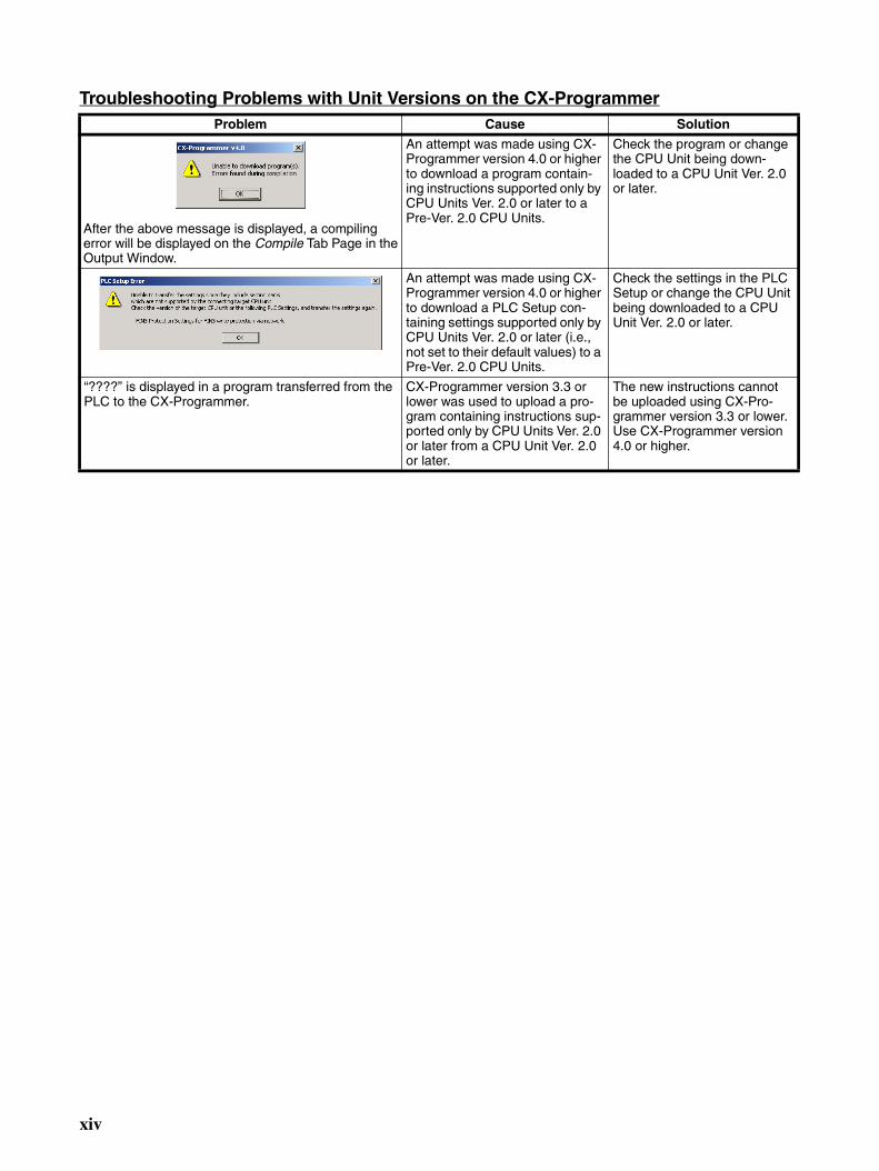
Troubleshooting Problems with Unit Versions on the CX-ProgrammerProblem Cause Solution
After the above message is displayed, a compiling error will be displayed on the Compile Tab Page in the Output Window.
An attempt was made using CX-Programmer version 4.0 or higher to download a program contain-ing instructions supported only by CPU Units Ver. 2.0 or later to a Pre-Ver. 2.0 CPU Units.
Check the program or change the CPU Unit being down-loaded to a CPU Unit Ver. 2.0 or later.
An attempt was made using CX-Programmer version 4.0 or higher to download a PLC Setup con-taining settings supported only by CPU Units Ver. 2.0 or later (i.e., not set to their default values) to a Pre-Ver. 2.0 CPU Units.
Check the settings in the PLC Setup or change the CPU Unit being downloaded to a CPU Unit Ver. 2.0 or later.
“????” is displayed in a program transferred from the PLC to the CX-Programmer.
CX-Programmer version 3.3 or lower was used to upload a pro-gram containing instructions sup-ported only by CPU Units Ver. 2.0 or later from a CPU Unit Ver. 2.0 or later.
The new instructions cannot be uploaded using CX-Pro-grammer version 3.3 or lower. Use CX-Programmer version 4.0 or higher.
xiv
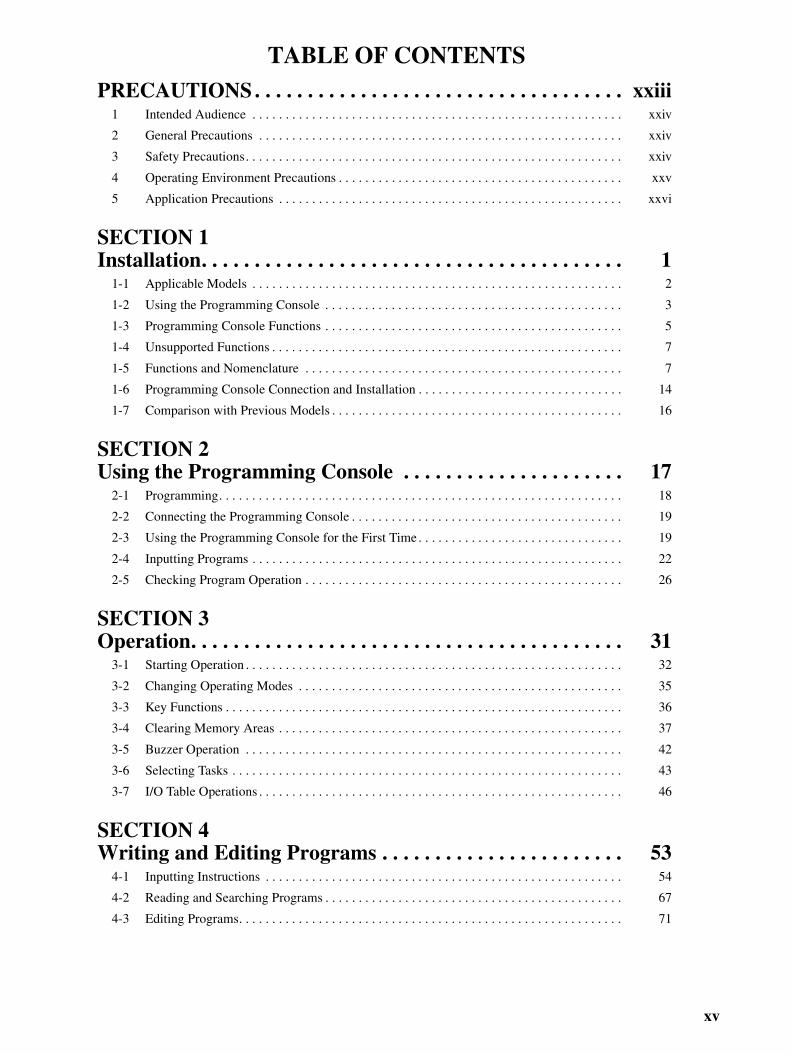
TABLE OF CONTENTS
PRECAUTIONS . . . . . . . . . . . . . . . . . . . . . . . . . . . . . . . . . . . xxiii1 Intended Audience . . . . . . . . . . . . . . . . . . . . . . . . . . . . . . . . . . . . . . . . . . . . . . . . . . . . . . . . xxiv
2 General Precautions . . . . . . . . . . . . . . . . . . . . . . . . . . . . . . . . . . . . . . . . . . . . . . . . . . . . . . . xxiv
3 Safety Precautions. . . . . . . . . . . . . . . . . . . . . . . . . . . . . . . . . . . . . . . . . . . . . . . . . . . . . . . . . xxiv
4 Operating Environment Precautions . . . . . . . . . . . . . . . . . . . . . . . . . . . . . . . . . . . . . . . . . . . xxv
5 Application Precautions . . . . . . . . . . . . . . . . . . . . . . . . . . . . . . . . . . . . . . . . . . . . . . . . . . . . xxvi
SECTION 1Installation. . . . . . . . . . . . . . . . . . . . . . . . . . . . . . . . . . . . . . . . 1
1-1 Applicable Models . . . . . . . . . . . . . . . . . . . . . . . . . . . . . . . . . . . . . . . . . . . . . . . . . . . . . . . . 2
1-2 Using the Programming Console . . . . . . . . . . . . . . . . . . . . . . . . . . . . . . . . . . . . . . . . . . . . . 3
1-3 Programming Console Functions . . . . . . . . . . . . . . . . . . . . . . . . . . . . . . . . . . . . . . . . . . . . . 5
1-4 Unsupported Functions . . . . . . . . . . . . . . . . . . . . . . . . . . . . . . . . . . . . . . . . . . . . . . . . . . . . . 7
1-5 Functions and Nomenclature . . . . . . . . . . . . . . . . . . . . . . . . . . . . . . . . . . . . . . . . . . . . . . . . 7
1-6 Programming Console Connection and Installation . . . . . . . . . . . . . . . . . . . . . . . . . . . . . . . 14
1-7 Comparison with Previous Models . . . . . . . . . . . . . . . . . . . . . . . . . . . . . . . . . . . . . . . . . . . . 16
SECTION 2Using the Programming Console . . . . . . . . . . . . . . . . . . . . . 17
2-1 Programming. . . . . . . . . . . . . . . . . . . . . . . . . . . . . . . . . . . . . . . . . . . . . . . . . . . . . . . . . . . . . 18
2-2 Connecting the Programming Console . . . . . . . . . . . . . . . . . . . . . . . . . . . . . . . . . . . . . . . . . 19
2-3 Using the Programming Console for the First Time . . . . . . . . . . . . . . . . . . . . . . . . . . . . . . . 19
2-4 Inputting Programs . . . . . . . . . . . . . . . . . . . . . . . . . . . . . . . . . . . . . . . . . . . . . . . . . . . . . . . . 22
2-5 Checking Program Operation . . . . . . . . . . . . . . . . . . . . . . . . . . . . . . . . . . . . . . . . . . . . . . . . 26
SECTION 3Operation. . . . . . . . . . . . . . . . . . . . . . . . . . . . . . . . . . . . . . . . . 31
3-1 Starting Operation . . . . . . . . . . . . . . . . . . . . . . . . . . . . . . . . . . . . . . . . . . . . . . . . . . . . . . . . . 32
3-2 Changing Operating Modes . . . . . . . . . . . . . . . . . . . . . . . . . . . . . . . . . . . . . . . . . . . . . . . . . 35
3-3 Key Functions . . . . . . . . . . . . . . . . . . . . . . . . . . . . . . . . . . . . . . . . . . . . . . . . . . . . . . . . . . . . 36
3-4 Clearing Memory Areas . . . . . . . . . . . . . . . . . . . . . . . . . . . . . . . . . . . . . . . . . . . . . . . . . . . . 37
3-5 Buzzer Operation . . . . . . . . . . . . . . . . . . . . . . . . . . . . . . . . . . . . . . . . . . . . . . . . . . . . . . . . . 42
3-6 Selecting Tasks . . . . . . . . . . . . . . . . . . . . . . . . . . . . . . . . . . . . . . . . . . . . . . . . . . . . . . . . . . . 43
3-7 I/O Table Operations . . . . . . . . . . . . . . . . . . . . . . . . . . . . . . . . . . . . . . . . . . . . . . . . . . . . . . . 46
SECTION 4Writing and Editing Programs . . . . . . . . . . . . . . . . . . . . . . . 53
4-1 Inputting Instructions . . . . . . . . . . . . . . . . . . . . . . . . . . . . . . . . . . . . . . . . . . . . . . . . . . . . . . 54
4-2 Reading and Searching Programs . . . . . . . . . . . . . . . . . . . . . . . . . . . . . . . . . . . . . . . . . . . . . 67
4-3 Editing Programs. . . . . . . . . . . . . . . . . . . . . . . . . . . . . . . . . . . . . . . . . . . . . . . . . . . . . . . . . . 71
xv
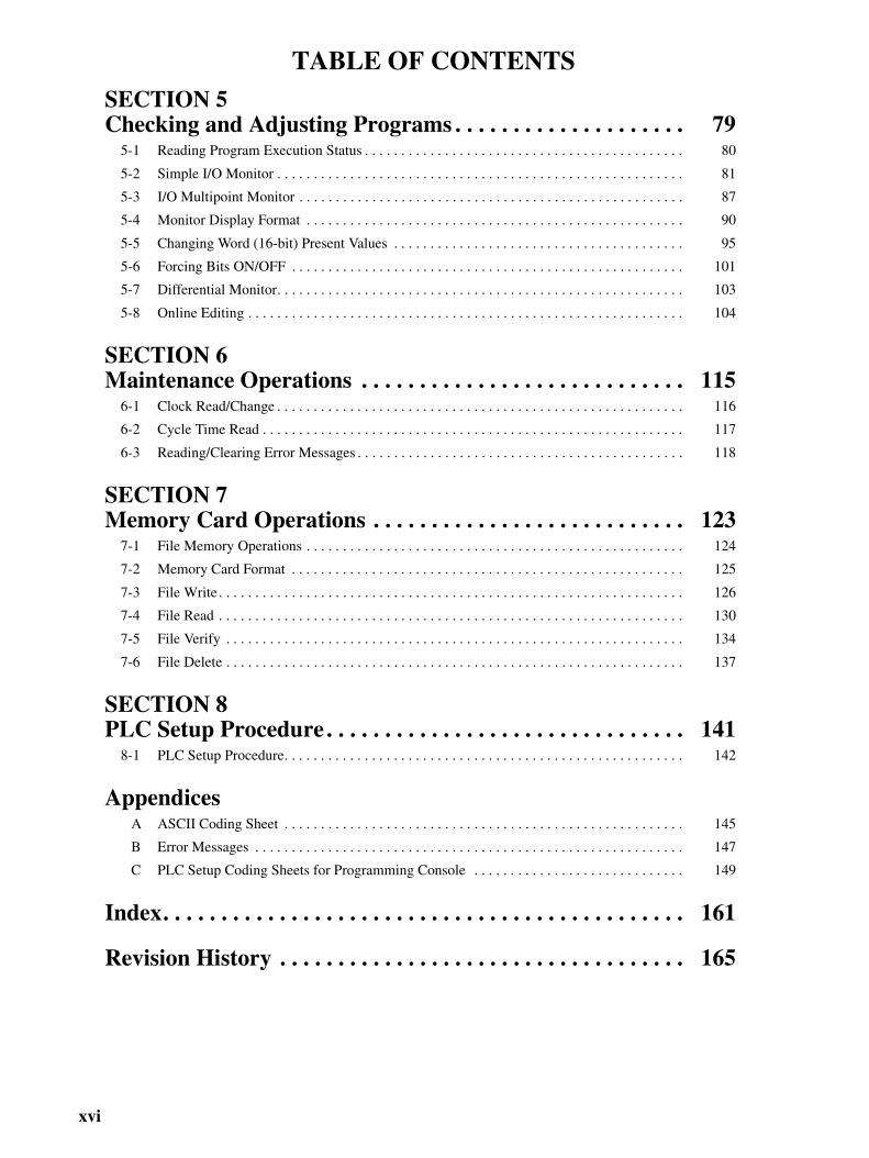
TABLE OF CONTENTS
SECTION 5Checking and Adjusting Programs . . . . . . . . . . . . . . . . . . . . 795-1 Reading Program Execution Status . . . . . . . . . . . . . . . . . . . . . . . . . . . . . . . . . . . . . . . . . . . . 80
5-2 Simple I/O Monitor . . . . . . . . . . . . . . . . . . . . . . . . . . . . . . . . . . . . . . . . . . . . . . . . . . . . . . . . 81
5-3 I/O Multipoint Monitor . . . . . . . . . . . . . . . . . . . . . . . . . . . . . . . . . . . . . . . . . . . . . . . . . . . . . 87
5-4 Monitor Display Format . . . . . . . . . . . . . . . . . . . . . . . . . . . . . . . . . . . . . . . . . . . . . . . . . . . . 90
5-5 Changing Word (16-bit) Present Values . . . . . . . . . . . . . . . . . . . . . . . . . . . . . . . . . . . . . . . . 95
5-6 Forcing Bits ON/OFF . . . . . . . . . . . . . . . . . . . . . . . . . . . . . . . . . . . . . . . . . . . . . . . . . . . . . . 101
5-7 Differential Monitor. . . . . . . . . . . . . . . . . . . . . . . . . . . . . . . . . . . . . . . . . . . . . . . . . . . . . . . . 103
5-8 Online Editing . . . . . . . . . . . . . . . . . . . . . . . . . . . . . . . . . . . . . . . . . . . . . . . . . . . . . . . . . . . . 104
SECTION 6Maintenance Operations . . . . . . . . . . . . . . . . . . . . . . . . . . . . 115
6-1 Clock Read/Change . . . . . . . . . . . . . . . . . . . . . . . . . . . . . . . . . . . . . . . . . . . . . . . . . . . . . . . . 116
6-2 Cycle Time Read . . . . . . . . . . . . . . . . . . . . . . . . . . . . . . . . . . . . . . . . . . . . . . . . . . . . . . . . . . 117
6-3 Reading/Clearing Error Messages . . . . . . . . . . . . . . . . . . . . . . . . . . . . . . . . . . . . . . . . . . . . . 118
SECTION 7Memory Card Operations . . . . . . . . . . . . . . . . . . . . . . . . . . . 123
7-1 File Memory Operations . . . . . . . . . . . . . . . . . . . . . . . . . . . . . . . . . . . . . . . . . . . . . . . . . . . . 124
7-2 Memory Card Format . . . . . . . . . . . . . . . . . . . . . . . . . . . . . . . . . . . . . . . . . . . . . . . . . . . . . . 125
7-3 File Write . . . . . . . . . . . . . . . . . . . . . . . . . . . . . . . . . . . . . . . . . . . . . . . . . . . . . . . . . . . . . . . . 126
7-4 File Read . . . . . . . . . . . . . . . . . . . . . . . . . . . . . . . . . . . . . . . . . . . . . . . . . . . . . . . . . . . . . . . . 130
7-5 File Verify . . . . . . . . . . . . . . . . . . . . . . . . . . . . . . . . . . . . . . . . . . . . . . . . . . . . . . . . . . . . . . . 134
7-6 File Delete . . . . . . . . . . . . . . . . . . . . . . . . . . . . . . . . . . . . . . . . . . . . . . . . . . . . . . . . . . . . . . . 137
SECTION 8PLC Setup Procedure . . . . . . . . . . . . . . . . . . . . . . . . . . . . . . . 141
8-1 PLC Setup Procedure. . . . . . . . . . . . . . . . . . . . . . . . . . . . . . . . . . . . . . . . . . . . . . . . . . . . . . . 142
AppendicesA ASCII Coding Sheet . . . . . . . . . . . . . . . . . . . . . . . . . . . . . . . . . . . . . . . . . . . . . . . . . . . . . . . 145
B Error Messages . . . . . . . . . . . . . . . . . . . . . . . . . . . . . . . . . . . . . . . . . . . . . . . . . . . . . . . . . . . 147
C PLC Setup Coding Sheets for Programming Console . . . . . . . . . . . . . . . . . . . . . . . . . . . . . 149
Index. . . . . . . . . . . . . . . . . . . . . . . . . . . . . . . . . . . . . . . . . . . . . 161
Revision History . . . . . . . . . . . . . . . . . . . . . . . . . . . . . . . . . . . 165
xvi
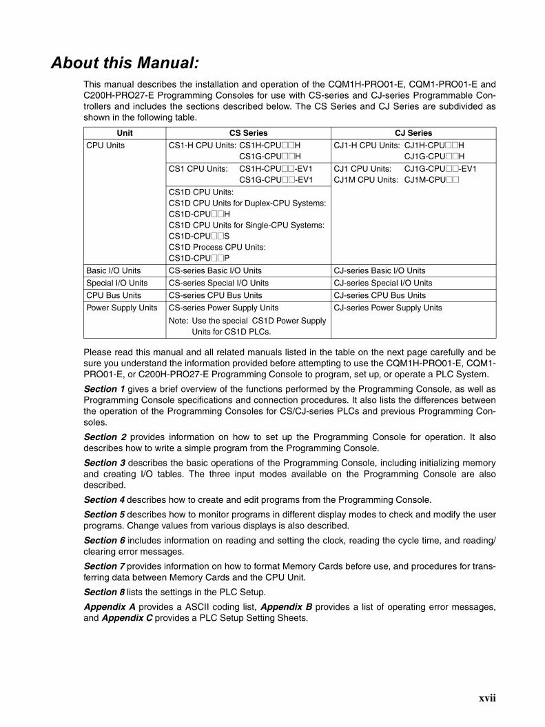
About this Manual:This manual describes the installation and operation of the CQM1H-PRO01-E, CQM1-PRO01-E andC200H-PRO27-E Programming Consoles for use with CS-series and CJ-series Programmable Con-trollers and includes the sections described below. The CS Series and CJ Series are subdivided asshown in the following table.
Please read this manual and all related manuals listed in the table on the next page carefully and besure you understand the information provided before attempting to use the CQM1H-PRO01-E, CQM1-PRO01-E, or C200H-PRO27-E Programming Console to program, set up, or operate a PLC System.
Section 1 gives a brief overview of the functions performed by the Programming Console, as well asProgramming Console specifications and connection procedures. It also lists the differences betweenthe operation of the Programming Consoles for CS/CJ-series PLCs and previous Programming Con-soles.
Section 2 provides information on how to set up the Programming Console for operation. It alsodescribes how to write a simple program from the Programming Console.
Section 3 describes the basic operations of the Programming Console, including initializing memoryand creating I/O tables. The three input modes available on the Programming Console are alsodescribed.
Section 4 describes how to create and edit programs from the Programming Console.
Section 5 describes how to monitor programs in different display modes to check and modify the userprograms. Change values from various displays is also described.
Section 6 includes information on reading and setting the clock, reading the cycle time, and reading/clearing error messages.
Section 7 provides information on how to format Memory Cards before use, and procedures for trans-ferring data between Memory Cards and the CPU Unit.
Section 8 lists the settings in the PLC Setup.
Appendix A provides a ASCII coding list, Appendix B provides a list of operating error messages,and Appendix C provides a PLC Setup Setting Sheets.
Unit CS Series CJ Series
CPU Units CS1-H CPU Units: CS1H-CPU@@HCS1G-CPU@@H
CJ1-H CPU Units: CJ1H-CPU@@HCJ1G-CPU@@H
CS1 CPU Units: CS1H-CPU@@-EV1CS1G-CPU@@-EV1
CJ1 CPU Units: CJ1G-CPU@@-EV1CJ1M CPU Units: CJ1M-CPU@@
CS1D CPU Units:CS1D CPU Units for Duplex-CPU Systems: CS1D-CPU@@HCS1D CPU Units for Single-CPU Systems: CS1D-CPU@@SCS1D Process CPU Units: CS1D-CPU@@P
Basic I/O Units CS-series Basic I/O Units CJ-series Basic I/O Units
Special I/O Units CS-series Special I/O Units CJ-series Special I/O Units
CPU Bus Units CS-series CPU Bus Units CJ-series CPU Bus Units
Power Supply Units CS-series Power Supply Units
Note: Use the special CS1D Power Supply Units for CS1D PLCs.
CJ-series Power Supply Units
xvii

About this Manual, Continued Name Cat. No. Contents
SYSMAC CS/CJ Series Programming Consoles Operation Manual CQM1H-PRO01-E, CQM1-PRO01-E, C200H-PRO27-E
W341 Provides information on how to program and operate CS/CJ-series PLCs using a Programming Console. (This manual)
SYSMAC CS Series CS1G/H-CPU@@-EV1, CS1G/H-CPU@@HProgrammable Controllers Operation Manual
W339 Describes the installation and operation of the CS-series PLCs.
SYSMAC CJ Series CJ1G-CPU@@, CJ1G/H-CPU@@HProgrammable Controllers Operation Manual
W393 Describes the installation and operation of the CJ-series PLCs.
SYSMAC CS Series CS1D-CPU@@H CPU UnitsCS1D-CPU@@S CPU UnitsCS1D-DPL01 Duplex UnitCS1D-PA/PD@@@ Power Supply UnitDuplex System Operation Manual
W405 Describes the installation and operation of the Duplex System based on CS1D CPU Units.
SYSMAC CS/CJ SeriesCS1G/H-CPU@@-EV1, CS1G/H-CPU@@H, CS1D-CPU@@H/S, CJ1G-CPU@@, CJ1G/H-CPU@@HProgrammable Controllers Programming Manual
W394 Describes the ladder diagram programming functions and other functions supported by CS-series and CJ-series PLCs.
SYSMAC CS/CJ SeriesCS1G/H-CPU@@-EV1, CS1G/H-CPU@@H, CS1D-CPU@@H/S, CJ1G-CPU@@, CJ1G/H-CPU@@HProgrammable Controllers Instructions Reference Manual
W340 Describes the ladder diagram programming instructions supported by CS-series and CJ-series PLCs.
SYSMAC CX-Programmer Operation ManualWS02-CXP@@-E
W414 Provides information on how to use the CX-Program-mer, a programming device that supports the CS/CJ-series PLCs, and the CX-Net contained within CX-Pro-grammer.SYSMAC
CX-Programmer Operation ManualWS02-CXP@@-EV4
W425
!WARNING Failure to read and understand the information provided in this manual may result in per-sonal injury or death, damage to the product, or product failure. Please read each sectionin its entirety and be sure you understand the information provided in the section andrelated sections before attempting any of the procedures or operations given.
xviii

Read and Understand this ManualPlease read and understand this manual before using the product. Please consult your OMRON representative if you have any questions or comments.
Warranty and Limitations of Liability
WARRANTY
OMRON's exclusive warranty is that the products are free from defects in materials and workmanship for a period of one year (or other period if specified) from date of sale by OMRON.
OMRON MAKES NO WARRANTY OR REPRESENTATION, EXPRESS OR IMPLIED, REGARDING NON-INFRINGEMENT, MERCHANTABILITY, OR FITNESS FOR PARTICULAR PURPOSE OF THE PRODUCTS. ANY BUYER OR USER ACKNOWLEDGES THAT THE BUYER OR USER ALONE HAS DETERMINED THAT THE PRODUCTS WILL SUITABLY MEET THE REQUIREMENTS OF THEIR INTENDED USE. OMRON DISCLAIMS ALL OTHER WARRANTIES, EXPRESS OR IMPLIED.
LIMITATIONS OF LIABILITY
OMRON SHALL NOT BE RESPONSIBLE FOR SPECIAL, INDIRECT, OR CONSEQUENTIAL DAMAGES, LOSS OF PROFITS OR COMMERCIAL LOSS IN ANY WAY CONNECTED WITH THE PRODUCTS, WHETHER SUCH CLAIM IS BASED ON CONTRACT, WARRANTY, NEGLIGENCE, OR STRICT LIABILITY.
In no event shall the responsibility of OMRON for any act exceed the individual price of the product on which liability is asserted.
IN NO EVENT SHALL OMRON BE RESPONSIBLE FOR WARRANTY, REPAIR, OR OTHER CLAIMS REGARDING THE PRODUCTS UNLESS OMRON'S ANALYSIS CONFIRMS THAT THE PRODUCTS WERE PROPERLY HANDLED, STORED, INSTALLED, AND MAINTAINED AND NOT SUBJECT TO CONTAMINATION, ABUSE, MISUSE, OR INAPPROPRIATE MODIFICATION OR REPAIR.
xix

Application Considerations
SUITABILITY FOR USE
OMRON shall not be responsible for conformity with any standards, codes, or regulations that apply to the combination of products in the customer's application or use of the products.
At the customer's request, OMRON will provide applicable third party certification documents identifying ratings and limitations of use that apply to the products. This information by itself is not sufficient for a complete determination of the suitability of the products in combination with the end product, machine, system, or other application or use.
The following are some examples of applications for which particular attention must be given. This is not intended to be an exhaustive list of all possible uses of the products, nor is it intended to imply that the uses listed may be suitable for the products:
• Outdoor use, uses involving potential chemical contamination or electrical interference, or conditions or uses not described in this manual.
• Nuclear energy control systems, combustion systems, railroad systems, aviation systems, medical equipment, amusement machines, vehicles, safety equipment, and installations subject to separate industry or government regulations.
• Systems, machines, and equipment that could present a risk to life or property.
Please know and observe all prohibitions of use applicable to the products.
NEVER USE THE PRODUCTS FOR AN APPLICATION INVOLVING SERIOUS RISK TO LIFE OR PROPERTY WITHOUT ENSURING THAT THE SYSTEM AS A WHOLE HAS BEEN DESIGNED TO ADDRESS THE RISKS, AND THAT THE OMRON PRODUCTS ARE PROPERLY RATED AND INSTALLED FOR THE INTENDED USE WITHIN THE OVERALL EQUIPMENT OR SYSTEM.
PROGRAMMABLE PRODUCTS
OMRON shall not be responsible for the user's programming of a programmable product, or any consequence thereof.
xx
Disclaimers
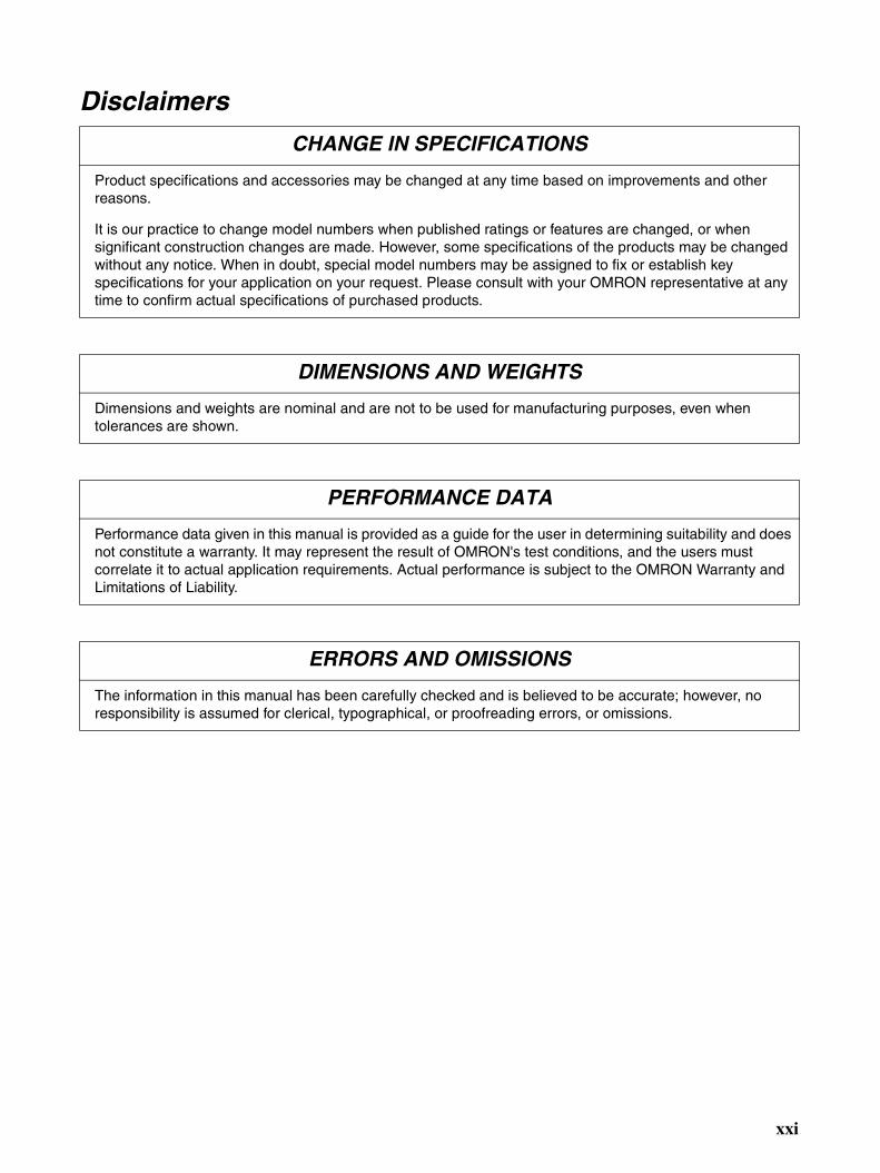
CHANGE IN SPECIFICATIONS
Product specifications and accessories may be changed at any time based on improvements and other reasons.
It is our practice to change model numbers when published ratings or features are changed, or when significant construction changes are made. However, some specifications of the products may be changed without any notice. When in doubt, special model numbers may be assigned to fix or establish key specifications for your application on your request. Please consult with your OMRON representative at any time to confirm actual specifications of purchased products.
DIMENSIONS AND WEIGHTS
Dimensions and weights are nominal and are not to be used for manufacturing purposes, even when tolerances are shown.
PERFORMANCE DATA
Performance data given in this manual is provided as a guide for the user in determining suitability and does not constitute a warranty. It may represent the result of OMRON's test conditions, and the users must correlate it to actual application requirements. Actual performance is subject to the OMRON Warranty and Limitations of Liability.
ERRORS AND OMISSIONS
The information in this manual has been carefully checked and is believed to be accurate; however, no responsibility is assumed for clerical, typographical, or proofreading errors, or omissions.
xxi

PRECAUTIONS
This section provides general precautions for using the Programmable Controller (PLC) and related devices.
The information contained in this section is important for the safe and reliable application of the ProgrammableController. You must read this section and understand the information contained before attempting to set up oroperate a PLC system.
1 Intended Audience . . . . . . . . . . . . . . . . . . . . . . . . . . . . . . . . . . . . . . . . . . . . . xxiv2 General Precautions . . . . . . . . . . . . . . . . . . . . . . . . . . . . . . . . . . . . . . . . . . . . xxiv3 Safety Precautions. . . . . . . . . . . . . . . . . . . . . . . . . . . . . . . . . . . . . . . . . . . . . . xxiv4 Operating Environment Precautions . . . . . . . . . . . . . . . . . . . . . . . . . . . . . . . . xxv5 Application Precautions . . . . . . . . . . . . . . . . . . . . . . . . . . . . . . . . . . . . . . . . . xxvi
xxiii
Intended Audience 1
1 Intended AudienceThis manual is intended for the following personnel, who must also haveknowledge of electrical systems (an electrical engineer or the equivalent).
• Personnel in charge of designing FA systems.
• Personnel in charge of managing FA systems and facilities.
2 General PrecautionsThe user must operate the product according to the performance specifica-tions described in the operation manuals.
Before using the product under conditions which are not described in themanual or applying the product to nuclear control systems, railroad systems,aviation systems, vehicles, combustion systems, medical equipment, amuse-ment machines, safety equipment, and other systems, machines, and equip-ment that may have a serious influence on lives and property if usedimproperly, consult your OMRON representative.
Make sure that the ratings and performance characteristics of the product aresufficient for the systems, machines, and equipment, and be sure to providethe systems, machines, and equipment with double safety mechanisms.
This manual provides information for programming and operating the Unit. Besure to read this manual before attempting to use the Unit and keep this man-ual close at hand for reference during operation.
!WARNING It is extremely important that a PLC and all PLC Units be used for the speci-fied purpose and under the specified conditions, especially in applications thatcan directly or indirectly affect human life. You must consult with your OMRONrepresentative before applying a PLC System to the above-mentioned appli-cations.
3 Safety Precautions
!WARNING Do not attempt to take any Unit apart while the power is being supplied. Doingso may result in electric shock.
!WARNING Do not attempt to disassemble, repair, or modify any Units. Any attempt to doso may result in malfunction, fire, or electric shock.
!Caution The CPU Unit refreshes I/O even when operation has been stopped in PRO-GRAM mode. Always confirm safety before changing data in the output areaallocated to the Output Units or changing data in any memory area allocatedto Special I/O Units or CPU Bus Units using any of the following operations.The loads connected to the Output Units, Special I/O Units, or CPU Bus Unitsmay operate unexpectedly.
• Transferring I/O memory to the CPU Unit using a peripheral device (per-sonal computer software).
• Changing the present value using a peripheral device.
• Force-setting/resetting using a peripheral device.
• Transferring I/O memory files to the CPU Unit from the Memory Card orEM File Memory.
xxiv
Operating Environment Precautions 4
• Transferring I/O memory data from other personal computers or hostcomputers on the network.
!Caution Confirm that the equipment is operating safely before starting actual opera-tion.
!Caution Execute online edit only after confirming that no adverse effects will becaused by extending the cycle time. Otherwise, the input signals may not bereadable.
!Caution Confirm that no adverse effect will occur in the system before executing onlineedit.
4 Operating Environment Precautions
!Caution Do not operate the control system in the following places:
• Locations subject to direct sunlight.
• Locations subject to temperatures or humidity outside the range specifiedin the specifications.
• Locations subject to condensation as the result of severe changes in tem-perature.
• Locations subject to corrosive or flammable gases.
• Locations subject to dust (especially iron dust) or salts.
• Locations subject to exposure to water, oil, or chemicals.
• Locations subject to shock or vibration.
!Caution Take appropriate and sufficient countermeasures when installing systems inthe following locations:
• Locations subject to static electricity or other forms of noise.
• Locations subject to strong electromagnetic fields.
• Locations subject to possible exposure to radioactivity.
• Locations close to power supplies.
!Caution The operating environment of the PLC System can have a large effect on thelongevity and reliability of the system. Improper operating environments canlead to malfunction, failure, and other unforeseeable problems with the PLCSystem. Be sure that the operating environment is within the specified condi-tions at installation and remains within the specified conditions during the lifeof the system.
xxv
Application Precautions 5
5 Application PrecautionsObserve the following precautions when using the PLC System.
!WARNING Always heed these precautions. Failure to abide by the following precautionscould lead to serious or possibly fatal injury.
• Always connect to a class-3 ground (to 100 Ω or less) when installing theUnits. Not connecting to a class-3 ground may result in electric shock.
• Always turn OFF the power supply to the PLC before attempting any ofthe following. Not turning OFF the power supply may result in malfunctionor electric shock.
• Mounting or dismounting I/O Units, CPU Unit, Power Supply Units, In-ner Boards, or any other Units.
• Assembling the Units.
• Setting DIP switches or rotary switches.
• Connecting or wiring the cables.
• Connecting or disconnecting the connectors.
!Caution Failure to abide by the following precautions could lead to faulty operation ofthe PLC or the system, or could damage the PLC or PLC Units. Always heedthese precautions.
• Fail-safe measures must be taken by the customer to ensure safety in theevent of incorrect, missing, or abnormal signals caused by broken signallines, momentary power interruptions, or other causes.
• Interlock circuits, limit circuits, and similar safety measures in external cir-cuits (i.e., not in the Programmable Controller) must be provided by thecustomer.
• Install external breakers and take other safety measures against short-cir-cuiting in external wiring. Insufficient safety measures against short-cir-cuiting may result in burning.
• Be sure that all the mounting screws, terminal screws, and cable connec-tor screws are tightened to the torque specified in the relevant manuals.Incorrect tightening torque may result in malfunction.
• Always use the power supply voltage specified in the operation manuals.An incorrect voltage may result in malfunction or burning.
• Take appropriate measures to ensure that the specified power with therated voltage and frequency is supplied. Be particularly careful in placeswhere the power supply is unstable. An incorrect power supply may resultin malfunction.
• Do not apply voltages to the Input Units in excess of the rated input volt-age. Excess voltages may result in burning.
• Do not apply voltages or connect loads to the Output Units in excess ofthe maximum switching capacity. Excess voltage or loads may result inburning.
• Wire the Unit correctly.
• Mount the Unit only after checking the terminal block completely.
xxvi

Application Precautions 5
• Use crimp terminals for wiring. Do not connect bare stranded wiresdirectly to terminals. Connection of bare stranded wires may result inburning.
• Leave the label attached to the Unit when wiring. Removing the label mayresult in malfunction.
• Remove the label after the completion of wiring to ensure proper heat dis-sipation. Leaving the label attached may result in malfunction.
• Disconnect the functional ground terminal when performing withstandvoltage tests. Not disconnecting the functional ground terminal may resultin burning.
• Check the orientation and polarity of terminal blocks and connectorsbefore connecting them.
• Be sure that the terminal blocks, expansion cables, and other items withlocking devices are properly locked into place. Improper locking mayresult in malfunction.
• Double-check all the wiring before turning ON the power supply. Incorrectwiring may result in burning.
• Check the user program for proper execution before actually running it onthe Unit. Not checking the program may result in an unexpected opera-tion.
• Confirm that no adverse effect will occur in the system before attemptingany of the following. Not doing so may result in an unexpected operation.
• Changing the operating mode of the PLC.
• Force-setting/force-resetting any bit in memory.
• Changing the present value of any word or any set value in memory.
• Transfer any essential data for restarting the PLC, such as data memoryand hold bits to the CPU Unit before restarting the PLC.
• Do not pull on the cables or bend the cables beyond their natural limit.Doing either of these may break the cables.
• Do not place objects on top of the cables. Doing so may break the cables.
• When replacing parts, be sure to confirm that the rating of a new part iscorrect. Not doing so may result in malfunction or burning.
• Before touching the Unit, be sure to first touch a grounded metallic objectin order to discharge any static built-up. Not doing so may result in mal-function or damage.
xxvii


1
SECTION 1Installation
This section describes the Programming Console used with CS/CJ-series PLCs. It includes a brief overview of the functionsperformed by the Programming Console, as well as Programming Console installation procedures.
1-1 Applicable Models . . . . . . . . . . . . . . . . . . . . . . . . . . . . . . . . . . . . . . . . . . . . . 2
1-2 Using the Programming Console . . . . . . . . . . . . . . . . . . . . . . . . . . . . . . . . . . 3
1-3 Programming Console Functions . . . . . . . . . . . . . . . . . . . . . . . . . . . . . . . . . . 5
1-4 Unsupported Functions . . . . . . . . . . . . . . . . . . . . . . . . . . . . . . . . . . . . . . . . . . 7
1-5 Functions and Nomenclature . . . . . . . . . . . . . . . . . . . . . . . . . . . . . . . . . . . . . 7
1-5-1 Nomenclature . . . . . . . . . . . . . . . . . . . . . . . . . . . . . . . . . . . . . . . . . . 8
1-5-2 The Mode Switch and Operating Modes . . . . . . . . . . . . . . . . . . . . . 10
1-5-3 Key Functions . . . . . . . . . . . . . . . . . . . . . . . . . . . . . . . . . . . . . . . . . . 11
1-6 Programming Console Connection and Installation . . . . . . . . . . . . . . . . . . . . 14
1-7 Comparison with Previous Models . . . . . . . . . . . . . . . . . . . . . . . . . . . . . . . . . 16

Applicable Models Section 1-1
1-1 Applicable ModelsApplicable Programming Consoles
Any of the following Programming Consoles can be used with CS/CJ-seriesPLCs: CQM1H-PRO01-E, CQM1-PRO01-E and the C200H-PRO27-E. TheKey Sheet and Connecting Cables listed below are required.
The Programming Console is connected to the peripheral port on the CPUUnit. It cannot be connected to the RS-232C port.
In a CS1D Duplex-CPU System, the Programming Console is connected tothe active CPU Unit.
Applicable CPU Units
Programming Console
Key Sheet Connecting Cables
CQM1H-PRO01-E CS1W-KS001-E 2-m cable included
CQM1-PRO01-E CS1W-CN114 (0.05 m)
C200H-PRO27-E CS1W-CN224 (2.0 m) or CS1W-CN624 (6.0 m)
CS1W-KS001-EKey Sheet Connecting Cable
provided with the CQM1H-PRO01-E
CS/CJ CS/CJ
CS1W-N114 Connecting Cable: 0.05 m
CS/CJ
CS1W-CN224: 2.0 mCS1W-CN624: 6.0 m
CS1W-KS001-EKey Sheet
CS1W-KS001-EKey Sheet
Connecting Cable provided with the CQM1H-PRO01-E
C200H-PRO27-ECQM1-PRO01-ECQM1H-PRO01-E
Series CPU Units Abbreviation in this manual
CS Series CS1H-CPU6@-V1 CS1G-CPU4@-V1
CS1 CPU Unit
CS1H-CPU6@HCS1G-CPU4@H
CS1-H CPU Unit
CS1D-CPU6@HCS1D-CPU@@S
CS1D CPU Unit
CJ Series CJ1G-CPU4@ CJ1 CPU Unit
CJ1H-CPU6@HCJ1G-CPU4@H
CJ1-H CPU Unit
CJ1M-CPU@@ CJ1M CPU Unit
2

Using the Programming Console Section 1-2
Operational Differences for CPU Units
The operation of the Programming Console will vary with the CPU Unit that isconnected as shown in the following table. These are the only differences inProgramming Console operation that vary with the CPU Unit.
1-2 Using the Programming ConsoleProgramming Console The Programming Console for CS/CJ-series PLCs is used to write, to make
on-site adjustments to, and to protect user programs. To create and edit rela-tively large user programs, the CX-Programmer (running on a Windows com-puter) should be used.
Programming Console Features
Programming is started by using the CX-Programmer, a programming andmonitoring software package that runs on a Windows computer, to create theprogram. Programming is completed by debugging the program on the PLC.The Programming Console is used after programming has been completed tochange the operating mode, change sections of the ladder program, monitoroperation, change present values in I/O memory, change the PLC Setup, andread error information. The Programming Console can also be used to trans-fer and verify data between EM File Memory and the PLC.
Operation CS Series CJ Series
CS1 CPU Units
CS1-H CPU Units
CJ1 CPU Units
CJ1-H CPU Units
Operating mode when at startup (when PLC Setup is set to the default setting and the Program-ming Console is not connected)
PROGRAM RUN
Selecting the display language Pin 3 on DIP switch on front panel of CPU Unit
Programming Console key switch
3
Using the Programming Console Section 1-2
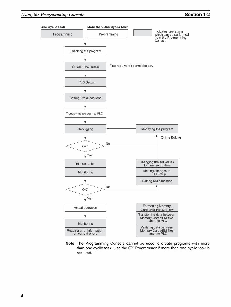
Note The Programming Console cannot be used to create programs with morethan one cyclic task. Use the CX-Programmer if more than one cyclic task isrequired.
Setting DM allocation
Setting DM allocations
Creating I/O tables
Programming
One Cyclic Task More than One Cyclic TaskIndicates operations which can be performed from the Programming Console
Checking the program
PLC Setup
Transferring program to PLC
Debugging
OK?
Trial operation
Actual operation
Modifying the program
Reading error information on current errors
Verifying data between Memory Cards/EM files
and the PLC
Programming
OK?
Monitoring
Monitoring
Changing the set values for timers/counters
Making changes to PLC Setup
Formatting Memory Cards/EM File Memory
Transferring data between Memory Cards/EM files
and the PLC
No
No
Yes
Yes
First rack words cannot be set.
Online Editing
4

Programming Console Functions Section 1-3
1-3 Programming Console FunctionsThe Programming Console performs the following functions.
Operational Settings
Buzzer Operation.
Memory Clear
All Clear
Specifying memory areas not to clear.
Memory Clear
Specifying the first program address to clear. Specifying memory areas not to clear.
Creating/Verifying I/O Tables
I/O Table Create.
I/O Table Verify.
Maintenance
Reading/Clearing Error Messages.
Cycle Time Read.
Ladder Programming
Selecting Tasks
Program Read Setting Addresses
Searching Instruction Search
Bit Search
Program Write Instruction Write
Operand Input
Program Edit Instruction Change
Instruction Insert
Instruction Delete
Operand Change
N.O./N.C. Change
Instruction Variation Change
Timer/Counter SV change
Timer/Counter SV Change 1 (Sets constant or word)
Timer/Counter SV Change 2 (Fine adjustment of constant)
See p42.
See p39.
See p41.See p41.
See p46.See p48.
See p118.
See p117.
See p43.
See p67.
See p68.
See p69.
See p71.
See p72.
See p73.
See p74.
See p74.
See p75.
See p76.
5
Programming Console Functions Section 1-3
Data transfer from PLC to Memory Card
Data transfer from Memory Card to PLC
File Verify
File Delete Memory Card format
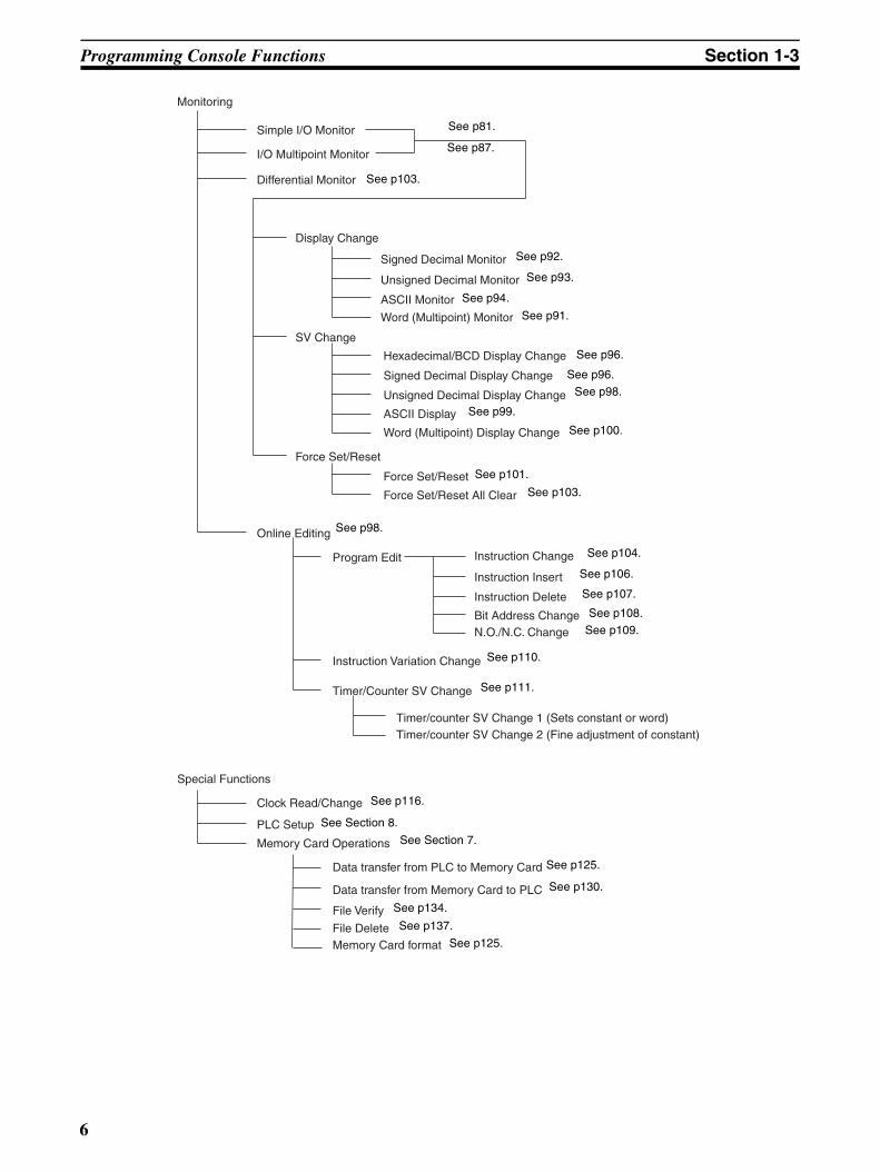
SV Change
Monitoring
Simple I/O Monitor
I/O Multipoint Monitor
Online Editing
Signed Decimal Monitor
Unsigned Decimal Monitor
ASCII Monitor
Word (Multipoint) Monitor
Special Functions
Differential Monitor
Display Change
Hexadecimal/BCD Display Change
Signed Decimal Display Change
Unsigned Decimal Display Change
ASCII Display
Word (Multipoint) Display Change
Force Set/Reset
Force Set/Reset All Clear
Force Set/Reset
Program Edit Instruction Change
Instruction Insert
Instruction Delete
Bit Address ChangeN.O./N.C. Change
Instruction Variation Change
Timer/Counter SV Change
Timer/counter SV Change 1 (Sets constant or word)Timer/counter SV Change 2 (Fine adjustment of constant)
Clock Read/Change
PLC Setup
Memory Card Operations
See p81.
See p87.
See p103.
See p92.
See p93.
See p94.
See p91.
See p96.
See p96.
See p98.
See p99.
See p100.
See p110.
See p111.
See p101.
See p103.
See p104.
See p106.
See p107.
See p108.
See p109.
See p116.
See Section 8.
See Section 7.
See p125.
See p130.
See p134.
See p137.
See p125.
See p98.
6
Unsupported Functions Section 1-4
1-4 Unsupported FunctionsThe following operations cannot be performed on the Programming Console.Use the CX-Programmer to perform these operations.
• Creating several cyclic tasks.
• Checking programs.
• Operations related to Communications Units.
• Displaying error history information.
• Setting the first rack words.
• Data tracing.
• Setting and clearing program read protection.
1-5 Functions and NomenclatureHandling Precautions Although the Programming Console does not require regular maintenance,
observe the following precautions.
• Do not subject the Programming Console to excessive shock duringtransportation or operation. Handle the keypad and the LCD display withcare.
• The C200H-PRO27-E Programming Console has two connectors. Useonly one of them at a time.
• Connect the cable to the Programming Console firmly until you hear itclick into place, indicating that the cable is locked firmly in place.
• When removing the cable, hold the levers on both sides of the cable,release the lock, and pull the cable out.
• Do not pull or twist the cable with excessive force.
• The ambient operating temperature is 0 to 55°C. Be careful that this tem-perature is not exceeded when the Programming Console is usedmounted to a panel.
Operating Environment Do not install or operate the Programming Console in any of the followinglocations.
• Locations subject to temperatures or humidities outside the ranges speci-fied in the specifications.
• Locations directly subject to excessive shock.
• Locations subject to strong magnetic fields or electromagnetic waves.
• Locations subject to direct sunlight.
7
Functions and Nomenclature Section 1-5
1-5-1 Nomenclature
C200H-PRO27-E
FUNA
SFTB
NOTC
SHIFTF
*EM
KWR/LR
. IR+
D. IR
. −IR
JTR
DR
EIR
TN
GAND
ST
HOR
TK
ICNT
AR
LHR
AA
MLD
AC
NOUT TIM
O
EM
PDM
CH
Q*DM
CONT
R#
77
88
99
*EM_
SEM_/EXT CHG
T
CF
USRCH
44
E5
5
F6
6
SETV
DELW
MONX
11
B2
2
C3
3
DRESET
Y
INSZ
↑
↓WRITEVRFYCLRTEXT
!00
A
FUNA
SFTB
NOTC
SHIFTF
*EM
KWR/LR
. IR+
D. IR
. −IR
JTR
DR
EIR
TN
GAND
ST
HOR
TK
ICNT
AR
LHR
AA
MLD
AC
NOUT TIM
O
EM
PDM
CH
Q*DM
CONT
R#
77
88
99
*EM_
SEM_/EXT CHG
T
CF
USRCH
44
E5
5
F6
6
SETV
DELW
MONX
11
B2
2
C3
3
DRESET
Y
INSZ
↑
↓WRITEVRFYCLRTEXT
!00
A
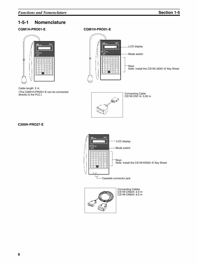
Cable length: 2 m(The CQM1H-PRO01-E can be connected directly to the PLC.)
CQM1H-PRO01-E CQM1H-PRO01-E
LCD display
Mode switch
KeysNote: Install the CS1W-JS001-E Key Sheet
Connecting CableCS1W-CN114: 0.05 m
FUNA
SFTB
NOTC
SHIFTF
*EM
KWR/LR
. IR+
D. IR
. −IR
JTR
DR
EIR
TN
GAND
ST
HOR
TK
ICNT
AR
LHR
AA
MLD
AC
NOUT TIM
O
EM
PDM
CH
Q*DM
CONT
R#
77
88
99
*EM_
SEM_/EXT CHG
T
CF
USRCH
44
E5
5
F6
6
SETV
DELW
MONX
11
B2
2
C3
3
DRESET
Y
INSZ
↑
↓WRITEVRFYCLRTEXT
!00
A
KeysNote: Install the CS1W-KS001-E Key Sheet
Connecting CablesCS1W-CN224: 2.0 mCS1W-CN624: 6.0 m
Mode switch
LCD display
Cassette connector jack
8
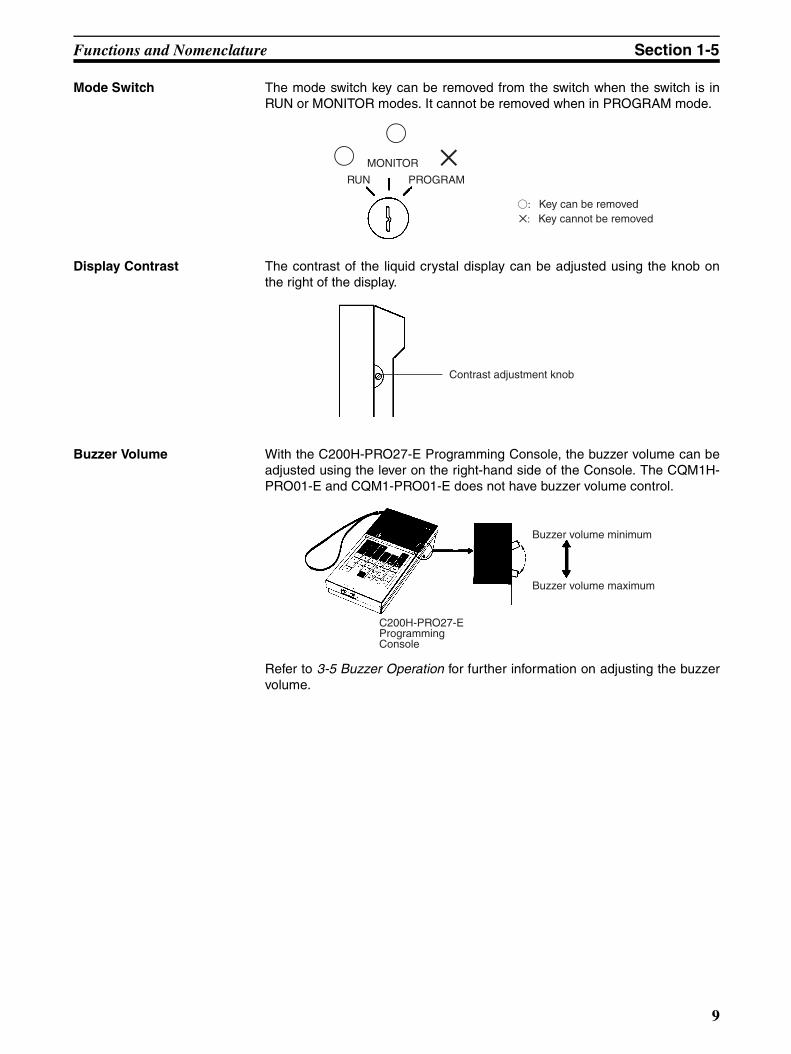
Functions and Nomenclature Section 1-5
Mode Switch The mode switch key can be removed from the switch when the switch is inRUN or MONITOR modes. It cannot be removed when in PROGRAM mode.
Display Contrast The contrast of the liquid crystal display can be adjusted using the knob onthe right of the display.
Buzzer Volume With the C200H-PRO27-E Programming Console, the buzzer volume can beadjusted using the lever on the right-hand side of the Console. The CQM1H-PRO01-E and CQM1-PRO01-E does not have buzzer volume control.
Refer to 3-5 Buzzer Operation for further information on adjusting the buzzervolume.
f: Key can be removed : Key cannot be removed
RUN
MONITOR
PROGRAM
f
f
Contrast adjustment knob
Buzzer volume minimum
Buzzer volume maximum
C200H-PRO27-EProgramming Console
9

Functions and Nomenclature Section 1-5
1-5-2 The Mode Switch and Operating ModesThe relation between the operating mode of the CPU Unit and the modeswitch is as follows:
Startup Operating Mode The operating mode of the CPU Unit when the power is turned ON dependson the status of address 81 in the PLC Setup (Startup Mode) and the connec-tion status of peripheral devices.
Key operation Operating mode
Function
PROGRAM mode
The CPU Unit is stopped. Programming opera-tions, such as writing or changing programs, clearing memory, and checking the program, can be performed.
MONITOR mode
The CPU Unit is operating and I/O processing is being performed. In this mode, CPU Unit operation can be monitored and functions such as forcing bits ON/OFF, changing timer/counter SV/PC, changing word data PVs, and online editing can be used. This mode is often used for making program adjustments and for trial system operations.
RUN mode Used for normal operation of the CPU Unit. The operating status of the CPU Unit can be monitored in this mode, but functions such as forcing bits ON/OFF and changing PVs and SVs cannot be performed.
RUNMONITOR
PROGRAM
RUNMONITOR
PROGRAM
RUNMONITOR
PROGRAM
Startup Mode setting in PLC Setup (address 81)
Peripheral device Startup operating mode
PRCN: Mode set on Pro-gramming Console’s mode switch
Nothing connected CS1 CPU Unit: PROGRAM mode
CJ1/CJ1-H/CS1-H CPU Unit: RUN mode
Programming Con-sole connected
The mode set on the mode switch on the Programming Console
Peripheral device other than Pro-gramming Con-sole connected
CS1 CPU Unit: PROGRAM mode
CJ1/CJ1-H/CS1-H CPU Unit: RUN mode
PRG: PROGRAM mode Not relevant PROGRAM mode
MON: MONITOR mode Not relevant MONITOR mode
RUN: RUN mode Not relevant RUN mode
10
Functions and Nomenclature Section 1-5
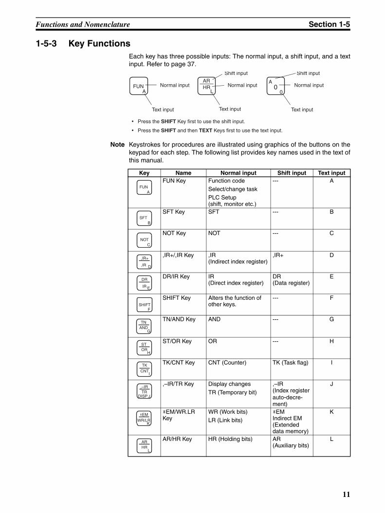
1-5-3 Key FunctionsEach key has three possible inputs: The normal input, a shift input, and a textinput. Refer to page 37.
Note Keystrokes for procedures are illustrated using graphics of the buttons on thekeypad for each step. The following list provides key names used in the text ofthis manual.
Normal input
Shift input
• Press the SHIFT Key first to use the shift input.
• Press the SHIFT and then TEXT Keys first to use the text input.
Text input
Shift input
Normal input Normal input
Text input Text input
FUNA
HRL
AR0
A
0
Key Name Normal input Shift input Text inputFUN Key Function code
Select/change taskPLC Setup (shift, monitor etc.)
--- A
SFT Key SFT --- B
NOT Key NOT --- C
,IR+/,IR Key ,IR(Indirect index register)
,IR+ D
DR/IR Key IR(Direct index register)
DR(Data register)
E
SHIFT Key Alters the function of other keys.
--- F
TN/AND Key AND --- G
ST/OR Key OR --- H
TK/CNT Key CNT (Counter) TK (Task flag) I
,–IR/TR Key Display changes
TR (Temporary bit)
,–IR(Index register auto-decre-ment)
J
*EM/WR.LR Key
WR (Work bits)LR (Link bits)
*EMIndirect EM (Extended data memory)
K
AR/HR Key HR (Holding bits) AR(Auxiliary bits)
L
FUNA
SFTB
NOTC
,IR+
,IR D
DR
IR E
SHIFTF
TNAND
G
STOR
H
TKCNT
I
,–IRTR
JDISP
*EMWR/LR
K
ARHR
L
11

Functions and Nomenclature Section 1-5
AA/LD Key LD --- M
AC/OUT Key OUT --- N
TIM Key TIM (Timer) --- O
EM/DM Key DM (Data memory) EM(Data memory of current bank)
P
CH/*DM Key *DM (Indirect data memory)
CIO word Q
CONT/# Key #Constant(Binary or BCD)
Operand(Bit address)
R
*EM_/EM_.EXT Key
EM_(Expansion Data Mem-ory including bank number)EXT (memory all clear)
*EM (indirect address)
S
CHG Key CHG(Changes to SVs, timer/counter etc.)
--- T
CF/SRCH Key SRCH CF(Condition Flag)
U
SET Key SET OFF-ON dif-ferentiationForce Reset
V
DEL Key DEL (Delete) --- W
MON Key MON(Simple I/O Monitor, I/O Multipoint Monitor, Memory area)
--- X
RESET Key RESET ON-OFF dif-ferentiationForce Reset
Y
INS Key INS (Insert) --- Z
TEXT/! Key !(Immediate refresh)
Alphanumeric input mode
---
CLR Key Clear valuesReturn to previous value
--- Returns to the normal input mode.
VRFY Key VRFY (Verify) --- ---
WRITE Key WRITE --- ---
Key Name Normal input Shift input Text input
AALD
M
ACOUT
N
TIMO
EMDM
P
CH*DM
Q
CONT#
R
*EM_EM_/EXT
S
CHGT
CFSRCH
U
VSET
DELW
MONX
RESETY
INSZ
TEXT!
CLR
VRFY
WRITE
12
Functions and Nomenclature Section 1-5
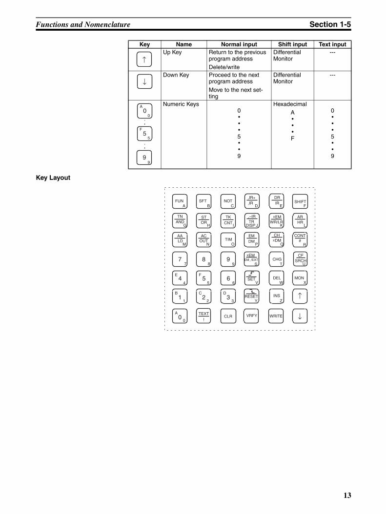
Key Layout
Up Key Return to the previous program addressDelete/write
Differential Monitor
---
Down Key Proceed to the next program address
Move to the next set-ting
Differential Monitor
---
Numeric Keys0•••5••9
HexadecimalA•••F
0•••5••9
Key Name Normal input Shift input Text input
↑
↓
A0
0
F5
5
99
ARHR
L
INSZ
CLR
SHIFTF
NOTC
B1
1
C2
2
D3
3
A0
0↓
↑
F5
56
6
WRITE
TIMO
E4
4
77
88
TKCNT
I
99
SFTB
,IR+,IR
D
STOR
H
TNAND
G
ACOUT
N
*EM_EM_/EXT
S
VRFYTEXT
!
FUNA
VSET
RESETY
MONDEL
CHG
CH*DM
*EMWR/LR
EMDM
CFSRCH
U
,–IRTR
DRIR
CONT#
AALD
E
J K
M P Q R
T
W X
DISP
13
Programming Console Connection and Installation Section 1-6
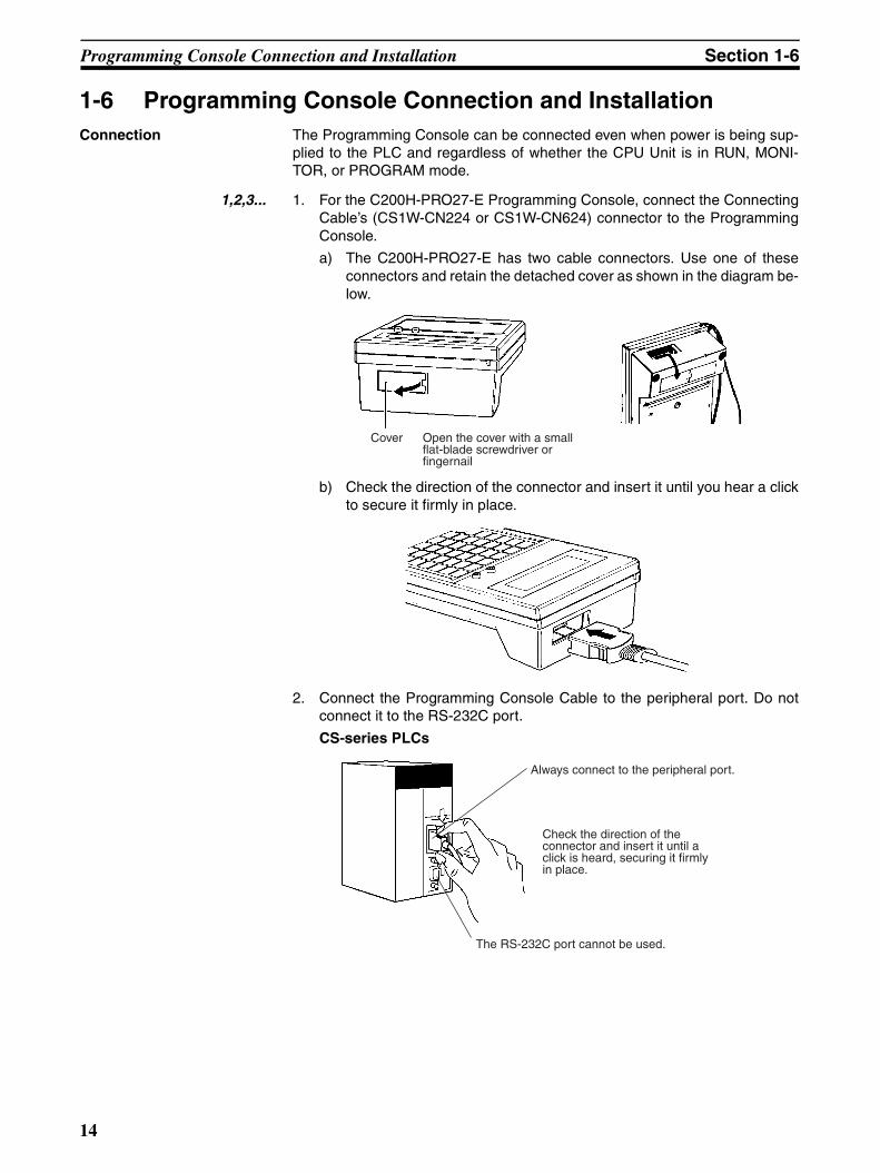
1-6 Programming Console Connection and InstallationConnection The Programming Console can be connected even when power is being sup-
plied to the PLC and regardless of whether the CPU Unit is in RUN, MONI-TOR, or PROGRAM mode.
1,2,3... 1. For the C200H-PRO27-E Programming Console, connect the ConnectingCable’s (CS1W-CN224 or CS1W-CN624) connector to the ProgrammingConsole.
a) The C200H-PRO27-E has two cable connectors. Use one of theseconnectors and retain the detached cover as shown in the diagram be-low.
b) Check the direction of the connector and insert it until you hear a clickto secure it firmly in place.
2. Connect the Programming Console Cable to the peripheral port. Do notconnect it to the RS-232C port.
CS-series PLCs
Cover Open the cover with a small flat-blade screwdriver or fingernail
Always connect to the peripheral port.
Check the direction of the connector and insert it until a click is heard, securing it firmly in place.
The RS-232C port cannot be used.
14

Programming Console Connection and Installation Section 1-6
CJ-series PLCs
3. To disconnect the connector, squeeze the lock release levers on the sidesand pull the connector straight out.
Panel Mounting Use the C200H-PRO27-E Programming Console when the ProgrammingConsole needs to be mounted to a panel. Follow the instructions below formounting the Console to a panel. (The C200H-ATT01 Mounting Bracket issold separately.)
When mounting the Console to a panel, allow enough space for the cables.
Check the direction of the connector. Squeeze in on the sides of the
connector and then insert it.
Lock release lever
186+1.1-0
92+0.8-0
Mounting Bracket
Two screws
Panel thickness: 1.0 to 3.2 mm
Mounting hole dimensions (DIN43700 standards)
37
15
About 70 mm is required.
At least 80 mm is required.
Either connector may be used.
15
Comparison with Previous Models Section 1-7
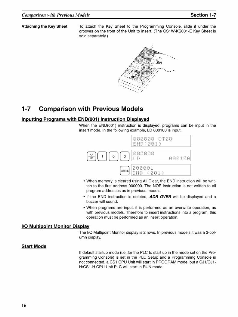
Attaching the Key Sheet To attach the Key Sheet to the Programming Console, slide it under thegrooves on the front of the Unit to insert. (The CS1W-KS001-E Key Sheet issold separately.)
1-7 Comparison with Previous Models
Inputting Programs with END(001) Instruction DisplayedWhen the END(001) instruction is displayed, programs can be input in theinsert mode. In the following example, LD 000100 is input.
• When memory is cleared using All Clear, the END instruction will be writ-ten to the first address 000000. The NOP instruction is not written to allprogram addresses as in previous models.
• If the END instruction is deleted, ADR OVER will be displayed and abuzzer will sound.
• When programs are input, it is performed as an overwrite operation, aswith previous models. Therefore to insert instructions into a program, thisoperation must be performed as an insert operation.
I/O Multipoint Monitor DisplayThe I/O Multipoint Monitor display is 2 rows. In previous models it was a 3-col-umn display.
Start ModeIf default startup mode (i.e.,for the PLC to start up in the mode set on the Pro-gramming Console) is set in the PLC Setup and a Programming Console isnot connected, a CS1 CPU Unit will start in PROGRAM mode, but a CJ1/CJ1-H/CS1-H CPU Unit PLC will start in RUN mode.
000000 CT00END(001)
AALD
1 0 0000000LD 000100
WRITE000001END (001)
16
17
SECTION 2Using the Programming Console
This section provides information on how to setup the Programming Console for operation. It also describes how to writea simple program from the Programming Console.
2-1 Programming. . . . . . . . . . . . . . . . . . . . . . . . . . . . . . . . . . . . . . . . . . . . . . . . . . 18
2-2 Connecting the Programming Console . . . . . . . . . . . . . . . . . . . . . . . . . . . . . . 19
2-3 Using the Programming Console for the First Time . . . . . . . . . . . . . . . . . . . . 19
2-4 Inputting Programs . . . . . . . . . . . . . . . . . . . . . . . . . . . . . . . . . . . . . . . . . . . . . 22
2-5 Checking Program Operation . . . . . . . . . . . . . . . . . . . . . . . . . . . . . . . . . . . . . 26
Programming Section 2-1
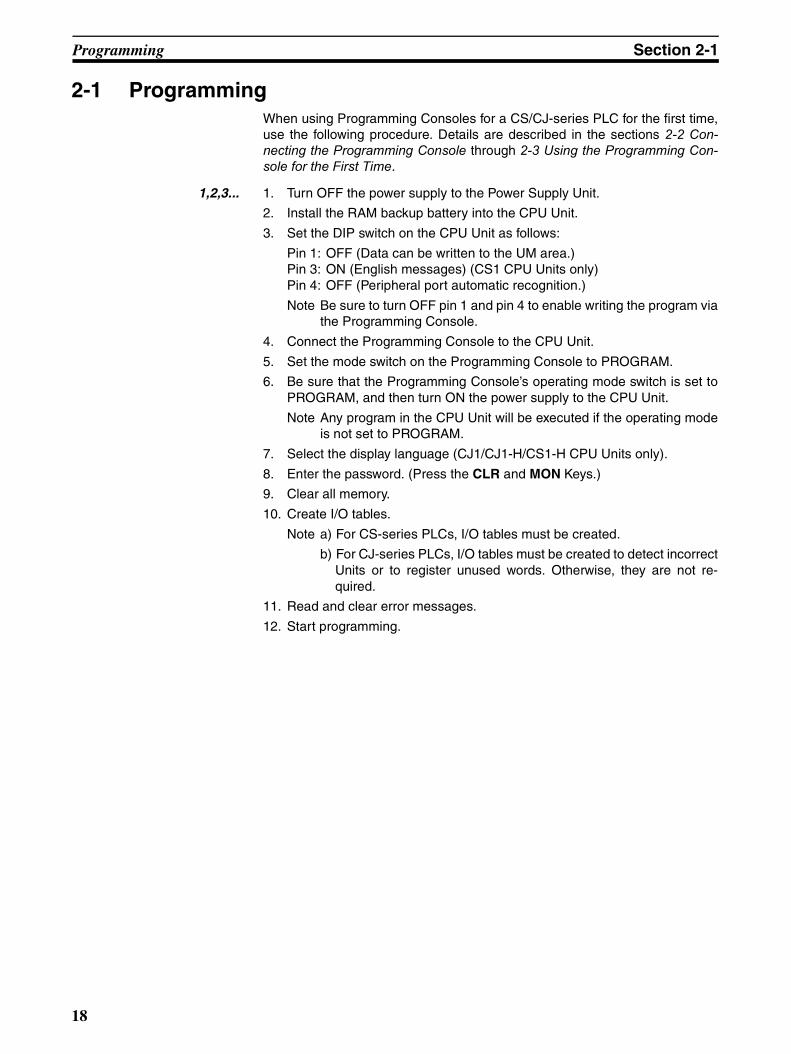
2-1 ProgrammingWhen using Programming Consoles for a CS/CJ-series PLC for the first time,use the following procedure. Details are described in the sections 2-2 Con-necting the Programming Console through 2-3 Using the Programming Con-sole for the First Time.
1,2,3... 1. Turn OFF the power supply to the Power Supply Unit.
2. Install the RAM backup battery into the CPU Unit.
3. Set the DIP switch on the CPU Unit as follows:
Pin 1: OFF (Data can be written to the UM area.)Pin 3: ON (English messages) (CS1 CPU Units only)Pin 4: OFF (Peripheral port automatic recognition.)
Note Be sure to turn OFF pin 1 and pin 4 to enable writing the program viathe Programming Console.
4. Connect the Programming Console to the CPU Unit.
5. Set the mode switch on the Programming Console to PROGRAM.
6. Be sure that the Programming Console’s operating mode switch is set toPROGRAM, and then turn ON the power supply to the CPU Unit.
Note Any program in the CPU Unit will be executed if the operating modeis not set to PROGRAM.
7. Select the display language (CJ1/CJ1-H/CS1-H CPU Units only).
8. Enter the password. (Press the CLR and MON Keys.)
9. Clear all memory.
10. Create I/O tables.
Note a) For CS-series PLCs, I/O tables must be created.
b) For CJ-series PLCs, I/O tables must be created to detect incorrectUnits or to register unused words. Otherwise, they are not re-quired.
11. Read and clear error messages.
12. Start programming.
18

Connecting the Programming Console Section 2-2
2-2 Connecting the Programming ConsoleThe Programming Console can be connected even when power is being sup-plied to the PLC and regardless of whether the CPU Unit is in RUN, MONITOR,or PROGRAM mode.
Note Always connect the Programming Console Cable into the peripheral port. Donot connect it to the RS-232C port.
2-3 Using the Programming Console for the First TimeWhen using the Programming Console for the first time, perform the followingprocedure.
Note Keystrokes for procedures are illustrated using graphics of the keypad buttonsfor each step. A list of key names used in the text is provided in Section 1Installation on page 11.
1,2,3... 1. Make sure that the mode switch is set to PROGRAM, and then turn ON thepower supply to the Power Supply Unit.
Insert a small flat-blade screwdriver into the opening at the top of the Console and pull forwards.
Connect by pressing the connector tab in place.
Check the direction of the connector.
CS-series
Check the direction of the connector. Squeeze in on the sides of the
connector and then insert it.
CJ-series
RUNMONITOR
PROGRAM
19
Using the Programming Console for the First Time Section 2-3
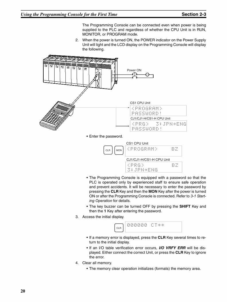
The Programming Console can be connected even when power is beingsupplied to the PLC and regardless of whether the CPU Unit is in RUN,MONITOR, or PROGRAM mode.
2. When the power is turned ON, the POWER indicator on the Power SupplyUnit will light and the LCD display on the Programming Console will displaythe following.
• Enter the password.
• The Programming Console is equipped with a password so that thePLC is operated only by experienced staff to ensure safe operationand prevent accidents. It will be necessary to enter the password bypressing the CLR Key and then the MON Key after the power is turnedON or after the Programming Console is connected. Refer to 3-1 Start-ing Operation for details.
• The key buzzer can be turned OFF by pressing the SHIFT Key andthen the 1 Key after entering the password.
3. Access the initial display.
• If a memory error is displayed, press the CLR Key several times to re-turn to the initial display.
• If an I/O table verification error occurs, I/O VRFY ERR will be dis-played. Either connect the correct Unit, or press the CLR Key to ignorethe error.
4. Clear all memory.
• The memory clear operation initializes (formats) the memory area.
<PROGRAM>
PASSWORD!
Power ON
<PRG> 3:JPN~ENG
PASSWORD!
CS1 CPU Unit
CJ1/CJ1-H/CS1-H CPU Unit
CLR MON <PROGRAM> BZ
CS1 CPU Unit
<PRG> BZ 3:JPN~ENG
CJ1/CJ1-H/CS1-H CPU Unit
CLR000000 CT**
20
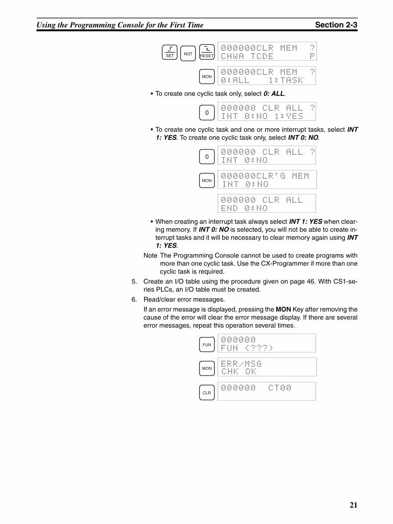
Using the Programming Console for the First Time Section 2-3
• To create one cyclic task only, select 0: ALL.
• To create one cyclic task and one or more interrupt tasks, select INT1: YES. To create one cyclic task only, select INT 0: NO.
• When creating an interrupt task always select INT 1: YES when clear-ing memory. If INT 0: NO is selected, you will not be able to create in-terrupt tasks and it will be necessary to clear memory again using INT1: YES.
Note The Programming Console cannot be used to create programs withmore than one cyclic task. Use the CX-Programmer if more than onecyclic task is required.
5. Create an I/O table using the procedure given on page 46. With CS1-se-ries PLCs, an I/O table must be created.
6. Read/clear error messages.
If an error message is displayed, pressing the MON Key after removing thecause of the error will clear the error message display. If there are severalerror messages, repeat this operation several times.
SET NOT RESET
000000CLR MEM ?CHWA TCDE P
MON000000CLR MEM ?0:ALL 1:TASK
0000000 CLR ALL ?INT 0:NO 1:YES
0000000 CLR ALL ?INT 0:NO
MON000000CLR'G MEMINT 0:NO
000000 CLR ALLEND 0:NO
FUN000000FUN (???)
MONERR/MSGCHK OK
CLR000000 CT00
21
Inputting Programs Section 2-4
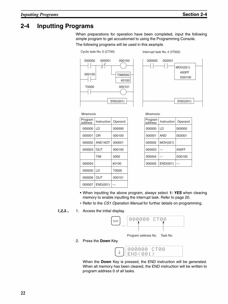
2-4 Inputting ProgramsWhen preparations for operation have been completed, input the followingsimple program to get accustomed to using the Programming Console.
The following programs will be used in this example.
• When inputting the above program, always select 1: YES when clearingmemory to enable inputting the interrupt task. Refer to page 20.
• Refer to the CS1 Operation Manual for further details on programming.
1,2,3... 1. Access the initial display.
…
2. Press the Down Key.
When the Down Key is pressed, the END instruction will be generated.When all memory has been cleared, the END instruction will be written toprogram address 0 of all tasks.
Cyclic task No. 0 (CT00)
Mnemonic
Operand
Interrupt task No. 2 (IT002)
Mnemonic
TIM0000
#0100
000100000001000000
000100
T0000 000101
END(001)
002001000000
END(001)
MOV(021)
#00FF
D00100
000000 LD 000000
000003 OUT 000100
000001 OR 000100
000002 AND NOT 000001
TIM 0000
000004 #0100
000007 END(001) ---
000005 LD T0000
000006 OUT 000101
000000 LD 000000
000003 --- #00FF
000001 AND 002001
000002 MOV(021)
000004 --- D00100
000005 END(001) ---
InstructionProgram address OperandInstruction
Program address
CLR
Program address No.
000000 CT00
Task No.
↓000000 CT00END(001)
22
Inputting Programs Section 2-4
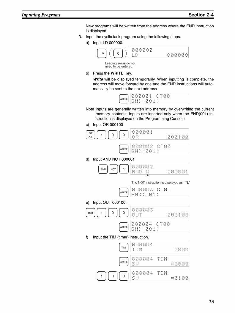
New programs will be written from the address where the END instructionis displayed.
3. Input the cyclic task program using the following steps.
a) Input LD 000000.
b) Press the WRITE Key.
Write will be displayed temporarily. When inputting is complete, theaddress will move forward by one and the END instructions will auto-matically be sent to the next address.
Note Inputs are generally written into memory by overwriting the currentmemory contents. Inputs are inserted only when the END(001) in-struction is displayed on the Programming Console.
c) Input OR 000100
d) Input AND NOT 000001
e) Input OUT 000100.
f) Input the TIM (timer) instruction.
0000000LD 000000
Leading zeros do not need to be entered.
LD
WRITE000001 CT00END(001)
ST
OR1 0 0
000001OR 000100
WRITE000002 CT00END(001)
AND NOT 1 000002AND N 000001
The NOT instruction is displayed as "N."
WRITE000003 CT00END(001)
OUT 1 0 0000003OUT 000100
WRITE000004 CT00END(001)
TIM000004TIM 0000
WRITE000004 TIMSV #0000
1 0 0000004 TIMSV #0100
23
Inputting Programs Section 2-4
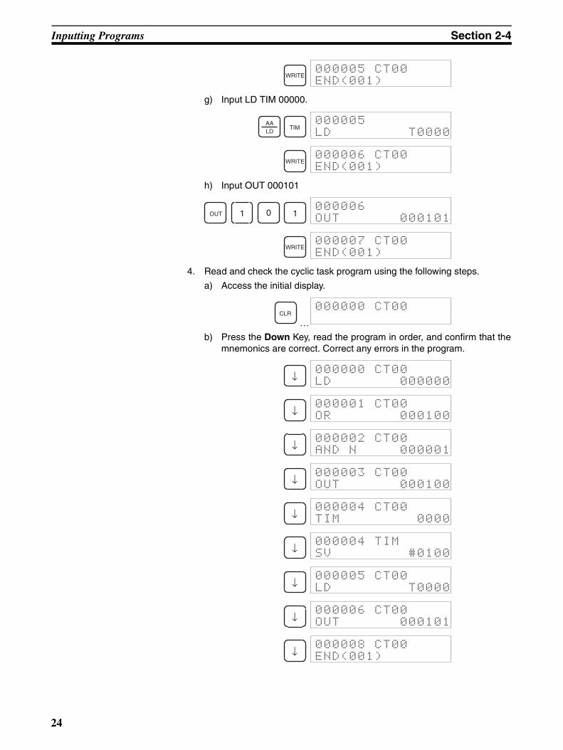
g) Input LD TIM 00000.
h) Input OUT 000101
4. Read and check the cyclic task program using the following steps.
a) Access the initial display.
…b) Press the Down Key, read the program in order, and confirm that the
mnemonics are correct. Correct any errors in the program.
WRITE000005 CT00END(001)
AALD
TIM000005LD T0000
WRITE000006 CT00END(001)
OUT 1 0 1000006OUT 000101
WRITE000007 CT00END(001)
CLR000000 CT00
↓000000 CT00LD 000000
↓000001 CT00OR 000100
↓000002 CT00AND N 000001
↓000003 CT00OUT 000100
↓000004 CT00TIM 0000
↓000004 TIMSV #0100
↓000005 CT00LD T0000
↓000006 CT00OUT 000101
↓000008 CT00END(001)
24

Inputting Programs Section 2-4
5. Switch to interrupt task using the following steps.
a) Access the initial display.
…b) Switch tasks.
6. Input the interrupt task program using the following steps.
a) Input LD 000000
b) Input AND 002001.
c) Input MOV(021).
or
Note When writing special instructions be sure to input the function num-ber correctly as a 3-digit number. If the number is abbreviated to “0,”
CLR000000 CT00
FUN000000 CT00FUN(???)
CHG0:CYCLE TASK1:INTRPT
1INTRPT #? 000
2 WRITE000000 IT002
AALD
0000000LD 000000
WRITE000001 IT002END(001)
AND 2 0 0 1000001AND 002001
WRITE000002 IT002END(001)
FUN000002FUN (???)
0000002FUN (0??)
2000002FUN (02?)
1000002MOV(021)
WRITE ↓000002 MOVSV A 0000
25
Checking Program Operation Section 2-5
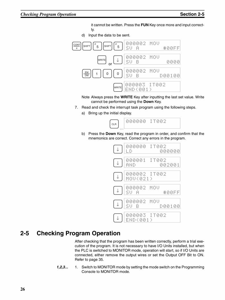
it cannot be written. Press the FUN Key once more and input correct-ly.
d) Input the data to be sent.
or
Note Always press the WRITE Key after inputting the last set value. Writecannot be performed using the Down Key.
7. Read and check the interrupt task program using the following steps.
a) Bring up the initial display.
…b) Press the Down Key, read the program in order, and confirm that the
mnemonics are correct. Correct any errors in the program.
2-5 Checking Program OperationAfter checking that the program has been written correctly, perform a trial exe-cution of the program. It is not necessary to have I/O Units installed, but whenthe PLC is switched to MONITOR mode, operation will start, so if I/O Units areconnected, either remove the output wires or set the Output OFF Bit to ON.Refer to page 35.
1,2,3... 1. Switch to MONITOR mode by setting the mode switch on the ProgrammingConsole to MONITOR mode.
CONT
#SHIFT
F5 SHIFT
F5
000002 MOVSV A #00FF
WRITE ↓000002 MOVSV B 0000
EMDM 1 0 0
000002 MOVSV B D00100
WRITE000003 IT002END(001)
CLR000000 IT002
↓000000 IT002LD 000000
↓000001 IT002AND 002001
↓000002 IT002MOV(021)
↓000002 MOVSV A #00FF
↓000002 MOVSV B D00100
↓000003 IT002END(001)
26
Checking Program Operation Section 2-5
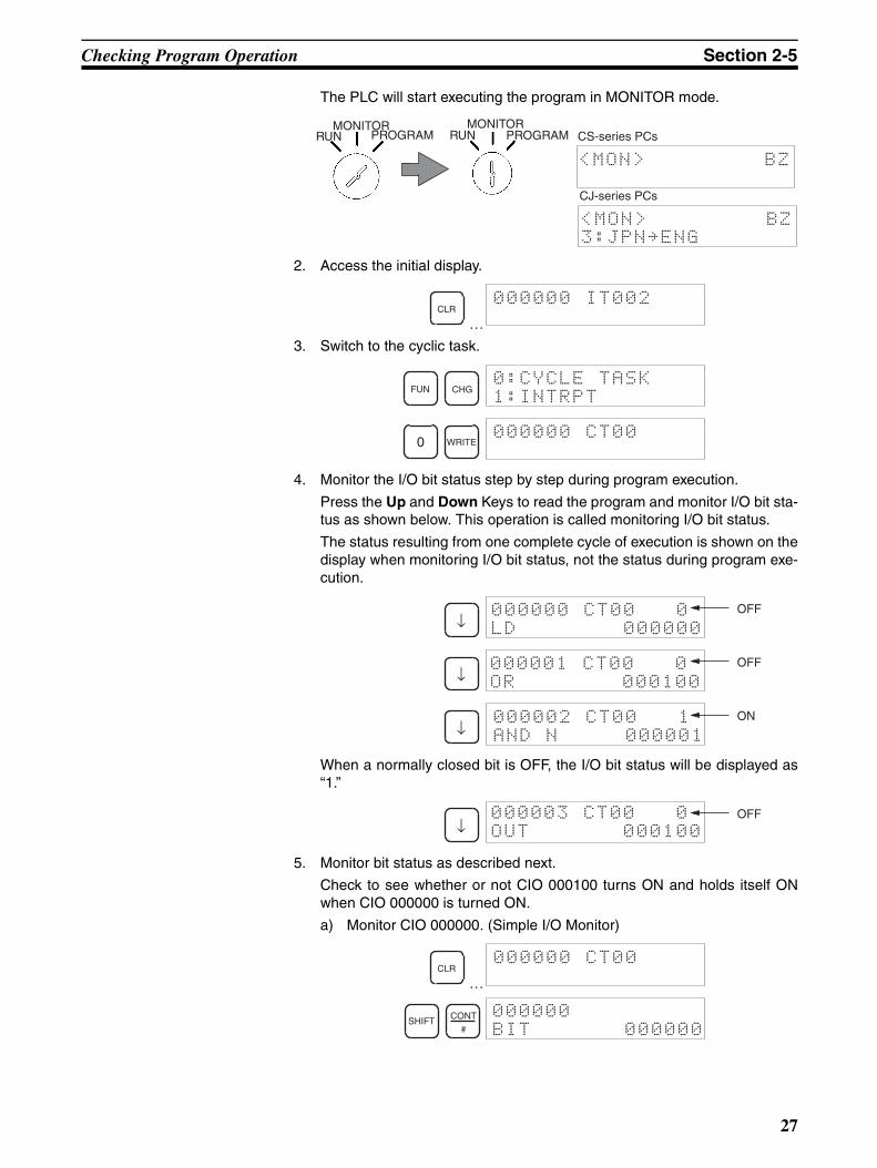
The PLC will start executing the program in MONITOR mode.
2. Access the initial display.
…3. Switch to the cyclic task.
4. Monitor the I/O bit status step by step during program execution.
Press the Up and Down Keys to read the program and monitor I/O bit sta-tus as shown below. This operation is called monitoring I/O bit status.
The status resulting from one complete cycle of execution is shown on thedisplay when monitoring I/O bit status, not the status during program exe-cution.
When a normally closed bit is OFF, the I/O bit status will be displayed as“1.”
5. Monitor bit status as described next.
Check to see whether or not CIO 000100 turns ON and holds itself ONwhen CIO 000000 is turned ON.
a) Monitor CIO 000000. (Simple I/O Monitor)
…
RUNMONITOR
PROGRAM RUNMONITOR
PROGRAM
<MON> BZ
CS-series PCs
<MON> BZ3:JPN~ENG
CJ-series PCs
CLR000000 IT002
FUN CHG0:CYCLE TASK1:INTRPT
0 WRITE000000 CT00
↓000000 CT00 0LD 000000
OFF
↓000001 CT00 0OR 000100
OFF
↓000002 CT00 1AND N 000001
ON
↓000003 CT00 0OUT 000100
OFF
CLR000000 CT00
SHIFT CONT
#
000000BIT 000000
27
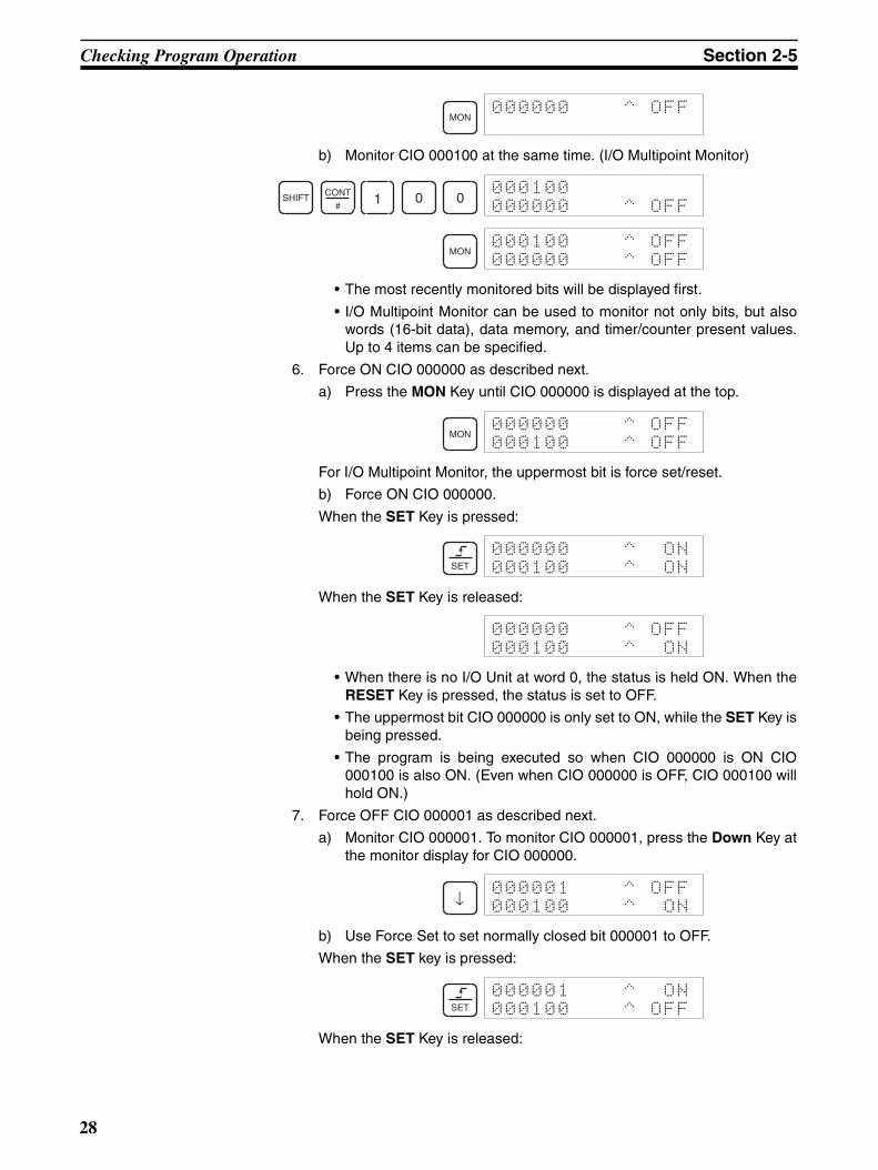
Checking Program Operation Section 2-5
b) Monitor CIO 000100 at the same time. (I/O Multipoint Monitor)
• The most recently monitored bits will be displayed first.
• I/O Multipoint Monitor can be used to monitor not only bits, but alsowords (16-bit data), data memory, and timer/counter present values.Up to 4 items can be specified.
6. Force ON CIO 000000 as described next.
a) Press the MON Key until CIO 000000 is displayed at the top.
For I/O Multipoint Monitor, the uppermost bit is force set/reset.
b) Force ON CIO 000000.
When the SET Key is pressed:
When the SET Key is released:
• When there is no I/O Unit at word 0, the status is held ON. When theRESET Key is pressed, the status is set to OFF.
• The uppermost bit CIO 000000 is only set to ON, while the SET Key isbeing pressed.
• The program is being executed so when CIO 000000 is ON CIO000100 is also ON. (Even when CIO 000000 is OFF, CIO 000100 willhold ON.)
7. Force OFF CIO 000001 as described next.
a) Monitor CIO 000001. To monitor CIO 000001, press the Down Key atthe monitor display for CIO 000000.
b) Use Force Set to set normally closed bit 000001 to OFF.
When the SET key is pressed:
When the SET Key is released:
MON000000 ^ OFF
SHIFT CONT
#1 0 0
000100000000 ^ OFF
MON000100 ^ OFF000000 ^ OFF
MON000000 ^ OFF000100 ^ OFF
SET
000000 ^ ON000100 ^ ON
000000 ^ OFF000100 ^ ON
↓000001 ^ OFF000100 ^ ON
SET
000001 ^ ON000100 ^ OFF
28
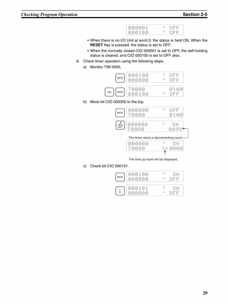
Checking Program Operation Section 2-5
• When there is no I/O Unit at word 0, the status is held ON. When theRESET Key is pressed, the status is set to OFF.
• When the normally closed CIO 000001 is set to OFF, the self-holdingstatus is cleared, and CIO 000100 is set to OFF also.
8. Check timer operation using the following steps.
a) Monitor TIM 0000.
b) Move bit CIO 000000 to the top.
c) Check bit CIO 000101.
000001 ^ OFF000100 ^ OFF
MON000100 ^ OFF000000 ^ OFF
TIM MONT0000 0100000100 ^ OFF
MON000000 ^ OFFT0000 0100
SET000000 ^ ONT0000 0099
The timer starts a decrementing count.
000000 ^ ONT0000 0000
The time up mark will be displayed.
MON000100 ^ ON000000 ^ OFF
↓000101 ^ ON000000 ^ OFF
29

31
SECTION 3Operation
This section describes the basic operations of the Programming Console, including initializing memory and creating I/Otables. It also covers the 3 input modes available on the Programming Console.
3-1 Starting Operation . . . . . . . . . . . . . . . . . . . . . . . . . . . . . . . . . . . . . . . . . . . . . . 32
3-1-1 CS1 CPU Units . . . . . . . . . . . . . . . . . . . . . . . . . . . . . . . . . . . . . . . . . 32
3-1-2 CJ1/CJ1-H/CS1-H CPU Units . . . . . . . . . . . . . . . . . . . . . . . . . . . . . 33
3-2 Changing Operating Modes . . . . . . . . . . . . . . . . . . . . . . . . . . . . . . . . . . . . . . 35
3-3 Key Functions . . . . . . . . . . . . . . . . . . . . . . . . . . . . . . . . . . . . . . . . . . . . . . . . . 36
3-4 Clearing Memory Areas . . . . . . . . . . . . . . . . . . . . . . . . . . . . . . . . . . . . . . . . . 37
3-4-1 All Clear . . . . . . . . . . . . . . . . . . . . . . . . . . . . . . . . . . . . . . . . . . . . . . 39
3-4-2 Memory Clear. . . . . . . . . . . . . . . . . . . . . . . . . . . . . . . . . . . . . . . . . . 41
3-5 Buzzer Operation . . . . . . . . . . . . . . . . . . . . . . . . . . . . . . . . . . . . . . . . . . . . . . 42
3-6 Selecting Tasks . . . . . . . . . . . . . . . . . . . . . . . . . . . . . . . . . . . . . . . . . . . . . . . . 43
3-7 I/O Table Operations . . . . . . . . . . . . . . . . . . . . . . . . . . . . . . . . . . . . . . . . . . . . 46
3-7-1 I/O Table Create . . . . . . . . . . . . . . . . . . . . . . . . . . . . . . . . . . . . . . . . 46
3-7-2 I/O Table Verify . . . . . . . . . . . . . . . . . . . . . . . . . . . . . . . . . . . . . . . . 48
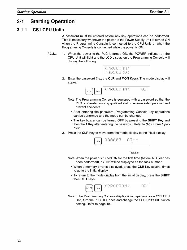
Starting Operation Section 3-1
3-1 Starting Operation
3-1-1 CS1 CPU UnitsA password must be entered before any key operations can be performed.This is necessary whenever the power to the Power Supply Unit is turned ONwhen the Programming Console is connected to the CPU Unit, or when theProgramming Console is connected while the power is ON.
1,2,3... 1. When the power to the PLC is turned ON, the POWER indicator on theCPU Unit will light and the LCD display on the Programming Console willdisplay the following.
2. Enter the password (i.e., the CLR and MON Keys). The mode display willappear.
Note The Programming Console is equipped with a password so that thePLC is operated only by qualified staff to ensure safe operation andprevent accidents.
• After entering the password, Programming Console key operationscan be performed and the mode can be changed.
• The key buzzer can be turned OFF by pressing the SHIFT Key andthen the 1 Key after entering the password. Refer to 3-5 Buzzer Oper-ation.
3. Press the CLR Key to move from the mode display to the initial display.
Note When the power is turned ON for the first time (before All Clear hasbeen performed), “CT**” will be displayed as the task number.
• When a memory error is displayed, press the CLR Key several timesto go to the initial display.
• To return to the mode display from the initial display, press the SHIFTthen CLR Keys.
Note If the Programming Console display is in Japanese for a CS1 CPUUnit, turn the PLC OFF once and change the CPU Unit’s DIP switchsetting. Refer to page 18.
<PROGRAM>PASSWORD!
CLR MON<PROGRAM> BZ
CLR 000000 CT**
Task No.
SHIFT CLR<PROGRAM> BZ
32
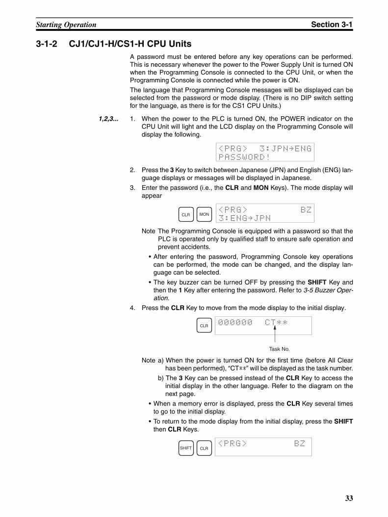
Starting Operation Section 3-1
3-1-2 CJ1/CJ1-H/CS1-H CPU UnitsA password must be entered before any key operations can be performed.This is necessary whenever the power to the Power Supply Unit is turned ONwhen the Programming Console is connected to the CPU Unit, or when theProgramming Console is connected while the power is ON.
The language that Programming Console messages will be displayed can beselected from the password or mode display. (There is no DIP switch settingfor the language, as there is for the CS1 CPU Units.)
1,2,3... 1. When the power to the PLC is turned ON, the POWER indicator on theCPU Unit will light and the LCD display on the Programming Console willdisplay the following.
2. Press the 3 Key to switch between Japanese (JPN) and English (ENG) lan-guage displays or messages will be displayed in Japanese.
3. Enter the password (i.e., the CLR and MON Keys). The mode display willappear
Note The Programming Console is equipped with a password so that thePLC is operated only by qualified staff to ensure safe operation andprevent accidents.
• After entering the password, Programming Console key operationscan be performed, the mode can be changed, and the display lan-guage can be selected.
• The key buzzer can be turned OFF by pressing the SHIFT Key andthen the 1 Key after entering the password. Refer to 3-5 Buzzer Oper-ation.
4. Press the CLR Key to move from the mode display to the initial display.
Note a) When the power is turned ON for the first time (before All Clearhas been performed), “CT**” will be displayed as the task number.
b) The 3 Key can be pressed instead of the CLR Key to access theinitial display in the other language. Refer to the diagram on thenext page.
• When a memory error is displayed, press the CLR Key several timesto go to the initial display.
• To return to the mode display from the initial display, press the SHIFTthen CLR Keys.
<PRG> 3:JPN~ENG
PASSWORD!
CLR MON<PRG> BZ
3:ENG~JPN
CLR 000000 CT**
Task No.
SHIFT CLR<PRG> BZ
33
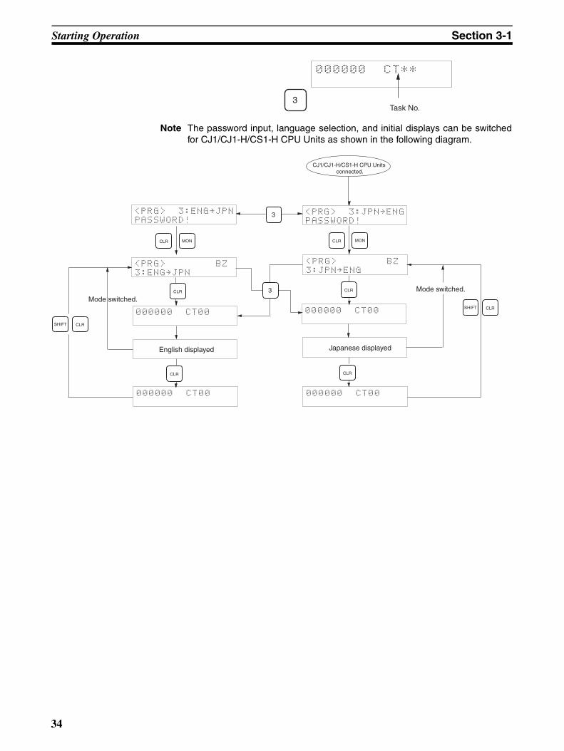
Starting Operation Section 3-1
Note The password input, language selection, and initial displays can be switchedfor CJ1/CJ1-H/CS1-H CPU Units as shown in the following diagram.
3
000000 CT**
Task No.
<PRG> 3:ENG~JPN
PASSWORD!3
3CLR
<PRG> BZ
3:ENG~JPN
CJ1/CJ1-H/CS1-H CPU Units connected.
<PRG> 3:JPN~ENG
PASSWORD!
CLR MON
CLR
<PRG> BZ
3:JPN~ENG
000000 CT00 000000 CT00
000000 CT00000000 CT00
English displayed Japanese displayed
Mode switched.
SHIFT CLR
SHIFT CLR
Mode switched.
CLR
CLR MON
CLR
34
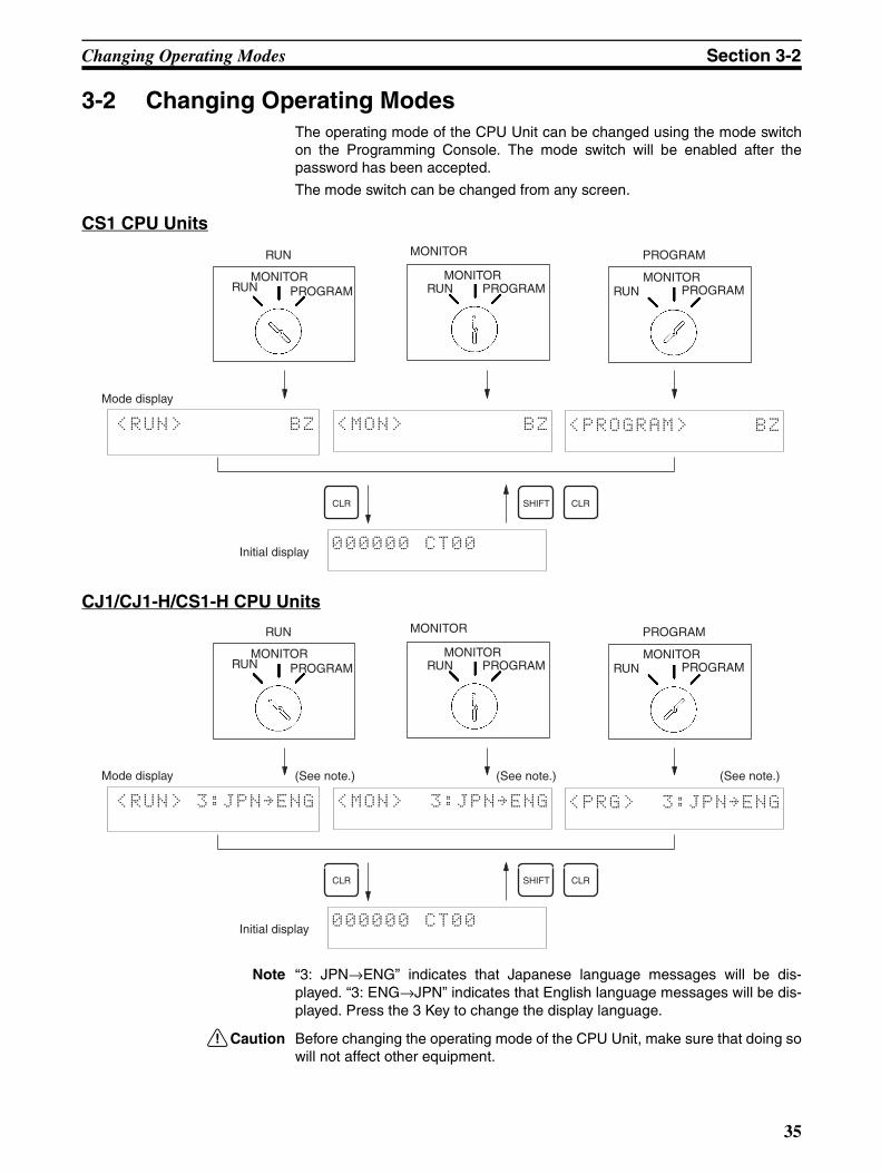
Changing Operating Modes Section 3-2
3-2 Changing Operating ModesThe operating mode of the CPU Unit can be changed using the mode switchon the Programming Console. The mode switch will be enabled after thepassword has been accepted.
The mode switch can be changed from any screen.
CS1 CPU Units
CJ1/CJ1-H/CS1-H CPU Units
Note “3: JPN→ENG” indicates that Japanese language messages will be dis-played. “3: ENG→JPN” indicates that English language messages will be dis-played. Press the 3 Key to change the display language.
!Caution Before changing the operating mode of the CPU Unit, make sure that doing sowill not affect other equipment.
PROGRAMMONITORRUN
<RUN> BZ <MON> BZ <PROGRAM> BZ
000000 CT00Initial display
CLR
Mode display
RUNMONITOR
PROGRAMRUNMONITOR
PROGRAM RUNMONITOR
PROGRAM
CLRSHIFT
PROGRAMMONITORRUN
<RUN> 3:JPN~ENG <MON> 3:JPN~ENG <PRG> 3:JPN~ENG
000000 CT00Initial display
CLR
Mode display
RUNMONITOR
PROGRAMRUNMONITOR
PROGRAM RUNMONITOR
PROGRAM
CLRSHIFT
(See note.) (See note.) (See note.)
35
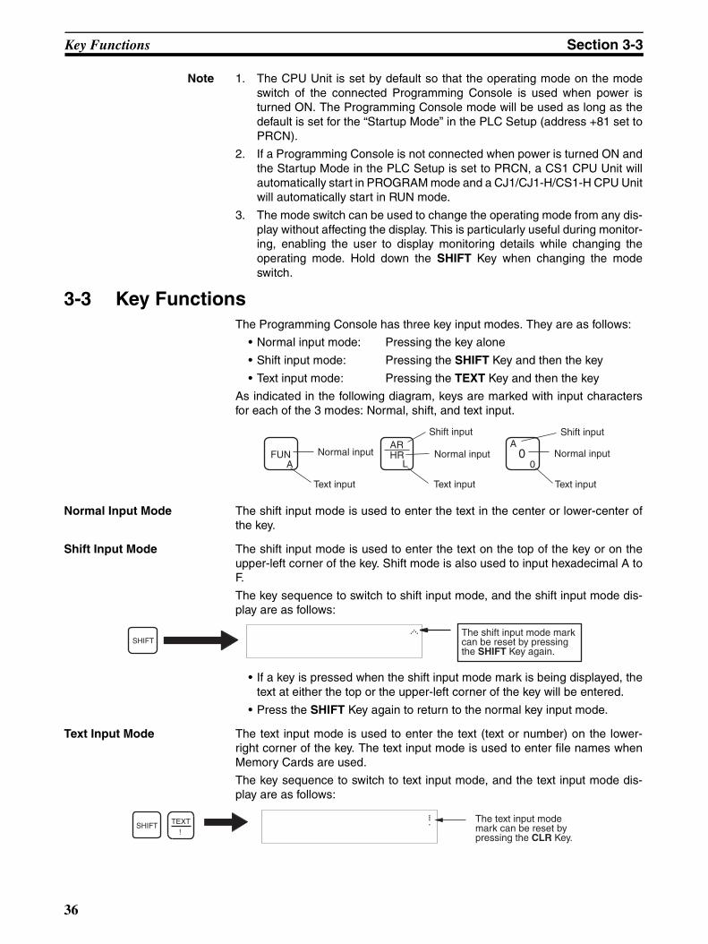
Key Functions Section 3-3
Note 1. The CPU Unit is set by default so that the operating mode on the modeswitch of the connected Programming Console is used when power isturned ON. The Programming Console mode will be used as long as thedefault is set for the “Startup Mode” in the PLC Setup (address +81 set toPRCN).
2. If a Programming Console is not connected when power is turned ON andthe Startup Mode in the PLC Setup is set to PRCN, a CS1 CPU Unit willautomatically start in PROGRAM mode and a CJ1/CJ1-H/CS1-H CPU Unitwill automatically start in RUN mode.
3. The mode switch can be used to change the operating mode from any dis-play without affecting the display. This is particularly useful during monitor-ing, enabling the user to display monitoring details while changing theoperating mode. Hold down the SHIFT Key when changing the modeswitch.
3-3 Key FunctionsThe Programming Console has three key input modes. They are as follows:
• Normal input mode: Pressing the key alone
• Shift input mode: Pressing the SHIFT Key and then the key
• Text input mode: Pressing the TEXT Key and then the key
As indicated in the following diagram, keys are marked with input charactersfor each of the 3 modes: Normal, shift, and text input.
Normal Input Mode The shift input mode is used to enter the text in the center or lower-center ofthe key.
Shift Input Mode The shift input mode is used to enter the text on the top of the key or on theupper-left corner of the key. Shift mode is also used to input hexadecimal A toF.
The key sequence to switch to shift input mode, and the shift input mode dis-play are as follows:
• If a key is pressed when the shift input mode mark is being displayed, thetext at either the top or the upper-left corner of the key will be entered.
• Press the SHIFT Key again to return to the normal key input mode.
Text Input Mode The text input mode is used to enter the text (text or number) on the lower-right corner of the key. The text input mode is used to enter file names whenMemory Cards are used.
The key sequence to switch to text input mode, and the text input mode dis-play are as follows:
Normal input
Text input
Shift input
FUNA
HRL
AR0
A
0
Shift input
Normal input Normal input
Text input Text input
The shift input mode mark can be reset by pressing the SHIFT Key again.
^SHIFT
TEXT!
! The text input mode mark can be reset by pressing the CLR Key.
SHIFT
36
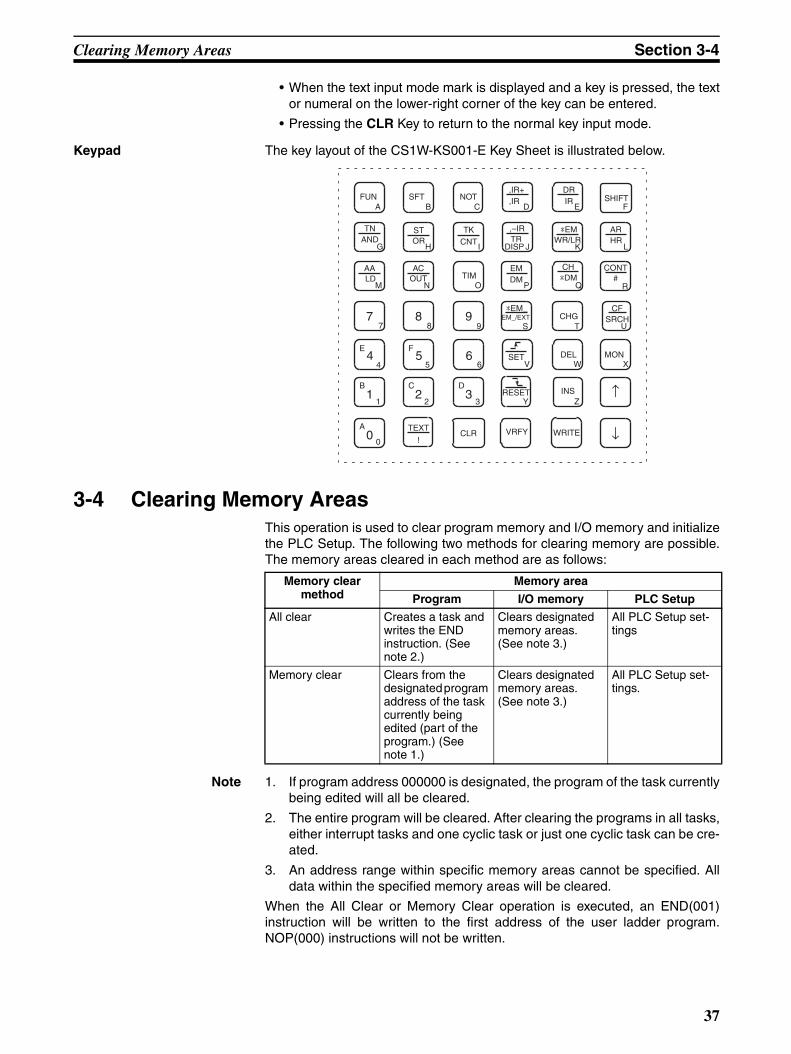
Clearing Memory Areas Section 3-4
• When the text input mode mark is displayed and a key is pressed, the textor numeral on the lower-right corner of the key can be entered.
• Pressing the CLR Key to return to the normal key input mode.
Keypad The key layout of the CS1W-KS001-E Key Sheet is illustrated below.
3-4 Clearing Memory AreasThis operation is used to clear program memory and I/O memory and initializethe PLC Setup. The following two methods for clearing memory are possible.The memory areas cleared in each method are as follows:
Note 1. If program address 000000 is designated, the program of the task currentlybeing edited will all be cleared.
2. The entire program will be cleared. After clearing the programs in all tasks,either interrupt tasks and one cyclic task or just one cyclic task can be cre-ated.
3. An address range within specific memory areas cannot be specified. Alldata within the specified memory areas will be cleared.
When the All Clear or Memory Clear operation is executed, an END(001)instruction will be written to the first address of the user ladder program.NOP(000) instructions will not be written.
ARHR
L
INSZ
CLR
SHIFTF
NOTC
B1
1
C2
2
D3
3
A0
0↓
↑
F5
56
6
WRITE
TIMO
E4
4
77
88
TKCNT
I
99
SFTB
,IR+,IR
D
STOR
H
TNAND
G
ACOUT
N
*EM_EM_/EXT
S
VRFYTEXT
!
FUNA
VSET
RESETY
MONDEL
CHG
CH*DM
*EMWR/LR
EMDM
CFSRCH
U
,–IRTR
DRIR
CONT#
AALD
E
J K
M P Q R
T
W X
DISP
Memory clear method
Memory area
Program I/O memory PLC Setup
All clear Creates a task and writes the END instruction. (See note 2.)
Clears designated memory areas. (See note 3.)
All PLC Setup set-tings
Memory clear Clears from the designated program address of the task currently being edited (part of the program.) (See note 1.)
Clears designated memory areas. (See note 3.)
All PLC Setup set-tings.
37

Clearing Memory Areas Section 3-4
Specifying Memory Areas Not to be Cleared
Letters will be displayed at the bottom of the display for the memory areas thatwill be cleared. If an area is specified to not be cleared, the corresponding let-ter will disappear.
Note The CIO Area is used for I/O word data: I/O bits, Data Link bits, CS/CJ CPUBus Unit bits, Inner Board bits, SYSMAC BUS bits, I/O Terminal bits, Special I/O Unit bits, CompoBus/D (DeviceNet) bits, and work bits. (Inner Board bits,SYSMAC BUS bits, and I/O Terminal bits are supported by CS-series PLCsonly.)
To clear the memory areas that are specified not to be cleared, repeat thesame key sequence. The appropriate letter will be displayed at the bottom ofthe display.
The EM Area cannot be cleared if it has been converted to file memory. Referto Section 7 Memory Card Operations for information on formatting file mem-ory and restoring the normal EM Area.
Letter Areas to be cleared Key sequence
C CIO (See note)
H HR (Holding bits)
W WR (Work bits)
A AR (Auxiliary bits)
T T (Completion Flags/PVs)
C C (Completion Flags/PVs)
D DM (Data memory)
E EM (Extended data mem-ory)
P PLC Setup
000000 CLR MEM?
CHWA TCDE P
Letters at the bottom of the display indicate the memory areas that will be cleared.
CH
*DMSHIFT
AR
HR
*EMWR/LR
ARHRSHIFT
TIM
TK
CNT
EMDM
EMDM
Bank number
SHIFT
SHIFTCF
SRCH
38
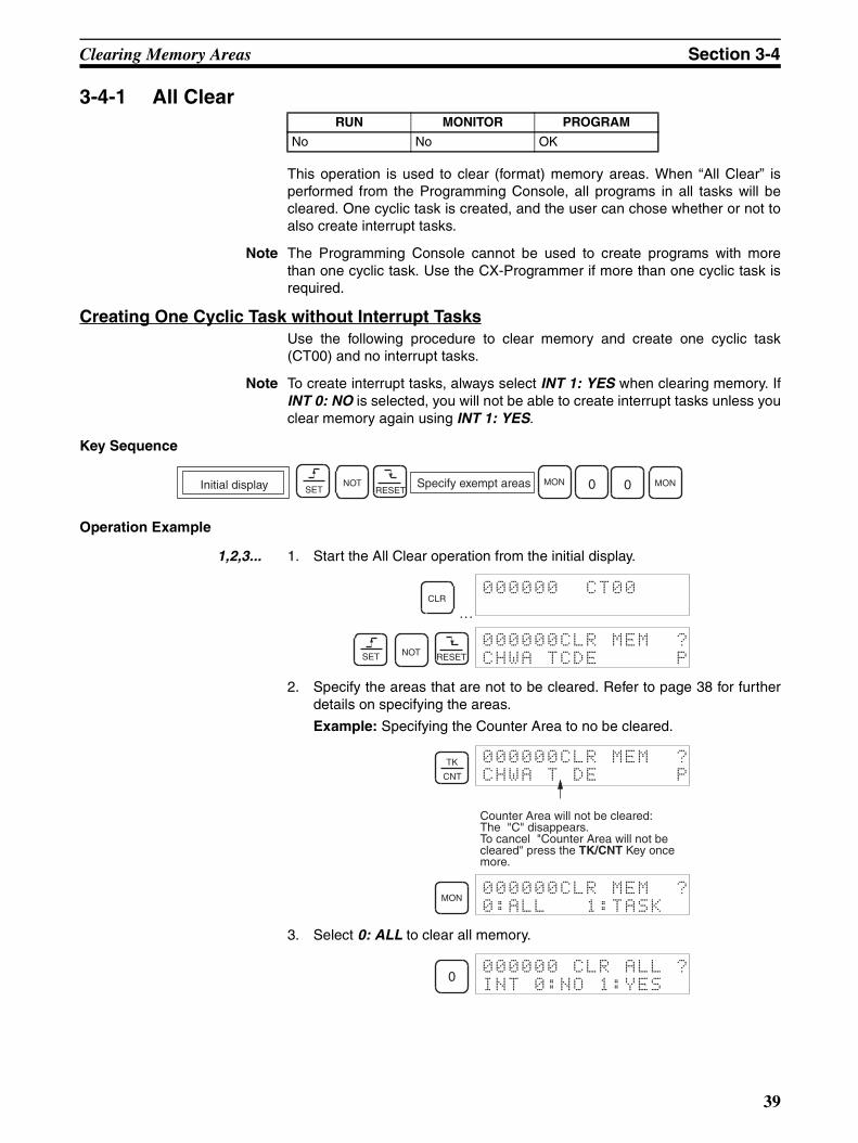
Clearing Memory Areas Section 3-4
3-4-1 All Clear
This operation is used to clear (format) memory areas. When “All Clear” isperformed from the Programming Console, all programs in all tasks will becleared. One cyclic task is created, and the user can chose whether or not toalso create interrupt tasks.
Note The Programming Console cannot be used to create programs with morethan one cyclic task. Use the CX-Programmer if more than one cyclic task isrequired.
Creating One Cyclic Task without Interrupt TasksUse the following procedure to clear memory and create one cyclic task(CT00) and no interrupt tasks.
Note To create interrupt tasks, always select INT 1: YES when clearing memory. IfINT 0: NO is selected, you will not be able to create interrupt tasks unless youclear memory again using INT 1: YES.
Key Sequence
Operation Example
1,2,3... 1. Start the All Clear operation from the initial display.
…
2. Specify the areas that are not to be cleared. Refer to page 38 for furtherdetails on specifying the areas.
Example: Specifying the Counter Area to no be cleared.
3. Select 0: ALL to clear all memory.
RUN MONITOR PROGRAM
No No OK
Specify exempt areas MON0NOTInitial display MON 0SET RESET
CLR000000 CT00
SET NOT RESET
000000CLR MEM ?
CHWA TCDE P
TK
CNT
000000CLR MEM ?
CHWA T DE P
Counter Area will not be cleared: The "C" disappears.To cancel "Counter Area will not be cleared" press the TK/CNT Key once more.
MON000000CLR MEM ?
0:ALL 1:TASK
0000000 CLR ALL ?
INT 0:NO 1:YES
39
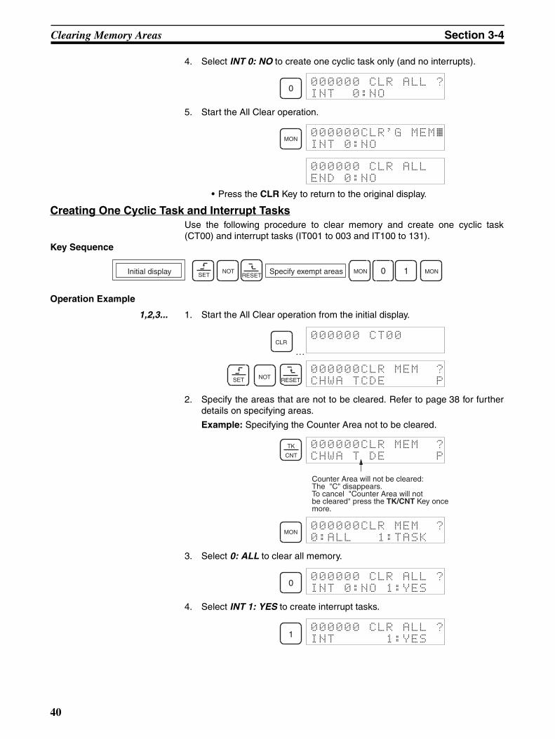
Clearing Memory Areas Section 3-4
4. Select INT 0: NO to create one cyclic task only (and no interrupts).
5. Start the All Clear operation.
• Press the CLR Key to return to the original display.
Creating One Cyclic Task and Interrupt TasksUse the following procedure to clear memory and create one cyclic task(CT00) and interrupt tasks (IT001 to 003 and IT100 to 131).
Key Sequence
Operation Example
1,2,3... 1. Start the All Clear operation from the initial display.
…
2. Specify the areas that are not to be cleared. Refer to page 38 for furtherdetails on specifying areas.
Example: Specifying the Counter Area not to be cleared.
3. Select 0: ALL to clear all memory.
4. Select INT 1: YES to create interrupt tasks.
0000000 CLR ALL ?
INT 0:NO
MON000000CLR'G MEM~INT 0:NO
000000 CLR ALL
END 0:NO
Specify exempt areas MONNOT 1Initial display MON 0SET RESET
CLR000000 CT00
SET NOT RESET
000000CLR MEM ?
CHWA TCDE P
TK
CNT
000000CLR MEM ?
CHWA T DE P
Counter Area will not be cleared: The "C" disappears.To cancel "Counter Area will notbe cleared" press the TK/CNT Key once more.
MON000000CLR MEM ?
0:ALL 1:TASK
0000000 CLR ALL ?
INT 0:NO 1:YES
1000000 CLR ALL ?
INT 1:YES
40

Clearing Memory Areas Section 3-4
5. Start the All Clear operation.
• Press the CLR Key to return to the original display.
Note When the All Clear operation is performed from the ProgrammingConsole, cyclic task No. 0 will be automatically activated at PLC star-tup.
3-4-2 Memory Clear
This operation is used to clear the program in the current task starting with aspecified program address within the current task. It is also used to clear I/Omemory and the PLC Setup.
Key Sequence
Operation Example
1,2,3... 1. Start the Memory Clear operation.
…
2. Specify the areas that are not to be cleared. Refer to page 38 for furtherdetails on specifying areas.
Example: Specifying the Counter Area to not be cleared.
3. Specify the first address to be cleared in the program.
Example: Clear the program starting from program address 000123 (in-cluding 000123).
MON000000CLR'G MEM~INT 1:YES
000000 CLR ALL
END 1:YES
RUN MONITOR PROGRAM
No No OK
Specify exempt areasMONNOT
Specify starting address for clear operationInitial display 1 MONSET RESET
CLR000000 CT00
Current Task No.
SET NOT RESET
000000CLR MEM ?
CHWA TCDE P
TK
CNT
000000CLR MEM ?
CHWA T DE P
Counter Area will not be cleared: The "C" disappears.To cancel "Counter Area will not be cleared" press the TK/CNT Key once more.
1 2 3000123CLR MEM ?
CHWA T DE P
MON000123CLR MEM ?
0:ALL 1:TASK
41
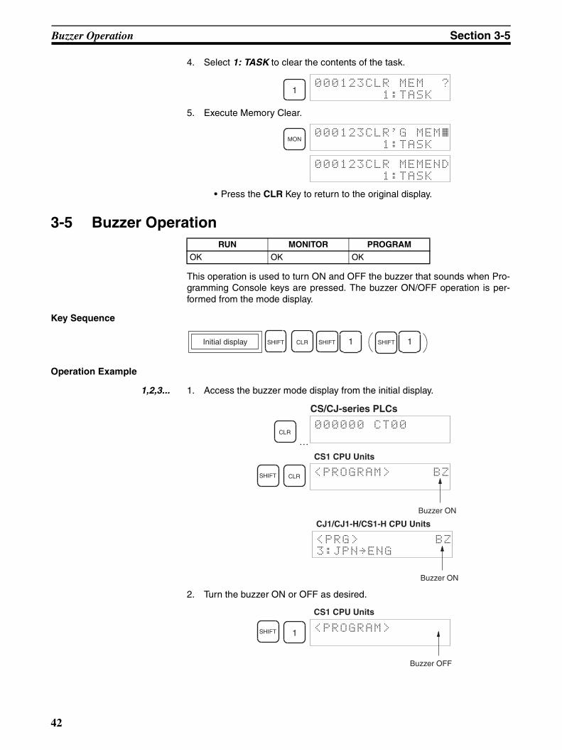
Buzzer Operation Section 3-5
4. Select 1: TASK to clear the contents of the task.
5. Execute Memory Clear.
• Press the CLR Key to return to the original display.
3-5 Buzzer Operation
This operation is used to turn ON and OFF the buzzer that sounds when Pro-gramming Console keys are pressed. The buzzer ON/OFF operation is per-formed from the mode display.
Key Sequence
Operation Example
1,2,3... 1. Access the buzzer mode display from the initial display.
…
2. Turn the buzzer ON or OFF as desired.
1000123CLR MEM ?
1:TASK
MON000123CLR'G MEM~ 1:TASK
000123CLR MEMEND
1:TASK
RUN MONITOR PROGRAM
OK OK OK
SHIFT CLR SHIFT 1 1SHIFTInitial display
CLR000000 CT00
CS/CJ-series PLCs
SHIFT CLR <PROGRAM> BZ
Buzzer ON
CS1 CPU Units
<PRG> BZ
3:JPN~ENG
Buzzer ON
CJ1/CJ1-H/CS1-H CPU Units
SHIFT 1 <PROGRAM>
Buzzer OFF
CS1 CPU Units
42

Selecting Tasks Section 3-6
Note a) When an error occurs, the buzzer will sound regardless of whetherthe buzzer has been turned ON or OFF.
b) The mode display is displayed immediately after the password hasbeen entered or after the mode is changed.
c) For CJ1/CJ1-H/CS1-H CPU Units, the display language can beswitched by pressing the 3 Key while “3: JPN→ENG” or “3:ENG→JPN” is being displayed.
3-6 Selecting Tasks
This operation allows the user to select the task and the type of task (cyclic orinterrupt.) From the Programming Console however, only interrupt task num-bers 1,2, and 3 (IT100 to 131) can be newly created. Interrupt task numbers 0and 4 to 99 (IT132 to 255) cannot be created.
Outline of Key Sequence for Selecting Tasks
<PRG>
3:JPN~ENG
Buzzer ON
CJ1/CJ1-H/CS1-H CPU Units
RUN MONITOR PROGRAM
OK OK OK
0: CYCLE TASK
1: INTRPT
1
CYCLE TASK No.?
00
INTRPT #?
000
000000 CT00 000000 IT000
000000 IT255
to
FUN
FUN
Task No.
FlashingFlashing
0 CLR CLR
WRITETask No.
CHG
CHG
WRITE
43
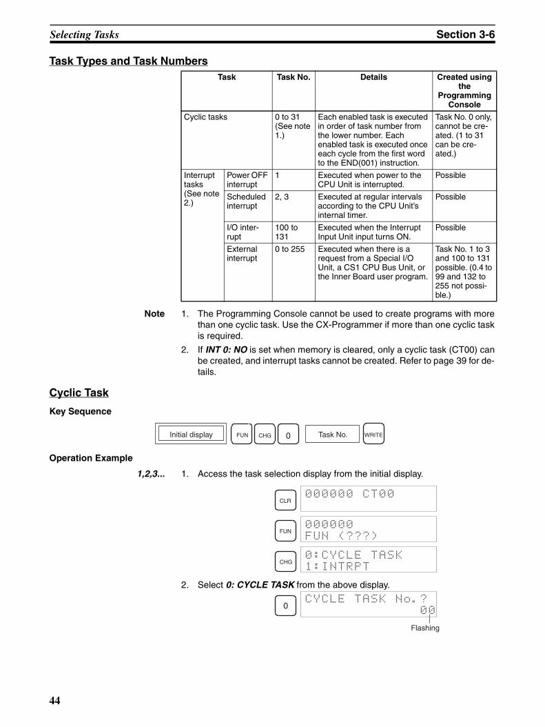
Selecting Tasks Section 3-6
Task Types and Task Numbers
Note 1. The Programming Console cannot be used to create programs with morethan one cyclic task. Use the CX-Programmer if more than one cyclic taskis required.
2. If INT 0: NO is set when memory is cleared, only a cyclic task (CT00) canbe created, and interrupt tasks cannot be created. Refer to page 39 for de-tails.
Cyclic Task
Key Sequence
Operation Example
1,2,3... 1. Access the task selection display from the initial display.
2. Select 0: CYCLE TASK from the above display.
Task Task No. Details Created using the
Programming Console
Cyclic tasks 0 to 31(See note 1.)
Each enabled task is executed in order of task number from the lower number. Each enabled task is executed once each cycle from the first word to the END(001) instruction.
Task No. 0 only, cannot be cre-ated. (1 to 31 can be cre-ated.)
Interrupt tasks (See note 2.)
Power OFF interrupt
1 Executed when power to the CPU Unit is interrupted.
Possible
Scheduled interrupt
2, 3 Executed at regular intervals according to the CPU Unit’s internal timer.
Possible
I/O inter-rupt
100 to 131
Executed when the Interrupt Input Unit input turns ON.
Possible
External interrupt
0 to 255 Executed when there is a request from a Special I/O Unit, a CS1 CPU Bus Unit, or the Inner Board user program.
Task No. 1 to 3 and 100 to 131 possible. (0.4 to 99 and 132 to 255 not possi-ble.)
Initial display FUN CHG 0 WRITETask No.
CLR000000 CT00
FUN000000
FUN (???)
CHG0:CYCLE TASK
1:INTRPT
0CYCLE TASK No.?
00
Flashing
44
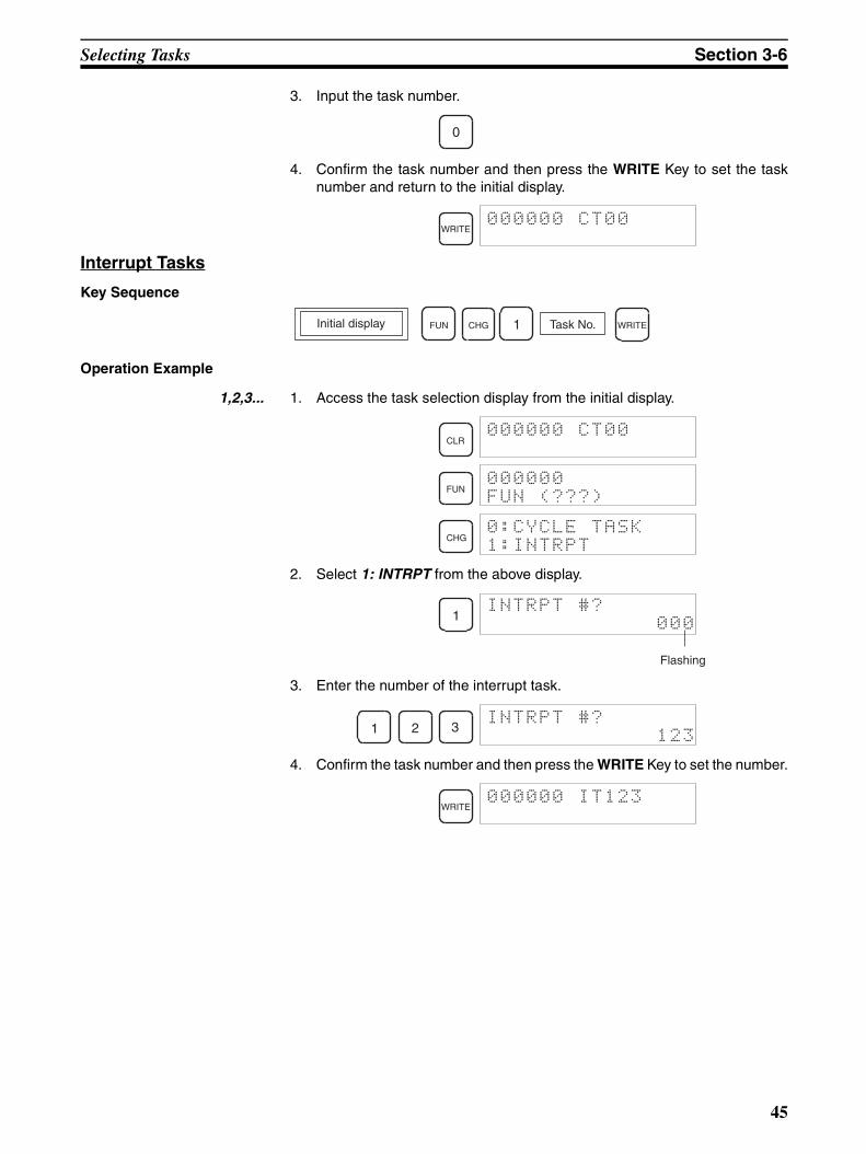
Selecting Tasks Section 3-6
3. Input the task number.
4. Confirm the task number and then press the WRITE Key to set the tasknumber and return to the initial display.
Interrupt Tasks
Key Sequence
Operation Example
1,2,3... 1. Access the task selection display from the initial display.
2. Select 1: INTRPT from the above display.
3. Enter the number of the interrupt task.
4. Confirm the task number and then press the WRITE Key to set the number.
0
WRITE000000 CT00
Task No.1FUN WRITEInitial display CHG
CLR000000 CT00
FUN000000
FUN (???)
CHG0:CYCLE TASK
1:INTRPT
1INTRPT #?
000
Flashing
1 2 3INTRPT #?
123
WRITE000000 IT123
45
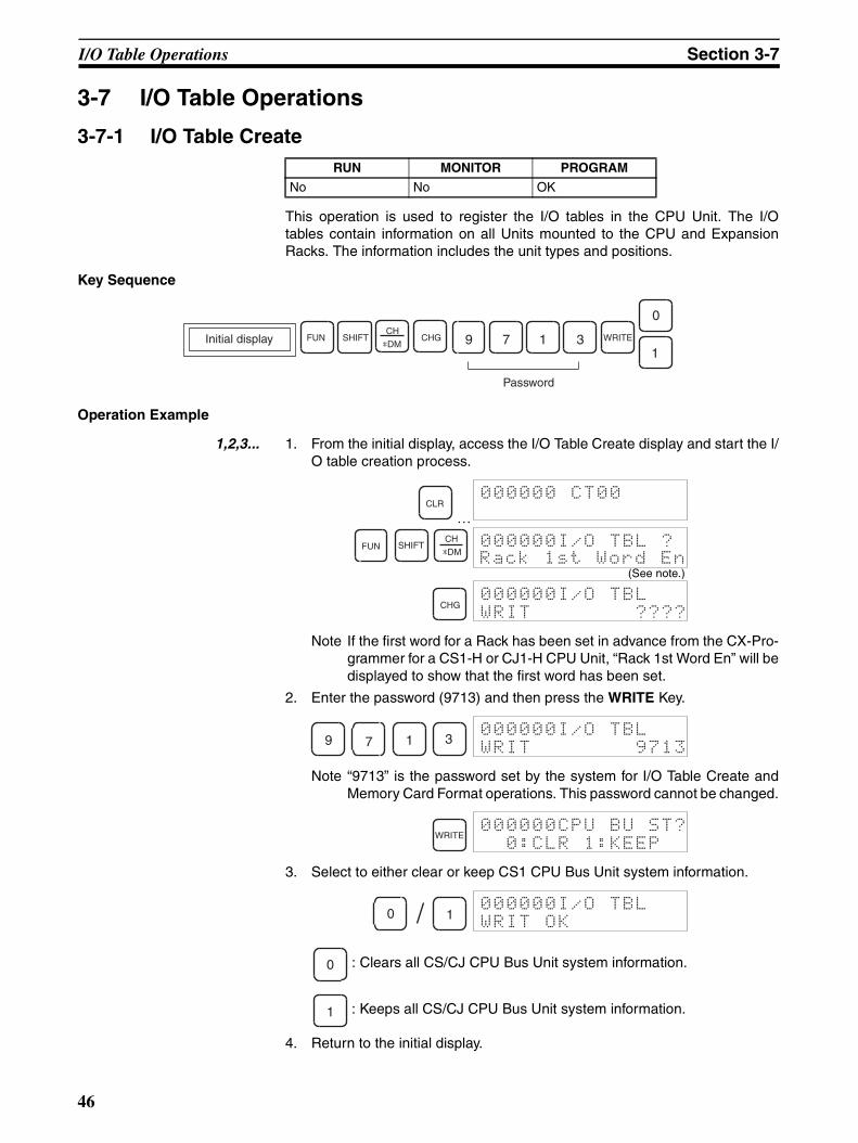
I/O Table Operations Section 3-7
3-7 I/O Table Operations
3-7-1 I/O Table Create
This operation is used to register the I/O tables in the CPU Unit. The I/Otables contain information on all Units mounted to the CPU and ExpansionRacks. The information includes the unit types and positions.
Key Sequence
Operation Example
1,2,3... 1. From the initial display, access the I/O Table Create display and start the I/O table creation process.
…
Note If the first word for a Rack has been set in advance from the CX-Pro-grammer for a CS1-H or CJ1-H CPU Unit, “Rack 1st Word En” will bedisplayed to show that the first word has been set.
2. Enter the password (9713) and then press the WRITE Key.
Note “9713” is the password set by the system for I/O Table Create andMemory Card Format operations. This password cannot be changed.
3. Select to either clear or keep CS1 CPU Bus Unit system information.
: Clears all CS/CJ CPU Bus Unit system information.
: Keeps all CS/CJ CPU Bus Unit system information.
4. Return to the initial display.
RUN MONITOR PROGRAM
No No OK
1FUN WRITE
0
3179SHIFTCH
*DM
Password
Initial display CHG
CLR000000 CT00
FUN SHIFTCH
*DM000000I/O TBL ?
Rack 1st Word En(See note.)
CHG000000I/O TBL
WRIT ????
9 7 1 3000000I/O TBL
WRIT 9713
WRITE000000CPU BU ST?
0:CLR 1:KEEP
0 1000000I/O TBL
WRIT OK
0
1
46
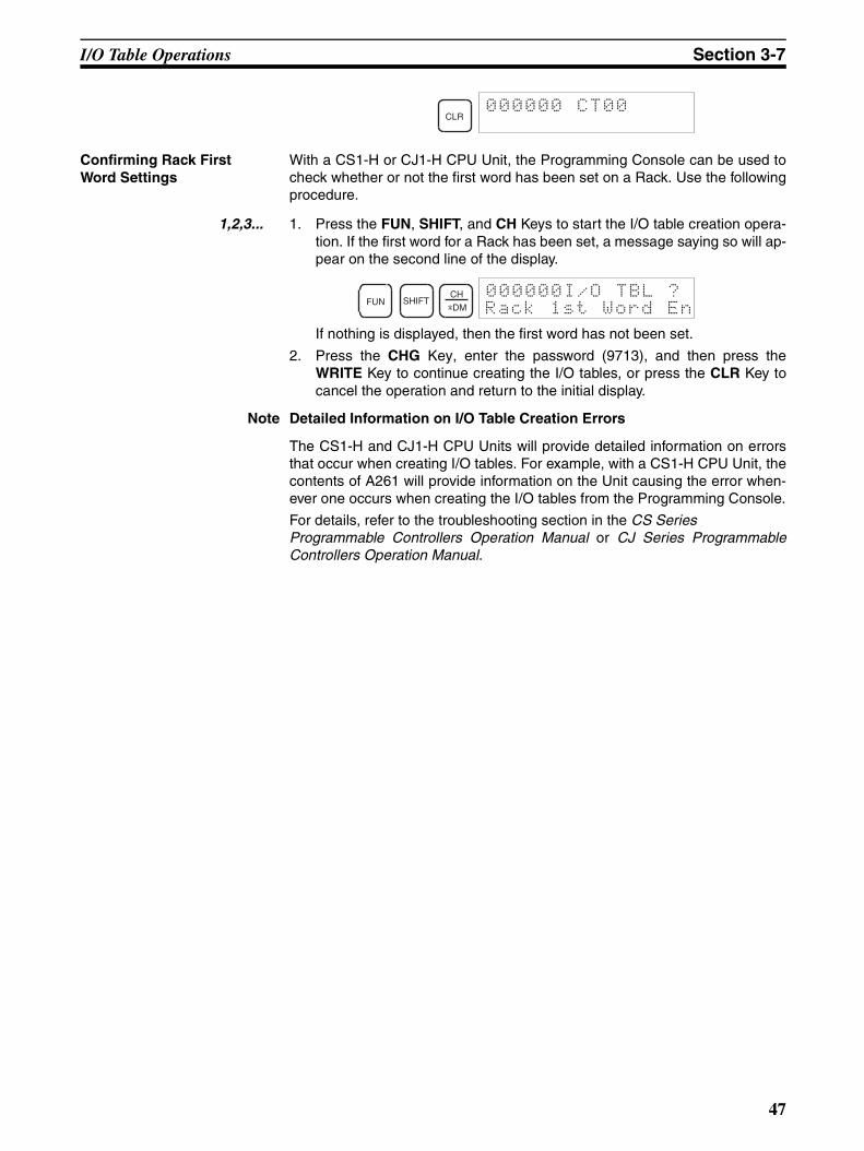
I/O Table Operations Section 3-7
Confirming Rack First Word Settings
With a CS1-H or CJ1-H CPU Unit, the Programming Console can be used tocheck whether or not the first word has been set on a Rack. Use the followingprocedure.
1,2,3... 1. Press the FUN, SHIFT, and CH Keys to start the I/O table creation opera-tion. If the first word for a Rack has been set, a message saying so will ap-pear on the second line of the display.
If nothing is displayed, then the first word has not been set.
2. Press the CHG Key, enter the password (9713), and then press theWRITE Key to continue creating the I/O tables, or press the CLR Key tocancel the operation and return to the initial display.
Note Detailed Information on I/O Table Creation Errors
The CS1-H and CJ1-H CPU Units will provide detailed information on errorsthat occur when creating I/O tables. For example, with a CS1-H CPU Unit, thecontents of A261 will provide information on the Unit causing the error when-ever one occurs when creating the I/O tables from the Programming Console.
For details, refer to the troubleshooting section in the CS Series Programmable Controllers Operation Manual or CJ Series ProgrammableControllers Operation Manual.
CLR000000 CT00
FUN SHIFTCH
*DM
000000I/O TBL ?
Rack 1st Word En
47
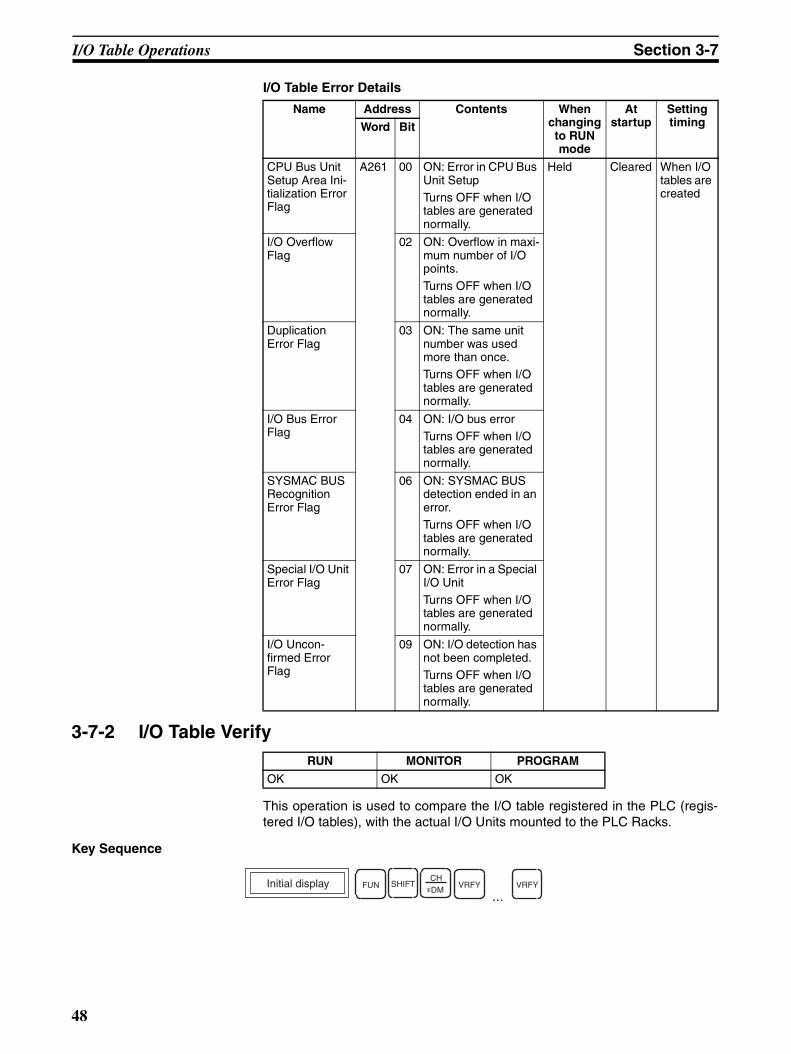
I/O Table Operations Section 3-7
I/O Table Error Details
3-7-2 I/O Table Verify
This operation is used to compare the I/O table registered in the PLC (regis-tered I/O tables), with the actual I/O Units mounted to the PLC Racks.
Key Sequence
Name Address Contents When changing to RUN mode
At startup
Setting timingWord Bit
CPU Bus Unit Setup Area Ini-tialization Error Flag
A261 00 ON: Error in CPU Bus Unit SetupTurns OFF when I/O tables are generated normally.
Held Cleared When I/O tables are created
I/O Overflow Flag
02 ON: Overflow in maxi-mum number of I/O points.Turns OFF when I/O tables are generated normally.
Duplication Error Flag
03 ON: The same unit number was used more than once.Turns OFF when I/O tables are generated normally.
I/O Bus Error Flag
04 ON: I/O bus errorTurns OFF when I/O tables are generated normally.
SYSMAC BUS Recognition Error Flag
06 ON: SYSMAC BUS detection ended in an error.Turns OFF when I/O tables are generated normally.
Special I/O Unit Error Flag
07 ON: Error in a Special I/O UnitTurns OFF when I/O tables are generated normally.
I/O Uncon-firmed Error Flag
09 ON: I/O detection has not been completed.Turns OFF when I/O tables are generated normally.
RUN MONITOR PROGRAM
OK OK OK
Initial display FUN SHIFTCH*DM
VRFY VRFY
...
48
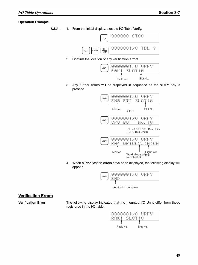
I/O Table Operations Section 3-7
Operation Example
1,2,3... 1. From the initial display, execute I/O Table Verify.
2. Confirm the location of any verification errors.
3. Any further errors will be displayed in sequence as the VRFY Key ispressed.
4. When all verification errors have been displayed, the following display willappear.
Verification Errors
Verification Error The following display indicates that the mounted I/O Units differ from thoseregistered in the I/O table.
CLR000000 CT00
FUN SHIFTCH
*DM
000000I/O TBL ?
VRFY 000000I/O VRFY
RAK1 SLOT10
Rack No. Slot No.
VRFY000000I/O VRFY
RM0 RT2 SLOT10
Master Slot No.Slave
VRFY000000I/O VRFY
CPU BU No.10
No. of CS1 CPU Bus Units (CPU Bus Units)
VRFY 000000I/O VRFY
RM4 OPTCL23(H)CH
Master High/Low bitsWord allocated
to Optical I/O
VRFY000000I/O VRFY
END
Verification complete
000000I/O VRFY
RAK1 SLOT10
Rack No. Slot No.
49
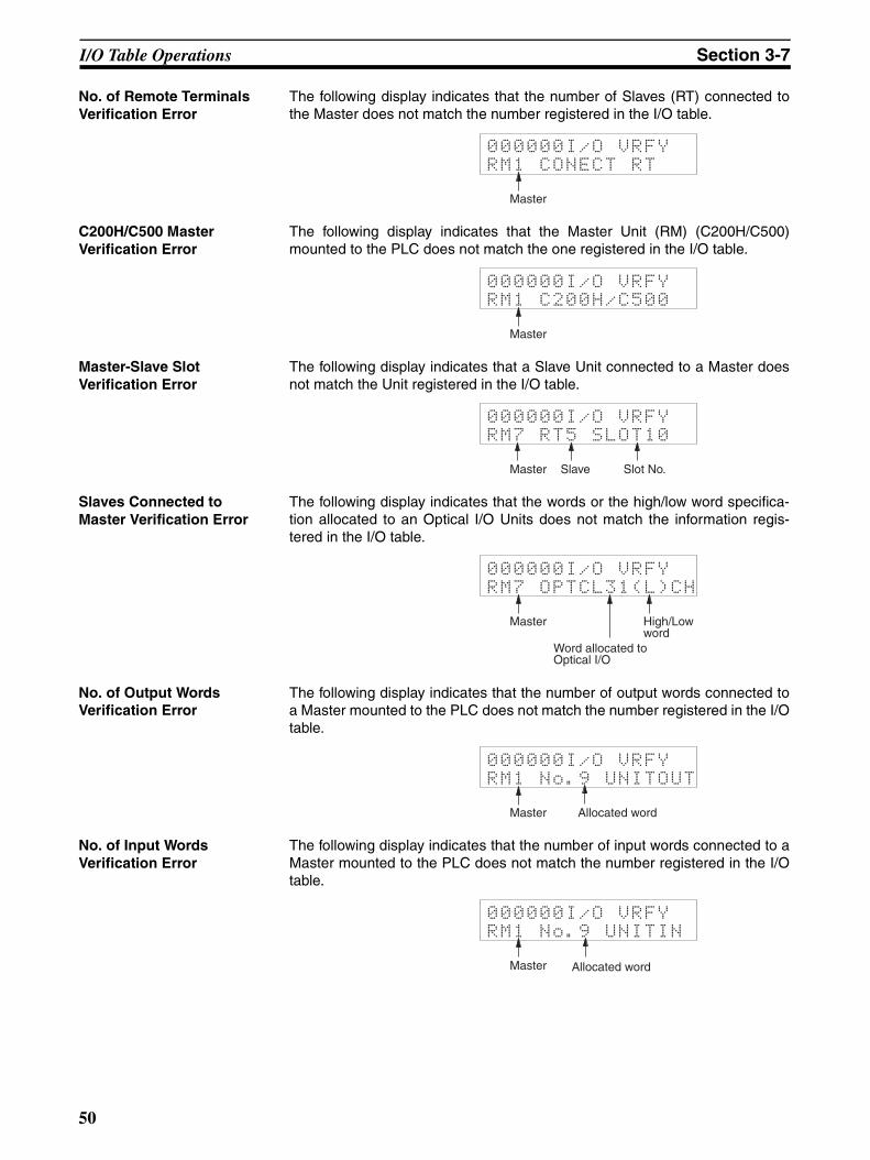
I/O Table Operations Section 3-7
No. of Remote Terminals Verification Error
The following display indicates that the number of Slaves (RT) connected tothe Master does not match the number registered in the I/O table.
C200H/C500 Master Verification Error
The following display indicates that the Master Unit (RM) (C200H/C500)mounted to the PLC does not match the one registered in the I/O table.
Master-Slave Slot Verification Error
The following display indicates that a Slave Unit connected to a Master doesnot match the Unit registered in the I/O table.
Slaves Connected to Master Verification Error
The following display indicates that the words or the high/low word specifica-tion allocated to an Optical I/O Units does not match the information regis-tered in the I/O table.
No. of Output Words Verification Error
The following display indicates that the number of output words connected toa Master mounted to the PLC does not match the number registered in the I/Otable.
No. of Input Words Verification Error
The following display indicates that the number of input words connected to aMaster mounted to the PLC does not match the number registered in the I/Otable.
000000I/O VRFY
RM1 CONECT RT
Master
000000I/O VRFY
RM1 C200H/C500
Master
000000I/O VRFY
RM7 RT5 SLOT10
Master Slave Slot No.
000000I/O VRFY
RM7 OPTCL31(L)CH
Master
Word allocated to Optical I/O
High/Low word
000000I/O VRFY
RM1 No.9 UNITOUT
Master Allocated word
000000I/O VRFY
RM1 No.9 UNITIN
Master Allocated word
50

I/O Table Operations Section 3-7
CS1 CPU Bus Unit Verification Error
The following display indicates that the type of a CS/CJ CPU Bus Unit (CPUBus Unit) mounted to the PLC does not match the type registered in the I/Otable.
000000I/O VRFY
CPU BU No.31
Unit number of CPU Bus Unit
51

53
SECTION 4Writing and Editing Programs
This section describes how to create and edit programs from the Programming Console.
4-1 Inputting Instructions . . . . . . . . . . . . . . . . . . . . . . . . . . . . . . . . . . . . . . . . . . . 54
4-1-1 Procedure for Inputting Instructions. . . . . . . . . . . . . . . . . . . . . . . . . 54
4-1-2 Inputting Basic Instructions . . . . . . . . . . . . . . . . . . . . . . . . . . . . . . . 55
4-1-3 Inputting Timer/Counter Instructions: TIM/CNT. . . . . . . . . . . . . . . 59
4-1-4 Inputting Special Instructions . . . . . . . . . . . . . . . . . . . . . . . . . . . . . . 62
4-2 Reading and Searching Programs . . . . . . . . . . . . . . . . . . . . . . . . . . . . . . . . . . 67
4-2-1 Reading Designated Addresses. . . . . . . . . . . . . . . . . . . . . . . . . . . . . 67
4-2-2 Instruction Search . . . . . . . . . . . . . . . . . . . . . . . . . . . . . . . . . . . . . . . 68
4-2-3 Bit Search . . . . . . . . . . . . . . . . . . . . . . . . . . . . . . . . . . . . . . . . . . . . . 69
4-3 Editing Programs. . . . . . . . . . . . . . . . . . . . . . . . . . . . . . . . . . . . . . . . . . . . . . . 71
4-3-1 Instruction Change . . . . . . . . . . . . . . . . . . . . . . . . . . . . . . . . . . . . . . 71
4-3-2 Instruction Insert . . . . . . . . . . . . . . . . . . . . . . . . . . . . . . . . . . . . . . . . 72
4-3-3 Instruction Delete . . . . . . . . . . . . . . . . . . . . . . . . . . . . . . . . . . . . . . . 73
4-3-4 Bit Address Change . . . . . . . . . . . . . . . . . . . . . . . . . . . . . . . . . . . . . 74
4-3-5 N.O./N.C. Change. . . . . . . . . . . . . . . . . . . . . . . . . . . . . . . . . . . . . . . 74
4-3-6 Instruction Variation Change . . . . . . . . . . . . . . . . . . . . . . . . . . . . . . 75
4-3-7 Timer/Counter SV Changes . . . . . . . . . . . . . . . . . . . . . . . . . . . . . . . 76
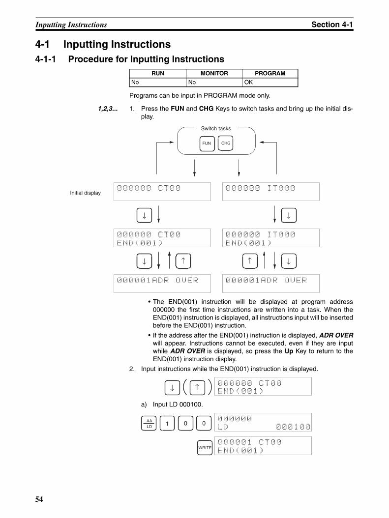
Inputting Instructions Section 4-1
4-1 Inputting Instructions4-1-1 Procedure for Inputting Instructions
Programs can be input in PROGRAM mode only.
1,2,3... 1. Press the FUN and CHG Keys to switch tasks and bring up the initial dis-play.
• The END(001) instruction will be displayed at program address000000 the first time instructions are written into a task. When theEND(001) instruction is displayed, all instructions input will be insertedbefore the END(001) instruction.
• If the address after the END(001) instruction is displayed, ADR OVERwill appear. Instructions cannot be executed, even if they are inputwhile ADR OVER is displayed, so press the Up Key to return to theEND(001) instruction display.
2. Input instructions while the END(001) instruction is displayed.
a) Input LD 000100.
RUN MONITOR PROGRAM
No No OK
↓↑
000000 CT00
000000 CT00
END(001)
000001ADR OVER 000001ADR OVER
000000 IT000
000000 IT000
END(001)
↓ ↑
↓ ↓
Initial display
FUN
Switch tasks
CHG
↓ ↑000000 CT00
END(001)
AALD 1 0 0
000000
LD 000100
WRITE000001 CT00
END(001)
54
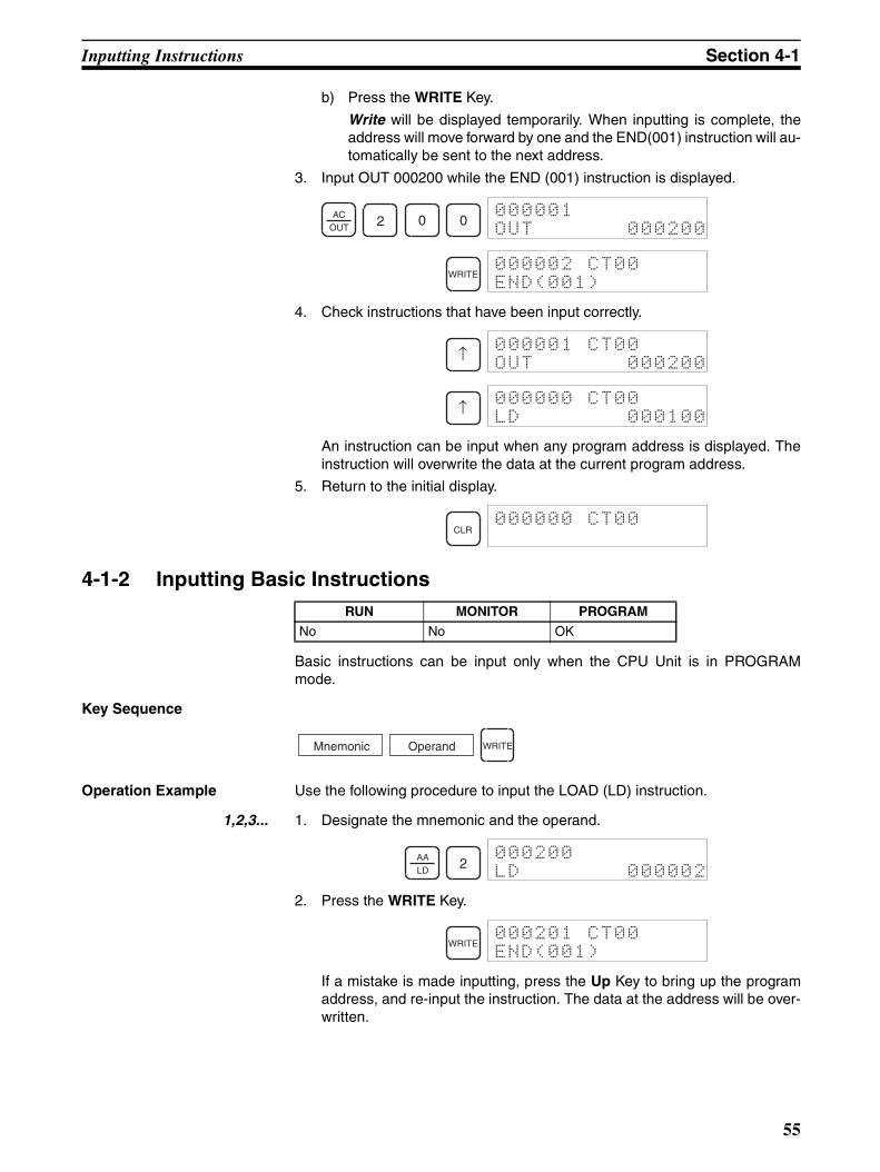
Inputting Instructions Section 4-1
b) Press the WRITE Key.
Write will be displayed temporarily. When inputting is complete, theaddress will move forward by one and the END(001) instruction will au-tomatically be sent to the next address.
3. Input OUT 000200 while the END (001) instruction is displayed.
4. Check instructions that have been input correctly.
An instruction can be input when any program address is displayed. Theinstruction will overwrite the data at the current program address.
5. Return to the initial display.
4-1-2 Inputting Basic Instructions
Basic instructions can be input only when the CPU Unit is in PROGRAMmode.
Key Sequence
Operation Example Use the following procedure to input the LOAD (LD) instruction.
1,2,3... 1. Designate the mnemonic and the operand.
2. Press the WRITE Key.
If a mistake is made inputting, press the Up Key to bring up the programaddress, and re-input the instruction. The data at the address will be over-written.
ACOUT 2 0 0
000001
OUT 000200
WRITE000002 CT00
END(001)
↑000001 CT00
OUT 000200
↑000000 CT00
LD 000100
CLR000000 CT00
RUN MONITOR PROGRAM
No No OK
Mnemonic WRITEOperand
AALD
2000200
LD 000002
WRITE000201 CT00
END(001)
55

Inputting Instructions Section 4-1
Inputting Basic Instructions
Designating Bit Addresses
Mnemonic Key sequence Mnemonic Key sequence
LD OR LD
LD NOT AND LD
OR OUT
OR NOT OUT NOT
AND SET
AND NOT RSET
Bit type Key sequence Display example
CIO bits
Work bits (WR)
Holding bits (HR)
Auxiliary bits (AR)
Timer bits
Counter bits
AALD
STOR
AALD
NOTAALD
TNAND
AALD
STOR
ACOUT
NOTSTOR NOT
ACOUT
TNAND
FUNSET
NOTTN
AND FUNRESET
Number Bit 15 of CIO 0000
000000
LD 000015
Number*EMWR/LR
Bit 15 of W000
000000
LD W00015
NumberARHR
Bit 15 of H000
000000
LD H00015
NumberSHIFTARHR
Bit 15 of A000
000000
LD A00015
TIM NumberT0015
000000
LD T0015
NumberTK
CNT
C0015
000000
LD C0015
56
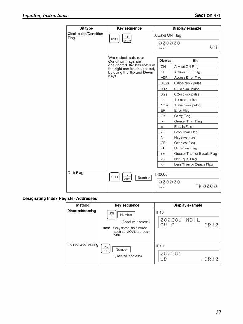
Inputting Instructions Section 4-1
Designating Index Register Addresses
Clock pulse/Condition Flag
Task Flag
Method Key sequence Display example
Direct addressing
Indirect addressing
Bit type Key sequence Display example
SHIFTCF
SRCH
Always ON Flag
000000LD ON
When clock pulses or Condition Flags are designated, the bits listed at the right can be designated, by using the Up and Down Keys.
ON Always ON Flag
OFF Always OFF Flag
AER Access Error Flag
0.02s 0.02-s clock pulse
0.1s 0.1-s clock pulse
0.2s 0.2-s clock pulse
1s 1-s clock pulse
1min 1-min clock pulse
ER Error Flag
CY Carry Flag
> Greater Than Flag
= Equals Flag
< Less Than Flag
N Negative Flag
OF Overflow Flag
UF Underflow Flag
>= Greater Than or Equals Flag
<> Not Equal Flag
<= Less Than or Equals Flag
Display Bit
SHIFT NumberTK
CNT
TK0000
000000LD TK0000
Number
(Absolute address)
DRIR
Note Only some instructions such as MOVL are possible.
-
IR10
000201 MOVL
SV A IR10
Number
(Relative address)
,IR+,IR
IR10
000201
LD ,IR10
57
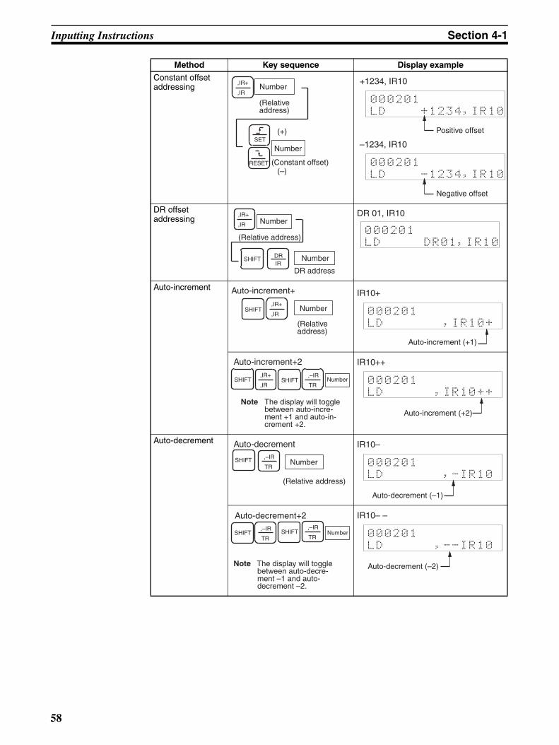
Inputting Instructions Section 4-1
Constant offset addressing
DR offset addressing
Auto-increment
Auto-decrement
Method Key sequence Display example
Number
(Relative address)
,IR+
,IR
SET
RESET
Number
(Constant offset)
(+)
(–)
+1234, IR10
000201
LD +1234,IR10
Positive offset
–1234, IR10
000201
LD -1234,IR10
Negative offset
Number
(Relative address)
Number
DR address
,IR+
,IR
SHIFT DRIR
DR 01, IR10
000201
LD DR01,IR10
Number
(Relative address)
Auto-increment+
SHIFT,IR+
,IR
IR10+
000201
LD ,IR10+
Auto-increment (+1)
Note The display will toggle between auto-incre-ment +1 and auto-in-crement +2.
Auto-increment+2,IR+
,IR
,–IR
TRSHIFT SHIFT Number
IR10++
000201
LD ,IR10++
Auto-increment (+2)
SHIFT ,–IR
TR
Auto-decrement
Number
(Relative address)
IR10–
000201
LD ,-IR10
Auto-decrement (–1)
Note The display will toggle between auto-decre-ment –1 and auto-decrement –2.
SHIFT,–IR
TRNumber
,–IR
TRSHIFT
Auto-decrement+2 IR10– –
000201
LD ,--IR10
Auto-decrement (–2)
58

Inputting Instructions Section 4-1
Designating Instruction Variations
4-1-3 Inputting Timer/Counter Instructions: TIM/CNT
Timer/counter instructions can be input when the CPU Unit is in PROGRAMmode.
Key Sequence
Operation Example The following example describes how to input TIM 0010 with a SV of 10 s.
1,2,3... 1. Press the TIM Key and input the timer number.
2. Input the set value. In the following example, the set value is #0100 (10 s).
Variation Key sequence Display example
Differentiate up
Differentiate down
Immediate refresh
RUN MONITOR PROGRAM
No No OK
Note The same key sequence can be used to reset.
SHIFTSET
000123 CT00
@LD 000000
Symbol: Differentiate up
Note The same key se-quence can be used to reset.
SHIFTRESET
000123 CT00
%LD 000000
Symbol: Differentiate down
Note The same key se-quence can be used to reset.
!TEXT 000123 CT00
!LD 000000
Symbol: Immediate refresh
000123 CT00
!@LD 000000
Symbols: Immediate refresh/Differentiate up
000123 CT00
!%LD 000000
Symbols: Immediate refresh/Differentiate down
TC number WRITETK
CNT
TIM
SV
TIM 1 0000201 CT00
TIM 0010
↓000201 TIM
SV #0000
1 0 0000201 TIM
SV #0100
59
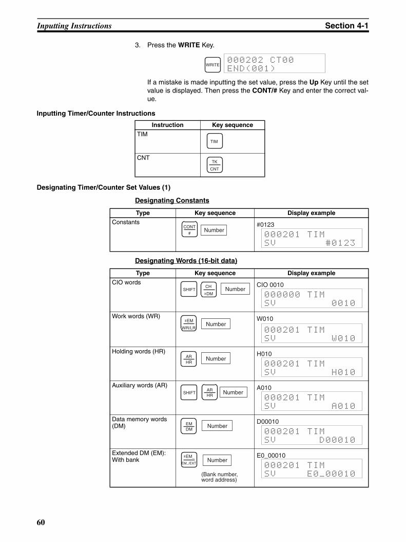
Inputting Instructions Section 4-1
3. Press the WRITE Key.
If a mistake is made inputting the set value, press the Up Key until the setvalue is displayed. Then press the CONT/# Key and enter the correct val-ue.
Inputting Timer/Counter Instructions
Designating Timer/Counter Set Values (1)
Designating Constants
Designating Words (16-bit data)
WRITE000202 CT00
END(001)
Instruction Key sequence
TIM
CNT
TIM
TK
CNT
Type Key sequence Display example
ConstantsNumber
CONT
#
#0123
000201 TIM
SV #0123
Type Key sequence Display example
CIO words
Work words (WR)
Holding words (HR)
Auxiliary words (AR)
Data memory words (DM)
Extended DM (EM): With bank
NumberSHIFTCH
*DM
CIO 0010
000000 TIM
SV 0010
Number*EM
WR/LR
W010
000201 TIM
SV W010
NumberARHR
H010
000201 TIM
SV H010
NumberARHR
SHIFTA010
000201 TIM
SV A010
NumberEMDM
D00010
000201 TIM
SV D00010
Number
(Bank number, word address)
*EM_
EM_/EXT
E0_00010
000201 TIM
SV E0_00010
60
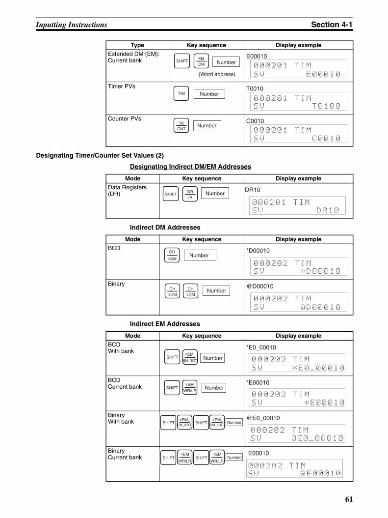
Inputting Instructions Section 4-1
Designating Timer/Counter Set Values (2)
Designating Indirect DM/EM Addresses
Indirect DM Addresses
Indirect EM Addresses
Extended DM (EM): Current bank
Timer PVs
Counter PVs
Type Key sequence Display example
Number
(Word address)
SHIFT EMDM
E00010
000201 TIM
SV E00010
TIM NumberT0010
000201 TIM
SV T0100
NumberTKCNT
C0010
000201 TIM
SV C0010
Mode Key sequence Display example
Data Registers (DR) NumberSHIFT DR
IR
DR10
000201 TIM
SV DR10
Mode Key sequence Display example
BCD
Binary
NumberCH
*DM
*D00010
000202 TIM
SV *D00010
NumberCH CH*DM *DM
@D00010
000202 TIM
SV @D00010
Mode Key sequence Display example
BCDWith bank
BCDCurrent bank
BinaryWith bank
BinaryCurrent bank
Number*EM_
EM_/EXTSHIFT
*E0_00010
000202 TIM
SV *E0_00010
NumberSHIFTWR/LR
*EM *E00010
000202 TIM
SV *E00010
NumberEM_/EXTSHIFT EM_/EXTSHIFT*EM_ *EM_ @E0_00010
000202 TIM
SV @E0_00010
NumberSHIFT SHIFTWR/LR WR/LR
*EM *EM E00010
SV @E00010
000202 TIM
61
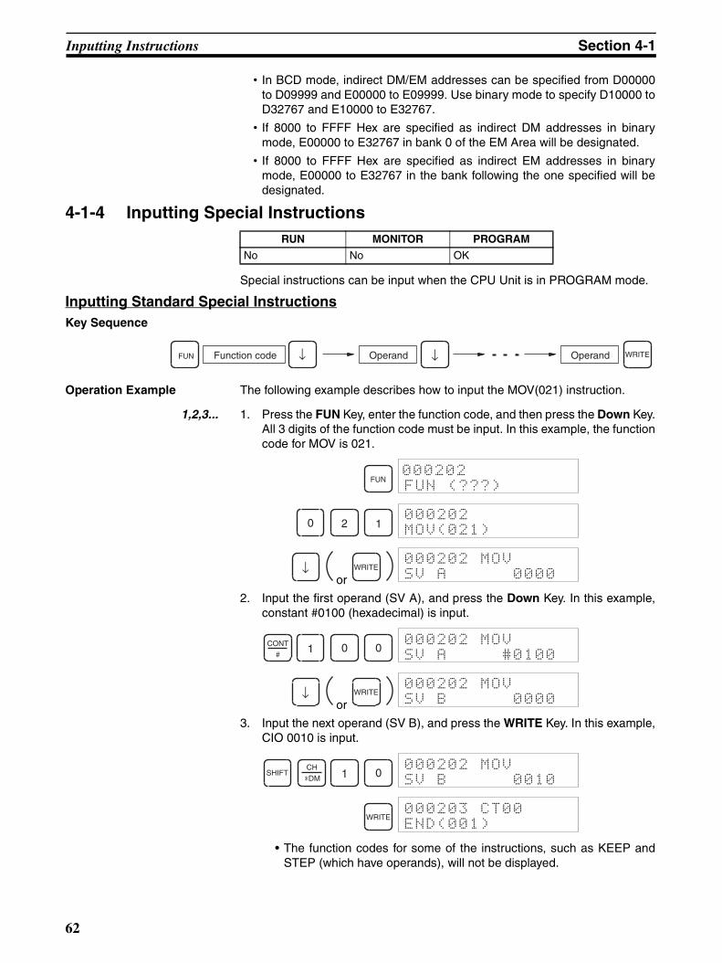
Inputting Instructions Section 4-1
• In BCD mode, indirect DM/EM addresses can be specified from D00000to D09999 and E00000 to E09999. Use binary mode to specify D10000 toD32767 and E10000 to E32767.
• If 8000 to FFFF Hex are specified as indirect DM addresses in binarymode, E00000 to E32767 in bank 0 of the EM Area will be designated.
• If 8000 to FFFF Hex are specified as indirect EM addresses in binarymode, E00000 to E32767 in the bank following the one specified will bedesignated.
4-1-4 Inputting Special Instructions
Special instructions can be input when the CPU Unit is in PROGRAM mode.
Inputting Standard Special InstructionsKey Sequence
Operation Example The following example describes how to input the MOV(021) instruction.
1,2,3... 1. Press the FUN Key, enter the function code, and then press the Down Key.All 3 digits of the function code must be input. In this example, the functioncode for MOV is 021.
or
2. Input the first operand (SV A), and press the Down Key. In this example,constant #0100 (hexadecimal) is input.
or
3. Input the next operand (SV B), and press the WRITE Key. In this example,CIO 0010 is input.
• The function codes for some of the instructions, such as KEEP andSTEP (which have operands), will not be displayed.
RUN MONITOR PROGRAM
No No OK
Function code WRITEFUN ↓Operand Operand↓
FUN000202
FUN (???)
0 2 1000202
MOV(021)
↓ WRITE000202 MOV
SV A 0000
CONT
#1 0 0
000202 MOV
SV A #0100
↓ WRITE000202 MOV
SV B 0000
SHIFTCH
*DM 1 0000202 MOV
SV B 0010
WRITE000203 CT00
END(001)
62

Inputting Instructions Section 4-1
• For further information of the following instruction variations, refer topage 102.
Inputting Symbol Comparison Instructions
Key Sequence
Operation Example The following example describes how to input the <= instruction.
1,2,3... 1. Press the FUN Key and enter the function code. The function code for <=is 318.
2. Specify the logic type. In this example, OR.
3. Press the Down Key.
or
4. Input the first operand (SV A), and press the Down Key. In this example,constant #00000010.
or
5. Input the next operand (SV B), and press the WRITE Key. In this example,CIO 0011 is used.
Function codeFUN OperandLogic WRITEOperand
FUN000202
FUN (???)
3 1 8000202
[LD] <=SL(318)
ST
OR
000202
[OR] <=SL(318)
↓ WRITE000202 <=SL
SV A 0000
CONT
#1 0
000202 <=SL
SV A #00000010
↓ WRITE000202 <=SL
SV B 0000
1 1000202 <=SL
SV B 0011
WRITE000203 CT00
END(001)
63
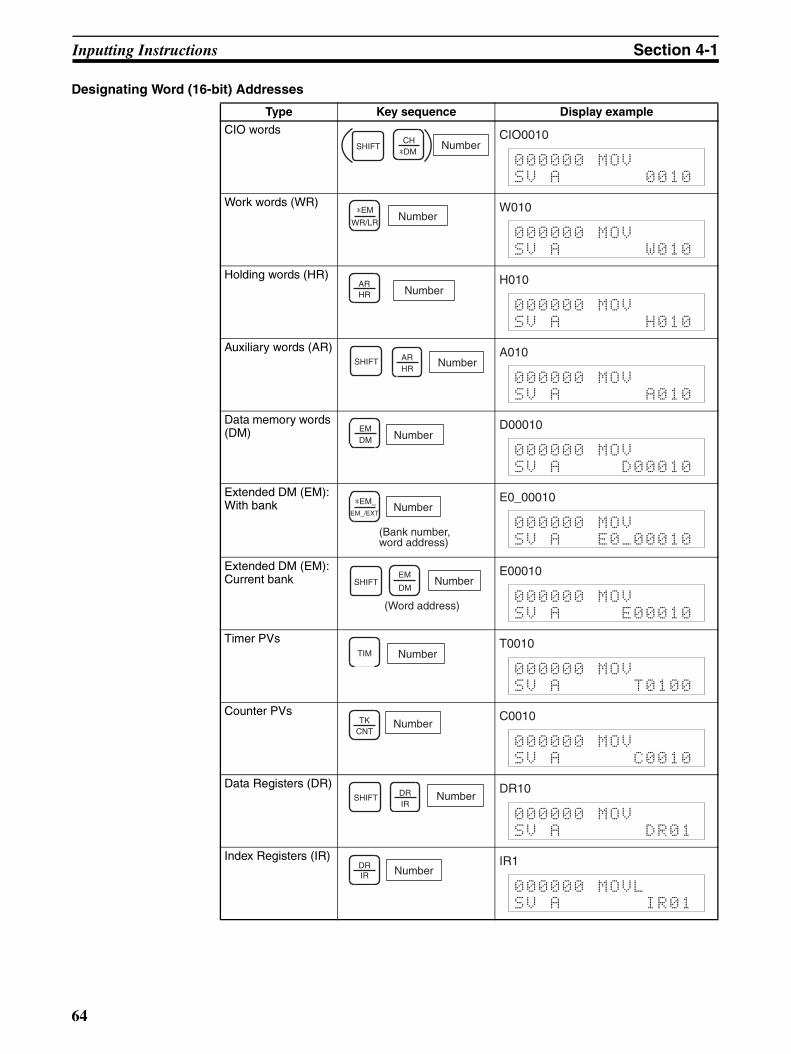
Inputting Instructions Section 4-1
Designating Word (16-bit) Addresses
Type Key sequence Display example
CIO words
Work words (WR)
Holding words (HR)
Auxiliary words (AR)
Data memory words (DM)
Extended DM (EM): With bank
Extended DM (EM): Current bank
Timer PVs
Counter PVs
Data Registers (DR)
Index Registers (IR)
NumberSHIFTCH*DM
CIO0010
000000 MOV
SV A 0010
NumberWR/LR
*EM W010
000000 MOV
SV A W010
NumberARHR
H010
000000 MOV
SV A H010
NumberARHR
SHIFTA010
000000 MOV
SV A A010
NumberEMDM
D00010
000000 MOV
SV A D00010
Number
(Bank number, word address)
EM_/EXT
*EM_ E0_00010
000000 MOV
SV A E0_00010
Number
(Word address)
SHIFTEM
DM
E00010
000000 MOV
SV A E00010
TIM NumberT0010
000000 MOV
SV A T0100
NumberTKCNT
C0010
000000 MOV
SV A C0010
NumberSHIFT DRIR
DR10
000000 MOV
SV A DR01
NumberDRIR
IR1
000000 MOVL
SV A IR01
64

Inputting Instructions Section 4-1
Designating Indirect DM/EM Addresses
Indirect DM Addresses
Indirect EM Addresses
• In BCD mode, indirect DM/EM addresses can be specified from D00000to D09999 and E00000 to E09999. Use binary mode to specify D10000 toD32767 and E10000 to E32767.
• If 8000 to FFFF Hex are specified as indirect DM addresses in binarymode, E00000 to E32767 in bank 0 of the EM Area will be designated.
• If 8000 to FFFF Hex are specified as indirect EM addresses in binarymode, E00000 to E32767 in the bank following the one specified will bedesignated.
Mode Key sequence Display example
BCD
Binary
NumberCH*DM
*D00010
000202 MOV
SV A *D00010
NumberCH CH*DM *DM
@D00010
000202 MOV
SV A @D00010
Mode Key sequence Display example
BCDWith bank
BCDCurrent bank
BinaryWith bank
BinaryCurrent bank
Number*EM_EM_/EXT
SHIFT*E0_00010
000202 MOV
SV A *E0_00010
NumberSHIFTWR/LR*EM *E00010
000202 MOV
SV A *E00010
NumberEM_/EXT
SHIFT SHIFT*EM_
EM_/EXT
*EM_ @E0_00010
000202 MOV
SV A @E0_00010
NumberSHIFT SHIFTWR/LR*EM
WR/LR*EM @E00010
000202 MOV
SV A @E00010
65
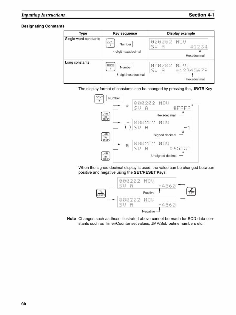
Inputting Instructions Section 4-1
Designating Constants
The display format of constants can be changed by pressing the,–IR/TR Key.
When the signed decimal display is used, the value can be changed betweenpositive and negative using the SET/RESET Keys.
Note Changes such as those illustrated above cannot be made for BCD data con-stants such as Timer/Counter set values, JMP/Subroutine numbers etc.
Type Key sequence Display example
Single-word constants
Long constants
Number
4-digit hexadecimal
CONT#
000202 MOV
SV A #1234
Hexadecimal
Number
8-digit hexadecimal
CONT#
000202 MOVL
SV A #12345678
Hexadecimal
000202 MOV
SV A #FFFF
Hexadecimal
Number
#
000202 MOV
SV A -1
Signed decimal
+(–)
000202 MOV
SV A &65535
Unsigned decimal
&
,–IRTRDISP
CONT#
,–IRTRDISP
,–IRTRDISP
000202 MOV
SV A +4660
Positive
000202 MOV
SV A -4660
Negative
SETRESET
66
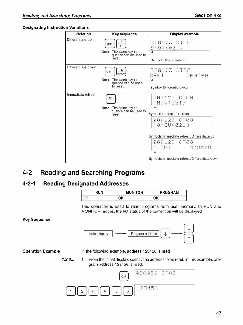
Reading and Searching Programs Section 4-2
Designating Instruction Variations
4-2 Reading and Searching Programs
4-2-1 Reading Designated Addresses
This operation is used to read programs from user memory. In RUN andMONITOR modes, the I/O status of the current bit will be displayed.
Key Sequence
Operation Example In the following example, address 123456 is read.
1,2,3... 1. From the initial display, specify the address to be read. In this example, pro-gram address 123456 is read.
…
Variation Key sequence Display example
Differentiate up
Differentiate down
Immediate refresh
RUN MONITOR PROGRAM
OK OK OK
Note The same key se-quence can be used to reset.
SHIFTSET
000123 CT00
@MOV(021)
Symbol: Differentiate up
Note The same key se-quence can be used to reset.
SHIFTRESET
000123 CT00
%SET 000000
Symbol: Differentiate down
Note The same key se-quence can be used to reset.
!TEXT 000123 CT00
!MOV(021)
Symbol: Immediate refresh
000123 CT00
!@MOV(021)
Symbols: Immediate refresh/Differentiate up
000123 CT00
!%SET 000000
Symbols: Immediate refresh/Differentiate down
Program addressInitial display ↓↓
↑
CLR000000 CT00
1 2 3 4 5 6123456
67
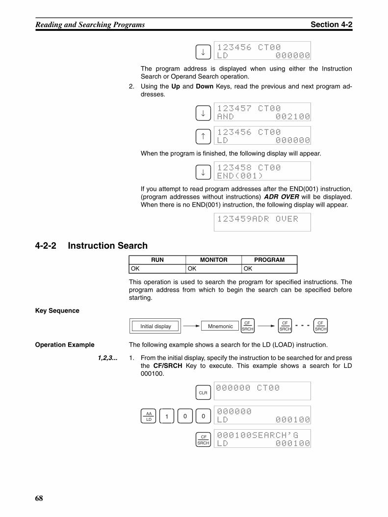
Reading and Searching Programs Section 4-2
The program address is displayed when using either the InstructionSearch or Operand Search operation.
2. Using the Up and Down Keys, read the previous and next program ad-dresses.
When the program is finished, the following display will appear.
If you attempt to read program addresses after the END(001) instruction,(program addresses without instructions) ADR OVER will be displayed.When there is no END(001) instruction, the following display will appear.
4-2-2 Instruction Search
This operation is used to search the program for specified instructions. Theprogram address from which to begin the search can be specified beforestarting.
Key Sequence
Operation Example The following example shows a search for the LD (LOAD) instruction.
1,2,3... 1. From the initial display, specify the instruction to be searched for and pressthe CF/SRCH Key to execute. This example shows a search for LD000100.
↓123456 CT00
LD 000000
↓123457 CT00
AND 002100
↑123456 CT00
LD 000000
↓123458 CT00
END(001)
123459ADR OVER
RUN MONITOR PROGRAM
OK OK OK
Initial display MnemonicCF
SRCH
CF
SRCH
CF
SRCH
CLR000000 CT00
AALD 1 0 0
000000
LD 000100
CF
SRCH
000100SEARCH'G
LD 000100
68
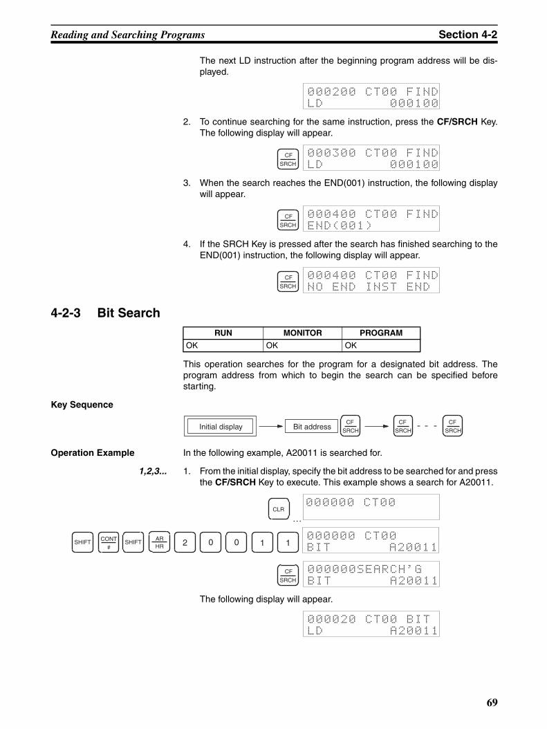
Reading and Searching Programs Section 4-2
The next LD instruction after the beginning program address will be dis-played.
2. To continue searching for the same instruction, press the CF/SRCH Key.The following display will appear.
3. When the search reaches the END(001) instruction, the following displaywill appear.
4. If the SRCH Key is pressed after the search has finished searching to theEND(001) instruction, the following display will appear.
4-2-3 Bit Search
This operation searches for the program for a designated bit address. Theprogram address from which to begin the search can be specified beforestarting.
Key Sequence
Operation Example In the following example, A20011 is searched for.
1,2,3... 1. From the initial display, specify the bit address to be searched for and pressthe CF/SRCH Key to execute. This example shows a search for A20011.
…
The following display will appear.
000200 CT00 FIND
LD 000100
CF
SRCH
000300 CT00 FIND
LD 000100
CF
SRCH
000400 CT00 FIND
END(001)
CF
SRCH
000400 CT00 FIND
NO END INST END
RUN MONITOR PROGRAM
OK OK OK
Initial display Bit addressCF
SRCH
CF
SRCH
CF
SRCH
CLR000000 CT00
SHIFT CONT
#SHIFT
ARHR 2 0 0 1 1
000000 CT00
BIT A20011
CF
SRCH
000000SEARCH'G
BIT A20011
000020 CT00 BIT
LD A20011
69
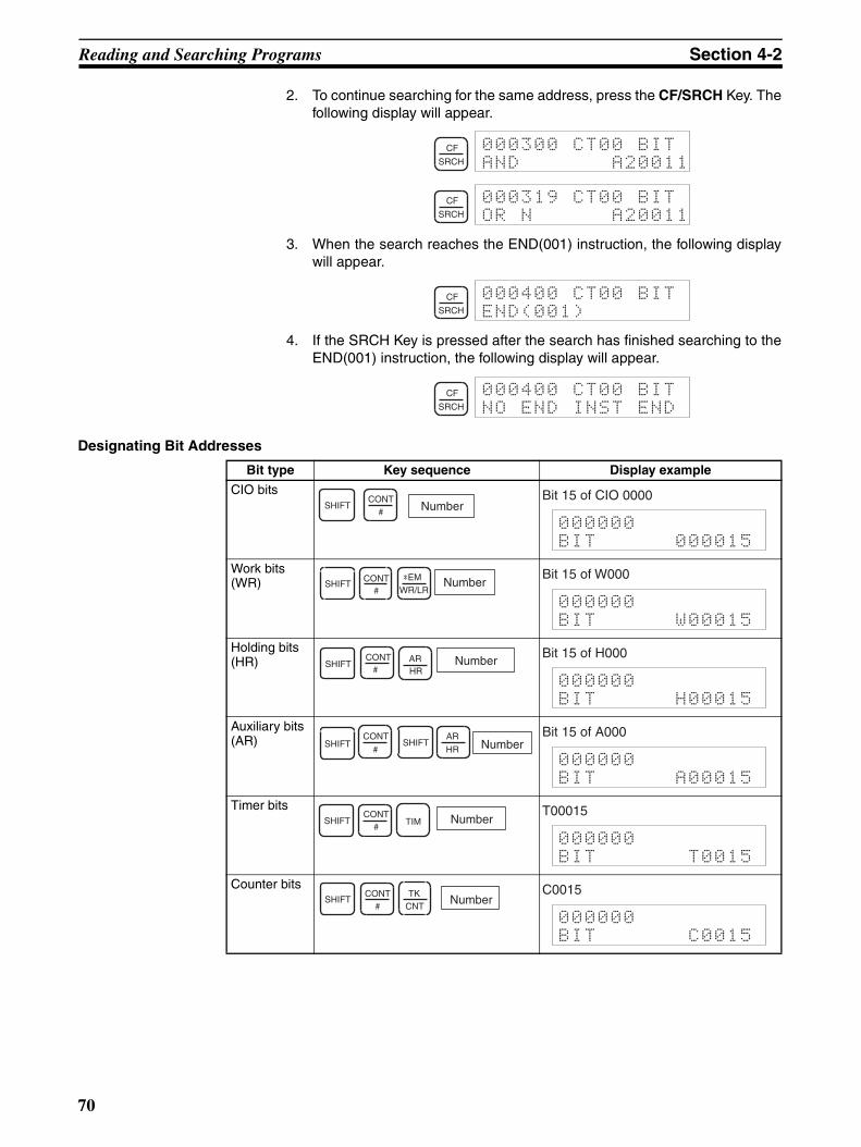
Reading and Searching Programs Section 4-2
2. To continue searching for the same address, press the CF/SRCH Key. Thefollowing display will appear.
3. When the search reaches the END(001) instruction, the following displaywill appear.
4. If the SRCH Key is pressed after the search has finished searching to theEND(001) instruction, the following display will appear.
Designating Bit Addresses
CF
SRCH
000300 CT00 BIT
AND A20011
CF
SRCH
000319 CT00 BIT
OR N A20011
CF
SRCH
000400 CT00 BIT
END(001)
CF
SRCH
000400 CT00 BIT
NO END INST END
Bit type Key sequence Display example
CIO bits
Work bits (WR)
Holding bits (HR)
Auxiliary bits (AR)
Timer bits
Counter bits
NumberSHIFTCONT
#
Bit 15 of CIO 0000
000000
BIT 000015
NumberSHIFTCONT
# WR/LR*EM Bit 15 of W000
000000
BIT W00015
NumberSHIFTARHR
CONT#
Bit 15 of H000
000000
BIT H00015
NumberAR
HRSHIFT SHIFT
CONT
#
Bit 15 of A000
000000
BIT A00015
NumberSHIFT TIMCONT
#
T00015
000000
BIT T0015
NumberSHIFTTK
CNTCONT
#
C0015
000000
BIT C0015
70
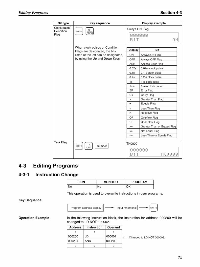
Editing Programs Section 4-3
4-3 Editing Programs
4-3-1 Instruction Change
This operation is used to overwrite instructions in user programs.
Key Sequence
Operation Example In the following instruction block, the instruction for address 000200 will bechanged to LD NOT 000002.
Clock pulse/Condition Flag
Task Flag
RUN MONITOR PROGRAM
No No OK
Bit type Key sequence Display example
SHIFTCF
SRCH
Always ON Flag
000000
BIT ON
When clock pulses or Condition Flags are designated, the bits listed at the left can be designated, by using the Up and Down Keys.
ON Always ON Flag
OFF Always OFF Flag
AER Access Error Flag
0.02s 0.02-s clock pulse
0.1s 0.1-s clock pulse
0.2s 0.2-s clock pulse
1s 1-s clock pulse
1min 1-min clock pulse
ER Error Flag
CY Carry Flag
> Greater Than Flag
= Equals Flag
< Less Than Flag
N Negative Flag
OF Overflow Flag
UF Underflow Flag
>= Greater Than or Equals Flag
<> Not Equal Flag
<= Less Than or Equals Flag
Display Bit
SHIFT NumberTKCNT
TK0000
000000
BIT TK0000
Program address display Input mnemonic WRITE
Address Instruction Operand
: : :
000200 LD 000001
000201 AND 000200
: : :
Changed to LD NOT 000002.
71
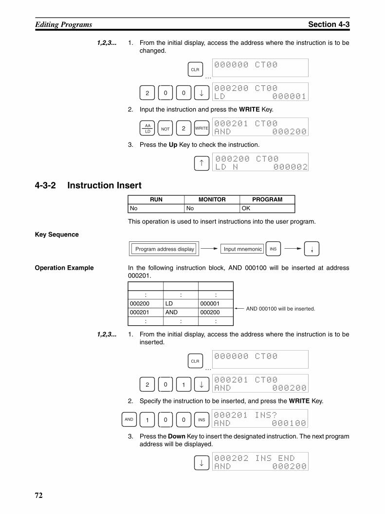
Editing Programs Section 4-3
1,2,3... 1. From the initial display, access the address where the instruction is to bechanged.
…
2. Input the instruction and press the WRITE Key.
3. Press the Up Key to check the instruction.
4-3-2 Instruction Insert
This operation is used to insert instructions into the user program.
Key Sequence
Operation Example In the following instruction block, AND 000100 will be inserted at address000201.
1,2,3... 1. From the initial display, access the address where the instruction is to beinserted.
…
2. Specify the instruction to be inserted, and press the WRITE Key.
3. Press the Down Key to insert the designated instruction. The next programaddress will be displayed.
CLR000000 CT00
2 0 0 ↓000200 CT00
LD 000001
AALD NOT 2 WRITE
000201 CT00
AND 000200
↑000200 CT00
LD N 000002
RUN MONITOR PROGRAM
No No OK
Program address display Input mnemonic INS
: : :
000200 LD 000001
000201 AND 000200
: : :
AND 000100 will be inserted.
CLR000000 CT00
2 0 1 ↓000201 CT00
AND 000200
AND 1 0 0 INS000201 INS?
AND 000100
↓000202 INS END
AND 000200
72
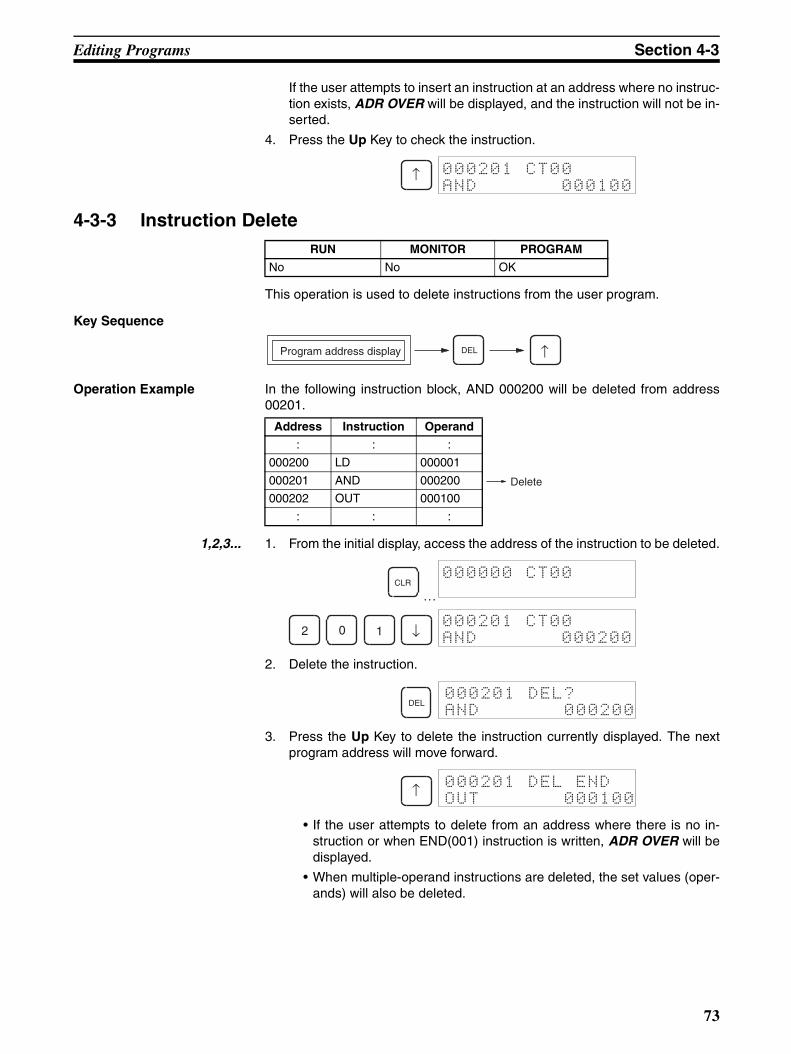
Editing Programs Section 4-3
If the user attempts to insert an instruction at an address where no instruc-tion exists, ADR OVER will be displayed, and the instruction will not be in-serted.
4. Press the Up Key to check the instruction.
4-3-3 Instruction Delete
This operation is used to delete instructions from the user program.
Key Sequence
Operation Example In the following instruction block, AND 000200 will be deleted from address00201.
1,2,3... 1. From the initial display, access the address of the instruction to be deleted.
…
2. Delete the instruction.
3. Press the Up Key to delete the instruction currently displayed. The nextprogram address will move forward.
• If the user attempts to delete from an address where there is no in-struction or when END(001) instruction is written, ADR OVER will bedisplayed.
• When multiple-operand instructions are deleted, the set values (oper-ands) will also be deleted.
↑ 000201 CT00
AND 000100
RUN MONITOR PROGRAM
No No OK
Program address display DEL ↑
Address Instruction Operand
: : :
000200 LD 000001
000201 AND 000200
000202 OUT 000100
: : :
Delete
CLR000000 CT00
2 0 1 ↓000201 CT00
AND 000200
DEL000201 DEL?
AND 000200
↑000201 DEL END
OUT 000100
73

Editing Programs Section 4-3
4-3-4 Bit Address Change
This operation is used to change bit addresses in operands in the user pro-gram.
Key Sequence
Operation Example In the following instruction block, the operand address at 000200,CIO 000001, will be changed to CIO 000002.
1,2,3... 1. From the initial display, access the address of the instruction containing thebit address to be changed.
…
2. Specify the new operand, and press the WRITE Key.
3. Press the Up Key to check the operand has been changed.
4-3-5 N.O./N.C. Change
This operation is used to change N.O. and N.C. conditions in the user pro-gram.
Key Sequence
RUN MONITOR PROGRAM
No No OK
Program address display Input operand address WRITE
Address Instruction Operands
: : :
000200 LD 000001
000201 AND 000200
: : :
The operand address will be changed to CIO 000002.
CLR000000 CT00
2 0 0 ↓000200 CT00
LD 000001
2000200 CT00
LD 000002
WRITE000201 CT00
AND 000200
↑000200 CT00
LD 000002
RUN MONITOR PROGRAM
No No OK
Program address display NOT WRITENOT
74
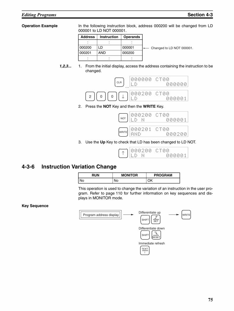
Editing Programs Section 4-3
Operation Example In the following instruction block, address 000200 will be changed from LD000001 to LD NOT 000001.
1,2,3... 1. From the initial display, access the address containing the instruction to bechanged.
…
2. Press the NOT Key and then the WRITE Key.
3. Use the Up Key to check that LD has been changed to LD NOT.
4-3-6 Instruction Variation Change
This operation is used to change the variation of an instruction in the user pro-gram. Refer to page 110 for further information on key sequences and dis-plays in MONITOR mode.
Key Sequence
Address Instruction Operands
: : :
000200 LD 000001
000201 AND 000200
: : :
Changed to LD NOT 000001.
CLR000000 CT00
LD 000000
2 0 0 ↓000200 CT00
LD 000001
NOT000200 CT00
LD N 000001
WRITE000201 CT00
AND 000200
↑000200 CT00
LD N 000001
RUN MONITOR PROGRAM
No No OK
Program address display WRITEDifferentiate up
Differentiate down
Immediate refresh
SHIFT
SHIFT
!
TEXT
SET
RESET
75
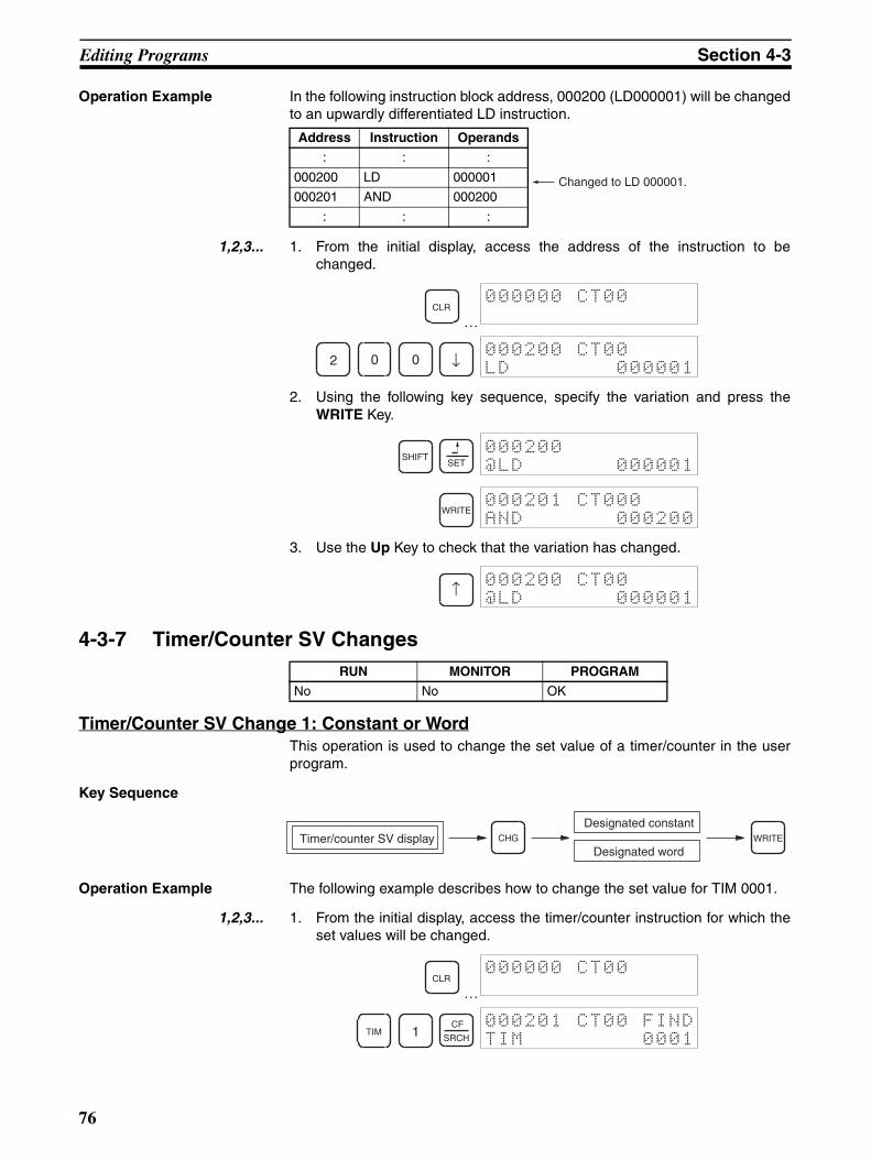
Editing Programs Section 4-3
Operation Example In the following instruction block address, 000200 (LD000001) will be changedto an upwardly differentiated LD instruction.
1,2,3... 1. From the initial display, access the address of the instruction to bechanged.
…
2. Using the following key sequence, specify the variation and press theWRITE Key.
3. Use the Up Key to check that the variation has changed.
4-3-7 Timer/Counter SV Changes
Timer/Counter SV Change 1: Constant or WordThis operation is used to change the set value of a timer/counter in the userprogram.
Key Sequence
Operation Example The following example describes how to change the set value for TIM 0001.
1,2,3... 1. From the initial display, access the timer/counter instruction for which theset values will be changed.
…
Address Instruction Operands
: : :
000200 LD 000001
000201 AND 000200
: : :
Changed to LD 000001.
CLR000000 CT00
2 0 0 ↓000200 CT00
LD 000001
SHIFTSET
000200
@LD 000001
WRITE000201 CT000
AND 000200
↑000200 CT00
@LD 000001
RUN MONITOR PROGRAM
No No OK
Timer/counter SV displayDesignated constant
WRITE
Designated wordCHG
CLR000000 CT00
TIM 1CF
SRCH
000201 CT00 FIND
TIM 0001
76
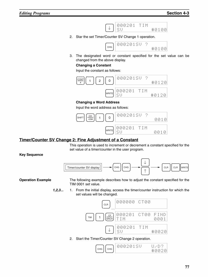
Editing Programs Section 4-3
2. Star the set Timer/Counter SV Change 1 operation.
3. The designated word or constant specified for the set value can bechanged from the above display.
Changing a Constant
Input the constant as follows:
Changing a Word Address
Input the word address as follows:
Timer/Counter SV Change 2: Fine Adjustment of a ConstantThis operation is used to increment or decrement a constant specified for theset value of a timer/counter in the user program.
Key Sequence
Operation Example The following example describes how to adjust the constant specified for theTIM 0001 set value.
1,2,3... 1. From the initial display, access the timer/counter instruction for which theset values will be changed.
…
2. Start the Timer/Counter SV Change 2 operation.
↓000201 TIM
SV #0100
CHG000201SV ?
#0100
CONT
#1 2 0
000201SV ?
#0120
WRITE000201 TIM
SV #0120
SHIFTCH
*DM 1 0000201SV ?
0010
WRITE000201 TIM
SV 0010
Timer/counter SV display CLRCLRCHGCHG WRITE
↓
↑
CLR000000 CT00
TIM 1CF
SRCH
000201 CT00 FIND
TIM 0001
↓000201 TIM
SV #0020
CHG CHG000201SV U/D?
#0020
77
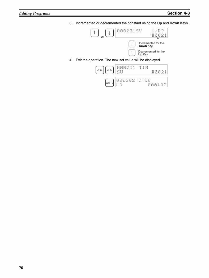
Editing Programs Section 4-3
3. Incremented or decremented the constant using the Up and Down Keys.
or
4. Exit the operation. The new set value will be displayed.
↑ ↓ 000201SV U/D?
#0021
Incremented for the Down Key.
Decremented for the Up Key.
↓
↑
CLR CLR000201 TIM
SV #0021
WRITE000202 CT00
LD 000100
78
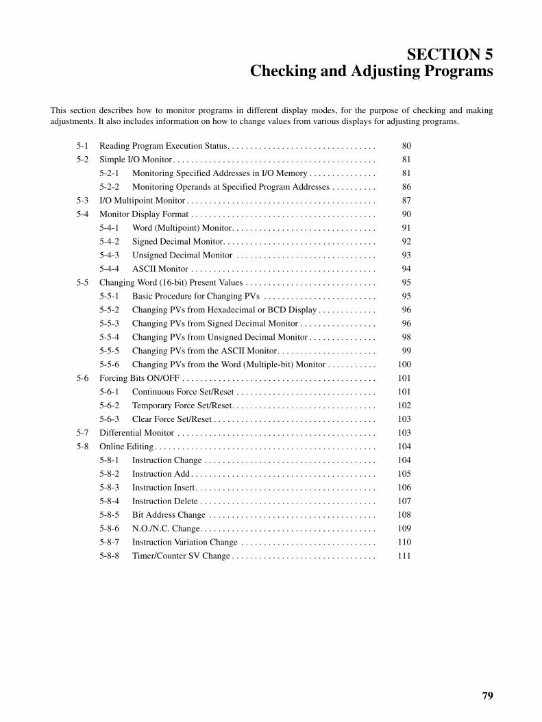
79
SECTION 5Checking and Adjusting Programs
This section describes how to monitor programs in different display modes, for the purpose of checking and makingadjustments. It also includes information on how to change values from various displays for adjusting programs.
5-1 Reading Program Execution Status. . . . . . . . . . . . . . . . . . . . . . . . . . . . . . . . . 80
5-2 Simple I/O Monitor . . . . . . . . . . . . . . . . . . . . . . . . . . . . . . . . . . . . . . . . . . . . . 81
5-2-1 Monitoring Specified Addresses in I/O Memory . . . . . . . . . . . . . . . 81
5-2-2 Monitoring Operands at Specified Program Addresses . . . . . . . . . . 86
5-3 I/O Multipoint Monitor . . . . . . . . . . . . . . . . . . . . . . . . . . . . . . . . . . . . . . . . . . 87
5-4 Monitor Display Format . . . . . . . . . . . . . . . . . . . . . . . . . . . . . . . . . . . . . . . . . 90
5-4-1 Word (Multipoint) Monitor. . . . . . . . . . . . . . . . . . . . . . . . . . . . . . . . 91
5-4-2 Signed Decimal Monitor. . . . . . . . . . . . . . . . . . . . . . . . . . . . . . . . . . 92
5-4-3 Unsigned Decimal Monitor . . . . . . . . . . . . . . . . . . . . . . . . . . . . . . . 93
5-4-4 ASCII Monitor . . . . . . . . . . . . . . . . . . . . . . . . . . . . . . . . . . . . . . . . . 94
5-5 Changing Word (16-bit) Present Values . . . . . . . . . . . . . . . . . . . . . . . . . . . . . 95
5-5-1 Basic Procedure for Changing PVs . . . . . . . . . . . . . . . . . . . . . . . . . 95
5-5-2 Changing PVs from Hexadecimal or BCD Display . . . . . . . . . . . . . 96
5-5-3 Changing PVs from Signed Decimal Monitor . . . . . . . . . . . . . . . . . 96
5-5-4 Changing PVs from Unsigned Decimal Monitor . . . . . . . . . . . . . . . 98
5-5-5 Changing PVs from the ASCII Monitor. . . . . . . . . . . . . . . . . . . . . . 99
5-5-6 Changing PVs from the Word (Multiple-bit) Monitor . . . . . . . . . . . 100
5-6 Forcing Bits ON/OFF . . . . . . . . . . . . . . . . . . . . . . . . . . . . . . . . . . . . . . . . . . . 101
5-6-1 Continuous Force Set/Reset . . . . . . . . . . . . . . . . . . . . . . . . . . . . . . . 101
5-6-2 Temporary Force Set/Reset. . . . . . . . . . . . . . . . . . . . . . . . . . . . . . . . 102
5-6-3 Clear Force Set/Reset . . . . . . . . . . . . . . . . . . . . . . . . . . . . . . . . . . . . 103
5-7 Differential Monitor . . . . . . . . . . . . . . . . . . . . . . . . . . . . . . . . . . . . . . . . . . . . 103
5-8 Online Editing . . . . . . . . . . . . . . . . . . . . . . . . . . . . . . . . . . . . . . . . . . . . . . . . . 104
5-8-1 Instruction Change . . . . . . . . . . . . . . . . . . . . . . . . . . . . . . . . . . . . . . 104
5-8-2 Instruction Add . . . . . . . . . . . . . . . . . . . . . . . . . . . . . . . . . . . . . . . . . 105
5-8-3 Instruction Insert . . . . . . . . . . . . . . . . . . . . . . . . . . . . . . . . . . . . . . . . 106
5-8-4 Instruction Delete . . . . . . . . . . . . . . . . . . . . . . . . . . . . . . . . . . . . . . . 107
5-8-5 Bit Address Change . . . . . . . . . . . . . . . . . . . . . . . . . . . . . . . . . . . . . 108
5-8-6 N.O./N.C. Change. . . . . . . . . . . . . . . . . . . . . . . . . . . . . . . . . . . . . . . 109
5-8-7 Instruction Variation Change . . . . . . . . . . . . . . . . . . . . . . . . . . . . . . 110
5-8-8 Timer/Counter SV Change . . . . . . . . . . . . . . . . . . . . . . . . . . . . . . . . 111
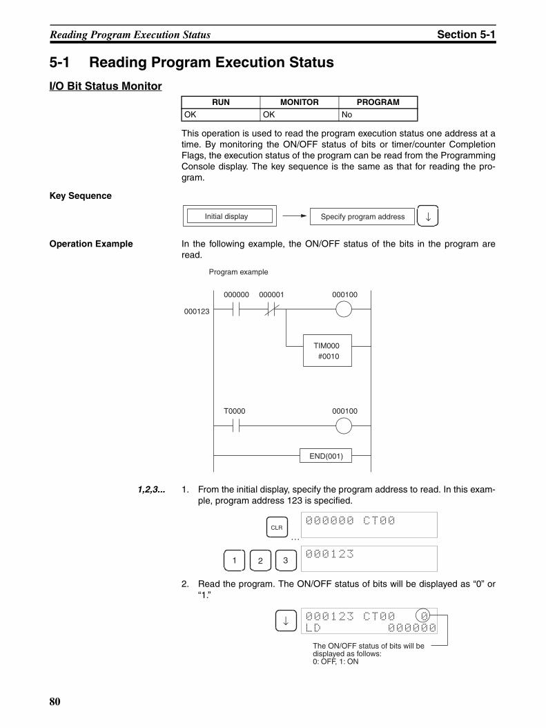
Reading Program Execution Status Section 5-1
5-1 Reading Program Execution Status
I/O Bit Status Monitor
This operation is used to read the program execution status one address at atime. By monitoring the ON/OFF status of bits or timer/counter CompletionFlags, the execution status of the program can be read from the ProgrammingConsole display. The key sequence is the same as that for reading the pro-gram.
Key Sequence
Operation Example In the following example, the ON/OFF status of the bits in the program areread.
1,2,3... 1. From the initial display, specify the program address to read. In this exam-ple, program address 123 is specified.
…
2. Read the program. The ON/OFF status of bits will be displayed as “0” or“1.”
RUN MONITOR PROGRAM
OK OK No
Specify program addressInitial display ↓
Program example
000000 000001
T0000
000123
000100
TIM000#0010
END(001)
000100
CLR000000 CT00
1 2 3000123
↓ 000123 CT00 0
LD 000000
The ON/OFF status of bits will be displayed as follows:0: OFF, 1: ON
80
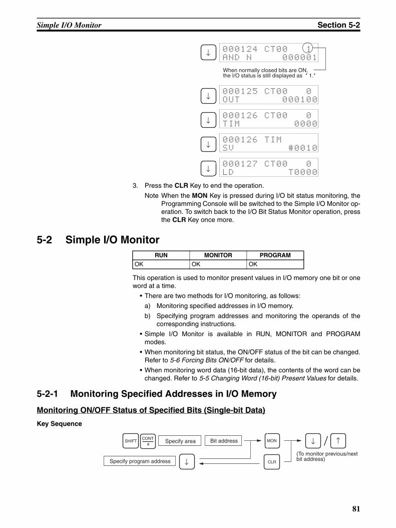
Simple I/O Monitor Section 5-2
3. Press the CLR Key to end the operation.
Note When the MON Key is pressed during I/O bit status monitoring, theProgramming Console will be switched to the Simple I/O Monitor op-eration. To switch back to the I/O Bit Status Monitor operation, pressthe CLR Key once more.
5-2 Simple I/O Monitor
This operation is used to monitor present values in I/O memory one bit or oneword at a time.
• There are two methods for I/O monitoring, as follows:
a) Monitoring specified addresses in I/O memory.
b) Specifying program addresses and monitoring the operands of thecorresponding instructions.
• Simple I/O Monitor is available in RUN, MONITOR and PROGRAMmodes.
• When monitoring bit status, the ON/OFF status of the bit can be changed.Refer to 5-6 Forcing Bits ON/OFF for details.
• When monitoring word data (16-bit data), the contents of the word can bechanged. Refer to 5-5 Changing Word (16-bit) Present Values for details.
5-2-1 Monitoring Specified Addresses in I/O Memory
Monitoring ON/OFF Status of Specified Bits (Single-bit Data)
Key Sequence
↓ 000124 CT00 1
AND N 000001
When normally closed bits are ON, the I/O status is still displayed as " 1."
↓000125 CT00 0
OUT 000100
↓000126 CT00 0
TIM 0000
↓000126 TIM
SV #0010
↓000127 CT00 0
LD T0000
RUN MONITOR PROGRAM
OK OK OK
Specify area Bit addressSHIFT MON
CLRSpecify program address(To monitor previous/next bit address)
CONT#
↓
↑↓
81

Simple I/O Monitor Section 5-2
Operation Example In the following example, auxiliary bit (AR) A40109 is monitored.
1,2,3... 1. From the initial display, input the bit address to be monitored. In this exam-ple, input A40109.
…
2. Start monitoring.
• Press the Up and Down Keys to monitor either the previous or the nextbit.
• Bit ON/OFF status can be changed from this display.
3. Press the CLR Key to exit Simple I/O Monitor.
Designating Bit Address for Monitoring
CLR000000 CT00
SHIFT CONT
#SHIFT
ARHR 4 0 1 0 9
000000
BIT A40109
MON A40109 ^ ON
PV (Bit display)
Type Key sequence Display example
CIO bits
Work bits (WR)
Holding bits (HR)
Auxiliary bits (AR)
SHIFT NumberCONT#
000000
BIT 000015
Bit 15 of CIO 0000
NumberSHIFTCONT
# WR/LR*EM
000000
BIT W00015
Bit 15 of W000
SHIFTARHR
NumberCONT
#000000
BIT H00015
Bit 15 of H000
SHIFTARHR
SHIFT NumberCONT
#000000
BIT A00015
Bit 15 of A000
82
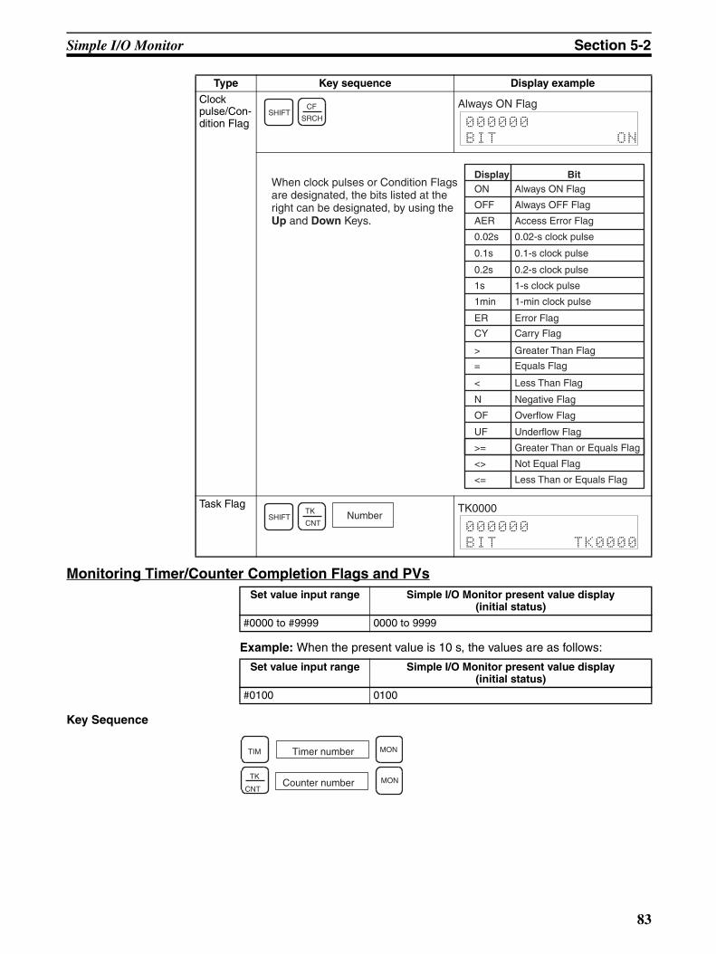
Simple I/O Monitor Section 5-2
Monitoring Timer/Counter Completion Flags and PVs
Example: When the present value is 10 s, the values are as follows:
Key Sequence
Clock pulse/Con-dition Flag
Task Flag
Set value input range Simple I/O Monitor present value display (initial status)
#0000 to #9999 0000 to 9999
Type Key sequence Display example
SHIFTSRCH
CF
000000
BIT ON
Always ON Flag
When clock pulses or Condition Flags are designated, the bits listed at the right can be designated, by using the Up and Down Keys.
ON Always ON Flag
OFF Always OFF Flag
AER Access Error Flag
0.02s 0.02-s clock pulse
0.1s 0.1-s clock pulse
0.2s 0.2-s clock pulse
1s 1-s clock pulse
1min 1-min clock pulse
ER Error Flag
CY Carry Flag
> Greater Than Flag
= Equals Flag
< Less Than Flag
N Negative Flag
OF Overflow Flag
UF Underflow Flag
>= Greater Than or Equals Flag
<> Not Equal Flag
<= Less Than or Equals Flag
Display Bit
SHIFTCNT
TK Number000000
BIT TK0000
TK0000
Set value input range Simple I/O Monitor present value display (initial status)
#0100 0100
TIM MON
TK
CNT
Timer number
Counter number MON
83
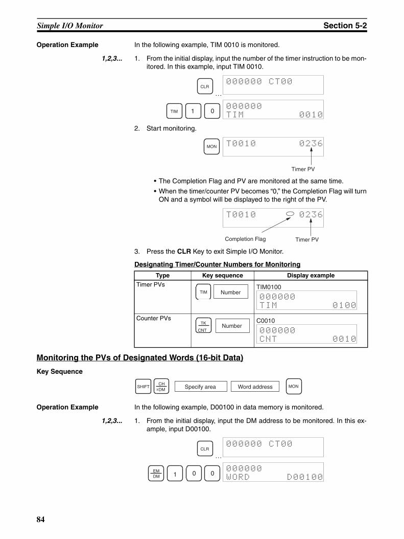
Simple I/O Monitor Section 5-2
Operation Example In the following example, TIM 0010 is monitored.
1,2,3... 1. From the initial display, input the number of the timer instruction to be mon-itored. In this example, input TIM 0010.
…
2. Start monitoring.
• The Completion Flag and PV are monitored at the same time.
• When the timer/counter PV becomes “0,” the Completion Flag will turnON and a symbol will be displayed to the right of the PV.
3. Press the CLR Key to exit Simple I/O Monitor.
Designating Timer/Counter Numbers for Monitoring
Monitoring the PVs of Designated Words (16-bit Data)
Key Sequence
Operation Example In the following example, D00100 in data memory is monitored.
1,2,3... 1. From the initial display, input the DM address to be monitored. In this ex-ample, input D00100.
…
Type Key sequence Display example
Timer PVs
Counter PVs
CLR000000 CT00
TIM 1 0000000
TIM 0010
MON T0010 0236
Timer PV
T0010 0236
Timer PVCompletion Flag
TIM Number000000
TIM 0100
TIM0100
TK
CNTNumber
000000
CNT 0010
C0010
MONWord addressSpecify areaCH
SHIFT*DM
CLR000000 CT00
EMDM 1 0 0
000000
WORD D00100
84
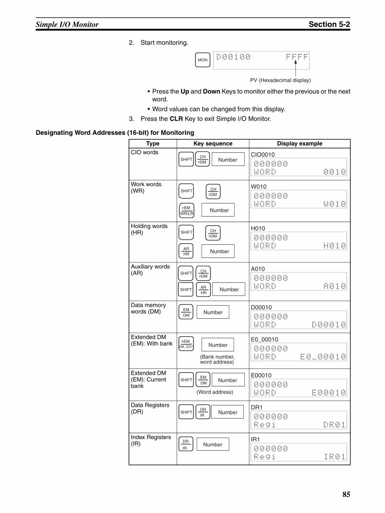
Simple I/O Monitor Section 5-2
2. Start monitoring.
• Press the Up and Down Keys to monitor either the previous or the nextword.
• Word values can be changed from this display.
3. Press the CLR Key to exit Simple I/O Monitor.
Designating Word Addresses (16-bit) for Monitoring
MON D00100 FFFF
PV (Hexadecimal display)
Type Key sequence Display example
CIO words
Work words (WR)
Holding words (HR)
Auxiliary words (AR)
Data memory words (DM)
Extended DM (EM): With bank
Extended DM (EM): Current bank
Data Registers (DR)
Index Registers (IR)
SHIFTCH
Number*DM000000
WORD 0010
CIO0010
Number
SHIFT CH*DM
WR/LR*EM
000000
WORD W010
W010
ARHR Number
SHIFT CH*DM 000000
WORD H010
H010
SHIFT ARHR
Number
SHIFT CH*DM
000000
WORD A010
A010
EMDM
Number000000
WORD D00010
D00010
(Bank number, word address)
NumberEM_/EXT
*EM_
000000
WORD E0_00010
E0_00010
SHIFT
(Word address)
EMDM Number
000000
WORD E00010
E00010
SHIFTDRIR
Number000000
Regi DR01
DR1
DR
IRNumber
000000
Regi IR01
IR1
85
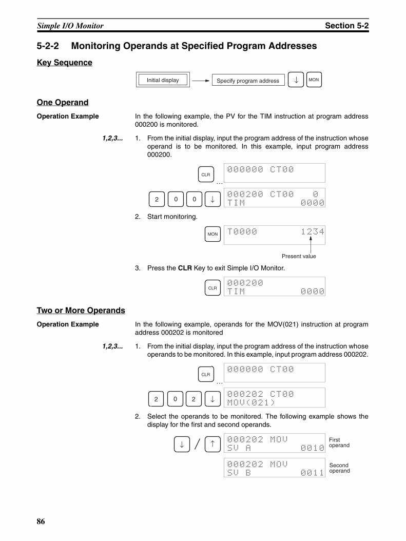
Simple I/O Monitor Section 5-2
5-2-2 Monitoring Operands at Specified Program Addresses
Key Sequence
One Operand
Operation Example In the following example, the PV for the TIM instruction at program address000200 is monitored.
1,2,3... 1. From the initial display, input the program address of the instruction whoseoperand is to be monitored. In this example, input program address000200.
…
2. Start monitoring.
3. Press the CLR Key to exit Simple I/O Monitor.
Two or More Operands
Operation Example In the following example, operands for the MOV(021) instruction at programaddress 000202 is monitored
1,2,3... 1. From the initial display, input the program address of the instruction whoseoperands to be monitored. In this example, input program address 000202.
…
2. Select the operands to be monitored. The following example shows thedisplay for the first and second operands.
MONSpecify program addressInitial display ↓
CLR000000 CT00
2 0 0 ↓000200 CT00 0
TIM 0000
MON T0000 1234
Present value
CLR000200
TIM 0000
CLR000000 CT00
2 0 2 ↓000202 CT00
MOV(021)
↓ ↑000202 MOV
SV A 0010
First operand
000202 MOV
SV B 0011
Second operand
86

I/O Multipoint Monitor Section 5-3
3. Start monitoring.
4. Press the CLR Key to exit Simple I/O Monitor.
5-3 I/O Multipoint Monitor
This operation is used to monitor up to four bits or words simultaneously.
• Four bits and/or words can be monitored at the same time, but only 2 ofthese can be displayed simultaneously.
Key Sequence
Operation Example In the following example, T0001, CIO 000001, D00000, and CIO 1225 aremonitored.
1,2,3... 1. Specify the bits and words for monitoring, in succession as shown in thefollowing steps. The status/present values of the specified bits and wordswill appear at the top of the display. Methods for specifying bits or wordsare the same as for Simple I/O Monitor.
…a) Specify T0001 and the present value will appear at the top of the dis-
play.
b) Specify CIO bit 000001 and the status will appear at the top of the dis-play.
MON 0011 1234
Present value
CLR000202
WORD 0011
RUN MONITOR PROGRAM
OK OK OK
Simple I/O MonitorSimple I/O Monitor
CLR000000 CT00
TIM 1 MON T0001 0100
The present value for T 0001.
SHIFT CONT
# 1 MON 000001 ^ OFF
T0001 0100
The present value for 000001. The present value
for T 0001.
87
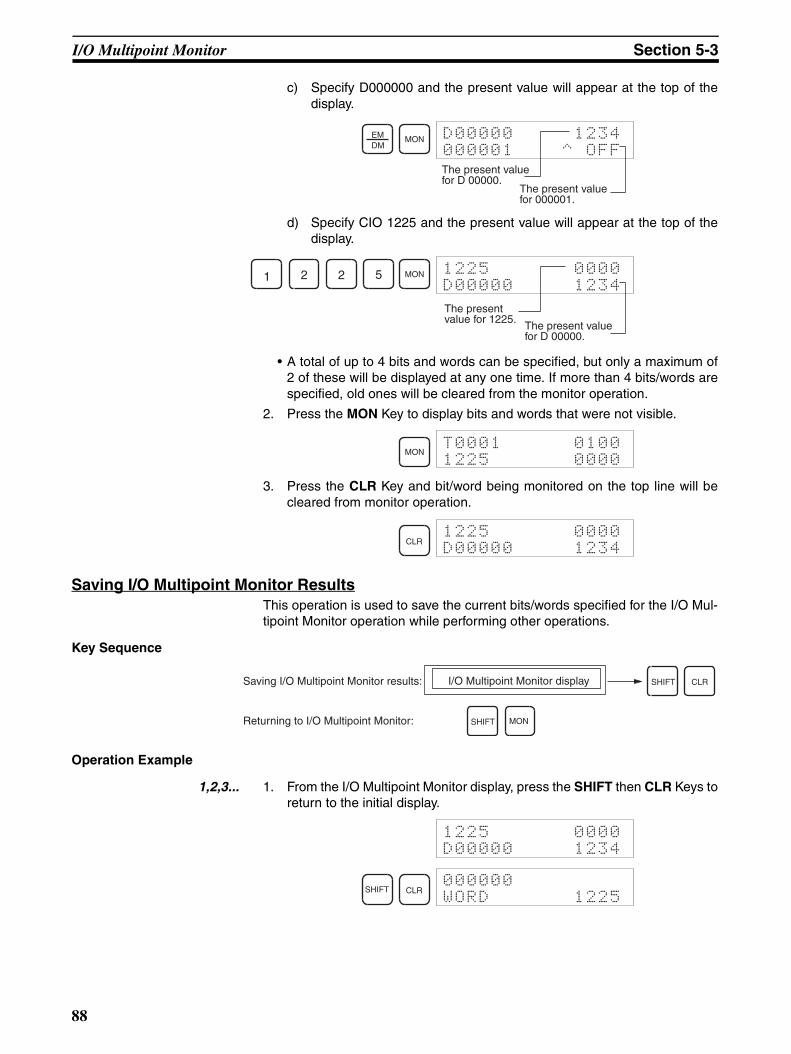
I/O Multipoint Monitor Section 5-3
c) Specify D000000 and the present value will appear at the top of thedisplay.
d) Specify CIO 1225 and the present value will appear at the top of thedisplay.
• A total of up to 4 bits and words can be specified, but only a maximum of2 of these will be displayed at any one time. If more than 4 bits/words arespecified, old ones will be cleared from the monitor operation.
2. Press the MON Key to display bits and words that were not visible.
3. Press the CLR Key and bit/word being monitored on the top line will becleared from monitor operation.
Saving I/O Multipoint Monitor ResultsThis operation is used to save the current bits/words specified for the I/O Mul-tipoint Monitor operation while performing other operations.
Key Sequence
Operation Example
1,2,3... 1. From the I/O Multipoint Monitor display, press the SHIFT then CLR Keys toreturn to the initial display.
EMDM
MON D00000 1234
000001 ^ OFF
The present value for D 00000.
The present value for 000001.
1 2 2 5 MON 1225 0000
D00000 1234
The present value for 1225.
The present value for D 00000.
MONT0001 0100
1225 0000
CLR1225 0000
D00000 1234
Saving I/O Multipoint Monitor results: SHIFT CLR
MONSHIFTReturning to I/O Multipoint Monitor:
I/O Multipoint Monitor display
1225 0000
D00000 1234
SHIFT CLR000000
WORD 1225
88
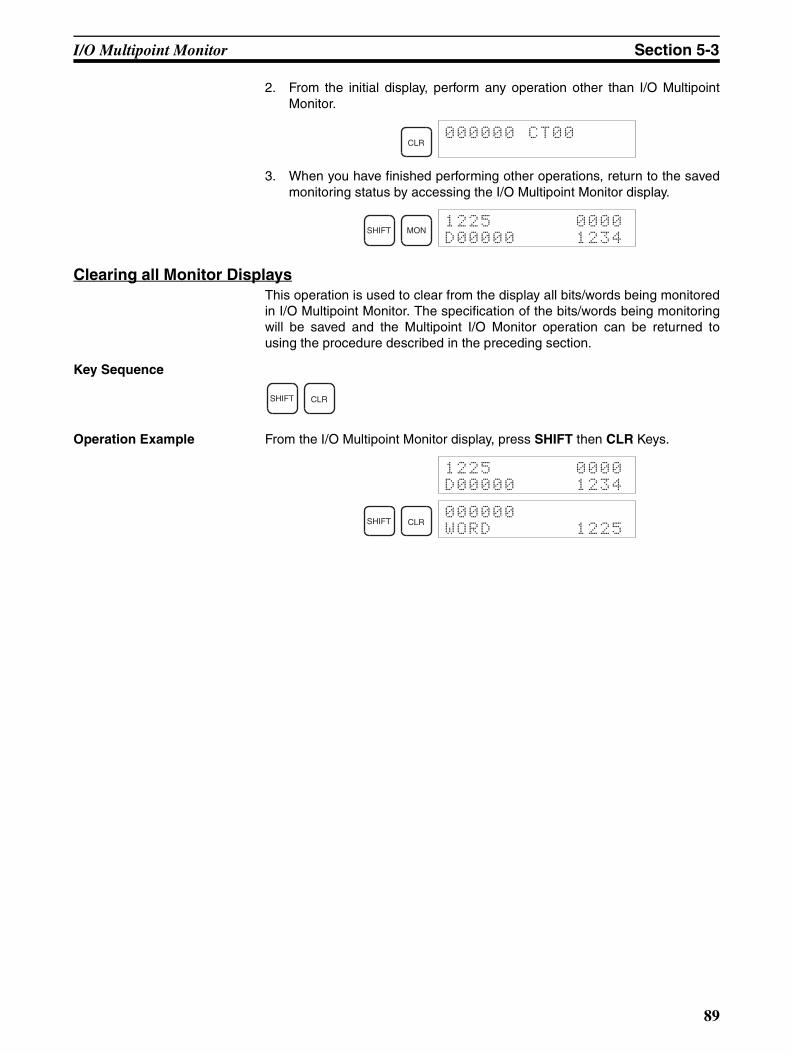
I/O Multipoint Monitor Section 5-3
2. From the initial display, perform any operation other than I/O MultipointMonitor.
3. When you have finished performing other operations, return to the savedmonitoring status by accessing the I/O Multipoint Monitor display.
Clearing all Monitor DisplaysThis operation is used to clear from the display all bits/words being monitoredin I/O Multipoint Monitor. The specification of the bits/words being monitoringwill be saved and the Multipoint I/O Monitor operation can be returned tousing the procedure described in the preceding section.
Key Sequence
Operation Example From the I/O Multipoint Monitor display, press SHIFT then CLR Keys.
CLR000000 CT00
SHIFT MON1225 0000
D00000 1234
SHIFT CLR
1225 0000
D00000 1234
SHIFT CLR000000
WORD 1225
89

Monitor Display Format Section 5-4
5-4 Monitor Display FormatThe display format for words (16-bit data) in Simple I/O Monitor or I/O Multi-point Monitor can be changed to display formats other then binary (i.e., 4-digitand 2-digit hexadecimal), such as signed decimal, unsigned decimal, andASCII. The word (16-bit data) display format can be changed using the follow-ing key combinations.
Simple I/O Monitor
Hexadecimal or 4-digit BCD
(Simple I/O Monitor displays are shown.)
D00200 B141
16-digit BCD
D00200 MON
1011000101000001
SHIFT MON
CLR
,–IR
TRData display change
Unsigned decimal
D00200 -20159
Unsigned double-word decimal
D00201 D00200
+45377
,IR+
,IR
CLR
Signed decimal
D00200 &45377
Signed double-word decimal
D00201 D00200
&45377
CLR
ASCII
D00200 "1A"
CLR
CLR
CLR
I/O Multipoint Monitor
NOTC
,–IR
TR
,–IR
TR
,–IR
TR
,–IR
TR
,IR+
,IR
90
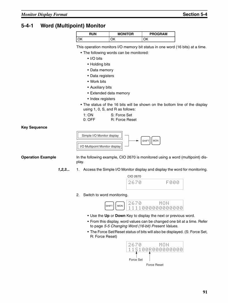
Monitor Display Format Section 5-4
5-4-1 Word (Multipoint) Monitor
This operation monitors I/O memory bit status in one word (16 bits) at a time.
• The following words can be monitored:
• I/O bits
• Holding bits
• Data memory
• Data registers
• Work bits
• Auxiliary bits
• Extended data memory
• Index registers
• The status of the 16 bits will be shown on the bottom line of the displayusing 1, 0, S, and R as follows:
1: ON S: Force Set0: OFF R: Force Reset
Key Sequence
Operation Example In the following example, CIO 2670 is monitored using a word (multipoint) dis-play.
1,2,3... 1. Access the Simple I/O Monitor display and display the word for monitoring.
2. Switch to word monitoring.
• Use the Up or Down Key to display the next or previous word.
• From this display, word values can be changed one bit at a time. Referto page 5-5 Changing Word (16-bit) Present Values.
• The Force Set/Reset status of bits will also be displayed. (S: Force Set,R: Force Reset)
RUN MONITOR PROGRAM
OK OK OK
Simple I/O Monitor display
MONSHIFT
I/O Multipoint Monitor display
2670 F000
CIO 2670
SHIFT MON2670 MON
1111000000000000
2670 MON
11S100R000000000
Force Set
Force Reset
91
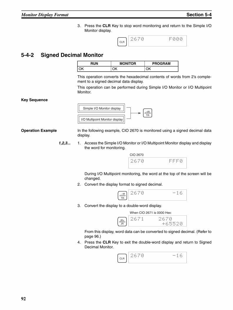
Monitor Display Format Section 5-4
3. Press the CLR Key to stop word monitoring and return to the Simple I/OMonitor display.
5-4-2 Signed Decimal Monitor
This operation converts the hexadecimal contents of words from 2’s comple-ment to a signed decimal data display.
This operation can be performed during Simple I/O Monitor or I/O MultipointMonitor.
Key Sequence
Operation Example In the following example, CIO 2670 is monitored using a signed decimal datadisplay.
1,2,3... 1. Access the Simple I/O Monitor or I/O Multipoint Monitor display and displaythe word for monitoring.
During I/O Multipoint monitoring, the word at the top of the screen will bechanged.
2. Convert the display format to signed decimal.
3. Convert the display to a double-word display.
From this display, word data can be converted to signed decimal. (Refer topage 96.)
4. Press the CLR Key to exit the double-word display and return to SignedDecimal Monitor.
CLR2670 F000
RUN MONITOR PROGRAM
OK OK OK
,–IR
TR
Simple I/O Monitor display
I/O Multipoint Monitor display
2670 FFF0
CIO 2670
,–IR
TR
2670 -16
,IR+,IR
2671 2670
+65520
When CIO 2671 is 0000 Hex:
CLR2670 -16
92
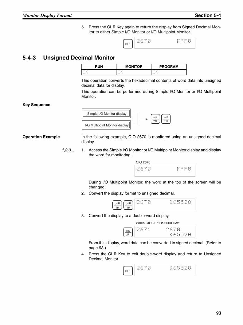
Monitor Display Format Section 5-4
5. Press the CLR Key again to return the display from Signed Decimal Mon-itor to either Simple I/O Monitor or I/O Multipoint Monitor.
5-4-3 Unsigned Decimal Monitor
This operation converts the hexadecimal contents of word data into unsigneddecimal data for display.
This operation can be performed during Simple I/O Monitor or I/O MultipointMonitor.
Key Sequence
Operation Example In the following example, CIO 2670 is monitored using an unsigned decimaldisplay.
1,2,3... 1. Access the Simple I/O Monitor or I/O Multipoint Monitor display and displaythe word for monitoring.
During I/O Multipoint Monitor, the word at the top of the screen will bechanged.
2. Convert the display format to unsigned decimal.
3. Convert the display to a double-word display.
From this display, word data can be converted to signed decimal. (Refer topage 98.)
4. Press the CLR Key to exit double-word display and return to UnsignedDecimal Monitor.
CLR2670 FFF0
RUN MONITOR PROGRAM
OK OK OK
,–IRTR
Simple I/O Monitor display
I/O Multipoint Monitor display
,–IRTR
2670 FFF0
CIO 2670
,–IR
TR
,–IR
TR
2670 &65520
,IR+,IR
2671 2670
&65520
When CIO 2671 is 0000 Hex:
CLR2670 &65520
93
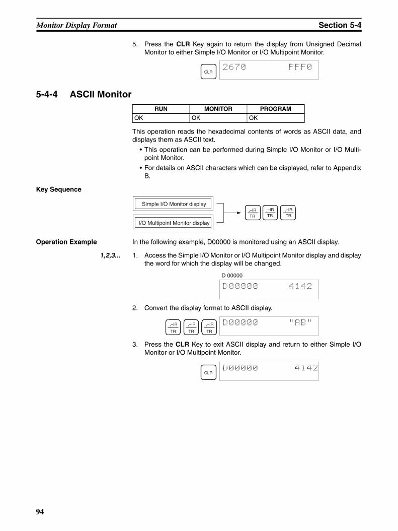
Monitor Display Format Section 5-4
5. Press the CLR Key again to return the display from Unsigned DecimalMonitor to either Simple I/O Monitor or I/O Multipoint Monitor.
5-4-4 ASCII Monitor
This operation reads the hexadecimal contents of words as ASCII data, anddisplays them as ASCII text.
• This operation can be performed during Simple I/O Monitor or I/O Multi-point Monitor.
• For details on ASCII characters which can be displayed, refer to AppendixB.
Key Sequence
Operation Example In the following example, D00000 is monitored using an ASCII display.
1,2,3... 1. Access the Simple I/O Monitor or I/O Multipoint Monitor display and displaythe word for which the display will be changed.
2. Convert the display format to ASCII display.
3. Press the CLR Key to exit ASCII display and return to either Simple I/OMonitor or I/O Multipoint Monitor.
CLR2670 FFF0
RUN MONITOR PROGRAM
OK OK OK
Simple I/O Monitor display
I/O Multipoint Monitor display
,–IRTR
,–IRTR
,–IRTR
D00000 4142
D 00000
,–IR
TR
,–IR
TR
,–IR
TR
D00000 "AB"
CLRD00000 4142
94
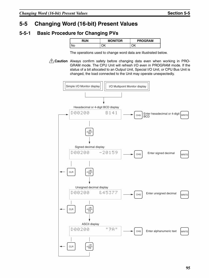
Changing Word (16-bit) Present Values Section 5-5
5-5 Changing Word (16-bit) Present Values
5-5-1 Basic Procedure for Changing PVs
The operations used to change word data are illustrated below.
!Caution Always confirm safety before changing data even when working in PRO-GRAM mode. The CPU Unit will refresh I/O even in PROGRAM mode. If thestatus of a bit allocated to an Output Unit, Special I/O Unit, or CPU Bus Unit ischanged, the load connected to the Unit may operate unexpectedly.
RUN MONITOR PROGRAM
No OK OK
Simple I/O Monitor display
Hexadecimal or 4-digit BCD display
D00200 B141
Signed decimal display
D00200 -20159
CLR
Unsigned decimal display
D00200 &45377
CLR
ASCII display
D00200 "1A"
CLR
Enter hexadecimal or 4-digit BCD
Enter signed decimal
Enter unsigned decimal
Enter alphanumeric text
WRITE
WRITE
WRITE
WRITE
I/O Multipoint Monitor display
CHG
CHG
CHG
CHG
,–IRTR
,–IRTR
,–IRTR
,–IRTR
95
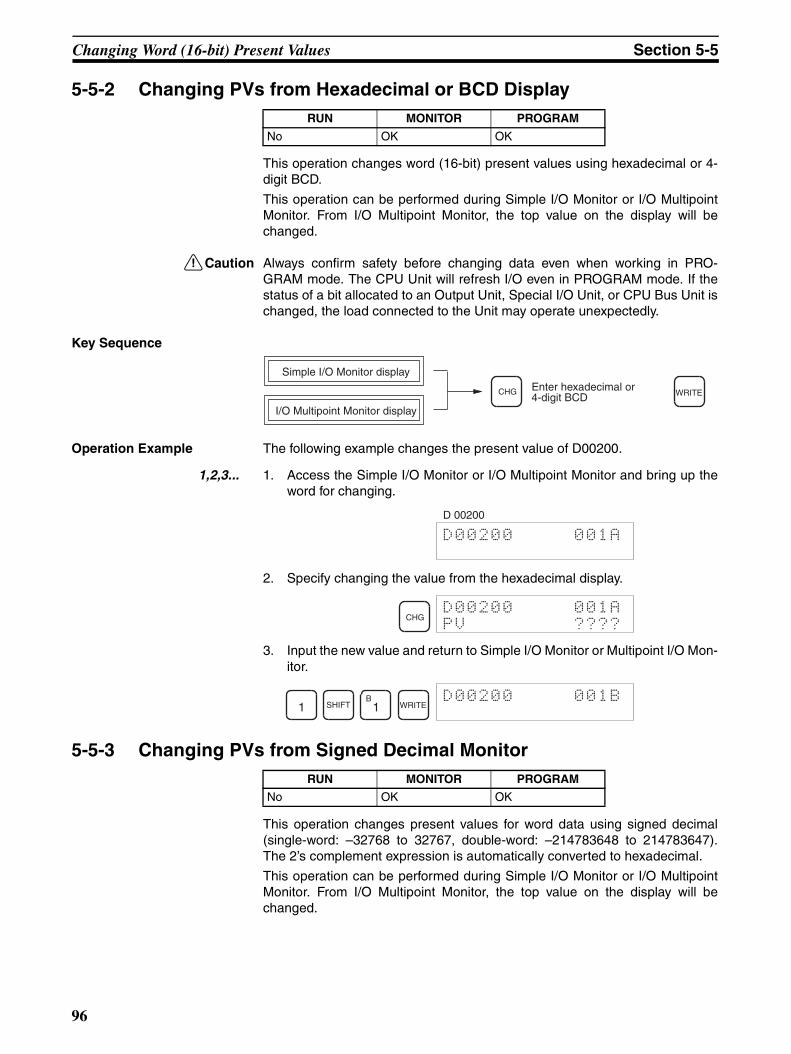
Changing Word (16-bit) Present Values Section 5-5
5-5-2 Changing PVs from Hexadecimal or BCD Display
This operation changes word (16-bit) present values using hexadecimal or 4-digit BCD.
This operation can be performed during Simple I/O Monitor or I/O MultipointMonitor. From I/O Multipoint Monitor, the top value on the display will bechanged.
!Caution Always confirm safety before changing data even when working in PRO-GRAM mode. The CPU Unit will refresh I/O even in PROGRAM mode. If thestatus of a bit allocated to an Output Unit, Special I/O Unit, or CPU Bus Unit ischanged, the load connected to the Unit may operate unexpectedly.
Key Sequence
Operation Example The following example changes the present value of D00200.
1,2,3... 1. Access the Simple I/O Monitor or I/O Multipoint Monitor and bring up theword for changing.
2. Specify changing the value from the hexadecimal display.
3. Input the new value and return to Simple I/O Monitor or Multipoint I/O Mon-itor.
5-5-3 Changing PVs from Signed Decimal Monitor
This operation changes present values for word data using signed decimal(single-word: –32768 to 32767, double-word: –214783648 to 214783647).The 2’s complement expression is automatically converted to hexadecimal.
This operation can be performed during Simple I/O Monitor or I/O MultipointMonitor. From I/O Multipoint Monitor, the top value on the display will bechanged.
RUN MONITOR PROGRAM
No OK OK
CHG WRITEEnter hexadecimal or 4-digit BCD
Simple I/O Monitor display
I/O Multipoint Monitor display
D00200 001A
D 00200
CHGD00200 001A
PV ????
1 SHIFTB1 WRITE
D00200 001B
RUN MONITOR PROGRAM
No OK OK
96
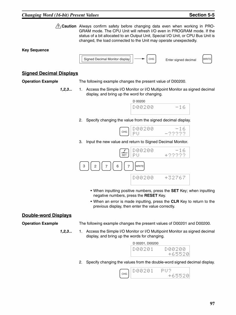
Changing Word (16-bit) Present Values Section 5-5
!Caution Always confirm safety before changing data even when working in PRO-GRAM mode. The CPU Unit will refresh I/O even in PROGRAM mode. If thestatus of a bit allocated to an Output Unit, Special I/O Unit, or CPU Bus Unit ischanged, the load connected to the Unit may operate unexpectedly.
Key Sequence
Signed Decimal Displays
Operation Example The following example changes the present value of D00200.
1,2,3... 1. Access the Simple I/O Monitor or I/O Multipoint Monitor as signed decimaldisplay, and bring up the word for changing.
2. Specify changing the value from the signed decimal display.
3. Input the new value and return to Signed Decimal Monitor.
• When inputting positive numbers, press the SET Key; when inputtingnegative numbers, press the RESET Key.
• When an error is made inputting, press the CLR Key to return to theprevious display, then enter the value correctly.
Double-word Displays
Operation Example The following example changes the present values of D00201 and D00200.
1,2,3... 1. Access the Simple I/O Monitor or I/O Multipoint Monitor as signed decimaldisplay, and bring up the words for changing.
2. Specify changing the values from the double-word signed decimal display.
Signed Decimal Monitor display CHG WRITEEnter signed decimal
D00200 -16
D 00200
CHGD00200 -16
PV -?????
SET
D00200 -16
PV +?????
3 2 7 6 7 WRITE
D00200 +32767
D00201 D00200
+65520
D 00201, D00200
CHGD00201 PV?
+65520
97
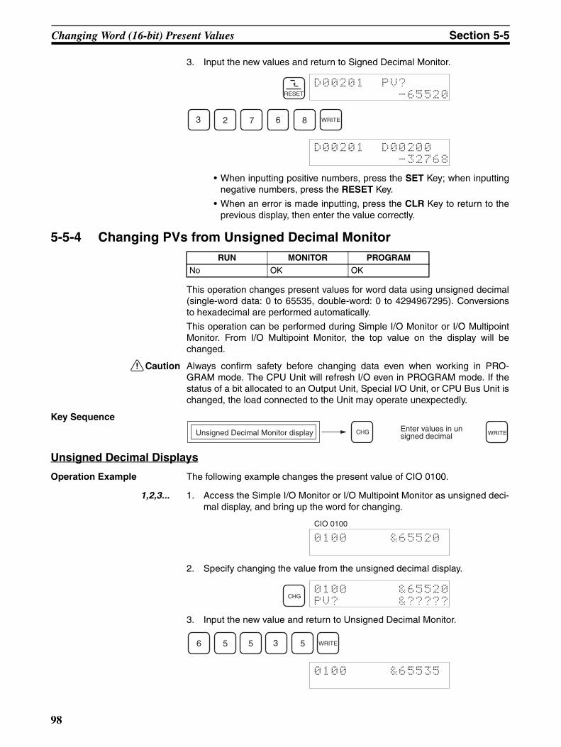
Changing Word (16-bit) Present Values Section 5-5
3. Input the new values and return to Signed Decimal Monitor.
• When inputting positive numbers, press the SET Key; when inputtingnegative numbers, press the RESET Key.
• When an error is made inputting, press the CLR Key to return to theprevious display, then enter the value correctly.
5-5-4 Changing PVs from Unsigned Decimal Monitor
This operation changes present values for word data using unsigned decimal(single-word data: 0 to 65535, double-word: 0 to 4294967295). Conversionsto hexadecimal are performed automatically.
This operation can be performed during Simple I/O Monitor or I/O MultipointMonitor. From I/O Multipoint Monitor, the top value on the display will bechanged.
!Caution Always confirm safety before changing data even when working in PRO-GRAM mode. The CPU Unit will refresh I/O even in PROGRAM mode. If thestatus of a bit allocated to an Output Unit, Special I/O Unit, or CPU Bus Unit ischanged, the load connected to the Unit may operate unexpectedly.
Key Sequence
Unsigned Decimal Displays
Operation Example The following example changes the present value of CIO 0100.
1,2,3... 1. Access the Simple I/O Monitor or I/O Multipoint Monitor as unsigned deci-mal display, and bring up the word for changing.
2. Specify changing the value from the unsigned decimal display.
3. Input the new value and return to Unsigned Decimal Monitor.
RESET
D00201 PV?
-65520
3 2 7 6 8 WRITE
D00201 D00200
-32768
RUN MONITOR PROGRAM
No OK OK
Unsigned Decimal Monitor display CHG WRITEEnter values in unsigned decimal
0100 &65520
CIO 0100
CHG0100 &65520
PV? &?????
6 5 5 3 5 WRITE
0100 &65535
98
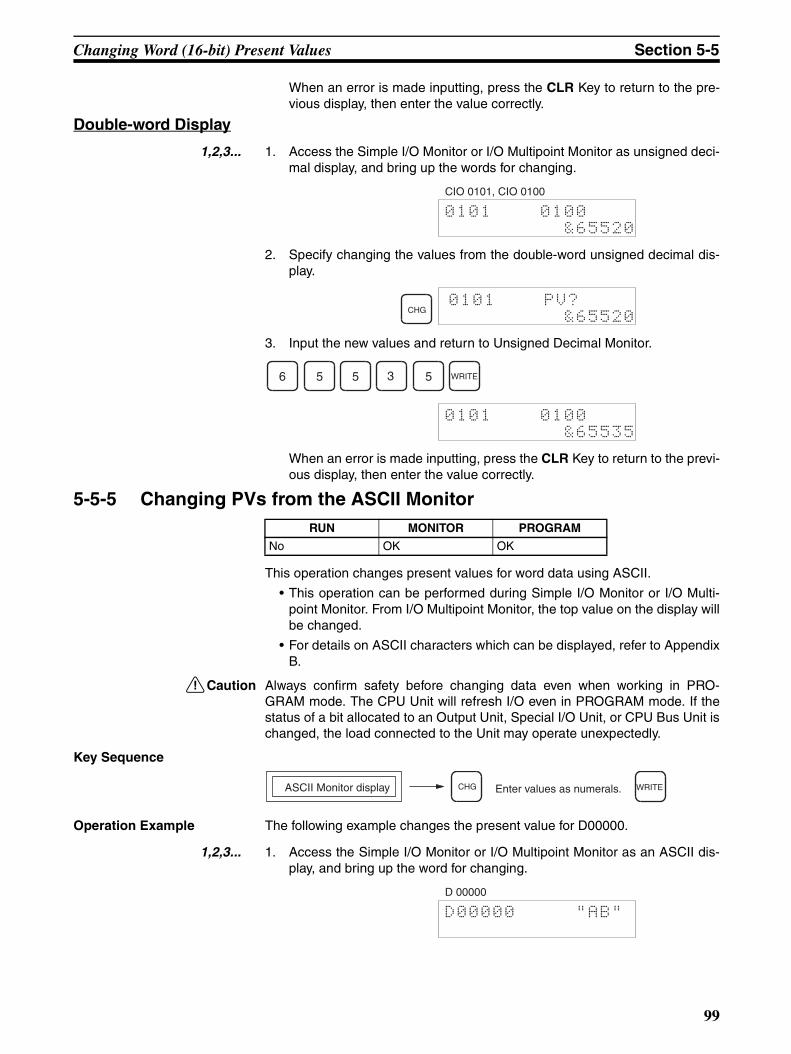
Changing Word (16-bit) Present Values Section 5-5
When an error is made inputting, press the CLR Key to return to the pre-vious display, then enter the value correctly.
Double-word Display
1,2,3... 1. Access the Simple I/O Monitor or I/O Multipoint Monitor as unsigned deci-mal display, and bring up the words for changing.
2. Specify changing the values from the double-word unsigned decimal dis-play.
3. Input the new values and return to Unsigned Decimal Monitor.
When an error is made inputting, press the CLR Key to return to the previ-ous display, then enter the value correctly.
5-5-5 Changing PVs from the ASCII Monitor
This operation changes present values for word data using ASCII.
• This operation can be performed during Simple I/O Monitor or I/O Multi-point Monitor. From I/O Multipoint Monitor, the top value on the display willbe changed.
• For details on ASCII characters which can be displayed, refer to AppendixB.
!Caution Always confirm safety before changing data even when working in PRO-GRAM mode. The CPU Unit will refresh I/O even in PROGRAM mode. If thestatus of a bit allocated to an Output Unit, Special I/O Unit, or CPU Bus Unit ischanged, the load connected to the Unit may operate unexpectedly.
Key Sequence
Operation Example The following example changes the present value for D00000.
1,2,3... 1. Access the Simple I/O Monitor or I/O Multipoint Monitor as an ASCII dis-play, and bring up the word for changing.
0101 0100
&65520
CIO 0101, CIO 0100
CHG0101 PV?
&65520
6 5 5 3 5 WRITE
0101 0100
&65535
RUN MONITOR PROGRAM
No OK OK
ASCII Monitor display CHG WRITEEnter values as numerals.
D00000 "AB"
D 00000
99
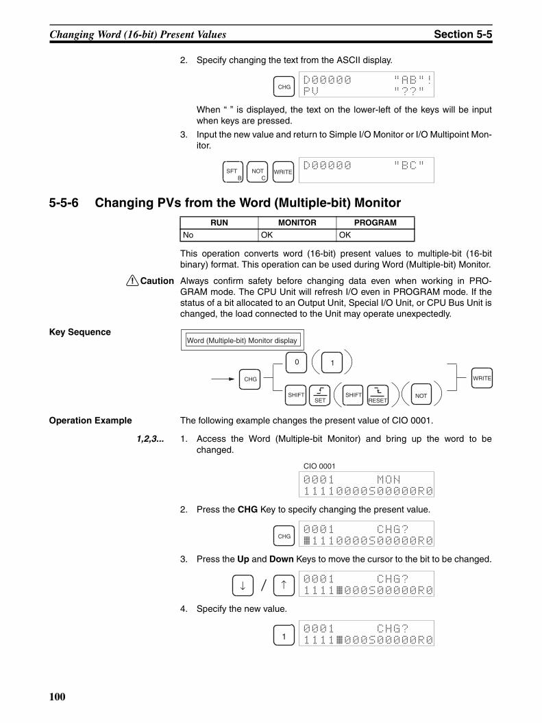
Changing Word (16-bit) Present Values Section 5-5
2. Specify changing the text from the ASCII display.
When “ ” is displayed, the text on the lower-left of the keys will be inputwhen keys are pressed.
3. Input the new value and return to Simple I/O Monitor or I/O Multipoint Mon-itor.
5-5-6 Changing PVs from the Word (Multiple-bit) Monitor
This operation converts word (16-bit) present values to multiple-bit (16-bitbinary) format. This operation can be used during Word (Multiple-bit) Monitor.
!Caution Always confirm safety before changing data even when working in PRO-GRAM mode. The CPU Unit will refresh I/O even in PROGRAM mode. If thestatus of a bit allocated to an Output Unit, Special I/O Unit, or CPU Bus Unit ischanged, the load connected to the Unit may operate unexpectedly.
Key Sequence
Operation Example The following example changes the present value of CIO 0001.
1,2,3... 1. Access the Word (Multiple-bit Monitor) and bring up the word to bechanged.
2. Press the CHG Key to specify changing the present value.
3. Press the Up and Down Keys to move the cursor to the bit to be changed.
4. Specify the new value.
CHGD00000 "AB"!
PV "??"
SFTB
NOTC
WRITED00000 "BC"
RUN MONITOR PROGRAM
No OK OK
Word (Multiple-bit) Monitor display
CHG WRITE
0 1
SHIFT SHIFT NOTSET RESET
0001 MON
11110000S00000R0
CIO 0001
CHG0001 CHG?
~1110000S00000R0
↓ ↑0001 CHG?
1111~000S00000R0
10001 CHG?
1111~000S00000R0
100

Forcing Bits ON/OFF Section 5-6
The cursor position after inputting a new value varies depending on the lastkey pressed for moving the cursor.Press the Up and Down Keys to confirm the new value.
Press the Down Key Press the Up Key
The procedure for inputting the new value is as follows:
: OFF
: ON
: Force Set (S) (Not possible in data memory)
: Force Reset (R) (Not possible in data memory)
: Clear Force Set/Reset
5. Input the new values and return to the Word Monitor.
5-6 Forcing Bits ON/OFF
This operation is used to force bits ON/OFF regardless of any external inputsor results of user program execution. This operation can be performed duringSimple I/O Monitor or I/O Multipoint Monitor.
!Caution Always confirm safety before setting or resetting bits even when working inPROGRAM mode. The CPU Unit will refresh I/O even in PROGRAM mode. Ifthe status of a bit allocated to an Output Unit, Special I/O Unit, or CPU BusUnit is changed, the load connected to the Unit may operate unexpectedly.
5-6-1 Continuous Force Set/ResetKey Sequence
0001 CHG?
11111~00S00000R00001 CHG?
111~1000S00000R0
0
1
SHIFTSET
SHIFTRESET
NOT
WRITE0001 MON
11111000S00000R0
RUN MONITOR PROGRAM
No OK OK
Simple I/O Monitor display
I/O Multipoint Monitor display
Force Set:
Force Reset:
Clear:
SHIFT
SHIFT
NOT
SET
RESET
101

Forcing Bits ON/OFF Section 5-6
Operation Example The following example uses Force Set/Reset to reset bit 00 of CIO 0001.
1,2,3... 1. Access the Simple I/O Monitor or the I/O Multipoint Monitor and bring upthe bit to be Force Set/Reset. The following example shows the I/O Multi-point Monitor.
From the I/O Multipoint Monitor, the bit at the top of the display will bechanged.
2. When a bit has been Force Set, an “S” will appear and when it has beenForce Reset, an “R” will appear on the display. The forced ON/OFF statusof the bit will not be affected by external input changes or the result of ex-ecuting a command.
Key sequence:
: Continuous Force Set.
: Continuous Force Reset.
: Continuous Force Set/Reset clear.
Continuous Force Set/Reset can be cleared by pressing the NOT Key toperform the Clear Force Set/Reset operation. Force Set/Reset is clearedwhen the following operations are performed:
a) When the Clear Force Set/Reset operation is executed.
b) When the operating mode of the PLC is changed. If the Forced StatusHold Bit is ON, however, Force Set/Reset bits will not be cleared whenthe PLC mode is changed from PROGRAM to MONITOR.
c) When operation stops as the result of a fatal error.
d) When operation stops as a result of power interruption.
5-6-2 Temporary Force Set/Reset This operation force-sets/resets a bit only while the key is held down.
Key Sequence
000100 ^ OFF
000001 ^ ON
Bit 00 of CIO 0001
SHIFTSET
000100 S ON
000001 ^ ON
SHIFTSET
SHIFTRESET
NOT
Simple I/O Monitor display
I/O Multipoint Monitor display
Force Set:
Force Reset:
SET
RESET
102
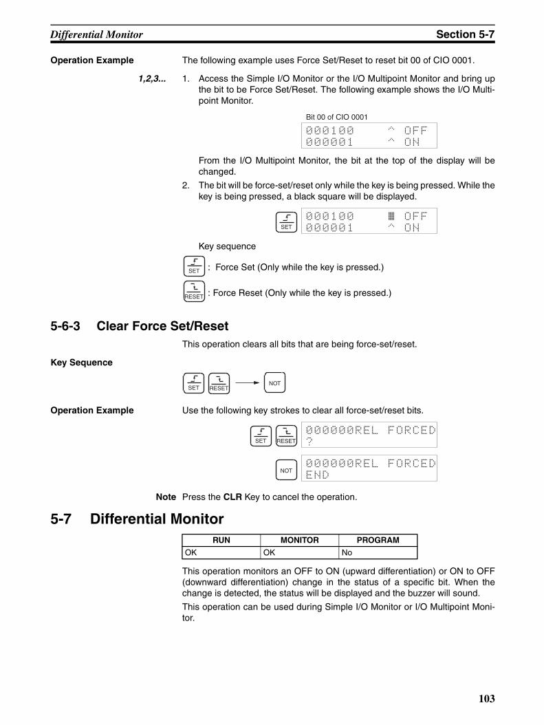
Differential Monitor Section 5-7
Operation Example The following example uses Force Set/Reset to reset bit 00 of CIO 0001.
1,2,3... 1. Access the Simple I/O Monitor or the I/O Multipoint Monitor and bring upthe bit to be Force Set/Reset. The following example shows the I/O Multi-point Monitor.
From the I/O Multipoint Monitor, the bit at the top of the display will bechanged.
2. The bit will be force-set/reset only while the key is being pressed. While thekey is being pressed, a black square will be displayed.
Key sequence
: Force Set (Only while the key is pressed.)
: Force Reset (Only while the key is pressed.)
5-6-3 Clear Force Set/ResetThis operation clears all bits that are being force-set/reset.
Key Sequence
Operation Example Use the following key strokes to clear all force-set/reset bits.
Note Press the CLR Key to cancel the operation.
5-7 Differential Monitor
This operation monitors an OFF to ON (upward differentiation) or ON to OFF(downward differentiation) change in the status of a specific bit. When thechange is detected, the status will be displayed and the buzzer will sound.
This operation can be used during Simple I/O Monitor or I/O Multipoint Moni-tor.
000100 ^ OFF
000001 ^ ON
Bit 00 of CIO 0001
SET
000100 ~ OFF000001 ^ ON
SET
RESET
NOTSET RESET
SET RESET
000000REL FORCED
?
NOT000000REL FORCED
END
RUN MONITOR PROGRAM
OK OK No
103
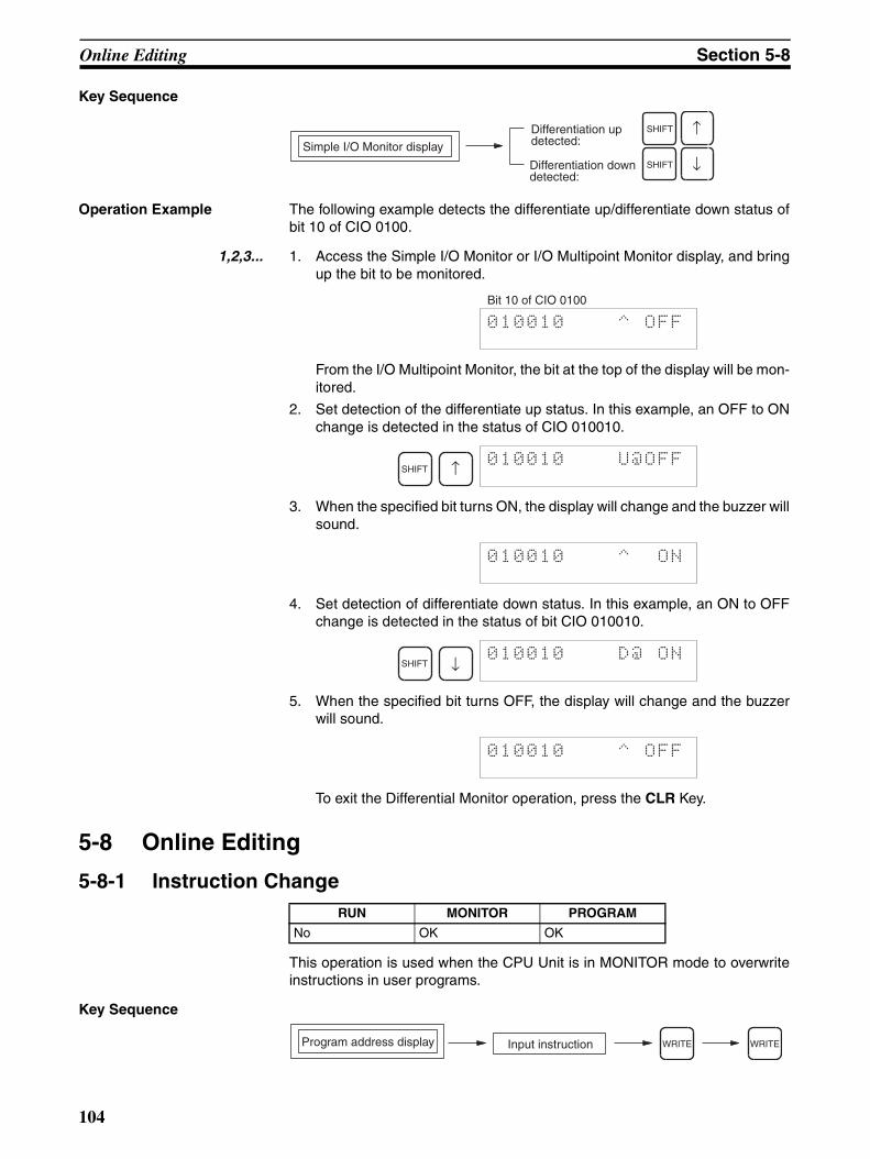
Online Editing Section 5-8
Key Sequence
Operation Example The following example detects the differentiate up/differentiate down status ofbit 10 of CIO 0100.
1,2,3... 1. Access the Simple I/O Monitor or I/O Multipoint Monitor display, and bringup the bit to be monitored.
From the I/O Multipoint Monitor, the bit at the top of the display will be mon-itored.
2. Set detection of the differentiate up status. In this example, an OFF to ONchange is detected in the status of CIO 010010.
3. When the specified bit turns ON, the display will change and the buzzer willsound.
4. Set detection of differentiate down status. In this example, an ON to OFFchange is detected in the status of bit CIO 010010.
5. When the specified bit turns OFF, the display will change and the buzzerwill sound.
To exit the Differential Monitor operation, press the CLR Key.
5-8 Online Editing
5-8-1 Instruction Change
This operation is used when the CPU Unit is in MONITOR mode to overwriteinstructions in user programs.
Key Sequence
Simple I/O Monitor display
Differentiation up detected:
Differentiation down detected:
SHIFT
SHIFT ↓
↑
010010 ^ OFF
Bit 10 of CIO 0100
SHIFT ↑010010 U@OFF
010010 ^ ON
SHIFT ↓010010 D@ ON
010010 ^ OFF
RUN MONITOR PROGRAM
No OK OK
Input instructionProgram address display WRITE WRITE
104

Online Editing Section 5-8
Operation Example In the following instruction block, the instruction at address 00200 will bechanged to LD NOT 000002.
1,2,3... 1. From the initial display, access the program address containing the instruc-tion to be changed.
…
2. Input the new instruction and press the WRITE Key.
3. Press the WRITE Key once more.
After pressing the WRITE Key the second time, the altered program will beexecuted from the next scan.
4. Press the Up Key to check the instruction.
5-8-2 Instruction Add
This operation is used when the CPU Unit is in MONITOR mode to add aninstruction to the end of the user program.
Note Refer to 4-1 Inputting Instructions for details on adding instructions in PRO-GRAM mode.
Key Sequence
Operation Example In the following instruction block, LD 000002 and OUT 000100 are addedbefore the END(001) instruction.
Address Instruction Operand
: : :
000200 LD 000001
000201 AND 000200
: : :
Changed to LD NOT 000002.
CLR000000 CT00
2 0 0 ↓000200 CT00 0
LD 000001
AALD
NOT 2 WRITEONLINE EDIT?
LD N 000002
WRITE000201 CT00 0
AND 000200
↑000200 CT00 1
LD N 000002
RUN MONITOR PROGRAM
No OK See note.
Input instructionProgram address display WRITE WRITE
Address Instruction Operand
: : :
123456 ENDLD 000002 and OUT 000100 are added.
105
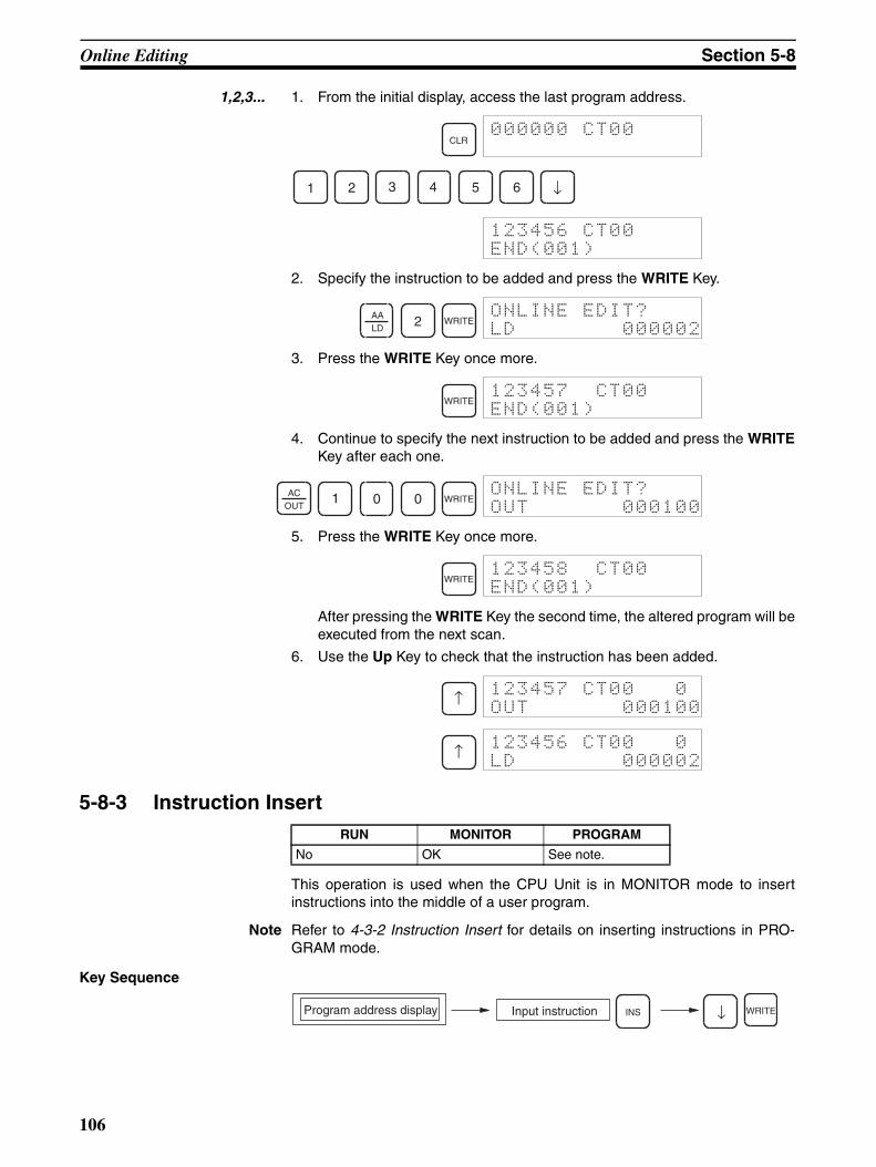
Online Editing Section 5-8
1,2,3... 1. From the initial display, access the last program address.
2. Specify the instruction to be added and press the WRITE Key.
3. Press the WRITE Key once more.
4. Continue to specify the next instruction to be added and press the WRITEKey after each one.
5. Press the WRITE Key once more.
After pressing the WRITE Key the second time, the altered program will beexecuted from the next scan.
6. Use the Up Key to check that the instruction has been added.
5-8-3 Instruction Insert
This operation is used when the CPU Unit is in MONITOR mode to insertinstructions into the middle of a user program.
Note Refer to 4-3-2 Instruction Insert for details on inserting instructions in PRO-GRAM mode.
Key Sequence
CLR000000 CT00
1 2 3 4 5 6 ↓
123456 CT00
END(001)
AALD
2 WRITEONLINE EDIT?
LD 000002
WRITE123457 CT00
END(001)
ACOUT
1 0 0 WRITEONLINE EDIT?
OUT 000100
WRITE123458 CT00
END(001)
↑123457 CT00 0
OUT 000100
↑123456 CT00 0
LD 000002
RUN MONITOR PROGRAM
No OK See note.
Input instructionProgram address display WRITEINS ↓
106
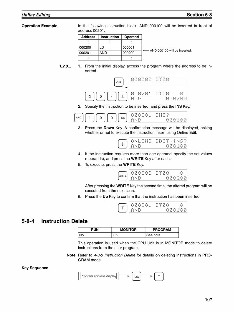
Online Editing Section 5-8
Operation Example In the following instruction block, AND 000100 will be inserted in front ofaddress 00201.
1,2,3... 1. From the initial display, access the program where the address to be in-serted.
…
2. Specify the instruction to be inserted, and press the INS Key.
3. Press the Down Key. A confirmation message will be displayed, askingwhether or not to execute the instruction insert using Online Edit.
4. If the instruction requires more than one operand, specify the set values(operands), and press the WRITE Key after each.
5. To execute, press the WRITE Key.
After pressing the WRITE Key the second time, the altered program will beexecuted from the next scan.
6. Press the Up Key to confirm that the instruction has been inserted.
5-8-4 Instruction Delete
This operation is used when the CPU Unit is in MONITOR mode to deleteinstructions from the user program.
Note Refer to 4-3-3 Instruction Delete for details on deleting instructions in PRO-GRAM mode.
Key Sequence
Address Instruction Operand
: : :
000200 LD 000001
000201 AND 000200
: : :
AND 000100 will be inserted.
CLR000000 CT00
2 0 1 ↓000201 CT00 0
AND 000200
AND 1 0 0 INS000201 INS?
AND 000100
↓ONLINE EDIT/INS?
AND 000100
WRITE000202 CT00 0
AND 000200
↑000201 CT00 0
AND 000100
RUN MONITOR PROGRAM
No OK See note.
Program address display DEL ↑
107

Online Editing Section 5-8
Operation Example In the following instruction block, AND 000200 will be deleted from address00201.
1,2,3... 1. From the initial display, access the program address of the instruction tobe deleted.
…
2. Delete the address.
3. To execute, press the Up Key. The next program address will be shiftedforwards.
• After pressing the Up Key the second time, the altered program will beexecuted from the next scan.
• When a multiple-operand instruction is deleted, the set values (oper-ands) will also be deleted.
5-8-5 Bit Address Change
This operation is used when the CPU Unit is in MONITOR mode to change bitaddresses used as operands in the user program.
Note Refer to 4-3-4 Bit Address Change for details on changing bit addresses inPROGRAM mode.
Key Sequence
Operation Example In the following instruction block, the bit address in the instruction at programaddress 00200 (LD 000001) will be changed to CIO 000002.
Address Instruction Operand
: : :
000200 LD 000001
000201 AND 000200
000202 OUT 000100
: : :
Delete
CLR000000 CT00
2 0 1 ↓000201 CT00 0
AND 000200
DELONLINE EDIT/DEL?
AND 000200
↑000201 DEL END0
OUT 000100
RUN MONITOR PROGRAM
No OK See note.
Input bit addressProgram address display WRITE WRITE
Address Instruction Operand
: : :
000200 LD 000001
000201 AND 000200
: : :
The bit address will be changed to CIO 000002.
108
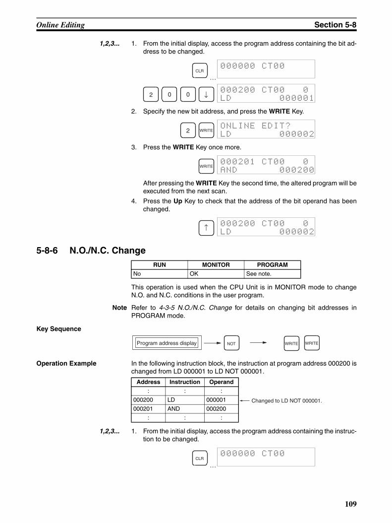
Online Editing Section 5-8
1,2,3... 1. From the initial display, access the program address containing the bit ad-dress to be changed.
…
2. Specify the new bit address, and press the WRITE Key.
3. Press the WRITE Key once more.
After pressing the WRITE Key the second time, the altered program will beexecuted from the next scan.
4. Press the Up Key to check that the address of the bit operand has beenchanged.
5-8-6 N.O./N.C. Change
This operation is used when the CPU Unit is in MONITOR mode to changeN.O. and N.C. conditions in the user program.
Note Refer to 4-3-5 N.O./N.C. Change for details on changing bit addresses inPROGRAM mode.
Key Sequence
Operation Example In the following instruction block, the instruction at program address 000200 ischanged from LD 000001 to LD NOT 000001.
1,2,3... 1. From the initial display, access the program address containing the instruc-tion to be changed.
…
CLR000000 CT00
2 0 0 ↓000200 CT00 0
LD 000001
2 WRITEONLINE EDIT?
LD 000002
WRITE000201 CT00 0
AND 000200
↑000200 CT00 0
LD 000002
RUN MONITOR PROGRAM
No OK See note.
Program address display WRITENOT WRITE
Address Instruction Operand
: : :
000200 LD 000001
000201 AND 000200
: : :
Changed to LD NOT 000001.
CLR000000 CT00
109
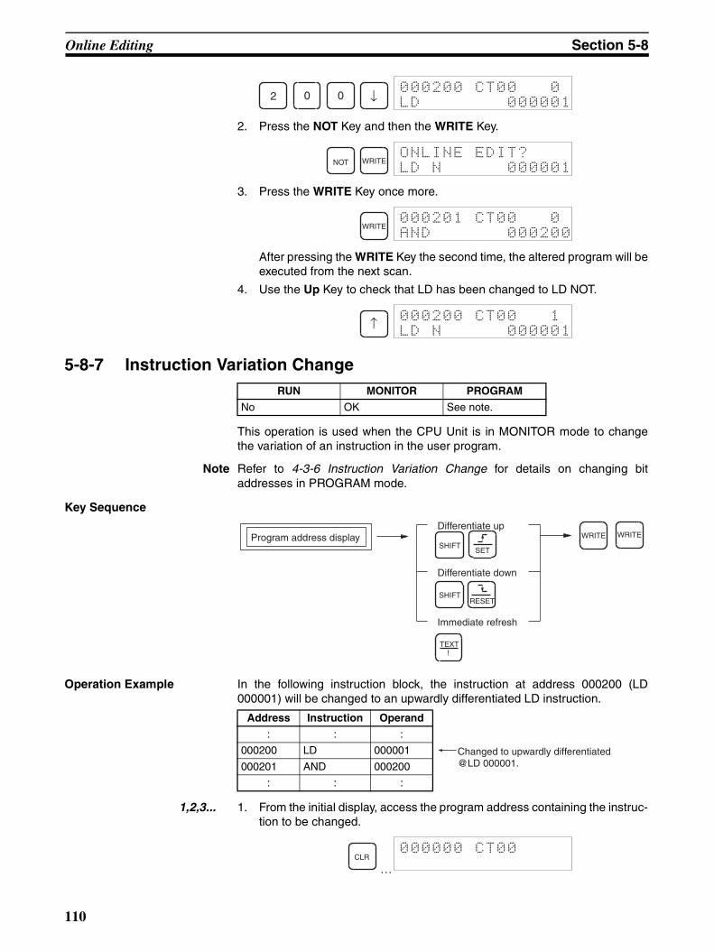
Online Editing Section 5-8
2. Press the NOT Key and then the WRITE Key.
3. Press the WRITE Key once more.
After pressing the WRITE Key the second time, the altered program will beexecuted from the next scan.
4. Use the Up Key to check that LD has been changed to LD NOT.
5-8-7 Instruction Variation Change
This operation is used when the CPU Unit is in MONITOR mode to changethe variation of an instruction in the user program.
Note Refer to 4-3-6 Instruction Variation Change for details on changing bitaddresses in PROGRAM mode.
Key Sequence
Operation Example In the following instruction block, the instruction at address 000200 (LD000001) will be changed to an upwardly differentiated LD instruction.
1,2,3... 1. From the initial display, access the program address containing the instruc-tion to be changed.
…
2 0 0 ↓000200 CT00 0
LD 000001
NOT WRITEONLINE EDIT?
LD N 000001
WRITE000201 CT00 0
AND 000200
↑000200 CT00 1
LD N 000001
RUN MONITOR PROGRAM
No OK See note.
Program address displayDifferentiate up
Differentiate down
Immediate refresh
SHIFT
SHIFT
!
WRITE WRITE
TEXT
SET
RESET
Address Instruction Operand
: : :
000200 LD 000001
000201 AND 000200
: : :
Changed to upwardly differentiated @LD 000001.
CLR000000 CT00
110

Online Editing Section 5-8
2. Specify the variation and press the WRITE Key.
3. Press the WRITE Key once more.
After pressing the WRITE Key the second time, the altered program will beexecuted from the next scan.
4. Use the Up Key to check the variation has changed.
5-8-8 Timer/Counter SV Change
Note Refer to 4-3-7 Timer/Counter SV Changes for details on changing timer/counter set values in PROGRAM mode.
Timer/Counter SV Change 1: Constant or WordThis operation is used to change the set value of a timer/counter in the userprogram.
Key Sequence
Operation Example The following example describes how to change the set value of TIM 0001.
1,2,3... 1. From the initial display, access the timer/counter for which the set value willbe changed.
…
2. Specify changing the set value from the above display.
3. The set value can be changed from the above display.
2 0 0 ↓000200 CT00 0
LD 000001
SHIFTSET
WRITEONLINE EDIT?
@LD 000001
WRITE000201 CT00 0
AND 000200
↑000200 CT00 0
@LD 000001
RUN MONITOR PROGRAM
No OK See note.
Designated constantsTimer/counter SV display WRITE
Designated words
CHG WRITE WRITE
CLR000000 CT00
TIM 1CF
SRCH
000201 CT00 FIND
TIM 0001
↓000201 TIM
SV #0100
CHG000201SV ?
#0100
111

Online Editing Section 5-8
Changing Constants
Input the constant from the above display.
Changing Word Address
Input the word address from the above display.
Timer/Counter SV Change 2: Fine Adjustment of ConstantThis operation is used to increment or decrement the set value of a timer/counter with a constant specified for the set value in the user program.
Key Sequence
Operation Example The following example describes how to adjust the constant specified as theset value for TIM 0001.
1,2,3... 1. From the initial display, access the timer/counter for which the set value willbe adjusted.
…
2. Specify changing the set values from the above display.
CONT
#1 2 0 WRITE WRITE
ONLINE EDIT?
SV #0120
WRITE000202 CT00
LD 000100
SHIFTCH
*DM 1 0 WRITE WRITE
ONLINE EDIT?
SV 0010
WRITE000202 CT00
LD 000100
Timer/counter SV display CHG CLR CLRCHG WRITE WRITE
↓
↑
CLR000000 CT00
TIM 1CF
SRCH
000201 CT00 FIND
TIM 0001
↓000201 TIM
SV #0020
CHG CHG000201SV U/D?
#0020
112

Online Editing Section 5-8
3. Incremented or decremented the constant using the Up and Down Keys.
or
4. Exit the operation. The new set value will be displayed.
↑ ↓ 000201SV U/D?
#0021
Incremented for the Down Key.
Decremented for the Up Key.
↓
↑
CLR CLR WRITEONLINE EDIT?
SV #0021
WRITE000202 CT00
LD 000100
113


115
SECTION 6Maintenance Operations
This section includes information on reading and setting the clock, reading cycle time, and reading and clearing errormessages.
6-1 Clock Read/Change. . . . . . . . . . . . . . . . . . . . . . . . . . . . . . . . . . . . . . . . . . . . . 116
6-2 Cycle Time Read. . . . . . . . . . . . . . . . . . . . . . . . . . . . . . . . . . . . . . . . . . . . . . . 117
6-3 Reading/Clearing Error Messages . . . . . . . . . . . . . . . . . . . . . . . . . . . . . . . . . 118

Clock Read/Change Section 6-1
6-1 Clock Read/Change
Note When the CPU Unit is in RUN mode, the clock can be read but can-not be changed.
This operation is used to read or set the CPU Unit’s internal clock.
• A battery is not installed in CS1-series PLCs when they are shipped.When the battery is installed in the CPU Unit, the CPU Unit clock will readas shown below. 00–01–00 = day, month, year; 00:00:00 = hours, min-utes, seconds; SUN(0) = Sunday.
• The CPU Unit’s internal clock will start when the following Clock Read/Change operation is executed, when the time is read/changed fromanother Peripheral Device, when a FINS command is used to read/change the time, or when the DATE instruction is executed from the userprogram.
• The time data for the CPU Unit’s internal clock is stored in the Calendar/Clock Area (A351 to 354) in the Auxiliary Area.
Key Sequence
Operation Example The following example shows how to set clock data for the first time.
1,2,3... 1. From the initial display, access the special function display.
…
2. Select 0: TIM.
3. To change the settings, press the CHG Key. When the CHG Key ispressed, the cursor will be displayed on the digit to be changed.
RUN MONITOR PROGRAM
See note OK OK
TIM 00-00-00
00:00:00: SUN(0)
MON DataInitial display SHIFT WRITEFUN 0
Specify: Yr Mth Day Hr Min S
CHG
↓
↑
CLR000000 CT00
FUN SHIFT MON0:CLOCK
0TIM 00-01-01
00:00:00: SUN(0)
116
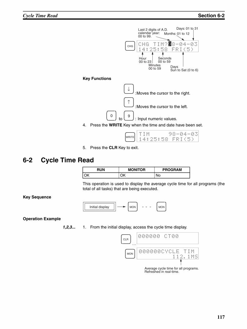
Cycle Time Read Section 6-2
Key Functions
:Moves the cursor to the right.
:Moves the cursor to the left.
to : Input numeric values.
4. Press the WRITE Key when the time and date have been set.
5. Press the CLR Key to exit.
6-2 Cycle Time Read
This operation is used to display the average cycle time for all programs (thetotal of all tasks) that are being executed.
Key Sequence
Operation Example
1,2,3... 1. From the initial display, access the cycle time display.
…
CHG
14:25:58 FRI(5)
Last 2 digits of A.D. calendar year: 00 to 99.
Months: 01 to 12
Days: 01 to 31
Hour00 to 23
Minutes00 to 59
Seconds00 to 59
DaysSun to Sat (0 to 6)
CHG TIM?98-04-03
↓
↑
0 9
WRITETIM 98-04-03
14:25:58 FRI(5)
RUN MONITOR PROGRAM
OK OK No
MONInitial display MON
CLR000000 CT00
MON 000000CYCLE TIM
112.1MS
Average cycle time for all programs.Refreshed in real-time.
117
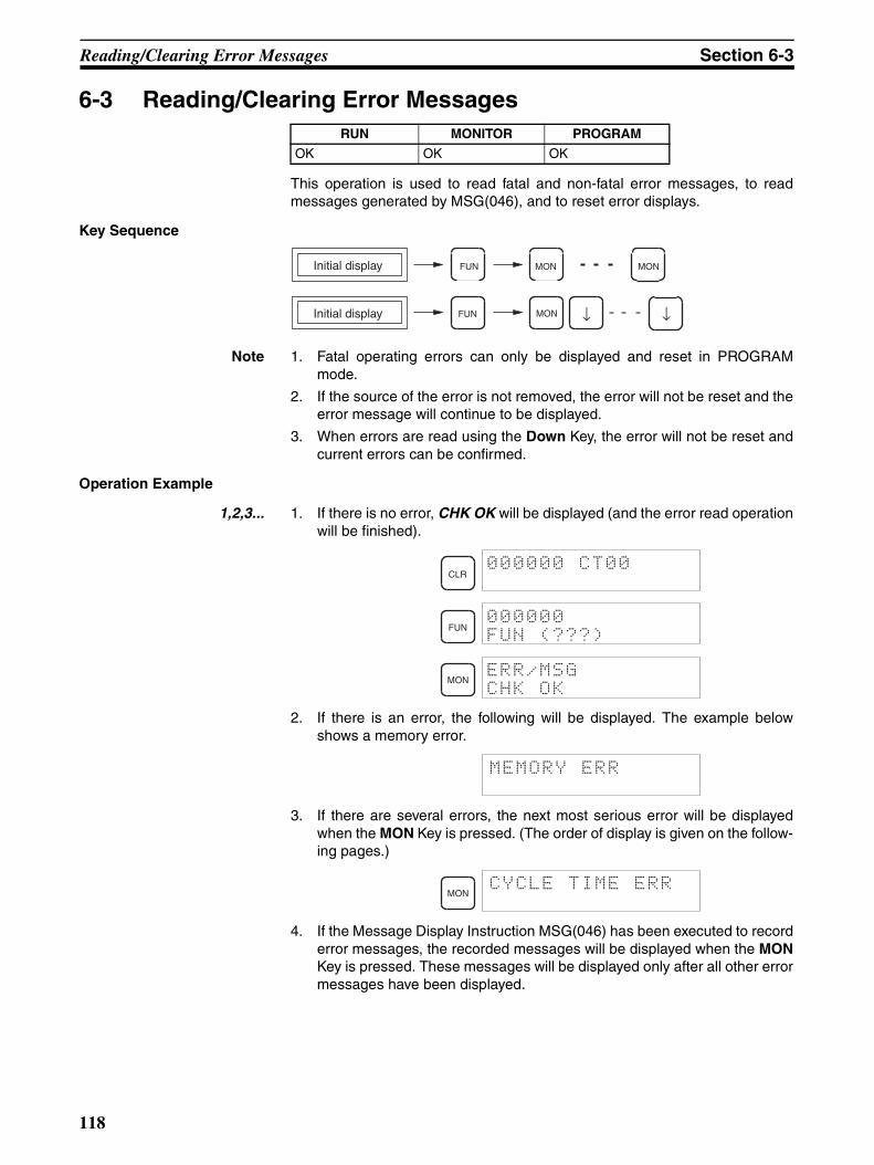
Reading/Clearing Error Messages Section 6-3
6-3 Reading/Clearing Error Messages
This operation is used to read fatal and non-fatal error messages, to readmessages generated by MSG(046), and to reset error displays.
Key Sequence
Note 1. Fatal operating errors can only be displayed and reset in PROGRAMmode.
2. If the source of the error is not removed, the error will not be reset and theerror message will continue to be displayed.
3. When errors are read using the Down Key, the error will not be reset andcurrent errors can be confirmed.
Operation Example
1,2,3... 1. If there is no error, CHK OK will be displayed (and the error read operationwill be finished).
2. If there is an error, the following will be displayed. The example belowshows a memory error.
3. If there are several errors, the next most serious error will be displayedwhen the MON Key is pressed. (The order of display is given on the follow-ing pages.)
4. If the Message Display Instruction MSG(046) has been executed to recorderror messages, the recorded messages will be displayed when the MONKey is pressed. These messages will be displayed only after all other errormessages have been displayed.
RUN MONITOR PROGRAM
OK OK OK
MONInitial display FUN MON
Initial display MONFUN ↓ ↓
CLR000000 CT00
FUN000000
FUN (???)
MONERR/MSG
CHK OK
MEMORY ERR
MONCYCLE TIME ERR
118

Reading/Clearing Error Messages Section 6-3
Note If the FAL instruction has being executed, messages recorded for theMSG(046) instruction will not be displayed until the cause of FAL ex-ecution has been removed.
5. When all error messages and MSG(046) messages have been cleared,the following message will be displayed.
Error MessagesWhen CPU Unit operation is not possible, the following message will be dis-played.
When several errors have occurred at the same time, the error messages willbe displayed in order from 1 to 21, as listed below. (In order from the mostserious to least serious.)
Fatal Operating Errors
1,2,3... 1. Memory Error
2. I/O Bus Error
3. Unit Number Duplication Error
4. Fatal Inner Board Error
5. Too Many I/O Points
6. I/O Setting Error
MONMSG
MATERIAL SHORT
MONERR/MSG
CHK OK
CPU WAIT'G
MEMORY ERR
I/O BUS ERR
Rack No.
f
UNIT No. DPL ERR
RACK No. DPL ERR
FATAL INNER ERR
TOO MANY I/O PNT
I/O SET ERR
119
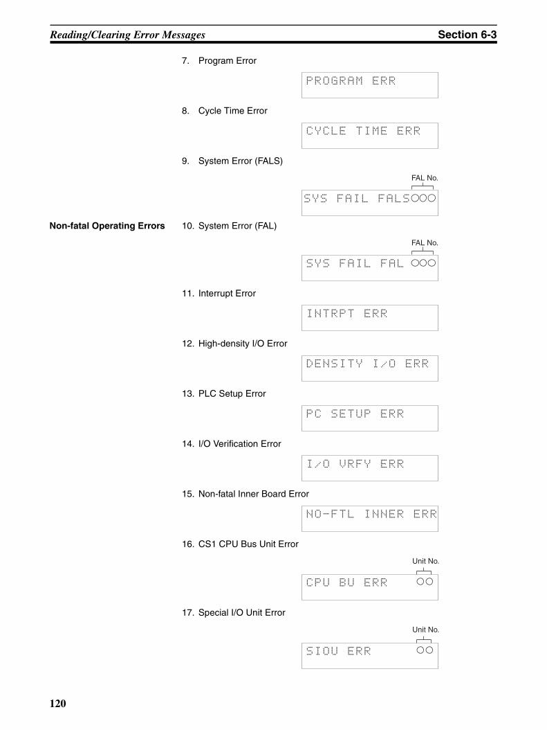
Reading/Clearing Error Messages Section 6-3
7. Program Error
8. Cycle Time Error
9. System Error (FALS)
Non-fatal Operating Errors 10. System Error (FAL)
11. Interrupt Error
12. High-density I/O Error
13. PLC Setup Error
14. I/O Verification Error
15. Non-fatal Inner Board Error
16. CS1 CPU Bus Unit Error
17. Special I/O Unit Error
PROGRAM ERR
CYCLE TIME ERR
SYS FAIL FALS
FAL No.
SYS FAIL FAL
FAL No.
INTRPT ERR
DENSITY I/O ERR
PC SETUP ERR
I/O VRFY ERR
NO-FTL INNER ERR
CPU BU ERR
Unit No.
SIOU ERR
Unit No.
120
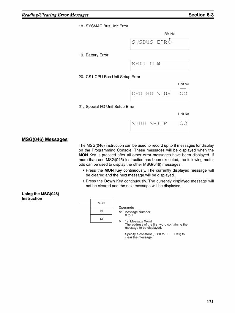
Reading/Clearing Error Messages Section 6-3
18. SYSMAC Bus Unit Error
19. Battery Error
20. CS1 CPU Bus Unit Setup Error
21. Special I/O Unit Setup Error
MSG(046) MessagesThe MSG(046) instruction can be used to record up to 8 messages for displayon the Programming Console. These messages will be displayed when theMON Key is pressed after all other error messages have been displayed. Ifmore than one MSG(046) instruction has been executed, the following meth-ods can be used to display the other MSG(046) messages.
• Press the MON Key continuously. The currently displayed message willbe cleared and the next message will be displayed.
• Press the Down Key continuously. The currently displayed message willnot be cleared and the next message will be displayed.
Using the MSG(046) Instruction
SYSBUS ERR
RM No.
BATT LOW
CPU BU STUP
Unit No.
SIOU SETUP
Unit No.
MSG
N
M
OperandsN: Message Number
0 to 7
M: 1st Message WordThe address of the first word containing the message to be displayed.
Specify a constant (0000 to FFFF Hex) to clear the message.
121
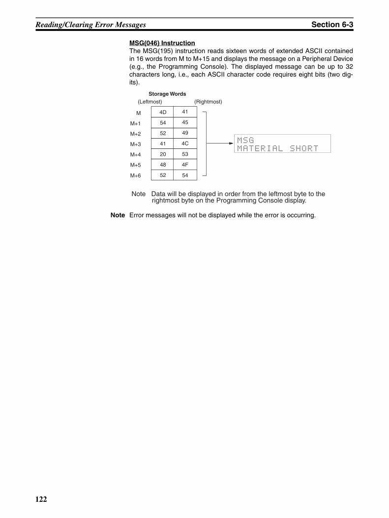
Reading/Clearing Error Messages Section 6-3
MSG(046) InstructionThe MSG(195) instruction reads sixteen words of extended ASCII containedin 16 words from M to M+15 and displays the message on a Peripheral Device(e.g., the Programming Console). The displayed message can be up to 32characters long, i.e., each ASCII character code requires eight bits (two dig-its).
Note Error messages will not be displayed while the error is occurring.
MSG
MATERIAL SHORT
Storage Words(Leftmost) (Rightmost)
M
M+1
M+2
M+3
M+4
M+5
M+6
4D
54
52
41
20
48
52
41
45
49
4C
53
4F
54
Note Data will be displayed in order from the leftmost byte to the rightmost byte on the Programming Console display.
122
123
SECTION 7Memory Card Operations
This section provides information on how to format Memory Cards before use, and procedures for transferring databetween Memory Cards and the CPU Unit.
7-1 File Memory Operations . . . . . . . . . . . . . . . . . . . . . . . . . . . . . . . . . . . . . . . . . 124
7-2 Memory Card Format . . . . . . . . . . . . . . . . . . . . . . . . . . . . . . . . . . . . . . . . . . . 125
7-3 File Write . . . . . . . . . . . . . . . . . . . . . . . . . . . . . . . . . . . . . . . . . . . . . . . . . . . . 126
7-4 File Read . . . . . . . . . . . . . . . . . . . . . . . . . . . . . . . . . . . . . . . . . . . . . . . . . . . . . 130
7-5 File Verify . . . . . . . . . . . . . . . . . . . . . . . . . . . . . . . . . . . . . . . . . . . . . . . . . . . . 134
7-6 File Delete . . . . . . . . . . . . . . . . . . . . . . . . . . . . . . . . . . . . . . . . . . . . . . . . . . . . 137

File Memory Operations Section 7-1
7-1 File Memory OperationsFile memory operations read/write CPU Unit file memory (Memory Card orEM File Memory. It is possible to read/write the following types of data.
• All user programs
• I/O memory areas
• Parameter Areas (e.g., PLC Setup)
Note I/O name table and block comments cannot be saved to file memory.
File Memory Types
Note I/O name table files (extension .SBL) and block comment files (extension.RGL), cannot be handled from the Programming Console.
For details on how to specify the starting bank for EM area file memory, referto Section Section 8 PLC Setup Procedure.
Overview of Memory Card/EM File Memory Operations
Memory type Data recognized by CPU Unit
Memory capacity Model
1. UM Area
2. I/O memory within specified ranges3. Parameter Areas (e.g., PLC Setup)4. I/O name table (See note)
5. Block comments (See note)
8 Mbytes HMC-EF861
15 Mbytes HMC-EF171
30 Mbytes HMC-EF371
1. UM Area2. I/O memory within specified ranges
3. Parameter Areas (e.g., PLC Setup)4. I/O name table (See note)5. Block comments (See note)
From the specified EM bank to the last bank (as spec-ified in PLC Setup).
---
Memory Card (flash memory)
EM areaBank 0
:Bank n
:Bank C
EM File Memory (RAM)
EM File Memory(From bank n onwards.)
Operation Details
Memory Card Format Formats Memory Cards or EM File Memory.
---
File Write Transfers files from the PLC to a Memory Card or EM File Mem-ory.
See note.
File Read Transfers files from a Memory Card or EM File Memory to the PLC.
File Verify Compares Memory Card or EM File Memory data with CPU Unit internal data.
File Delete Deletes the contents of Memory Card or EM File Memory data.
124

Memory Card Format Section 7-2
Note The memory areas that can be transferred or deleted are as follows:
With CS1-series PLCs, Memory Cards and the specified range of EM FileMemory can be used as file memory. Regardless of whether it’s the UM Area,I/O memory or the Parameter Areas (e.g., PLC Setup), all data is saved asfiles.
7-2 Memory Card Format
This operation is used to format Memory Cards or EM File Memory.
Key Sequence
Operation Example
1,2,3... 1. From the initial display, access the Memory Card operations menu.
…
UM Area
I/O memory CIO Area Specify the transfer start address and end address for each memory area.Note One area = 1 file
Work Area (WR)
Holding Bit Area (HR)
Auxiliary Bit Area (AR)
DM Area (DM)
EM Area (EM)
Parameter Areas (e.g., PLC Setup)
xxxxxxxx.OBJ
Memory area
UM Area
I/O memory
Parameter Areas (PLC Setup, I/O tables, etc.)
File memory
Memory Card
EM File Memory
CIO
HR
WR
AR
DM
EM
xxxxxxxx.IOM
xxxxxxxx.STD
CPU Unit
RUN MONITOR PROGRAM
OK OK OK
PasswordInitial display SHIFT WRITEFUN 2
Fixed: 9713 (Memory Card)8426 (EM File Memory)
CONT# ↓
CLR000000 CT00
125
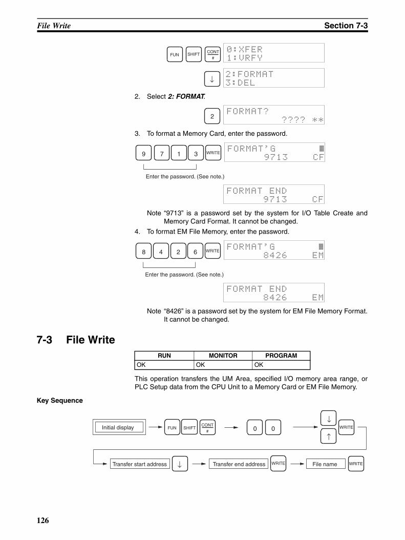
File Write Section 7-3
2. Select 2: FORMAT.
3. To format a Memory Card, enter the password.
Note “9713” is a password set by the system for I/O Table Create andMemory Card Format. It cannot be changed.
4. To format EM File Memory, enter the password.
Note “8426” is a password set by the system for EM File Memory Format.It cannot be changed.
7-3 File Write
This operation transfers the UM Area, specified I/O memory area range, orPLC Setup data from the CPU Unit to a Memory Card or EM File Memory.
Key Sequence
FUN SHIFT CONT
#
0:XFER
1:VRFY
↓2:FORMAT
3:DEL
2FORMAT?
???? **
FORMAT'G ~ 9713 CF
Enter the password. (See note.)
9 7 1 3 WRITE
FORMAT END
9713 CF
FORMAT'G ~ 8426 EM
Enter the password. (See note.)
WRITE8 4 2 6
FORMAT END
8426 EM
RUN MONITOR PROGRAM
OK OK OK
Transfer start address
Initial display SHIFT
WRITE
FUN 0 0
Transfer end address File name
CONT
#WRITE
WRITE
↓
↑
↓
126
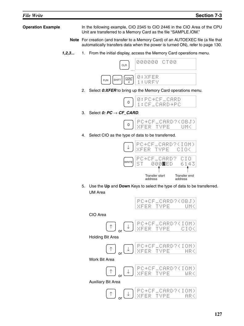
File Write Section 7-3
Operation Example In the following example, CIO 2345 to CIO 2446 in the CIO Area of the CPUUnit are transferred to a Memory Card as the file “SAMPLE.IOM.”
Note For creation (and transfer to a Memory Card) of an AUTOEXEC file (a file thatautomatically transfers data when the power is turned ON), refer to page 130.
1,2,3... 1. From the initial display, access the Memory Card operations menu.
…
2. Select 0:XFER to bring up the Memory Card operations menu.
3. Select 0: PC → CF_CARD.
4. Select CIO as the type of data to be transferred.
5. Use the Up and Down Keys to select the type of data to be transferred.
UM Area
CIO Area
or
Holding Bit Area
or
Work Bit Area
or
Auxiliary Bit Area
or
CLR000000 CT00
FUN SHIFT CONT
#
0:XFER
1:VRFY
00:PC~CF_CARD
1:CF_CARD~PC
0PC~CF_CARD?(OBJ)
XFER TYPE UM<
↓PC~CF_CARD?(IOM)
XFER TYPE CIO<
WRITEPC~CF_CARD? CIO
ST 0000ED 6143
Transfer start address
Transfer end address
PC~CF_CARD?(OBJ)
XFER TYPE UM<
↑ ↓PC~CF_CARD?(IOM)
XFER TYPE CIO<
↑ ↓PC~CF_CARD?(IOM)
XFER TYPE HR<
↑ ↓PC~CF_CARD?(IOM)
XFER TYPE WR<
↑ ↓PC~CF_CARD?(IOM)
XFER TYPE AR<
127
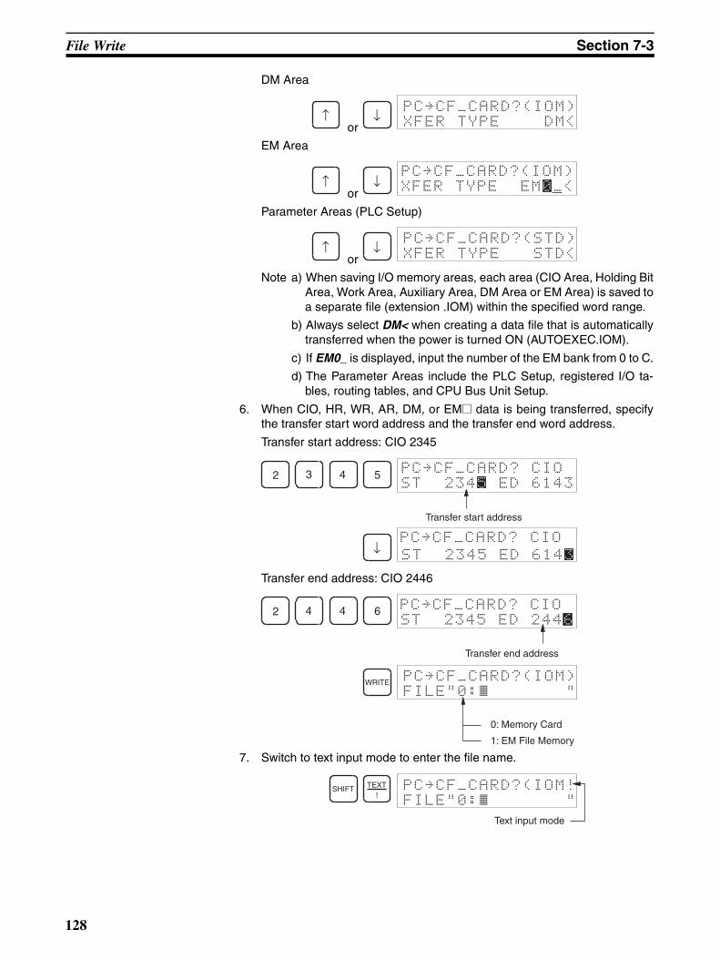
File Write Section 7-3
DM Area
or
EM Area
or
Parameter Areas (PLC Setup)
or
Note a) When saving I/O memory areas, each area (CIO Area, Holding BitArea, Work Area, Auxiliary Area, DM Area or EM Area) is saved toa separate file (extension .IOM) within the specified word range.
b) Always select DM< when creating a data file that is automaticallytransferred when the power is turned ON (AUTOEXEC.IOM).
c) If EM0_ is displayed, input the number of the EM bank from 0 to C.
d) The Parameter Areas include the PLC Setup, registered I/O ta-bles, routing tables, and CPU Bus Unit Setup.
6. When CIO, HR, WR, AR, DM, or EM@ data is being transferred, specifythe transfer start word address and the transfer end word address.
Transfer start address: CIO 2345
Transfer end address: CIO 2446
7. Switch to text input mode to enter the file name.
↑ ↓PC~CF_CARD?(IOM)
XFER TYPE DM<
↑ ↓PC~CF_CARD?(IOM)
XFER TYPE EM0_<
↑ ↓PC~CF_CARD?(STD)
XFER TYPE STD<
2 3 4 5 PC~CF_CARD? CIO
ST 2345 ED 6143
Transfer start address
↓PC~CF_CARD? CIO
ST 2345 ED 6143
2 4 4 6 PC~CF_CARD? CIO
Transfer end address
ST 2345 ED 2446
WRITE PC~CF_CARD?(IOM)
FILE"0:~ "
0: Memory Card
1: EM File Memory
SHIFT TEXT!
PC~CF_CARD?(IOM!
FILE"0:~ "
Text input mode
128
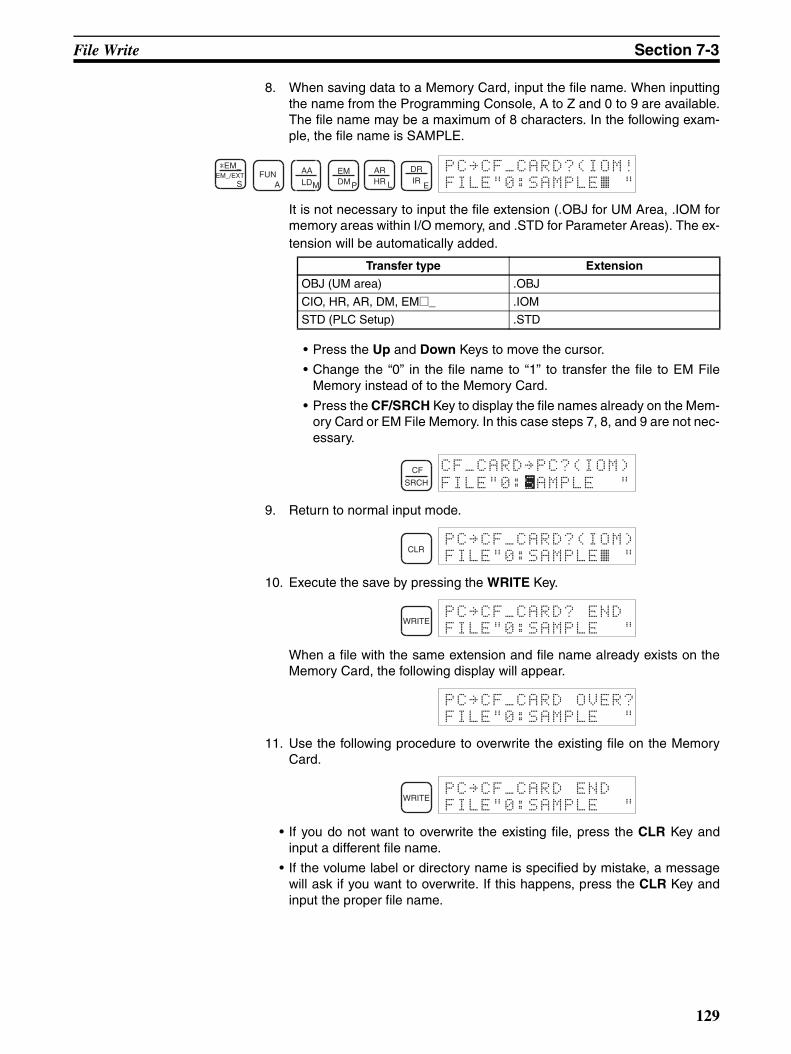
File Write Section 7-3
8. When saving data to a Memory Card, input the file name. When inputtingthe name from the Programming Console, A to Z and 0 to 9 are available.The file name may be a maximum of 8 characters. In the following exam-ple, the file name is SAMPLE.
It is not necessary to input the file extension (.OBJ for UM Area, .IOM formemory areas within I/O memory, and .STD for Parameter Areas). The ex-tension will be automatically added.
• Press the Up and Down Keys to move the cursor.
• Change the “0” in the file name to “1” to transfer the file to EM FileMemory instead of to the Memory Card.
• Press the CF/SRCH Key to display the file names already on the Mem-ory Card or EM File Memory. In this case steps 7, 8, and 9 are not nec-essary.
9. Return to normal input mode.
10. Execute the save by pressing the WRITE Key.
When a file with the same extension and file name already exists on theMemory Card, the following display will appear.
11. Use the following procedure to overwrite the existing file on the MemoryCard.
• If you do not want to overwrite the existing file, press the CLR Key andinput a different file name.
• If the volume label or directory name is specified by mistake, a messagewill ask if you want to overwrite. If this happens, press the CLR Key andinput the proper file name.
*EM_EM_/EXT
SFUN
A
AALDM
EMDMP
ARHR L
DRIR
E FILE"0:SAMPLE~ "PC~CF_CARD?(IOM!
Transfer type Extension
OBJ (UM area) .OBJ
CIO, HR, AR, DM, EM@_ .IOM
STD (PLC Setup) .STD
CF
SRCH FILE"0:SAMPLE "
CF_CARD~PC?(IOM)
CLRFILE"0:SAMPLE~ "PC~CF_CARD?(IOM)
WRITEFILE"0:SAMPLE "
PC~CF_CARD? END
FILE"0:SAMPLE "
PC~CF_CARD OVER?
WRITEFILE"0:SAMPLE "
PC~CF_CARD END
129
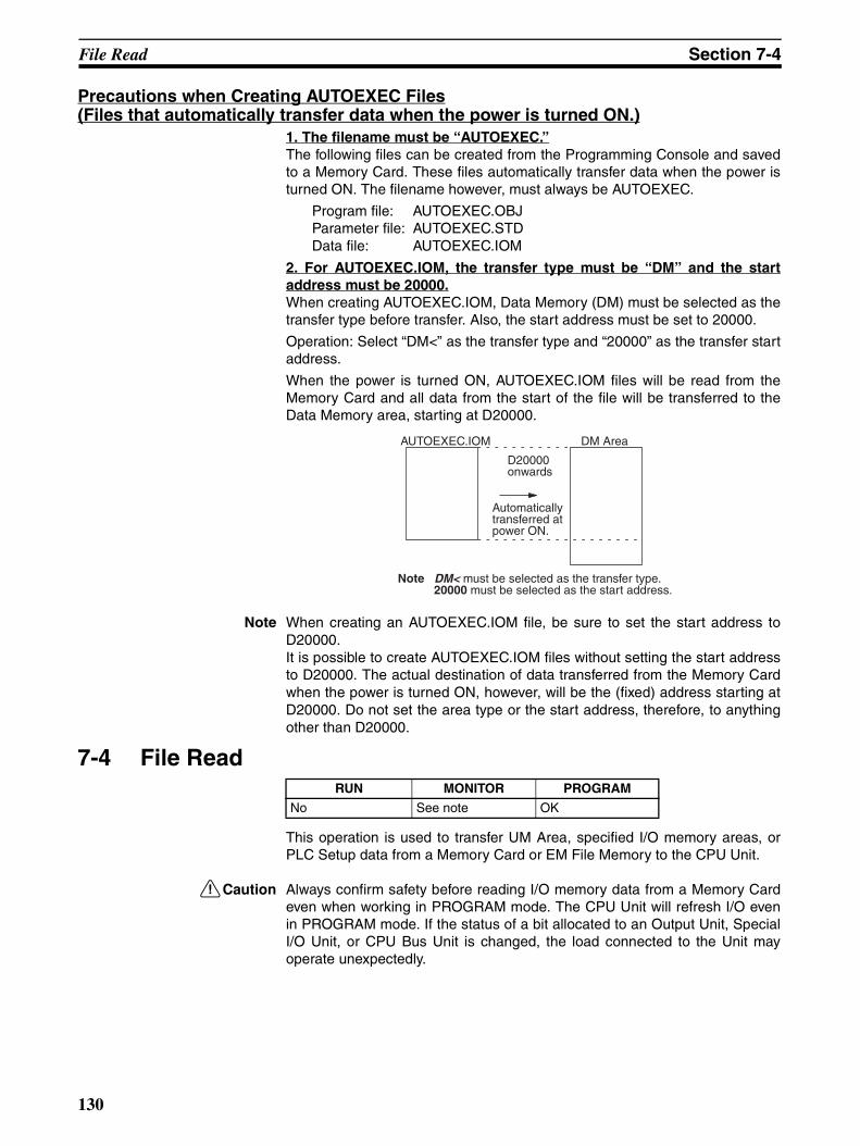
File Read Section 7-4
Precautions when Creating AUTOEXEC Files(Files that automatically transfer data when the power is turned ON.)
1. The filename must be “AUTOEXEC.”The following files can be created from the Programming Console and savedto a Memory Card. These files automatically transfer data when the power isturned ON. The filename however, must always be AUTOEXEC.
Program file: AUTOEXEC.OBJParameter file: AUTOEXEC.STDData file: AUTOEXEC.IOM
2. For AUTOEXEC.IOM, the transfer type must be “DM” and the startaddress must be 20000.When creating AUTOEXEC.IOM, Data Memory (DM) must be selected as thetransfer type before transfer. Also, the start address must be set to 20000.
Operation: Select “DM<” as the transfer type and “20000” as the transfer startaddress.
When the power is turned ON, AUTOEXEC.IOM files will be read from theMemory Card and all data from the start of the file will be transferred to theData Memory area, starting at D20000.
Note When creating an AUTOEXEC.IOM file, be sure to set the start address toD20000.It is possible to create AUTOEXEC.IOM files without setting the start addressto D20000. The actual destination of data transferred from the Memory Cardwhen the power is turned ON, however, will be the (fixed) address starting atD20000. Do not set the area type or the start address, therefore, to anythingother than D20000.
7-4 File Read
This operation is used to transfer UM Area, specified I/O memory areas, orPLC Setup data from a Memory Card or EM File Memory to the CPU Unit.
!Caution Always confirm safety before reading I/O memory data from a Memory Cardeven when working in PROGRAM mode. The CPU Unit will refresh I/O evenin PROGRAM mode. If the status of a bit allocated to an Output Unit, SpecialI/O Unit, or CPU Bus Unit is changed, the load connected to the Unit mayoperate unexpectedly.
AUTOEXEC.IOM DM Area
D20000 onwards
Automatically transferred at power ON.
Note DM< must be selected as the transfer type.20000 must be selected as the start address.
RUN MONITOR PROGRAM
No See note OK
130
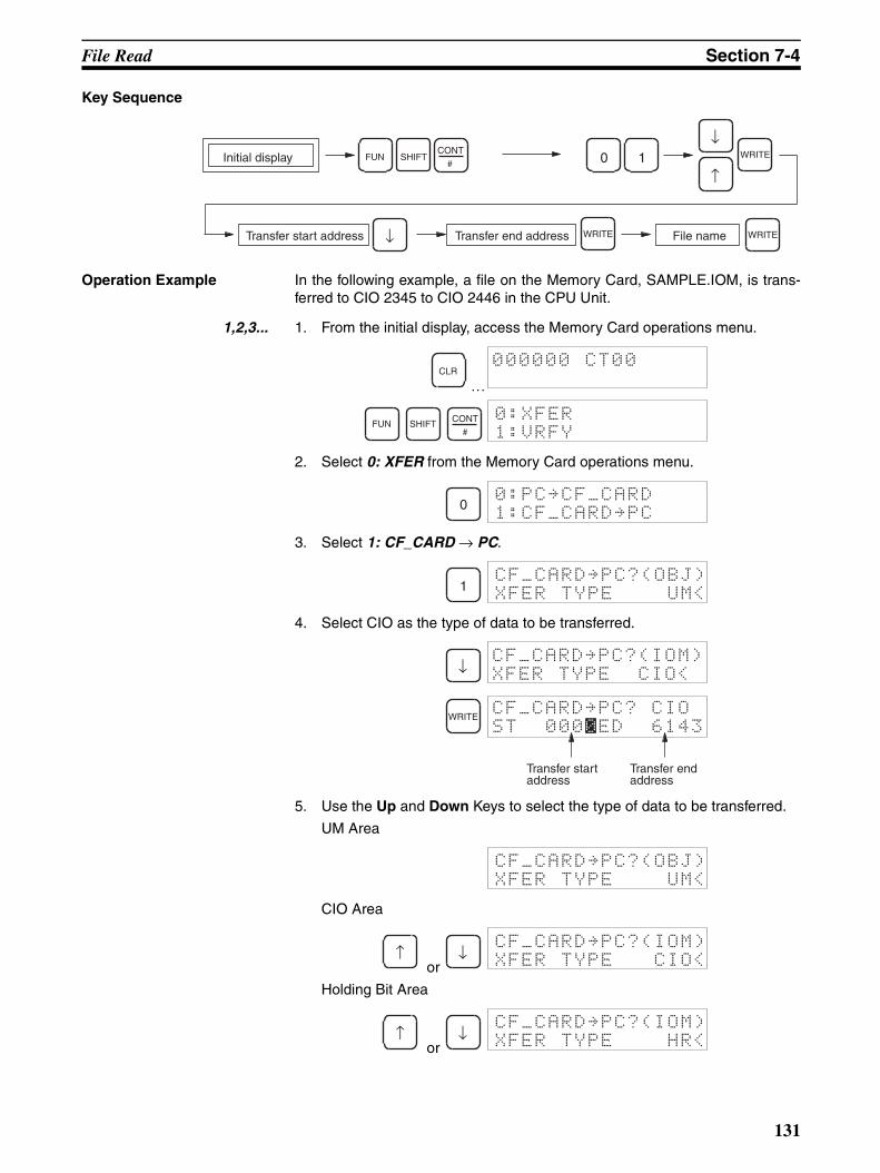
File Read Section 7-4
Key Sequence
Operation Example In the following example, a file on the Memory Card, SAMPLE.IOM, is trans-ferred to CIO 2345 to CIO 2446 in the CPU Unit.
1,2,3... 1. From the initial display, access the Memory Card operations menu.
…
2. Select 0: XFER from the Memory Card operations menu.
3. Select 1: CF_CARD → PC.
4. Select CIO as the type of data to be transferred.
5. Use the Up and Down Keys to select the type of data to be transferred.
UM Area
CIO Area
or
Holding Bit Area
or
Transfer start address
Initial display SHIFT
WRITE
FUN 0
Transfer end address File name
1CONT
#WRITE
WRITE
↓
↑
↓
CLR000000 CT00
FUN SHIFT CONT
#
0:XFER
1:VRFY
00:PC~CF_CARD
1:CF_CARD~PC
1CF_CARD~PC?(OBJ)
XFER TYPE UM<
↓CF_CARD~PC?(IOM)
XFER TYPE CIO<
WRITECF_CARD~PC? CIO
ST 0000ED 6143
Transfer start address
Transfer end address
CF_CARD~PC?(OBJ)
XFER TYPE UM<
↑ ↓CF_CARD~PC?(IOM)
XFER TYPE CIO<
↑ ↓CF_CARD~PC?(IOM)
XFER TYPE HR<
131
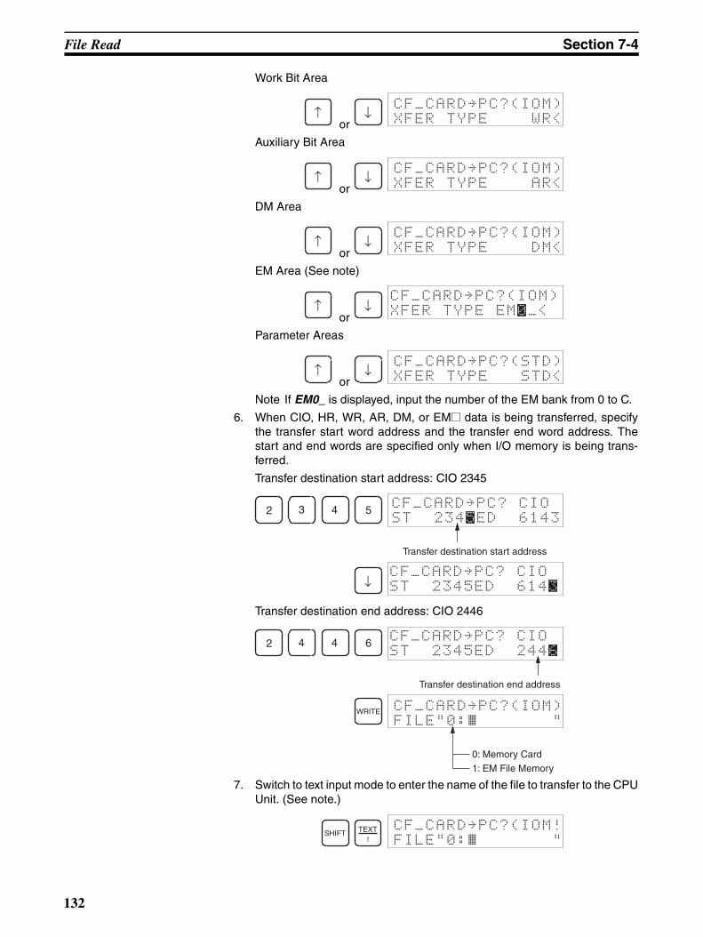
File Read Section 7-4
Work Bit Area
or
Auxiliary Bit Area
or
DM Area
or
EM Area (See note)
or
Parameter Areas
or
Note If EM0_ is displayed, input the number of the EM bank from 0 to C.
6. When CIO, HR, WR, AR, DM, or EM@ data is being transferred, specifythe transfer start word address and the transfer end word address. Thestart and end words are specified only when I/O memory is being trans-ferred.
Transfer destination start address: CIO 2345
Transfer destination end address: CIO 2446
7. Switch to text input mode to enter the name of the file to transfer to the CPUUnit. (See note.)
↑ ↓CF_CARD~PC?(IOM)
XFER TYPE WR<
↑ ↓CF_CARD~PC?(IOM)
XFER TYPE AR<
↑ ↓CF_CARD~PC?(IOM)
XFER TYPE DM<
↑ ↓CF_CARD~PC?(IOM)
XFER TYPE EM0_<
↑ ↓CF_CARD~PC?(STD)
XFER TYPE STD<
2 3 4 5 CF_CARD~PC? CIO
ST 2345ED 6143
Transfer destination start address
↓CF_CARD~PC? CIO
ST 2345ED 6143
2 4 4 6 CF_CARD~PC? CIO
Transfer destination end address
ST 2345ED 2446
WRITE CF_CARD~PC?(IOM)
FILE"0:~ "
0: Memory Card
1: EM File Memory
SHIFT TEXT!
CF_CARD~PC?(IOM!
FILE"0:~ "
132
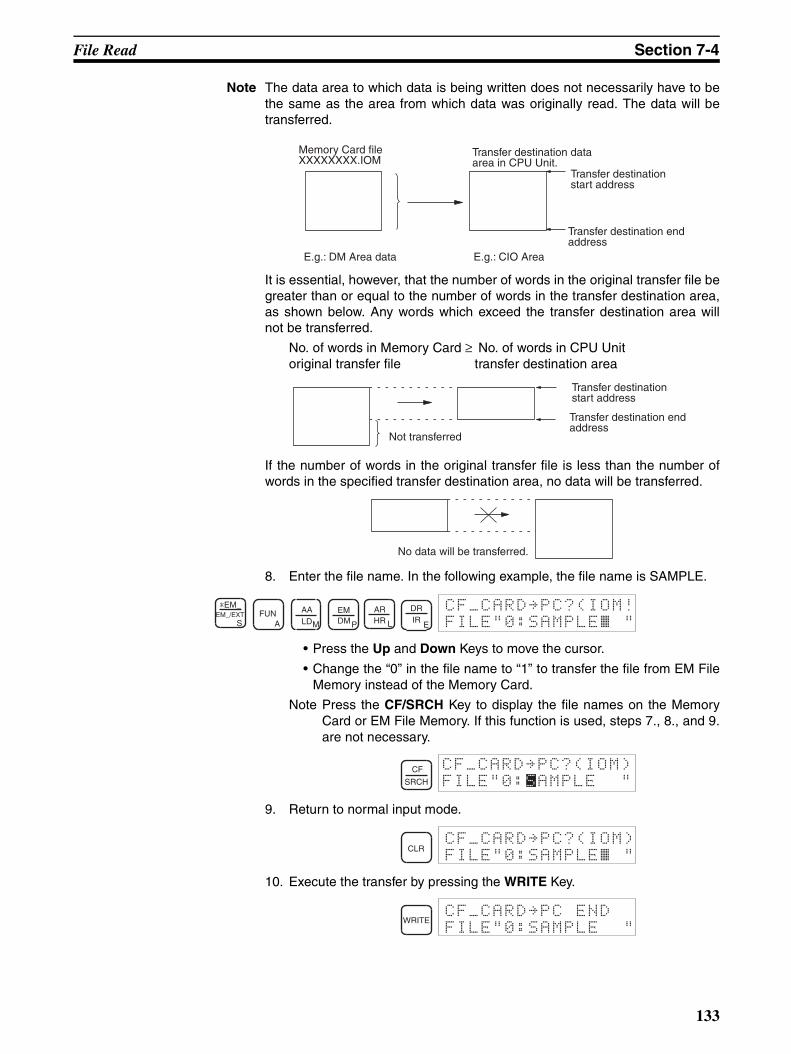
File Read Section 7-4
Note The data area to which data is being written does not necessarily have to bethe same as the area from which data was originally read. The data will betransferred.
It is essential, however, that the number of words in the original transfer file begreater than or equal to the number of words in the transfer destination area,as shown below. Any words which exceed the transfer destination area willnot be transferred.
No. of words in Memory Card ≥ No. of words in CPU Unitoriginal transfer file transfer destination area
If the number of words in the original transfer file is less than the number ofwords in the specified transfer destination area, no data will be transferred.
8. Enter the file name. In the following example, the file name is SAMPLE.
• Press the Up and Down Keys to move the cursor.
• Change the “0” in the file name to “1” to transfer the file from EM FileMemory instead of the Memory Card.
Note Press the CF/SRCH Key to display the file names on the MemoryCard or EM File Memory. If this function is used, steps 7., 8., and 9.are not necessary.
9. Return to normal input mode.
10. Execute the transfer by pressing the WRITE Key.
Memory Card fileXXXXXXXX.IOM
Transfer destination data area in CPU Unit.
E.g.: DM Area data
Transfer destination start address
Transfer destination end address
E.g.: CIO Area
Not transferred
Transfer destination start address
Transfer destination end address
No data will be transferred.
*EM_EM_/EXT
SFUN
A
AALDM
EMDMP
ARHR L
DRIR
E FILE"0:SAMPLE~ "CF_CARD~PC?(IOM!
CF
SRCH
CF_CARD~PC?(IOM)
FILE"0:SAMPLE "
CLRFILE"0:SAMPLE~ "CF_CARD~PC?(IOM)
WRITEFILE"0:SAMPLE "
CF_CARD~PC END
133
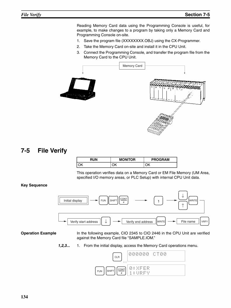
File Verify Section 7-5
Reading Memory Card data using the Programming Console is useful, forexample, to make changes to a program by taking only a Memory Card andProgramming Console on-site.
1. Save the program file (XXXXXXXX.OBJ) using the CX-Programmer.
2. Take the Memory Card on-site and install it in the CPU Unit.
3. Connect the Programming Console, and transfer the program file from theMemory Card to the CPU Unit.
7-5 File Verify
This operation verifies data on a Memory Card or EM File Memory (UM Area,specified I/O memory areas, or PLC Setup) with internal CPU Unit data.
Key Sequence
Operation Example In the following example, CIO 2345 to CIO 2446 in the CPU Unit are verifiedagainst the Memory Card file “SAMPLE.IOM.”
1,2,3... 1. From the initial display, access the Memory Card operations menu.
…
RUN MONITOR PROGRAM
OK OK OK
Memory Card
Verify start address
Initial display
VRFY
SHIFTFUN
Verify end address File name
1CONT
#WRITE
WRITE
↓
↑
↓
CLR000000 CT00
FUN SHIFT CONT
#
0:XFER
1:VRFY
134
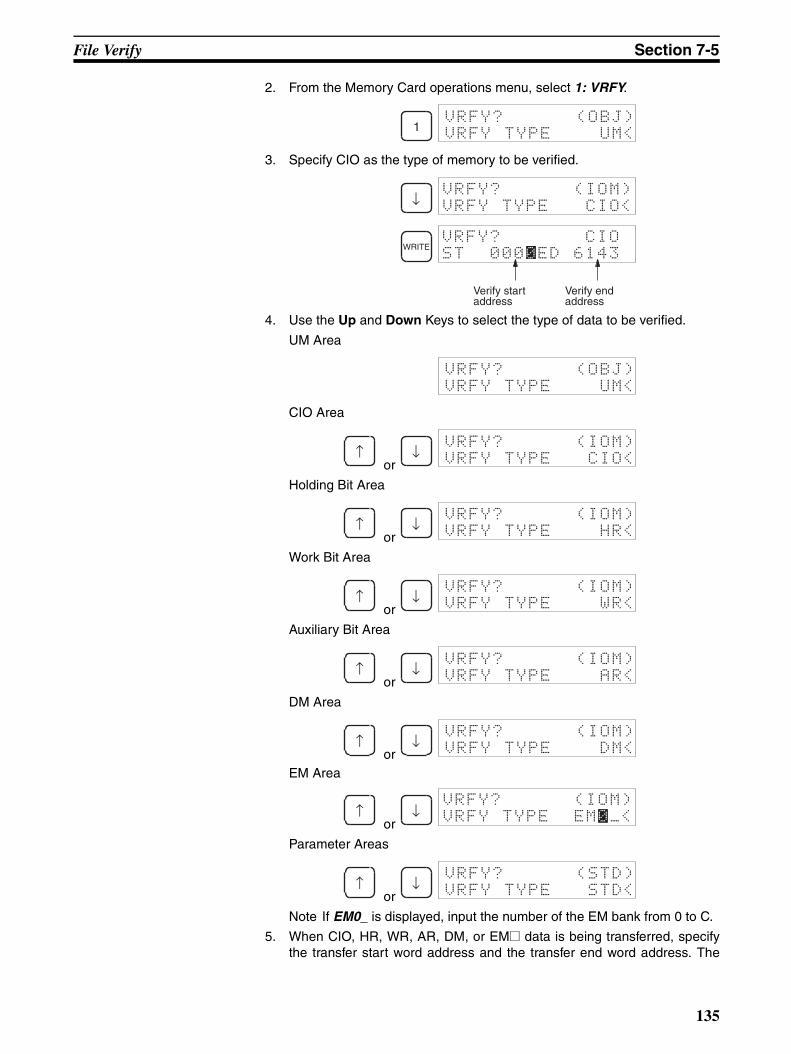
File Verify Section 7-5
2. From the Memory Card operations menu, select 1: VRFY.
3. Specify CIO as the type of memory to be verified.
4. Use the Up and Down Keys to select the type of data to be verified.
UM Area
CIO Area
or
Holding Bit Area
or
Work Bit Area
or
Auxiliary Bit Area
or
DM Area
or EM Area
or
Parameter Areas
or
Note If EM0_ is displayed, input the number of the EM bank from 0 to C.
5. When CIO, HR, WR, AR, DM, or EM@ data is being transferred, specifythe transfer start word address and the transfer end word address. The
1VRFY? (OBJ)
VRFY TYPE UM<
↓VRFY? (IOM)
VRFY TYPE CIO<
WRITEVRFY? CIO
ST 0000ED 6143
Verify start address
Verify end address
VRFY? (OBJ)
VRFY TYPE UM<
↑ ↓VRFY? (IOM)
VRFY TYPE CIO<
↑ ↓VRFY? (IOM)
VRFY TYPE HR<
↑ ↓VRFY? (IOM)
VRFY TYPE WR<
↑ ↓VRFY? (IOM)
VRFY TYPE AR<
↑ ↓VRFY? (IOM)
VRFY TYPE DM<
↑ ↓VRFY? (IOM)
VRFY TYPE EM0_<
↑ ↓VRFY? (STD)
VRFY TYPE STD<
135
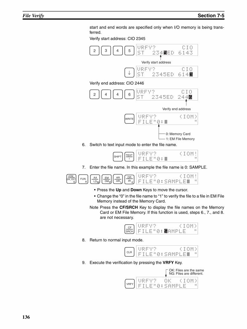
File Verify Section 7-5
start and end words are specified only when I/O memory is being trans-ferred.
Verify start address: CIO 2345
Verify end address: CIO 2446
6. Switch to text input mode to enter the file name.
7. Enter the file name. In this example the file name is 0: SAMPLE.
• Press the Up and Down Keys to move the cursor.
• Change the “0” in the file name to “1” to verify the file to a file in EM FileMemory instead of the Memory Card.
Note Press the CF/SRCH Key to display the file names on the MemoryCard or EM File Memory. If this function is used, steps 6., 7., and 8.are not necessary.
8. Return to normal input mode.
9. Execute the verification by pressing the VRFY Key.
2 3 4 5VRFY? CIO
ST 2345ED 6143
Verify start address
↓VRFY? CIO
ST 2345ED 61430
2 4 4 6 VRFY? CIO
Verify end address
ST 2345ED 2446
WRITE VRFY? (IOM)
FILE"0:~ "
0: Memory Card
1: EM File Memory
SHIFT TEXT!
VRFY? (IOM!
FILE"0:~ "
*EM_EM_/EXT
SFUN
A
AALDM
EMDMP
ARHR L
DRIR
E FILE"0:SAMPLE~ "VRFY? (IOM!
CF
SRCH
VRFY? (IOM)
FILE"0:SAMPLE "
CLRFILE"0:SAMPLE~ "VRFY? (IOM)
VRFYFILE"0:SAMPLE "
VRFY? OK (IOM)
OK: Files are the sameNG: Files are different.
136
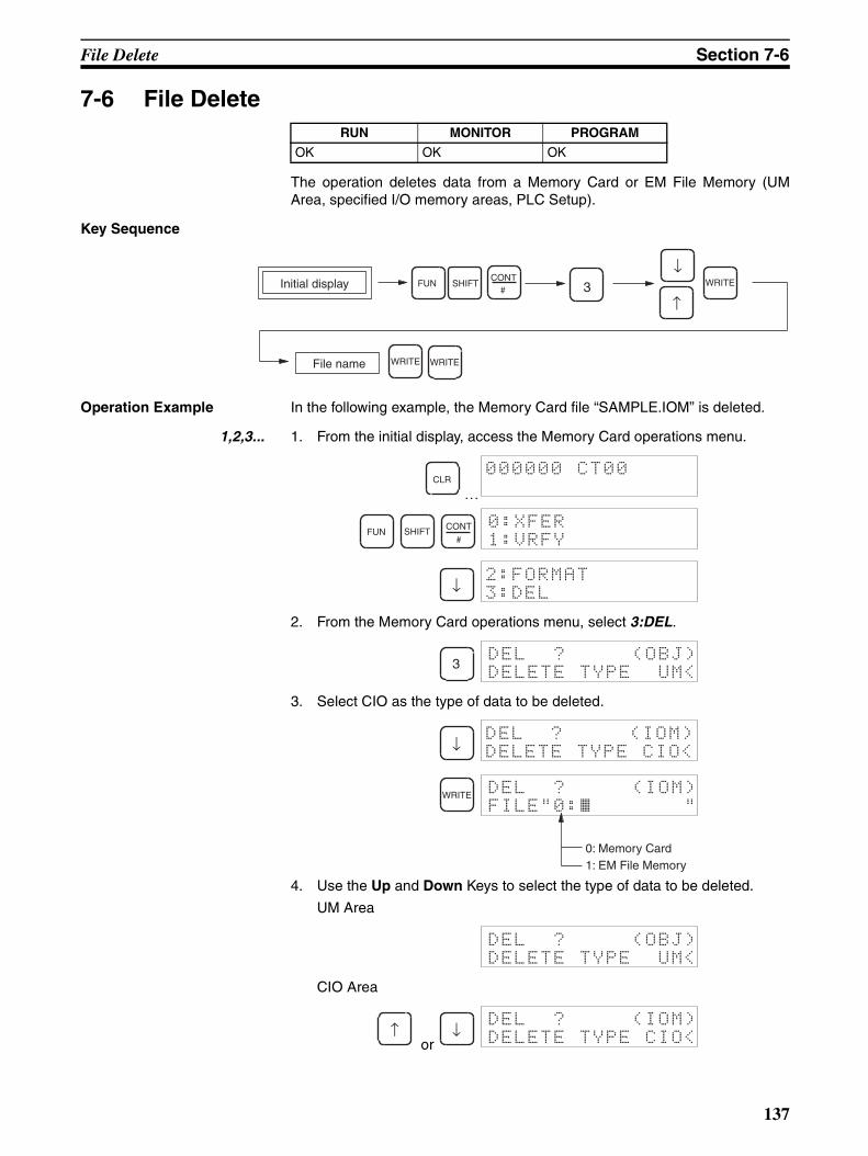
File Delete Section 7-6
7-6 File Delete
The operation deletes data from a Memory Card or EM File Memory (UMArea, specified I/O memory areas, PLC Setup).
Key Sequence
Operation Example In the following example, the Memory Card file “SAMPLE.IOM” is deleted.
1,2,3... 1. From the initial display, access the Memory Card operations menu.
…
2. From the Memory Card operations menu, select 3:DEL.
3. Select CIO as the type of data to be deleted.
4. Use the Up and Down Keys to select the type of data to be deleted.
UM Area
CIO Area
or
RUN MONITOR PROGRAM
OK OK OK
File name
Initial display SHIFTFUN 3CONT
#WRITE
WRITE WRITE
↓
↑
CLR000000 CT00
FUN SHIFT CONT
#
0:XFER
1:VRFY
↓2:FORMAT
3:DEL
3DEL ? (OBJ)
DELETE TYPE UM<
↓DEL ? (IOM)
DELETE TYPE CIO<
WRITE DEL ? (IOM)
FILE"0:~ "
0: Memory Card1: EM File Memory
DEL ? (OBJ)
DELETE TYPE UM<
↑ ↓DEL ? (IOM)
DELETE TYPE CIO<
137

File Delete Section 7-6
Holding Bit Area
or
Work Bit Area
or
Auxiliary Bit Area
or
DM Area
or
EM Area
or
Parameter Areas
or
Note If EM0_ is displayed, input the number of the EM bank from 0 to C.
5. Switch to text input mode to enter the file name.
6. Enter the file name. (See note.)
• Press the Up and Down Keys to move the cursor.
• Change the “0” in the file name to “1” to delete a file from EM File Mem-ory instead of the Memory Card.
Note Press the CF/SRCH Key to display the file names on the MemoryCard or EM File Memory. If this function is used, steps 5., 6., and 7.are not necessary.
File name search:
7. Return to normal input mode.
↑ ↓DEL ? (IOM)
DELETE TYPE HR<
↑ ↓DEL ? (IOM)
DELETE TYPE WR<
↑ ↓DEL ? (IOM)
DELETE TYPE AR<
↑ ↓DEL ? (IOM)
DELETE TYPE DM<
↑ ↓DEL ? (IOM)
DELETE TYPEEM0_<
↑ ↓DEL ? (STD)
DELETE TYPE STD<
SHIFT TEXT!
DEL ? (IOM!
FILE"0:~ "
*EM_EM_/EXT
SFUN
A
AALDM
EMDMP
ARHR L
DRIR
E FILE"0:SAMPLE~ "DEL ? (IOM!
CF
SRCH
DEL ? (IOM)
FILE"0:SAMPLE "
CLRFILE"0:SAMPLE~ "DEL ? (IOM)
138

File Delete Section 7-6
8. Confirm the file to be deleted.
9. Execute the deletion by pressing the WRITE Key.
WRITEFILE"0:SAMPLE "
DEL OK? (IOM)
WRITEFILE"0:SAMPLE "
DEL END (IOM)
139


141
SECTION 8PLC Setup Procedure
This section lists the settings in the PLC Setup.
8-1 PLC Setup Procedure . . . . . . . . . . . . . . . . . . . . . . . . . . . . . . . . . . . . . . . . . . . 142

PLC Setup Procedure Section 8-1
8-1 PLC Setup Procedure
Note When in RUN or MONITOR mode, contents of settings can be read, but set-ting cannot be performed.
This operation is used to read and write data from and to the PLC Setup Areain the CPU Unit.
Key Sequence
Operation Example 1 In the following example, the Startup mode setting (+081) is changed.
1,2,3... 1. From the initial display, access the PLC Setup display.
…
2. It is not necessary to input the Startup mode setting address, just select0:MODE.
3. Make changes to the settings.
RUN MONITOR PROGRAM
See note See note OK
Set value WRITEVRFYFUN CHG
Address1
0
↓
CLR000000 CT00
FUN VRFYPC SETUP
0:MODE 1:PC SYS
PC SETUP
+081 PRCN
PLC Setup address(+081: Startup mode changes) Current settings are displayed
(Corresponds to the operation mode of the Programming Con-sole.)
0
CHGPC SETUP ?
+081 PRCN PRCN
Possible changes are displayed in sequence
↓PC SETUP ?
+081 PRCN PRG
↓PC SETUP ?
+081 PRCN MON
↓PC SETUP ?
+081 PRCN RUN
142
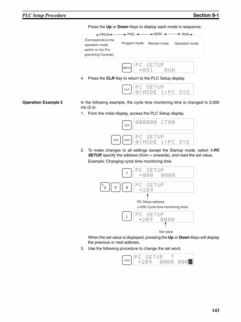
PLC Setup Procedure Section 8-1
Press the Up or Down Keys to display each mode in sequence.
4. Press the CLR Key to return to the PLC Setup display.
Operation Example 2 In the following example, the cycle time monitoring time is changed to 2,000ms (2 s).
1. From the initial display, access the PLC Setup display.
2. To make changes to all settings except the Startup mode, select 1:PCSETUP, specify the address (from + onwards), and read the set value.
Example: Changing cycle time monitoring time
When the set value is displayed, pressing the Up or Down Keys will displaythe previous or next address.
3. Use the following procedure to change the set word.
PRCN PRG MON RUN
(Corresponds to the
operation mode
switch on the Pro
gramming Console)
Program mode Monitor mode Operation mode
WRITEPC SETUP
+081 RUN
CLRPC SETUP
0:MODE 1:PC SYS
CLR000000 CT00
FUN VRFYPC SETUP
0:MODE 1:PC SYS
1PC SETUP
+000 0000
C2 0 9
PC SETUP
+209
PC Setup address
(+209: Cycle time monitoring time)
↓ PC SETUP
Set value
+209 0000
CHGPC SETUP ?
+209 0000 0000
143

PLC Setup Procedure Section 8-1
Example: Changing the value to 2,000 ms.
4. Press the CLR Key to return to the PLC Setup display.
8 0 SHIFTC
2 8PC SETUP ?
+209 0000 80C8
WRITEPC SETUP
+209 80C8
144
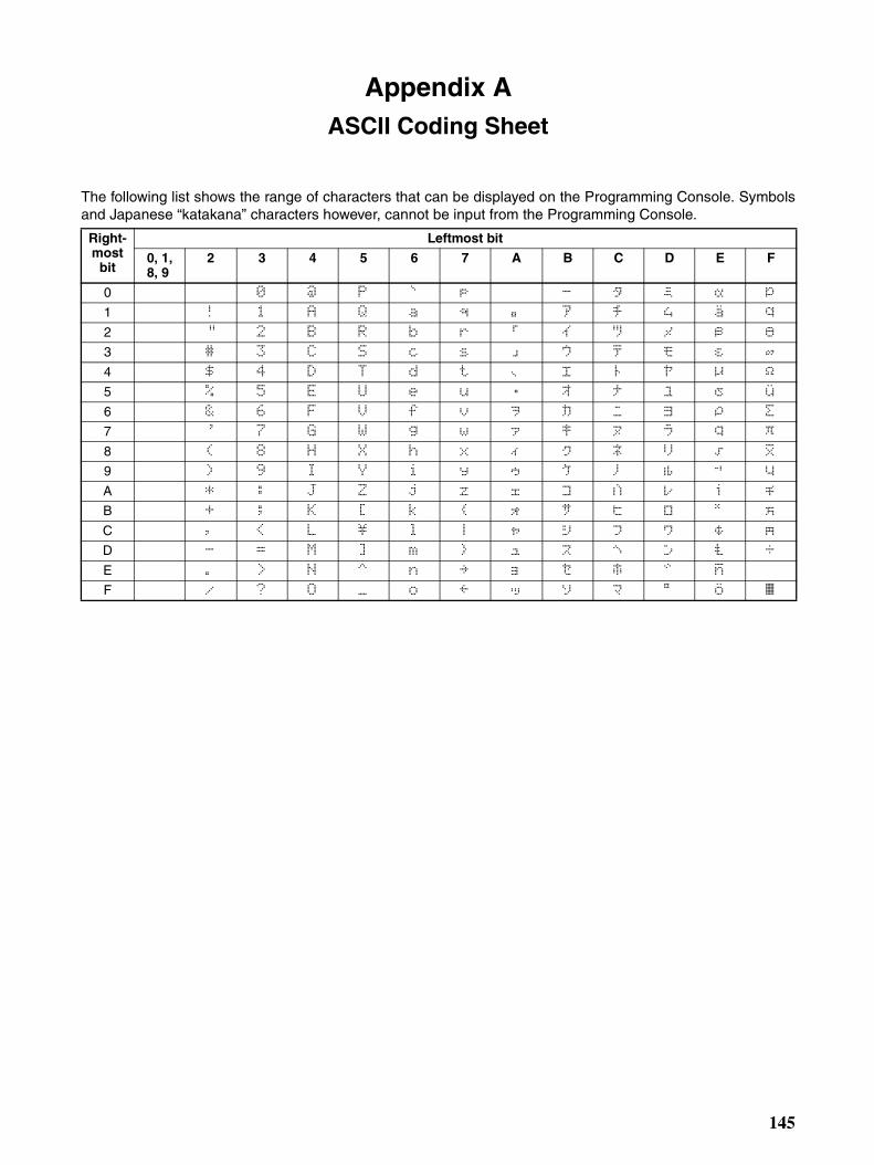
Appendix AASCII Coding Sheet
The following list shows the range of characters that can be displayed on the Programming Console. Symbolsand Japanese “katakana” characters however, cannot be input from the Programming Console.
Right-most
bit
Leftmost bit
0, 1, 8, 9
2 3 4 5 6 7 A B C D E F
0 0 @ P ` p 0 @ P ` p
1 ! 1 A Q a q ! 1 A Q a q
2 ” 2 B R b r " 2 B R b r
3 # 3 C S c s # 3 C S c s
4 $ 4 D T d t $ 4 D T d t
5 % 5 E U e u % 5 E U e u
6 & 6 F V f v & 6 F V f v
7 ’ 7 G W g w ' 7 G W g w
8 ( 8 H X h x ( 8 H X h x
9 ) 9 I Y i y ) 9 I Y i y
A * : J Z j z * : J Z j z
B + ; K [ k + ; K [ k
C , < L \ l | , < L \ l |
D - = M ] m - = M ] m
E . > N ^ n ~ . > N ^ n
F / ? O _ o « / ? O _ o ~
145

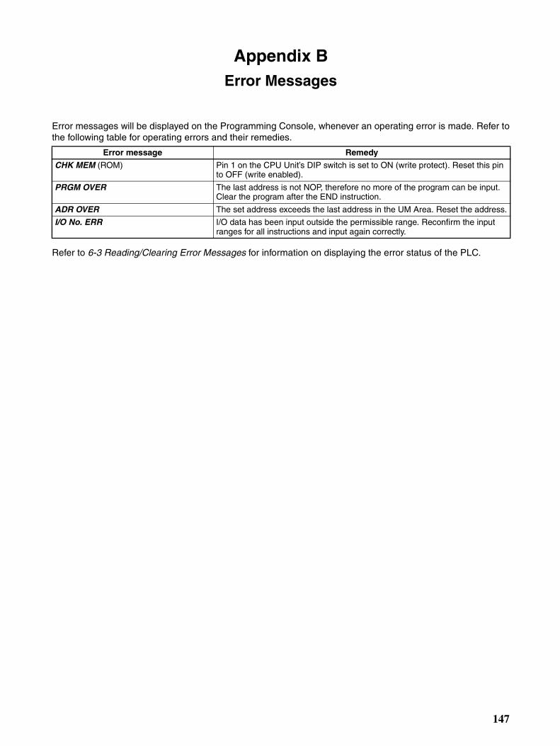
Appendix BError Messages
Error messages will be displayed on the Programming Console, whenever an operating error is made. Refer tothe following table for operating errors and their remedies.
Refer to 6-3 Reading/Clearing Error Messages for information on displaying the error status of the PLC.
Error message Remedy
CHK MEM (ROM) Pin 1 on the CPU Unit’s DIP switch is set to ON (write protect). Reset this pin to OFF (write enabled).
PRGM OVER The last address is not NOP, therefore no more of the program can be input. Clear the program after the END instruction.
ADR OVER The set address exceeds the last address in the UM Area. Reset the address.
I/O No. ERR I/O data has been input outside the permissible range. Reconfirm the input ranges for all instructions and input again correctly.
147

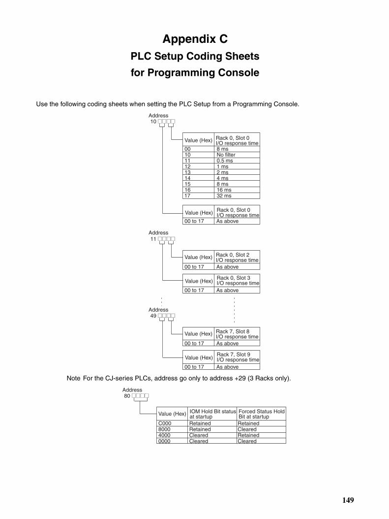
Appendix CPLC Setup Coding Sheets
for Programming Console
Use the following coding sheets when setting the PLC Setup from a Programming Console.
Note For the CJ-series PLCs, address go only to address +29 (3 Racks only).
Address10 @@@@
Value (Hex) Rack 0, Slot 0I/O response time
Rack 0, Slot 0I/O response timeValue (Hex)
As above00 to 17
001011121314151617
8 msNo filter0.5 ms1 ms2 ms4 ms8 ms16 ms32 ms
Address
Address
11 @@@@
Value (Hex) Rack 0, Slot 2I/O response time
Rack 0, Slot 3I/O response timeValue (Hex)
As above00 to 17
49 @@@@
As above00 to 17
Value (Hex) Rack 7, Slot 8I/O response time
Rack 7, Slot 9I/O response timeValue (Hex)
As above00 to 17
As above00 to 17
IOM Hold Bit status at startup
Forced Status Hold Bit at startup
RetainedRetainedClearedCleared
RetainedClearedRetainedCleared
Address80 @@@@
Value (Hex)
C000800040000000
149
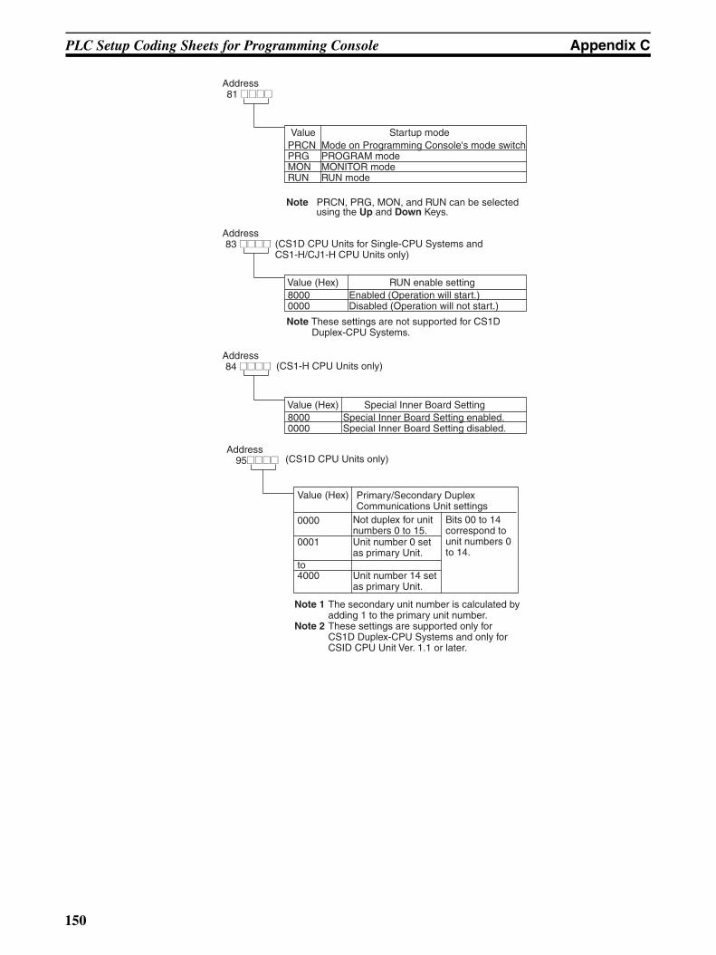
PLC Setup Coding Sheets for Programming Console Appendix C
Mode on Programming Console's mode switchPROGRAM modeMONITOR modeRUN mode
PRCNPRGMONRUN
Startup mode
Note PRCN, PRG, MON, and RUN can be selected using the Up and Down Keys.
Address81 @@@@
Value
Enabled (Operation will start.)Disabled (Operation will not start.)
80000000
RUN enable setting
Address83 @@@@
Value (Hex)
(CS1D CPU Units for Single-CPU Systems and CS1-H/CJ1-H CPU Units only)
Note These settings are not supported for CS1D Duplex-CPU Systems.
Special Inner Board Setting enabled.Special Inner Board Setting disabled.
80000000
Special Inner Board Setting
Address84 @@@@
Value (Hex)
(CS1-H CPU Units only)
Address95@@@@
Value (Hex)
0000
0001
to4000
(CS1D CPU Units only)
Note 1 The secondary unit number is calculated by adding 1 to the primary unit number.
Note 2 These settings are supported only for CS1D Duplex-CPU Systems and only for CSID CPU Unit Ver. 1.1 or later.
Primary/Secondary Duplex Communications Unit settings
Not duplex for unit numbers 0 to 15.
Bits 00 to 14 correspond to unit numbers 0 to 14.
Unit number 0 set as primary Unit.
Unit number 14 set as primary Unit.
150
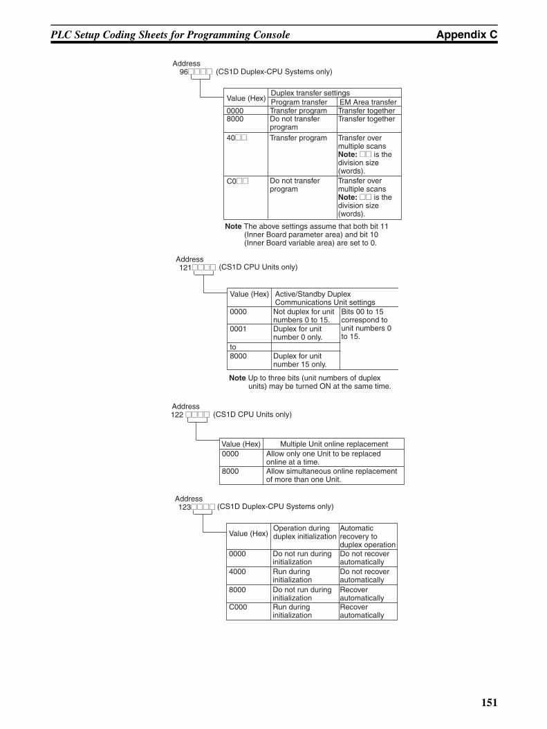
PLC Setup Coding Sheets for Programming Console Appendix C
Program transferDuplex transfer settings
EM Area transferTransfer program
Transfer program
Transfer togetherTransfer together
Address96@@@@
Value (Hex)
00008000
40@@
C0@@
(CS1D Duplex-CPU Systems only)
Do not transfer program
Transfer over multiple scans Note: @@ is the division size (words).
Do not transfer program
Transfer over multiple scans Note: @@ is the division size (words).
Note The above settings assume that both bit 11 (Inner Board parameter area) and bit 10 (Inner Board variable area) are set to 0.
Address121@@@@
Value (Hex)
0000
0001
to8000
(CS1D CPU Units only)
Active/Standby Duplex Communications Unit settingsNot duplex for unit numbers 0 to 15.
Bits 00 to 15 correspond to unit numbers 0 to 15.
Duplex for unit number 0 only.
Duplex for unit number 15 only.
Note Up to three bits (unit numbers of duplex units) may be turned ON at the same time.
0000
8000
Multiple Unit online replacement
Address122 @@@@
Value (Hex)
(CS1D CPU Units only)
Allow only one Unit to be replaced online at a time.Allow simultaneous online replacement of more than one Unit.
Address123@@@@
Value (Hex)
0000
4000
8000
C000
(CS1D Duplex-CPU Systems only)
Operation during duplex initialization
Automatic recovery to duplex operation
Do not run during initialization
Do not recover automatically
Run during initialization
Do not recover automatically
Do not run during initialization
Recover automatically
Run during initialization
Recover automatically
151
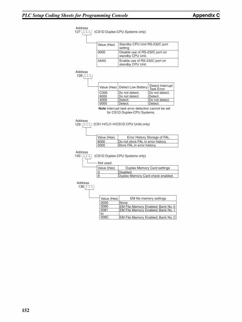
PLC Setup Coding Sheets for Programming Console Appendix C
0000
5AA5
Address127 @@@@
Value (Hex)
(CS1D Duplex-CPU Systems only)
Standby CPU Unit RS-232C port settingDisable use of RS-232C port on standby CPU Unit.
Enable use of RS-232C port on standby CPU Unit.
Detect Low Battery Detect Interrupt Task Error
Do not detect.Do not detect.Detect.Detect.
Do not detect.Detect.Do not detect.Detect.
Address128@@@@
Value (Hex)
C000800040000000
Note Interrupt task error detection cannot be set for CS1D Duplex-CPU Systems.
Do not store FAL in error history.Store FAL in error history.
80000000
Error History Storage of FAL
Address129 @@@@
Value (Hex)
(CS1-H/CJ1-H/CS1D CPU Units only)
Disabled.Duplex Memory Card check enabled.
08
Duplex Memory Card settings
Address130 @@@@
Value (Hex)
(CS1D Duplex-CPU Systems only)
Not used.
EM file memory settingsNoneEM File Memory Enabled: Bank No. 0EM File Memory Enabled: Bank No. 1
EM File Memory Enabled: Bank No. C
Address136@@@@
Value (Hex)000000800081to008C
152
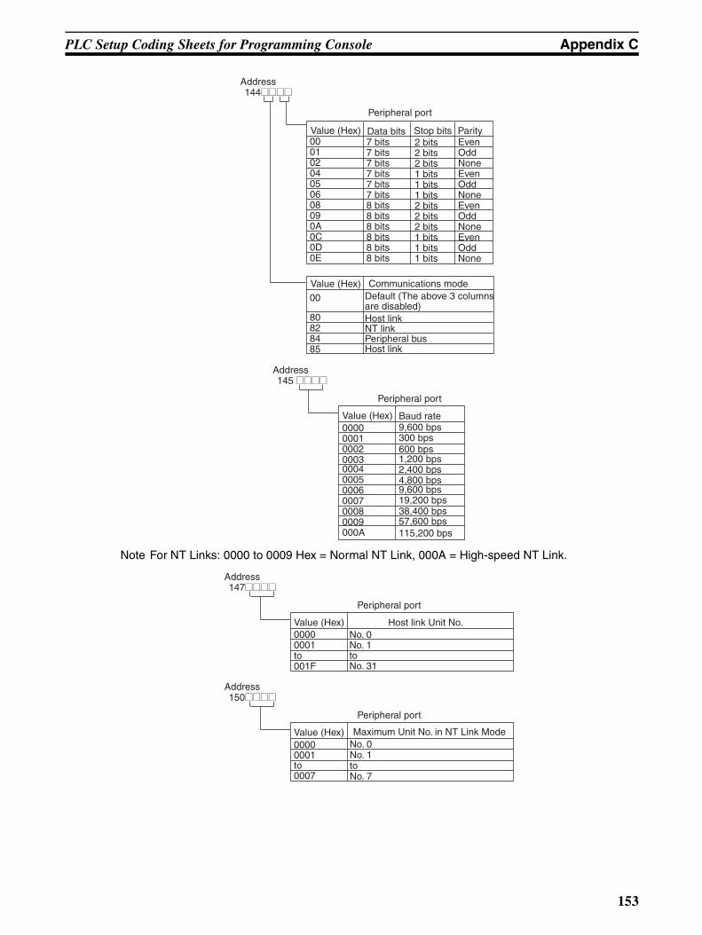
PLC Setup Coding Sheets for Programming Console Appendix C
Note For NT Links: 0000 to 0009 Hex = Normal NT Link, 000A = High-speed NT Link.
Peripheral port
Stop bitsData bits Parity7 bits7 bits7 bits7 bits7 bits7 bits8 bits8 bits8 bits8 bits8 bits8 bits
EvenOddNoneEvenOddNoneEvenOddNoneEvenOddNone
Communications modeDefault (The above 3 columns are disabled)Host linkNT linkPeripheral busHost link
Address144@@@@
Value (Hex)
Value (Hex)00
80828485
00010204050608090A0C0D0E
2 bits2 bits2 bits1 bits1 bits1 bits2 bits2 bits2 bits1 bits1 bits1 bits
Peripheral port
Baud rate9,600 bps300 bps600 bps1,200 bps2,400 bps4,800 bps9,600 bps19,200 bps38,400 bps57,600 bps115,200 bps
Address145 @@@@
Value (Hex)0000000100020003000400050006000700080009000A
Peripheral port
Host link Unit No.No. 0No. 1toNo. 31
Address147@@@@
Value (Hex)00000001to001F
Maximum Unit No. in NT Link Mode
Peripheral port
No. 0No. 1toNo. 7
Address150@@@@
Value (Hex)00000001to0007
153

PLC Setup Coding Sheets for Programming Console Appendix C
Note For NT Links: 0000 to 0009 Hex = Normal NT Link, 000A = High-speed NT Link.
RS-232C Port
EvenOddNoneEvenOddNoneEvenOddNoneEvenOddNone
Default (The above 3 columns are disabled)Host linkNT linkNo-protocolPeripheral busHost link
Stop bitsData bits Parity7 bits7 bits7 bits7 bits7 bits7 bits8 bits8 bits8 bits8 bits8 bits8 bits
Communications mode
Address160@@@@
Value (Hex)
Value (Hex)00
8082838485
00010204050608090A0C0D0E
2 bits2 bits2 bits1 bits1 bits1 bits2 bits2 bits2 bits1 bits1 bits1 bits
RS-232C port
Baud rate9,600 bps300 bps600 bps1,200 bps2,400 bps4,800 bps9,600 bps19,200 bps38,400 bps57,600 bps115,200 bps
Address161@@@@
Value (Hex)0000000100020003000400050006000700080009000A
No-protocol mode delay
RS-232C port
0 ms10 msto99,990 ms
Address162@@@@
Value (Hex)00000001to270F
RS-232C port
Host link Unit No.No. 0
No. 2toNo. 31
Address163@@@@
Value (Hex)0000
0002to001F
No. 10001
154
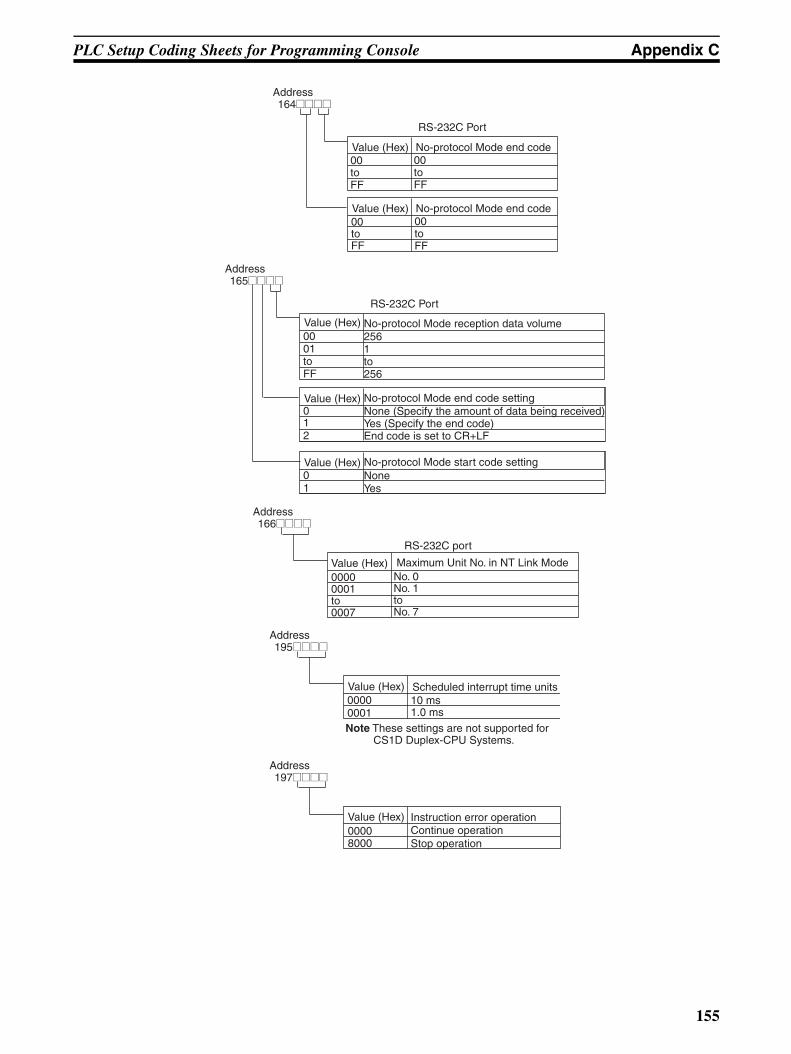
PLC Setup Coding Sheets for Programming Console Appendix C
No-protocol Mode end code
RS-232C Port
00toFF
Address164@@@@
Value (Hex)00toFF
No-protocol Mode end code00toFF
Value (Hex)00toFF
No-protocol Mode reception data volume
No-protocol Mode end code setting
No-protocol Mode start code setting
None (Specify the amount of data being received)Yes (Specify the end code)End code is set to CR+LF
NoneYes
RS-232C Port
2561to256
Address165@@@@
Value (Hex)0001toFF
Value (Hex)012
Value (Hex)01
RS-232C port
Maximum Unit No. in NT Link ModeNo. 0No. 1toNo. 7
Address166@@@@
Value (Hex)00000001to0007
Scheduled interrupt time units10 ms1.0 ms
Address195@@@@
Value (Hex)00000001Note These settings are not supported for
CS1D Duplex-CPU Systems.
Instruction error operationContinue operationStop operation
Address197@@@@
Value (Hex)00008000
155
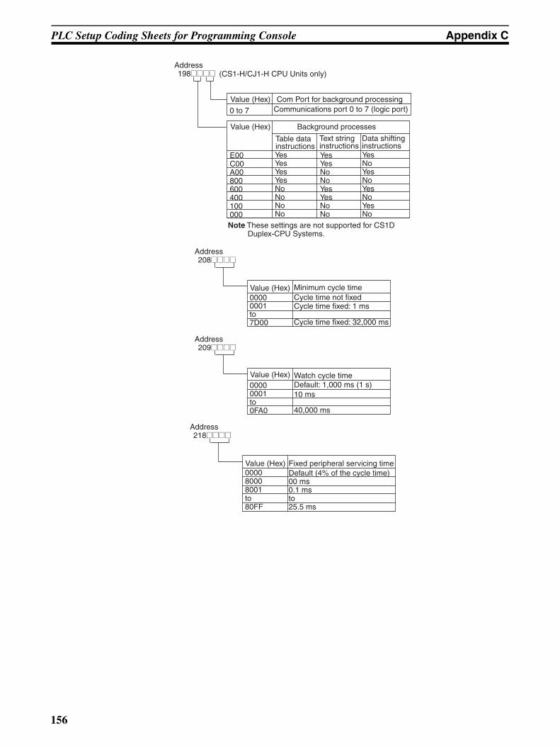
PLC Setup Coding Sheets for Programming Console Appendix C
Text string instructions
Table data instructions
Data shifting instructions
YesYesYesYesNoNoNoNo
YesNoYesNoYesNoYesNo
Com Port for background processingCommunications port 0 to 7 (logic port)
Address198@@@@
Value (Hex)
Value (Hex)0 to 7
E00C00A00800600400100000
YesYesNoNoYesYesNoNo
Background processes
(CS1-H/CJ1-H CPU Units only)
Note These settings are not supported for CS1D Duplex-CPU Systems.
Minimum cycle timeCycle time not fixedCycle time fixed: 1 ms
Cycle time fixed: 32,000 ms
Address208@@@@
Value (Hex)00000001to7D00
Watch cycle timeDefault: 1,000 ms (1 s)10 ms
40,000 ms
Address209@@@@
Value (Hex)00000001to0FA0
Fixed peripheral servicing timeDefault (4% of the cycle time)00 ms0.1 msto25.5 ms
Address218@@@@
Value (Hex)000080008001to80FF
156
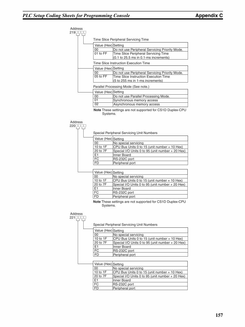
PLC Setup Coding Sheets for Programming Console Appendix C
Setting
SettingDo not use Peripheral Servicing Priority Mode.Time Slice Instruction Execution Time(5 to 255 ms in 1-ms increments)
Time Slice Peripheral Servicing Time
Do not use Peripheral Servicing Priority Mode.Time Slice Peripheral Servicing Time(0.1 to 25.5 ms in 0.1-ms increments)
Address219@@@@
Value (Hex)0001 to FF
Value (Hex)0005 to FF
Time Slice Instruction Execution Time
SettingDo not use Parallel Processing Mode.Synchronous memory access
Value (Hex)
01
Parallel Processing Mode (See note.)
00
Asynchronous memory access02
Note These settings are not supported for CS1D Duplex-CPU Systems.
Setting
Special Peripheral Servicing Unit Numbers
No special servicingCPU Bus Units 0 to 15 (unit number + 10 Hex)Special I/O Units 0 to 95 (unit number + 20 Hex)Inner BoardRS-232C portPeripheral port
Address220@@@@
Value (Hex)0010 to 1F20 to 7FE1FCFD
SettingNo special servicingCPU Bus Units 0 to 15 (unit number + 10 Hex)Special I/O Units 0 to 95 (unit number + 20 Hex)Inner BoardRS-232C portPeripheral port
Value (Hex)0010 to 1F20 to 7FE1FCFD
Note These settings are not supported for CS1D Duplex-CPU Systems.
Setting
Special Peripheral Servicing Unit Numbers
No special servicingCPU Bus Units 0 to 15 (unit number + 10 Hex)Special I/O Units 0 to 95 (unit number + 20 Hex)Inner BoardRS-232C portPeripheral port
Address221@@@@
Value (Hex)0010 to 1F20 to 7FE1FCFD
SettingNo special servicingCPU Bus Units 0 to 15 (unit number + 10 Hex)Special I/O Units 0 to 95 (unit number + 20 Hex)Inner BoardRS-232C portPeripheral port
Value (Hex)0010 to 1F20 to 7FE1FCFD
157
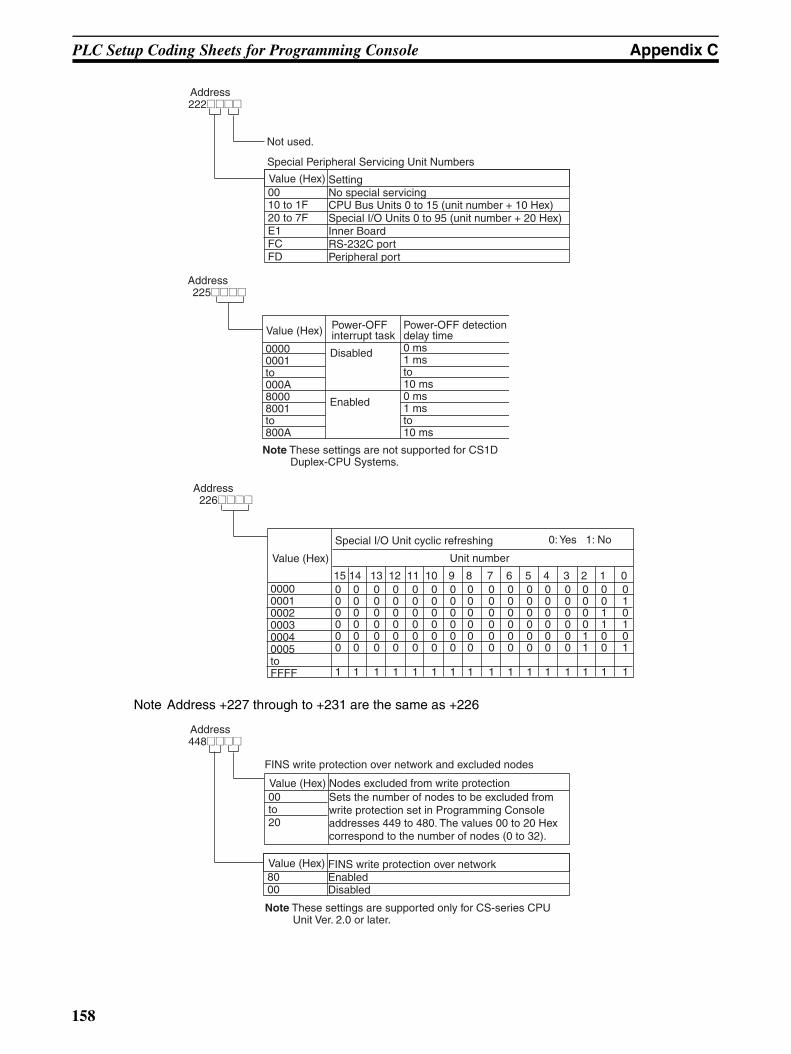
PLC Setup Coding Sheets for Programming Console Appendix C
Note Address +227 through to +231 are the same as +226
Not used.
Special Peripheral Servicing Unit Numbers
Address222@@@@
SettingNo special servicingCPU Bus Units 0 to 15 (unit number + 10 Hex)Special I/O Units 0 to 95 (unit number + 20 Hex)Inner BoardRS-232C portPeripheral port
Value (Hex)0010 to 1F20 to 7FE1FCFD
Power-OFF interrupt task
Power-OFF detection delay time
Disabled
Enabled
0 ms1 msto10 ms
Address225@@@@
Value (Hex)
00000001to000A
0 ms1 msto10 ms
80008001to800A
Note These settings are not supported for CS1D Duplex-CPU Systems.
Special I/O Unit cyclic refreshing 0: Yes 1: No
Unit number
Address226@@@@
Value (Hex)
000000010002000300040005toFFFF
15 14 13 12 11 10 9 8 7 6 5 4 3 2 1 00 0 0 0 0 0 0 0 0 0 0 0 0 0 0 00 0 0 0 0 0 0 0 0 0 0 0 0 0 0 10 0 0 0 0 0 0 0 0 0 0 0 0 0 1 00 0 0 0 0 0 0 0 0 0 0 0 0 0 1 10 0 0 0 0 0 0 0 0 0 0 0 0 1 0 00 0 0 0 0 0 0 0 0 0 0 0 0 1 0 1
1 1 1 1 1 1 1 1 1 1 1 1 1 1 1 1
Nodes excluded from write protection
FINS write protection over network and excluded nodes
Sets the number of nodes to be excluded from write protection set in Programming Console addresses 449 to 480. The values 00 to 20 Hex correspond to the number of nodes (0 to 32).
Address448@@@@
Value (Hex)00to20
FINS write protection over networkEnabled Disabled
Value (Hex)8000
Note These settings are supported only for CS-series CPU Unit Ver. 2.0 or later.
158
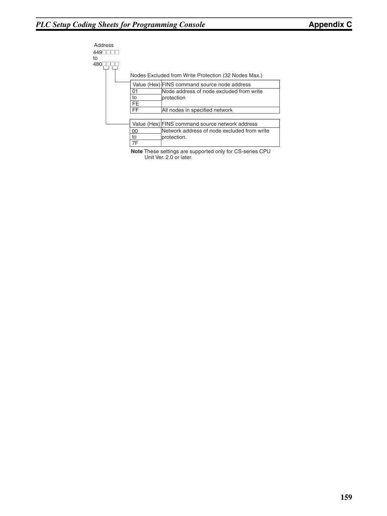
PLC Setup Coding Sheets for Programming Console Appendix C
FINS command source node address
Nodes Excluded from Write Protection (32 Nodes Max.)
Node address of node excluded from write protection
Address
480@@@@
Value (Hex)01toFEFF
00
449@@@@to
All nodes in specified network
FINS command source network addressNetwork address of node excluded from write protection.
Value (Hex)
to7F
Note These settings are supported only for CS-series CPU Unit Ver. 2.0 or later.
159

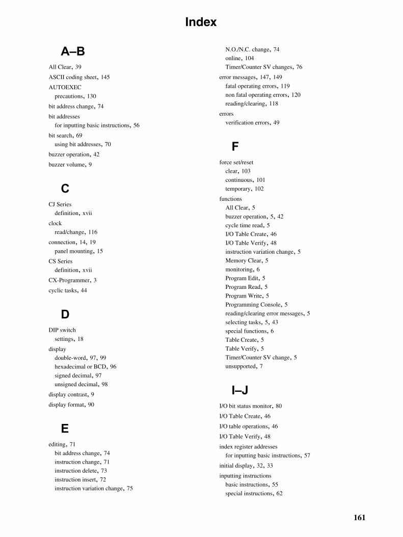
Index
A–BAll Clear, 39
ASCII coding sheet, 145
AUTOEXEC
precautions, 130
bit address change, 74
bit addresses
for inputting basic instructions, 56
bit search, 69
using bit addresses, 70
buzzer operation, 42
buzzer volume, 9
CCJ Series
definition, xvii
clock
read/change, 116
connection, 14, 19
panel mounting, 15
CS Series
definition, xvii
CX-Programmer, 3cyclic tasks, 44
DDIP switch
settings, 18
display
double-word, 97, 99
hexadecimal or BCD, 96
signed decimal, 97
unsigned decimal, 98
display contrast, 9display format, 90
Eediting, 71
bit address change, 74
instruction change, 71
instruction delete, 73
instruction insert, 72
instruction variation change, 75
N.O./N.C. change, 74
online, 104
Timer/Counter SV changes, 76
error messages, 147, 149
fatal operating errors, 119
non fatal operating errors, 120
reading/clearing, 118
errors
verification errors, 49
Fforce set/reset
clear, 103
continuous, 101
temporary, 102
functions
All Clear, 5buzzer operation, 5, 42
cycle time read, 5I/O Table Create, 46
I/O Table Verify, 48
instruction variation change, 5Memory Clear, 5monitoring, 6Program Edit, 5Program Read, 5Program Write, 5Programming Console, 5reading/clearing error messages, 5selecting tasks, 5, 43
special functions, 6Table Create, 5Table Verify, 5Timer/Counter SV change, 5unsupported, 7
I–JI/O bit status monitor, 80
I/O Table Create, 46
I/O table operations, 46
I/O Table Verify, 48
index register addresses
for inputting basic instructions, 57
initial display, 32, 33
inputting instructions
basic instructions, 55
special instructions, 62
161
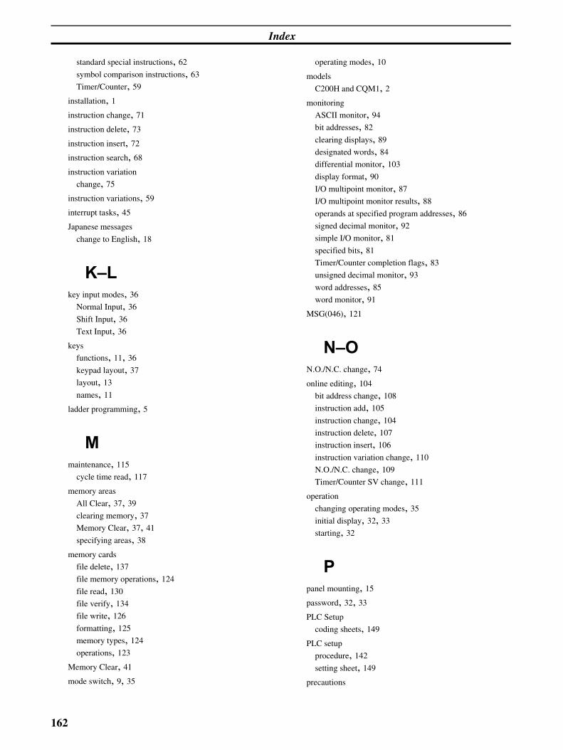
Index
standard special instructions, 62
symbol comparison instructions, 63
Timer/Counter, 59
installation, 1instruction change, 71
instruction delete, 73
instruction insert, 72
instruction search, 68
instruction variation
change, 75
instruction variations, 59
interrupt tasks, 45
Japanese messages
change to English, 18
K–Lkey input modes, 36
Normal Input, 36
Shift Input, 36
Text Input, 36
keys
functions, 11, 36
keypad layout, 37
layout, 13
names, 11
ladder programming, 5
Mmaintenance, 115
cycle time read, 117
memory areas
All Clear, 37, 39
clearing memory, 37
Memory Clear, 37, 41
specifying areas, 38
memory cards
file delete, 137
file memory operations, 124
file read, 130
file verify, 134
file write, 126
formatting, 125
memory types, 124
operations, 123
Memory Clear, 41
mode switch, 9, 35
operating modes, 10
models
C200H and CQM1, 2monitoring
ASCII monitor, 94
bit addresses, 82
clearing displays, 89
designated words, 84
differential monitor, 103
display format, 90
I/O multipoint monitor, 87
I/O multipoint monitor results, 88
operands at specified program addresses, 86
signed decimal monitor, 92
simple I/O monitor, 81
specified bits, 81
Timer/Counter completion flags, 83
unsigned decimal monitor, 93
word addresses, 85
word monitor, 91
MSG(046), 121
N–ON.O./N.C. change, 74
online editing, 104
bit address change, 108
instruction add, 105
instruction change, 104
instruction delete, 107
instruction insert, 106
instruction variation change, 110
N.O./N.C. change, 109
Timer/Counter SV change, 111
operation
changing operating modes, 35
initial display, 32, 33
starting, 32
Ppanel mounting, 15
password, 32, 33
PLC Setup
coding sheets, 149
PLC setup
procedure, 142
setting sheet, 149
precautions
162
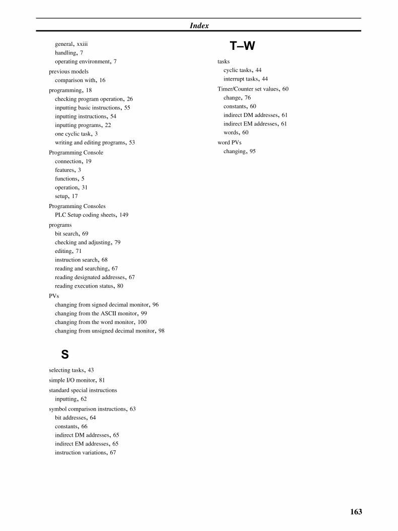
Index
general, xxiii
handling, 7operating environment, 7
previous models
comparison with, 16
programming, 18
checking program operation, 26
inputting basic instructions, 55
inputting instructions, 54
inputting programs, 22
one cyclic task, 3writing and editing programs, 53
Programming Console
connection, 19
features, 3functions, 5operation, 31
setup, 17
Programming Consoles
PLC Setup coding sheets, 149
programs
bit search, 69
checking and adjusting, 79
editing, 71
instruction search, 68
reading and searching, 67
reading designated addresses, 67
reading execution status, 80
PVs
changing from signed decimal monitor, 96
changing from the ASCII monitor, 99
changing from the word monitor, 100
changing from unsigned decimal monitor, 98
Sselecting tasks, 43
simple I/O monitor, 81
standard special instructions
inputting, 62
symbol comparison instructions, 63
bit addresses, 64
constants, 66
indirect DM addresses, 65
indirect EM addresses, 65
instruction variations, 67
T–Wtasks
cyclic tasks, 44
interrupt tasks, 44
Timer/Counter set values, 60
change, 76
constants, 60
indirect DM addresses, 61
indirect EM addresses, 61
words, 60
word PVs
changing, 95
163


165
Revision History
A manual revision code appears as a suffix to the catalog number on the front cover of the manual.
The following table outlines the changes made to the manual during each revision. Page numbers refer to theprevious version.
Revision code Date Revised content
01 March 1999 Original production
02 May 2001 Information on CJ-series PCs, the CQM1H-PRO01-E Programming Console, and PLC Setup addresses 219 to 222 added.
03 September 2001 Information on new CPU Units.Page ix: Addition to introduction at top of page and model numbers added to manual names.Page 2: Model numbers added to bottom table and information added after table.Pages 9, 15, 18, 20, 32 to 36, and 42: “CS Series” changed to “CS1” and “CJ Series” changed to “CJ1/CJ1-H/CS1-H.”Page 46: Note added toward top of page and section and note added to bottom.Pages 138 to 145: Deleted.Pages 148 to 154: Moved to Appendix C.Pages 148, 150, and 151: Note added.Pages 149 and 152: Information for new addresses added.Page 151: Information for following addresses moved to correct order: 163, 166.
04 November 2003 The abbreviation for Programmable Logic Controller was changed from PC to PLC throughout the manual. Information on CS1D Duplex-CPU Systems and CPU Units for Duplex-CPU Systems was added, including the following changes.Page ix: Changed introduction at top of page, added model numbers to manual names, and added extra manuals.Page 2: Changed information on applicable CPU Units.Page 8: Changed diagrams to show Key Sheets in English.Pages 145 to 152: Removed “+” symbol from all addresses, added new address settings, and added notes indicating whether settings are supported in Duplex-CPU Systems.
05 October 2005 Page v: Information on general precautions notation added.Page xix: Information on liability and warranty added.
Cat. No. W341-E-05
Revision code

OMRON CorporationControl Devices Division H.Q.Shiokoji Horikawa, Shimogyo-ku,Kyoto, 600-8530 JapanTel: (81)75-344-7109/Fax: (81)75-344-7149
Regional Headquarters
OMRON EUROPE B.V.Wegalaan 67-69, NL-2132 JD HoofddorpThe NetherlandsTel: (31)2356-81-300/Fax: (31)2356-81-388
OMRON ELECTRONICS LLC1 East Commerce Drive, Schaumburg, IL 60173U.S.A.Tel: (1)847-843-7900/Fax: (1)847-843-8568
OMRON ASIA PACIFIC PTE. LTD.83 Clemenceau Avenue, #11-01, UE Square,Singapore 239920Tel: (65)6835-3011/Fax: (65)6835-2711
OMRON (CHINA) CO., LTD.Room 2211, Bank of China Tower, 200 Yin Cheng Zhong Road,PuDong New Area, Shanghai, 200120 ChinaTel: (86)21-5037-2222/Fax: (86)21-5037-2200

Cat. No.
This ma
Authorized Distributor:
W341-E1-05 Note: Specifications subject to change without notice Printed in Japan
nual is printed on 100% recycled paper.