cranes manual vinca ver 01-10 en
TRANSCRIPT

RReeff..:: 1188 -- CCrraanneess
EEddiittiioonn 0011//1100
GENERAL INSTRUCTION MANUAL
BRIDGE CRANE – GANTRY CRANE
VINCA EQUIPOS INDUSTRIALES, S.A. Pol. Ind. Torre Bovera – C/ Técnica 39
08740 SANT ANDREU DE LA BARCA (BARCELONA) SPAIN Telf.: +34 936 356 120 / Fax.: +34 936 356 130
www.vinca.es
RReeff..:: 1188 -- CCrraanneess
EEddiittiioonn 0011//1100
1
INDEX
0 PRELIMINARY ........................................ .........................................................................2 0.1 Symbols and abbreviations ...........................................................................................2
1 DESCRIPTION OF THE CRANE ......................................................................................3 1.1. Identification VINCA Cranes components.......................................................................3 1.2. Identification VINCA Gantry Cranes components ...........................................................4
2 GENERAL SAFETY INSTRUCTIONS ........................ ......................................................5 2.1. Crane classification according its service conditions ......................................................5
2.1.1 Load spectrum ...................................................................................................5 2.1.2 Average daily operating time..............................................................................5 2.1.3 Determining the operating group........................................................................6 2.1.4 Duty factor .........................................................................................................6
2.2. Safety operating instruction VINCA lifting equipments....................................................7 2.3. Warnings........................................................................................................................7 2.4. Labelling and Inscriptions ...............................................................................................9
3 CRANE INSTALLATION ................................. ...............................................................11 3.1. Prior the installation......................................................................................................11 3.2. Lifting equipment positioning ........................................................................................11 3.3. Electrical connection of VINCA’s equipments ...............................................................15
3.3.1. Prior the installation .........................................................................................15 3.3.2. VINCA’s lifting equipment connection. .............................................................15 3.3.3. Overload protection..........................................................................................16
After lifting equipment connection .......................................................................................17 3.5. Storage ........................................................................................................................17 3.6. Equipment dismantling .................................................................................................18 3.7. Demolition ....................................................................................................................18
4 OPERATING MODE .......................................................................................................19 4.1. Prior the start up...........................................................................................................19 4.2. Start up and operation..................................................................................................19 4.3. Using the pushbutton controller. ...................................................................................20 4.4 Stopping the equipment. ...............................................................................................20
5. MAINTENANCE........................................ ......................................................................21 5.1. Safety instructions........................................................................................................21 5.2. Preventive Maintenance Program ................................................................................21
5.2.1. Bridge Crane / Gantry Crane Maintenance............................................................21 5.2.2. Hoist Maintenance ...........................................................................................23
5.3. Travelling reducers......................................................................................................25 5.4. Travelling brakes regulation ........................................................................................25
5.5.1 Servicing frequency ................................................................................................26 5.5.2 Points to be checked during examinations..............................................................26 5.5.3 Replacement criteria...............................................................................................26
5.6. Inspection calendar ......................................................................................................26 5.7. Troubleshooting ...........................................................................................................27
6. APPENDIX......................................................................................................................28 MAINTENANCE AND BREAKDOWNS HISTORICAL RECORD.........................................29
RReeff..:: 1188 -- CCrraanneess
EEddiittiioonn 0011//1100
2
0 PRELIMINARY The necessary instructions for the installation, use and maintenance of the crane are included with the crane delivery. Make sure all the necessary documentation is available, specially the HOIST MANUAL. ATENTION: Read carefully all the instructions before using the equipment. A misunderstanding can cause several damages to other people and to the crane. For an easier later request, sep the manuals in a safe place to all the staff who uses the crane and do the maintenance. 0.1 Symbols and abbreviations In the present manual the following symbols are used:
� Attention!
� Warning
� Danger!
RReeff..:: 1188 -- CCrraanneess
EEddiittiioonn 0011//1100
3
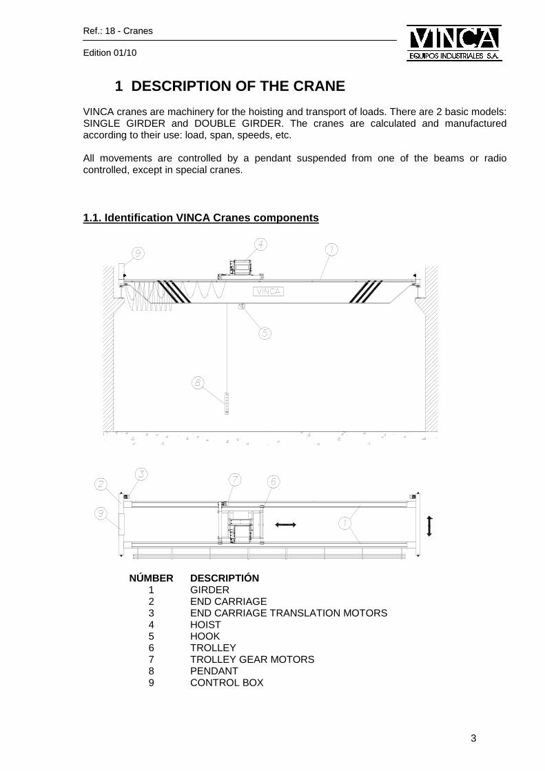
1 DESCRIPTION OF THE CRANE VINCA cranes are machinery for the hoisting and transport of loads. There are 2 basic models: SINGLE GIRDER and DOUBLE GIRDER. The cranes are calculated and manufactured according to their use: load, span, speeds, etc. All movements are controlled by a pendant suspended from one of the beams or radio controlled, except in special cranes. 1.1. Identification VINCA Cranes components
NÚMBER DESCRIPTIÓN 1 GIRDER 2 END CARRIAGE 3 END CARRIAGE TRANSLATION MOTORS 4 HOIST 5 HOOK 6 TROLLEY 7 TROLLEY GEAR MOTORS 8 PENDANT 9 CONTROL BOX
RReeff..:: 1188 -- CCrraanneess
EEddiittiioonn 0011//1100
4
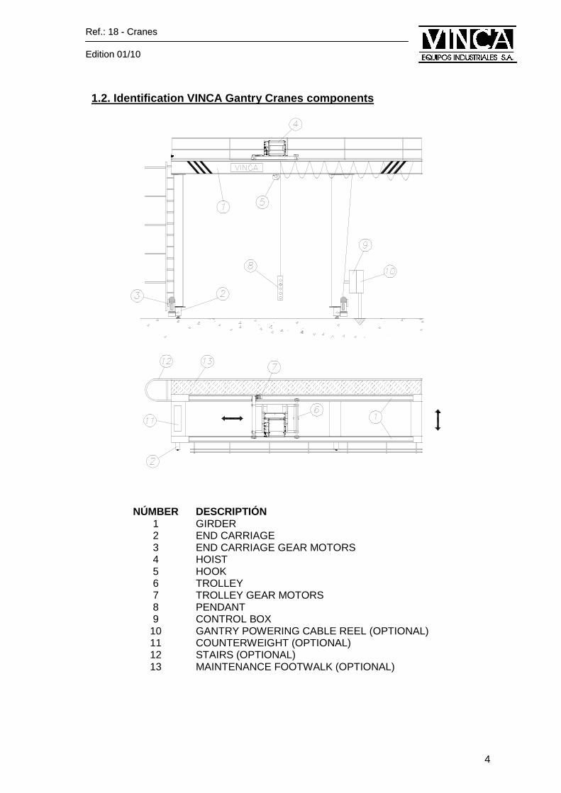
1.2. Identification VINCA Gantry Cranes components
NÚMBER DESCRIPTIÓN 1 GIRDER 2 END CARRIAGE 3 END CARRIAGE GEAR MOTORS 4 HOIST 5 HOOK 6 TROLLEY 7 TROLLEY GEAR MOTORS
8 PENDANT 9 CONTROL BOX
10 GANTRY POWERING CABLE REEL (OPTIONAL) 11 COUNTERWEIGHT (OPTIONAL) 12 STAIRS (OPTIONAL) 13 MAINTENANCE FOOTWALK (OPTIONAL)
RReeff..:: 1188 -- CCrraanneess
EEddiittiioonn 0011//1100
5
2 GENERAL SAFETY INSTRUCTIONS 2.1. Crane classification according its service con ditions For a correct, an effective and safe operation of the lifting and transport equipment the correct classification adapted for each type of application must be chosen. According to FEM 9511 standard the classification depends on the following factors:
� Load spectrum � Average operation time for a working day
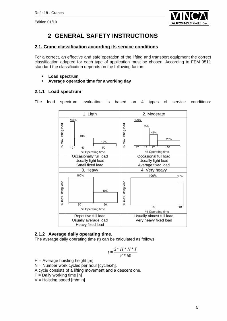
2.1.1 Load spectrum The load spectrum evaluation is based on 4 types of service conditions:
2.1.2 Average daily operating time. The average daily operating time (t) can be calculated as follows:
60
2
∗∗∗∗=
V
TNHt
H = Average hoisting height [m] N = Number work cycles per hour [cycles/h]. A cycle consists of a lifting movement and a descent one. T = Daily working time [h] V = Hoisting speed [m/min]
1. Ligth 2. Moderate
% m
ax. l
iftin
g lo
ad
% Operating time
% m
ax. l
iftin
g lo
ad
% Operating time
Occasionally full load Usually light load Small fixed load
Occasional full load Usually light load
Average fixed load 3. Heavy 4. Very heavy
% m
ax. l
iftin
g lo
ad
% Operating time
% m
ax. l
iftin
g lo
ad
% Operating time
Repetitive full load Usually average load
Heavy fixed load
Usually almost full load Very heavy fixed load
RReeff..:: 1188 -- CCrraanneess
EEddiittiioonn 0011//1100
6
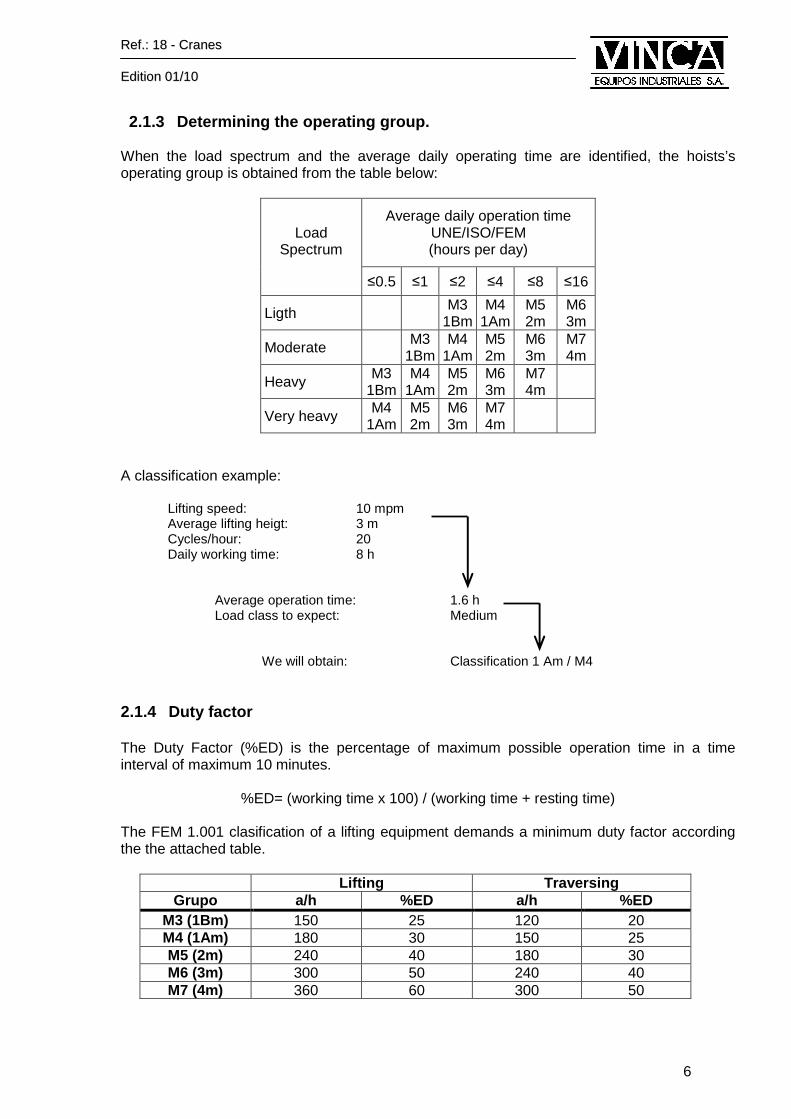
2.1.3 Determining the operating group. When the load spectrum and the average daily operating time are identified, the hoists’s operating group is obtained from the table below:
Load
Spectrum
Average daily operation time UNE/ISO/FEM (hours per day)
≤0.5 ≤1 ≤2 ≤4 ≤8 ≤16
Ligth M3 1Bm
M4 1Am
M5 2m
M6 3m
Moderate M3 1Bm
M4 1Am
M5 2m
M6 3m
M7 4m
Heavy M3 1Bm
M4 1Am
M5 2m
M6 3m
M7 4m
Very heavy M4 1Am
M5 2m
M6 3m
M7 4m
A classification example:
Lifting speed: 10 mpm Average lifting heigt: 3 m Cycles/hour: 20 Daily working time: 8 h
Average operation time: 1.6 h Load class to expect: Medium We will obtain: Classification 1 Am / M4 2.1.4 Duty factor The Duty Factor (%ED) is the percentage of maximum possible operation time in a time interval of maximum 10 minutes.
%ED= (working time x 100) / (working time + resting time) The FEM 1.001 clasification of a lifting equipment demands a minimum duty factor according the the attached table.
Lifting Traversing
Grupo a/h %ED a/h %ED M3 (1Bm) 150 25 120 20 M4 (1Am) 180 30 150 25 M5 (2m) 240 40 180 30 M6 (3m) 300 50 240 40 M7 (4m) 360 60 300 50
RReeff..:: 1188 -- CCrraanneess
EEddiittiioonn 0011//1100
7
2.2. Safety operating instruction VINCA lifting equ ipments The owner of this VINCA Bridge Crane or Gantry Crane is the responsible to fulfil with all the requirements described in these instructions, excluding those for which it has been accorded that the manufacturer will carry out the necessary procedures. The owner should train and instruct operators in the safe use of VINCA lifting equipment. This manual should be in an accessible place to the personal in charge of operation and maintenance. The operator, serviceman and work manager for the lifting equipment should be familiar with the safe working principles for the hoist. The user will have to consider the following norms and prescriptions regarding the construction, manufacture and use of VINCA lifting equipment:
� Low tension installation Regulations (400 V or less). � Environmental Health and Safety Regulations. � FEM Regulations. � CE Machinery Safety Regulations.
� It is essential for the safety of people and proper ty that the crane operator, the crane serviceman and the personnel in charge of cra ne operation and servicing are familiar with and comply with the safe working principles described in the instructions
The protective equipment must always be at user’s and maintenance personnel reach. The owner must also ensure that personnel are adequately trained, that they follow safe working methods and that they use foresight in all stages of the work. 2.3. Warnings
� The use of this lifting equipment for any work different from the described is strictly
forbidden. � Only specifically authorized personnel by the company management will use this lifting
equipment and after having received the corresponding training according to UNE 58-140-94 regulations and precise instructions.
� Read all the instructions supplied with the equipment. The hoist operator must be familiarized with all the instructions and must follow them. At the same time, the hoist operator must be competent for this task, must know all the equipment controls and be able to use them correctly and safety.
� The hoist operator must know also the lifting equipment operation and be aware of any risk of accident in the work location.
� Learn how to operate the hoist in safe conditions before starting to work. Learn also how to control the movements of the hook and load. Use the Hoist Owner’s Manual to familiarize yourself with the hoist and hoist controls.
� Learn the hand signals for hoisting motion, trolley traversing and crane travel. The hoist operator should only accept hand signals from an authorized person.
� Be sure that there is adequate lighting as well as proper tools and equipment for the working site, and that appropriate working procedures are established.
� The lifting equipment operator is the person in charge of it, for this reason he will have to daily review the elements subjected to an stress, as well as the brakes and safety limit switches correct operation, mainly the lifting mechanism ones.
� Do not lift people on the hook or load. � Do no lift a load that is heavier than the maximum permissible load for the hoist or lifting
accessories.
RReeff..:: 1188 -- CCrraanneess
EEddiittiioonn 0011//1100
8
� Do not pull a load from the side. Lower the load with the ropes perpendicular. � Do not lift a load that is fastened to its base.
� Do not go under the hook or load. Do not move the hook or load over a person. A load must never be lifted in a way that can injure a person if the load drops.
� Do not leave a suspended load unattended. � Avoid short, jerky motions. Unnecessary short starts cause the hoisting motor to overheat
quickly. � Start and stop the traveling motion at low speed to prevent the load from swinging
excessively. � Avoid swinging the hook or load during travel motion. � Do not operate the hoists if you know that medication, an illness, injury or other such
handicap impairs you alertness or working ability. � Avoid any manipulation that may question the working area safety. � Stop operating the hoist if it operates abnormally. � If the hoist is not in use, stop it by pressing the emergency stop button.
� NEVER POSITION YOURSELF UNDER THE LOAD.
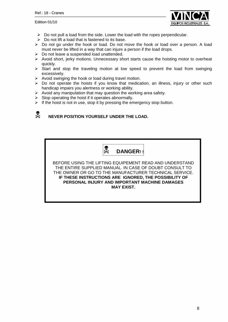
� DANGER! !
BEFORE USING THE LIFTING EQUIPEMENT READ AND UNDERSTAND THE ENTIRE SUPPLIED MANUAL. IN CASE OF DOUBT CONSULT TO
THE OWNER OR GO TO THE MANUFACTURER TECHNICAL SERVICE. IF THESE INSTRUCTIONS ARE IGNORED, THE POSSIBILITY OF
PERSONAL INJURY AND IMPORTANT MACHINE DAMAGES MAY EXIST.
RReeff..:: 1188 -- CCrraanneess
EEddiittiioonn 0011//1100
9
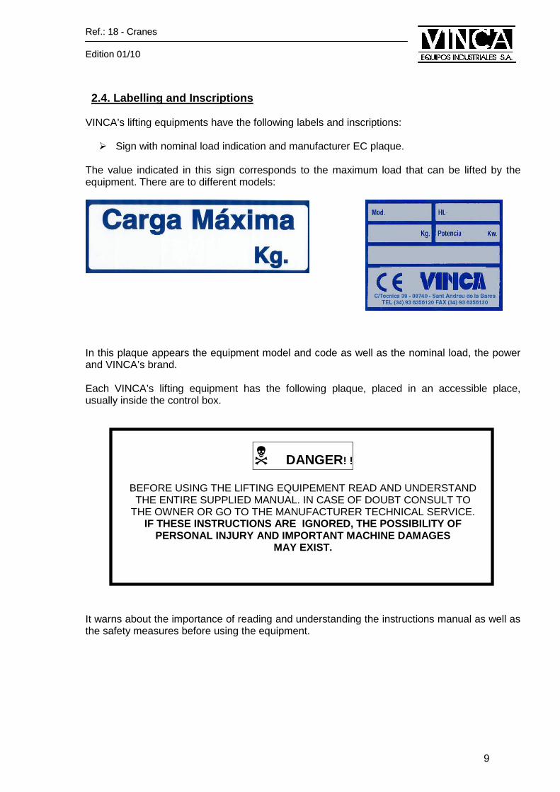
2.4. Labelling and Inscriptions
VINCA’s lifting equipments have the following labels and inscriptions:
� Sign with nominal load indication and manufacturer EC plaque. The value indicated in this sign corresponds to the maximum load that can be lifted by the equipment. There are to different models:
In this plaque appears the equipment model and code as well as the nominal load, the power and VINCA’s brand. Each VINCA’s lifting equipment has the following plaque, placed in an accessible place, usually inside the control box.
� DANGER! !
BEFORE USING THE LIFTING EQUIPEMENT READ AND UNDERSTAND THE ENTIRE SUPPLIED MANUAL. IN CASE OF DOUBT CONSULT TO
THE OWNER OR GO TO THE MANUFACTURER TECHNICAL SERVICE. IF THESE INSTRUCTIONS ARE IGNORED, THE POSSIBILITY OF
PERSONAL INJURY AND IMPORTANT MACHINE DAMAGES MAY EXIST.
It warns about the importance of reading and understanding the instructions manual as well as the safety measures before using the equipment.
RReeff..:: 1188 -- CCrraanneess
EEddiittiioonn 0011//1100
10
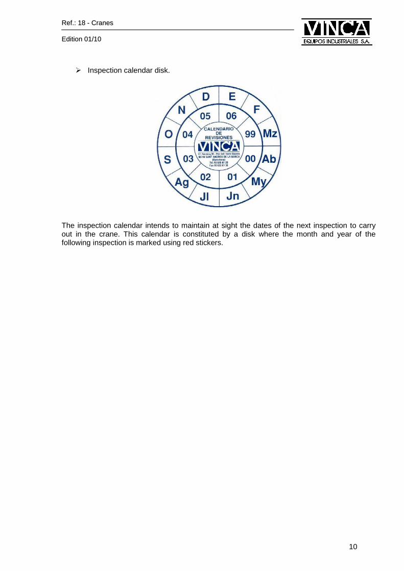
� Inspection calendar disk.
The inspection calendar intends to maintain at sight the dates of the next inspection to carry out in the crane. This calendar is constituted by a disk where the month and year of the following inspection is marked using red stickers.
RReeff..:: 1188 -- CCrraanneess
EEddiittiioonn 0011//1100
11
3 CRANE INSTALLATION 3.1. Prior the installation
� Before starting any lifting equipment installation post warnings and barricades at this working area. It is important to warn that exceptional works are carrying out and they can cause injuries to unauthorized people.
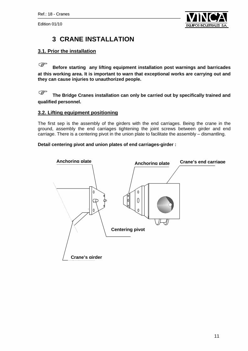
� The Bridge Cranes installation can only be carried out by specifically trained and qualified personnel. 3.2. Lifting equipment positioning The first sep is the assembly of the girders with the end carriages. Being the crane in the ground, assembly the end carriages tightening the joint screws between girder and end carriage. There is a centering pivot in the union plate to facilitate the assembly – dismantling. Detail centering pivot and union plates of end carr iages-girder :
Centering pivot
Anchoring plate Anchoring plate Crane’s end carriage
Crane’s girder
RReeff..:: 1188 -- CCrraanneess
EEddiittiioonn 0011//1100
12
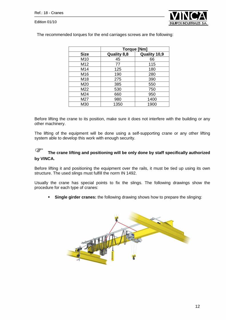
The recommended torques for the end carriages screws are the following:
Torque [Nm]
Size Quality 8,8 Quality 10,9 M10 45 66 M12 77 115 M14 125 180 M16 190 280 M18 275 390 M20 385 550 M22 530 750 M24 660 950 M27 980 1400 M30 1350 1900
Before lifting the crane to its position, make sure it does not interfere with the building or any other machinery. The lifting of the equipment will be done using a self-supporting crane or any other lifting system able to develop this work with enough security.
� The crane lifting and positioning will be only done by staff specifically authorized by VINCA. Before lifting it and positioning the equipment over the rails, it must be tied up using its own structure. The used slings must fulfill the norm IN 1492. Usually the crane has special points to fix the slings. The following drawings show the procedure for each type of cranes:
� Single girder cranes: the following drawing shows how to prepare the slinging:
RReeff..:: 1188 -- CCrraanneess
EEddiittiioonn 0011//1100
13
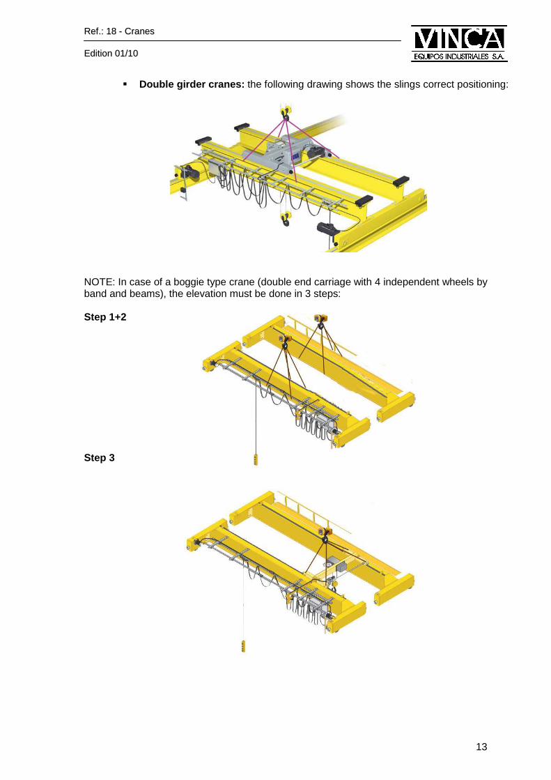
� Double girder cranes: the following drawing shows the slings correct positioning:
NOTE: In case of a boggie type crane (double end carriage with 4 independent wheels by band and beams), the elevation must be done in 3 steps: Step 1+2 Step 3
RReeff..:: 1188 -- CCrraanneess
EEddiittiioonn 0011//1100
14
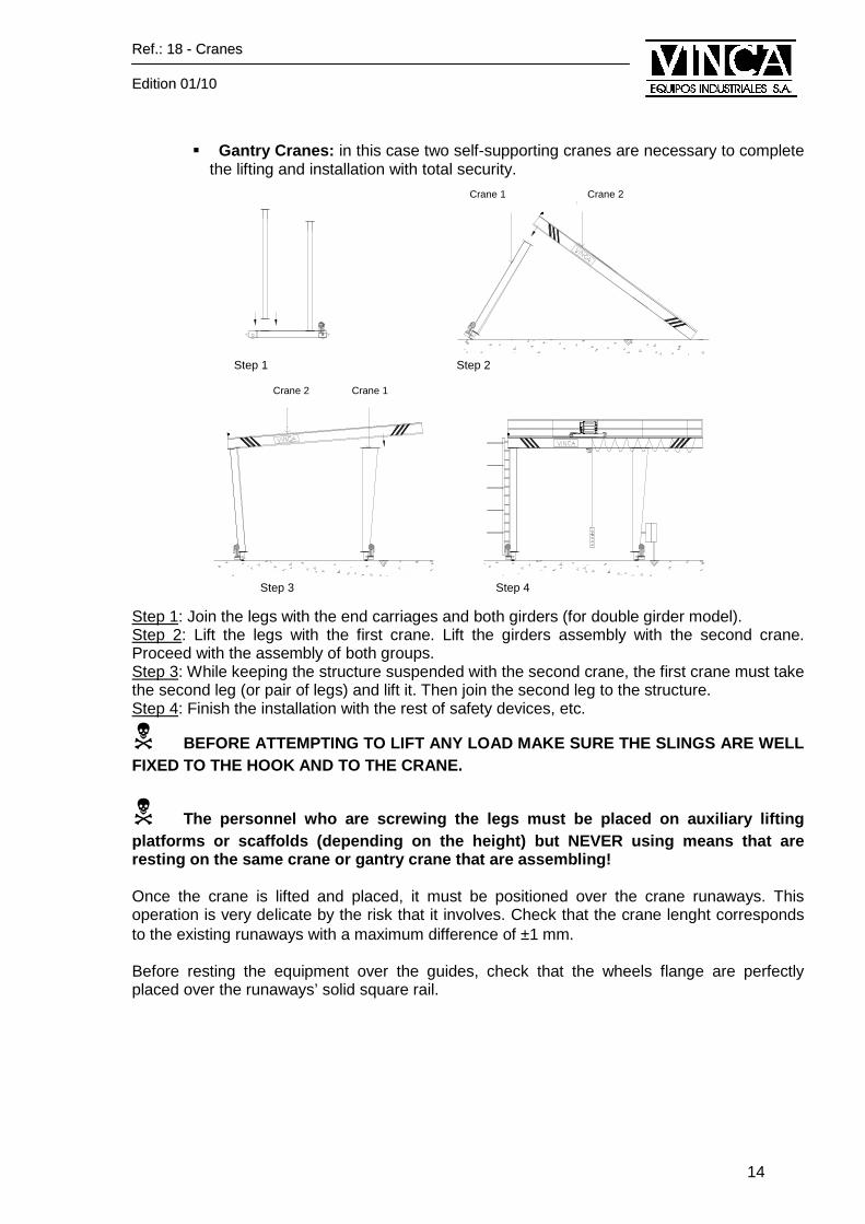
� Gantry Cranes: in this case two self-supporting cranes are necessary to complete
the lifting and installation with total security.
Step 1: Join the legs with the end carriages and both girders (for double girder model). Step 2: Lift the legs with the first crane. Lift the girders assembly with the second crane. Proceed with the assembly of both groups. Step 3: While keeping the structure suspended with the second crane, the first crane must take the second leg (or pair of legs) and lift it. Then join the second leg to the structure. Step 4: Finish the installation with the rest of safety devices, etc.
� BEFORE ATTEMPTING TO LIFT ANY LOAD MAKE SURE THE SL INGS ARE WELL FIXED TO THE HOOK AND TO THE CRANE.
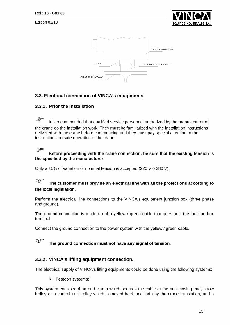
� The personnel who are screwing the legs must be pla ced on auxiliary lifting platforms or scaffolds (depending on the height) bu t NEVER using means that are resting on the same crane or gantry crane that are assembling! Once the crane is lifted and placed, it must be positioned over the crane runaways. This operation is very delicate by the risk that it involves. Check that the crane lenght corresponds to the existing runaways with a maximum difference of ±1 mm. Before resting the equipment over the guides, check that the wheels flange are perfectly placed over the runaways’ solid square rail.
Step 1 Step 2
Step 3 Step 4
Crane 1 Crane 2
Crane 2 Crane 1
RReeff..:: 1188 -- CCrraanneess
EEddiittiioonn 0011//1100
15
3.3. Electrical connection of VINCA’s equipments 3.3.1. Prior the installation
� It is recommended that qualified service personnel authorized by the manufacturer of the crane do the installation work. They must be familiarized with the installation instructions delivered with the crane before commencing and they must pay special attention to the instructions on safe operation of the crane.
� Before proceeding with the crane connection, be sur e that the existing tension is the specified by the manufacturer. Only a ±5% of variation of nominal tension is accepted (220 V ó 380 V).
� The customer must provide an electrical line with a ll the protections according to the local legislation. Perform the electrical line connections to the VINCA’s equipment junction box (three phase and ground). The ground connection is made up of a yellow / green cable that goes until the junction box terminal. Connect the ground connection to the power system with the yellow / green cable.
� The ground connection must not have any signal of t ension. 3.3.2. VINCA’s lifting equipment connection. The electrical supply of VINCA’s lifting equipments could be done using the following systems:
� Festoon systems: This system consists of an end clamp which secures the cable at the non-moving end, a tow trolley or a control unit trolley which is moved back and forth by the crane translation, and a
END CARRIAGE
WHEEL
CRANE RUNWAY
SOLID SQUARE RAIL
RReeff..:: 1188 -- CCrraanneess
EEddiittiioonn 0011//1100
16
series of intermediate trolleys supporting the cable. The trolleys roll smoothly in a specially formed “C” shaped track.
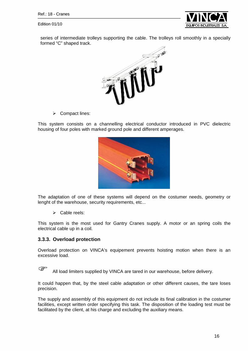
� Compact lines:
This system consists on a channelling electrical conductor introduced in PVC dielectric housing of four poles with marked ground pole and different amperages.
The adaptation of one of these systems will depend on the costumer needs, geometry or lenght of the warehouse, security requirements, etc...
� Cable reels: This system is the most used for Gantry Cranes supply. A motor or an spring coils the electrical cable up in a coil. 3.3.3. Overload protection Overload protection on VINCA’s equipement prevents hoisting motion when there is an excessive load.
� All load limiters supplied by VINCA are tared in our warehouse, before delivery. It could happen that, by the steel cable adaptation or other different causes, the tare loses precision. The supply and assembly of this equipment do not include its final calibration in the costumer facilities, except written order specifying this task. The disposition of the loading test must be facilitated by the client, at his charge and excluding the auxiliary means.
RReeff..:: 1188 -- CCrraanneess
EEddiittiioonn 0011//1100
17
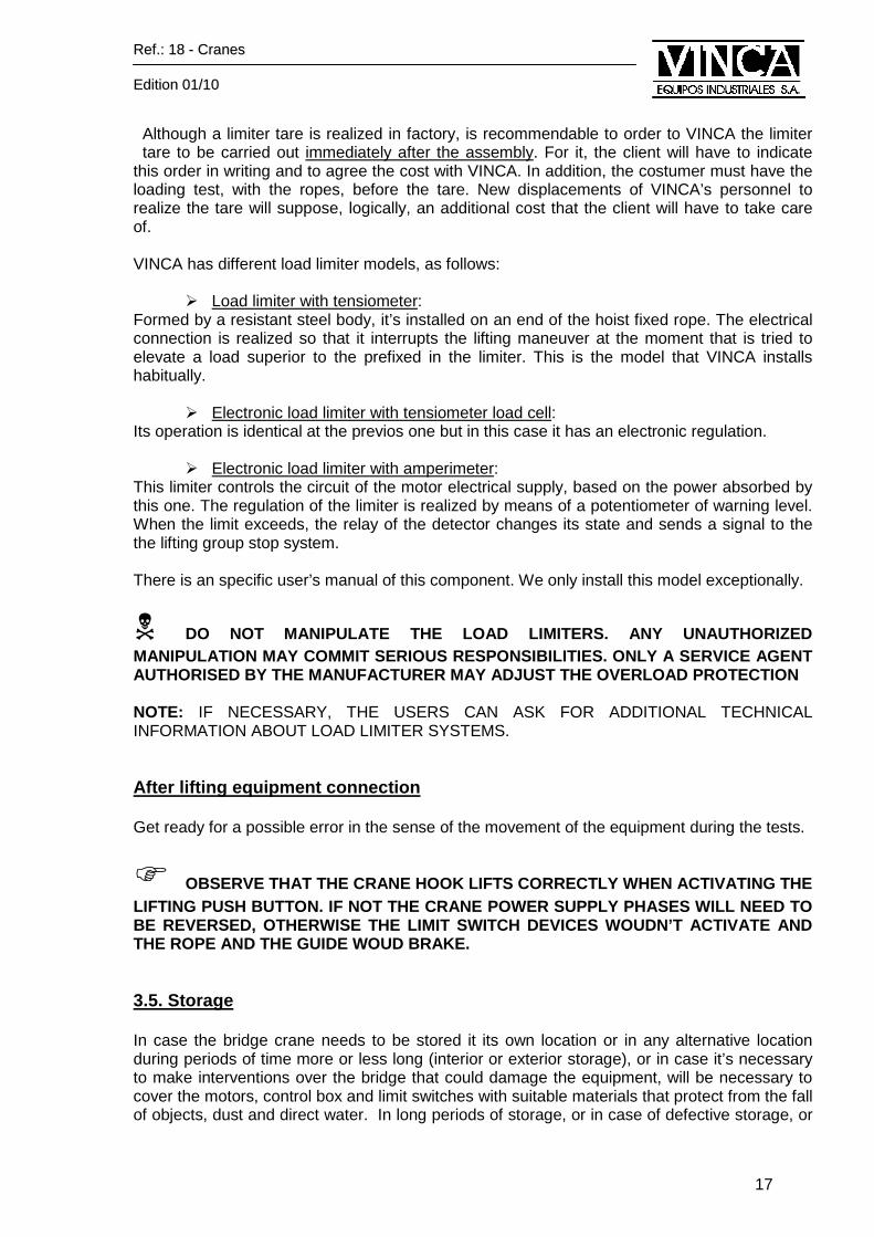
Although a limiter tare is realized in factory, is recommendable to order to VINCA the limiter tare to be carried out immediately after the assembly. For it, the client will have to indicate
this order in writing and to agree the cost with VINCA. In addition, the costumer must have the loading test, with the ropes, before the tare. New displacements of VINCA’s personnel to realize the tare will suppose, logically, an additional cost that the client will have to take care of. VINCA has different load limiter models, as follows:
� Load limiter with tensiometer: Formed by a resistant steel body, it’s installed on an end of the hoist fixed rope. The electrical connection is realized so that it interrupts the lifting maneuver at the moment that is tried to elevate a load superior to the prefixed in the limiter. This is the model that VINCA installs habitually.
� Electronic load limiter with tensiometer load cell: Its operation is identical at the previos one but in this case it has an electronic regulation.
� Electronic load limiter with amperimeter: This limiter controls the circuit of the motor electrical supply, based on the power absorbed by this one. The regulation of the limiter is realized by means of a potentiometer of warning level. When the limit exceeds, the relay of the detector changes its state and sends a signal to the the lifting group stop system. There is an specific user’s manual of this component. We only install this model exceptionally.
� DO NOT MANIPULATE THE LOAD LIMITERS. ANY UNAUTHORI ZED MANIPULATION MAY COMMIT SERIOUS RESPONSIBILITIES. O NLY A SERVICE AGENT AUTHORISED BY THE MANUFACTURER MAY ADJUST THE OVERL OAD PROTECTION NOTE: IF NECESSARY, THE USERS CAN ASK FOR ADDITIONAL TECHNICAL INFORMATION ABOUT LOAD LIMITER SYSTEMS. After lifting equipment connection Get ready for a possible error in the sense of the movement of the equipment during the tests.
� OBSERVE THAT THE CRANE HOOK LIFTS CORRECTLY WHEN AC TIVATING THE LIFTING PUSH BUTTON. IF NOT THE CRANE POWER SUPPLY PHASES WILL NEED TO BE REVERSED, OTHERWISE THE LIMIT SWITCH DEVICES WOUDN’T ACTIVATE AND THE ROPE AND THE GUIDE WOUD BRAKE. 3.5. Storage In case the bridge crane needs to be stored it its own location or in any alternative location during periods of time more or less long (interior or exterior storage), or in case it’s necessary to make interventions over the bridge that could damage the equipment, will be necessary to cover the motors, control box and limit switches with suitable materials that protect from the fall of objects, dust and direct water. In long periods of storage, or in case of defective storage, or
RReeff..:: 1188 -- CCrraanneess
EEddiittiioonn 0011//1100
18
if damages in the equipment are appreciated, it will be necessary to contract a new starting up or a preventive maintenance before his new use.
� Warning The protection is especially necessary in construction sites in which the bridge has mounted previously to works that will be realized in superior levels! The installation of protections is not included in the crane delivery and is responsibility of the client to carry it out. We remember that the guarantee does not cover failures and damages caused by a inadequate maintenance 3.6. Equipment dismantling
� It is recommended that qualified service personnel authorized by the manufacturer of the hoist do the installation work. In order to dismantle the crane, act as follows: 1. Disconnect the crane from the electrical supply. Be sure that the power source has been
locked out before starting with the dismantling. 2. Dismantle and lower the translation trolley at floor level. Use a self-supporting crane or any
other auxiliary system able to develop this work with enough security. 3. Sling properly the crane girders and lower them at floor level. The correct equipment
slinging is explained in section 3.2. 4. Once the crane is on the floor, dismantle the end carriages, loosing the union bolts
between girder crane and end carriage. There is a centering pivot in the union plate to facilitate the assembly – dismantling (explained in section 3.2). Regarding the gantry cranes, follow the procedure explained in section 3.2 but on a reverse order.
3.7. Demolition In the construction phase, VINCA certifies its contribution to the environment with the iron, plastic, paper and oil recycling. For the construction of lifting equipments VINCA has used preferably ferrous materials. There are also aluminum and plastic components. The materials are easily disposable and they don’t represent any environmental pollution risk or against personal security. In the phase of demolition, it’s advisable to separate correctly the different materials in case they will be reused, based on current legislation.
RReeff..:: 1188 -- CCrraanneess
EEddiittiioonn 0011//1100
19
4 OPERATING MODE 4.1. Prior the start up
� Before starting up the Crane, a visual inspection o f all the installation should be done observing that does not exist any defect in th e assembly nor obstacles in the course of equipment.
� Do not activate the equipment without following the safety instructions detailed in this
manual. � Verify that maintenance personnel or unauthorized people isn’t near the equipment location
and that the crane runaway and electrical cables do not present objects that could obstruct them.
� If the equipment has movement locking devices, they must be released before using it. � Before connecting the main supply, be sure that all the controls are in position 0. � Check that all the safety switches are working correctly. � Check that all the brakes are working correctly. � Avoid any manipulation that may put the security at risk. 4.2. Start up and operation
� This manual should be thoroughly read and understoo d before beginning the operation or servicing of this crane. Pay special attention to the instructions on safe operation of the crane. � Activate the main switch. (This switch is placed at the general supply line). � Before carrying out any task of elevation, be sure that the hoist accessories are safely
located in the lifting surface of the hook and that the safety catch of this one is closed. � Before activating the lifting and transport equipment, be sure that you know a safe and
effective route to move the load. � Lift the load enough to avoid collisions with objects during its displacement. However, don’t
lift the load to a height superior to the necessary one in each occasion. Don’t lift the hook until the safety limit superior.
� Start and stop the traveling motion at low speed to prevent the load from swinging excessively. Avoid swinging the hook or load during travel motion.
� Move the load to the desired point. � Lower the load until position it on a safe level of support. � Do not leave a suspended load unattended. � In a potentially dangerous situation, all the hoist movements could be stop pressing the
emergency pushbutton. Don’t use this button if is not necessary. � If some dysfunction in the Crane is detected, stop the work immediately, position the Crane
in safe place and warn immediately to the person or department responsible. � Once the work has finalized, be sure to protect the Crane against any unauthorized use.
Push the button of cancellation of maneuvers, so that a mistaken later pulsation does not generate an erroneous maneuver.

RReeff..:: 1188 -- CCrraanneess
EEddiittiioonn 0011//1100
20
4.3. Using the pushbutton controller.
1. Movement pushbuttons. 2. Hoist selection pushbutton (only if the pushbutton controls several hoists) 3. ON pushbutton and warning signal. 4. Emergency stop pushbutton. 5. Screen.
4.4 Stopping the equipment. � To avoid obstructing the traffic lift enough the empty hook or the loading mechanism. Do
not lift it until the security upper limit. � Place all the controls in situation “0”. � Push the emergency stop pushbutton before opening the main contact. � Disconnect the security switch of main electric current. � Close the mechanical brakes (optional, for ex in case of winds that may move the crane
sliding it on the rails). � Report about any detected fault to the person in charge.

RReeff..:: 1188 -- CCrraanneess
EEddiittiioonn 0011//1100
21
5. MAINTENANCE 5.1. Safety instructions � Execute the habitual tasks of inspection and preventive maintenance according to these
instructions. Maintain a record of the inspection and maintenance tasks. Regular procedures of maintenance and inspection for the safe and effective operation of the equipment are necessary.
� Pay special attention to the brake operation, the limit switches, the hook condition, the cable and the pushbutton controller. It is fundamental that the safety devices (protective devices against overload, limit switches, etc) work correctly and that they are in perfect state of operation, since they protect against any human error.
� The equipment maintenance must be executed only by qualified personnel authorized by the manufacturer of the equipment. The maintenance personnel must be familiarized with the instructions of maintenance and inspection.
� Use only original spare parts approved by the manufacturer of lifting equipment. � Any modification or addition realized in the structure or output values of the equipment
must be dealt first with the manufacturer. � Any task of inspection or repair carried out in the equipment after an overload or collision
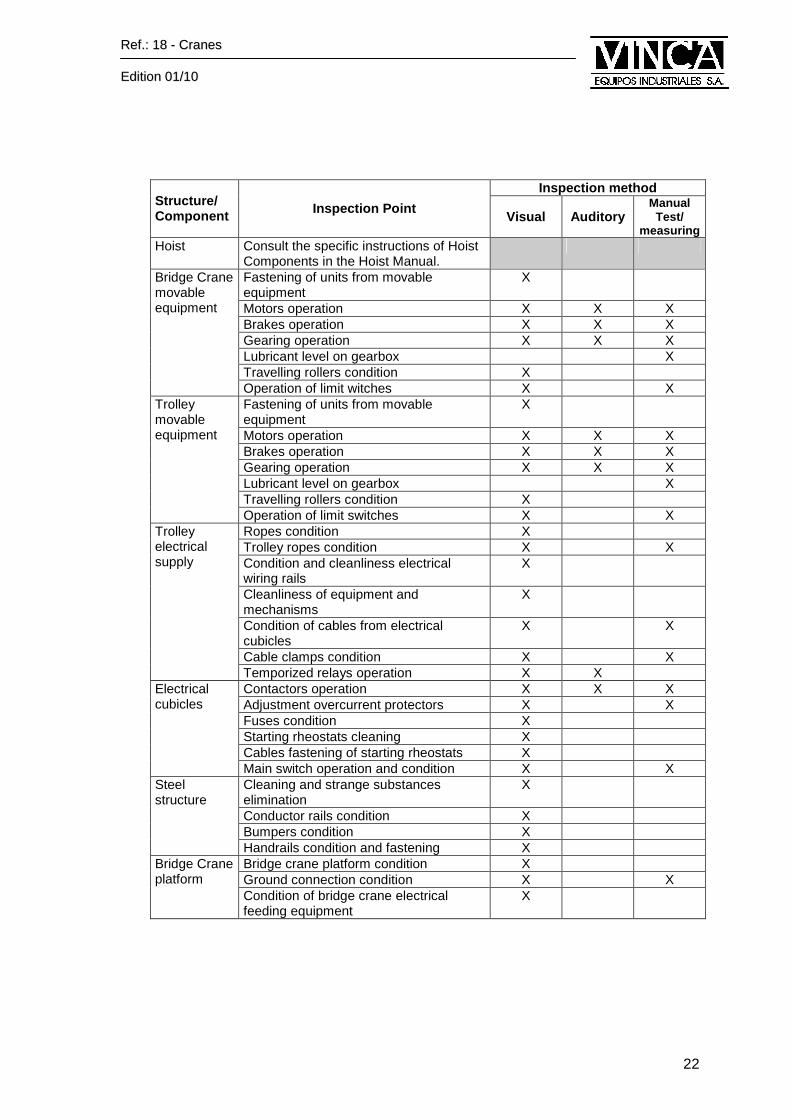
must be dealt with the manufacturer. 5.2. Preventive Maintenance Program 5.2.1. Bridge Crane / Gantry Crane Maintenance The interval of a crane inspection in continuous operation is one week. The cranes that are intermittently used must be inspected before using them. The measures that are executed in the inspection points are necessary if other methods do not produce a suitable result. If some type of defect or anomaly is observed, it must be investigated and execute corrective actions according to the specific instructions for this device.
� If the works of maintenance present some difficulty , contact with VINCA Service Department. The table of the following page enumerates some general points of inspection of the crane as well as the methods to follow.
� Attached is the document “Maintenance Card and Oper ating record of maintenance”, to facilitate the inspection and moni toring workings.
RReeff..:: 1188 -- CCrraanneess
EEddiittiioonn 0011//1100
22
Inspection method Structure/ Component Inspection Point
Visual Auditory Manual
Test/ measuring
Hoist Consult the specific instructions of Hoist Components in the Hoist Manual.
Fastening of units from movable equipment
X
Motors operation X X X Brakes operation X X X Gearing operation X X X Lubricant level on gearbox X Travelling rollers condition X
Bridge Crane movable equipment
Operation of limit witches X X Fastening of units from movable equipment
X
Motors operation X X X Brakes operation X X X Gearing operation X X X Lubricant level on gearbox X Travelling rollers condition X
Trolley movable equipment
Operation of limit switches X X Ropes condition X Trolley ropes condition X X Condition and cleanliness electrical wiring rails
X
Cleanliness of equipment and mechanisms
X
Condition of cables from electrical cubicles
X X
Cable clamps condition X X
Trolley electrical supply
Temporized relays operation X X Contactors operation X X X Adjustment overcurrent protectors X X Fuses condition X Starting rheostats cleaning X Cables fastening of starting rheostats X
Electrical cubicles
Main switch operation and condition X X Cleaning and strange substances elimination
X
Conductor rails condition X Bumpers condition X
Steel structure
Handrails condition and fastening X Bridge crane platform condition X Ground connection condition X X
Bridge Crane platform
Condition of bridge crane electrical feeding equipment
X
RReeff..:: 1188 -- CCrraanneess
EEddiittiioonn 0011//1100
23
5.2.2. Hoist Maintenance
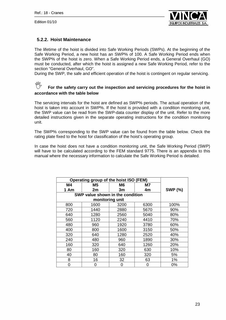
The lifetime of the hoist is divided into Safe Working Periods (SWPs). At the beginning of the Safe Working Period, a new hoist has an SWP% of 100. A Safe Working Period ends when the SWP% of the hoist is zero. When a Safe Working Period ends, a General Overhaul (GO) must be conducted, after which the hoist is assigned a new Safe Working Period, refer to the section “General Overhaul, GO”. During the SWP, the safe and efficient operation of the hoist is contingent on regular servicing.
� For the safety carry out the inspection and servici ng procedures for the hoist in accordance with the table below The servicing intervals for the hoist are defined as SWP% periods. The actual operation of the hoist is taken into account in SWP%. If the hoist is provided with a condition monitoring unit, the SWP value can be read from the SWP-data counter display of the unit. Refer to the more detailed instructions given in the separate operating instructions for the condition monitoring unit. The SWP% corresponding to the SWP value can be found from the table below. Check the rating plate fixed to the hoist for classification of the hoist’s operating group. In case the hoist does not have a condition monitoring unit, the Safe Working Period (SWP) will have to be calculated according to the FEM standard 9775. There is an appendix to this manual where the necessary information to calculate the Safe Working Period is detailed.
Operating group of the hoist ISO (FEM) M4
1 Am M5 2m
M6 3m
M7 4m
SWP value shown in the condition monitoring unit
SWP (%)
800 1600 3200 6300 100% 720 1440 2880 5670 90% 640 1280 2560 5040 80% 560 1120 2240 4410 70% 480 960 1920 3780 60% 400 800 1600 3150 50% 320 640 1280 2520 40% 240 480 960 1890 30% 160 320 640 1260 20% 80 160 320 630 10% 40 80 160 320 5% 8 16 32 63 1% 0 0 0 0 0%

RReeff..:: 1188 -- CCrraanneess
EEddiittiioonn 0011//1100
24
The table below shows the service intervals for the hoist in SWP% periods and in calendar
months. Items for inspection and servicing refer to the servicing procedures described earlier in these operating instructions. The servicing procedure must be carried out latest at the end of a SWP% period, or by the end of the stated number of calendar months. Hoists without a condition-monitoring device must follow a servicing procedure guide by calendar months. For ensuring the usability of the hoist the servicing intervals can be shortened.
� In order to guarantee the hoist availability, reduc e the maintenance intervals.
A. Maintenance tasks must be only carried out by maintenance personnel authorized by the hoist manufacturer.
B. Periodical inspecting and servicing procedure may only be carried out by a
serviceman authorized by the hoist manufacturer or service personnel adequately trained by the hoist manufacturer
C. Daily inspection tasks that must be carried out by the user.
SWP Period(%) Mes Items for inspection and servicing Daily
inspection 1% 1
5% 6
10% 12
Inspection of hoisting gear B A Inspection of hoisting motor and brake A Inspection of rope drum B A Inspection of rope guide B A Inspection of rope clamps B A Inspection of wedge frame B A Inspection of wire rope C B A Inspection of hook block C B A Inspection of rope sheave beam1) B A Inspection of hoisting limit switch C A Inspection of overload protector B A Inspection of travelling machinery1) A Inspection of frequency controller1) B A Inspection of trolley wheels1) B A Inspection of buffers1) B A Inspection of pushbutton controller C B A Inspection of condition monitoring unit1) B A Annual inspection according to local requirements2) A
1) Not all hoist types include this equipment. 2) Germany: Inspection according to VBG 8,9 (VBG, Vorschrift der Berufsgenossenschaft)
RReeff..:: 1188 -- CCrraanneess
EEddiittiioonn 0011//1100
25
5.2.3 General Overhaul (GO) Once the SWP% of the hoist reaches zero, the hoist has exhausted its theoretical lifetime. The probability of a defect in the hoist is therefore higher and operating safety is jeopardized. When the theoretical lifetime is exhausted, a General Overhaul (GO) of the hoist must be conducted. Only the hoist manufacturer or a service organizati on authorized by the hoist manufacturer may conduct a GO . The components in the hoist that have an impact on hoist lifetime are inspected in a GO and critical components are replaced. A new theoretical SWP is given to the hoist after completion of a GO.
� When the Safe Working Period (SWP) of the hoist is exhausted, the hoist may only be used after a GO has been conducted.
5.3. Travelling reducers Replacement or dismantling instructions: First loosen the fixing bolts and remove the reducer. Before the assembly, is important to check the following points: � The base of support and fixation of the reducer must be rigid, flat and to be mechanized, in
order to secure a good support and to avoid vibrations. � Carefully align the motor and machine axes with the reducer ones, avoiding any angular or
radial displacement between them. � The transmission parts such as connections, pinions, motors, etc, will be correctly
assembled, using the threaded holes placed in the reducer axes, avoiding any blow or leverage on them.
5.4. Travelling brakes regulation
� Due to the existence of different types of motors and to the difficulty that the correct accomplishment of this task presents, it is advised that only specialized technical personnel should carry it out. Attached to this manual, some technical information referring to the motors installed in the lifting and traveling equipment is provided. 5.5. Criteria about wire rope examination and repl acement
� In order to ensure safe and efficient operation of the hoist, it is essential to monitor the ropes and, if necessary, remove and rep lace them at the adequated moment. Regular inspection of the rope is a vital s afety procedure requirement.
�The rope shall be changed before the limits have be en reached. Change the rope if
there is a risk that limits are reached before the next examination .
RReeff..:: 1188 -- CCrraanneess
EEddiittiioonn 0011//1100
26
5.5.1 Servicing frequency
� Daily examinations: Visual deformations and damages in the rope shall be inspected daily by the user. Pay special attention to the anchorage points to the machine.
� Periodical examinations: The periodical examinations should be determined based on the following :
� The prescribed exigencies that are applied to equipment in which the cable is used. � The type of material and the rope working conditions. � The equipment duty class group. � Previous examinations results.
In any case, an inspection must be always realized after an incident, an startup and any disassembly followed by a new assembly. 5.5.2 Points to be checked during examinations Although the ropes must be examined in all their length, is necessary to watch particularly:
� The fixing points at the rope ends both the active and the inactive ropes (A description of the areas to be inspected exists, for each fixation type, with its corresponding regulation).
� The rope parts that pass through the blocks and pulleys and for equipment that carry out a repeated work.
� The rope parts that pass through compensating pulleys. � The rope parts that may be usually worn by external causes.
The examination results must be raccorded in doc. annexed “Equipment verification registry”. 5.5.3 Replacement criteria These replacement criteria are very well detailed at UNE 58-111: 1881 (ISO/DIS 4309) regulation. In order to increase information about replacement criteria contact with VINCA Equipos Industriales.
� An appendix regarding the criteria of rope replacem ent exists at disposal of our clients. 5.6. Inspection calendar The inspection calendar intends to maintain at sight the dates of the next inspection to carry out in the crane. This calendar is constituted by a disk where the month and year of the following inspection is marked using red stickers. In section 2.4 there is an image of this calendar.
RReeff..:: 1188 -- CCrraanneess
EEddiittiioonn 0011//1100
27
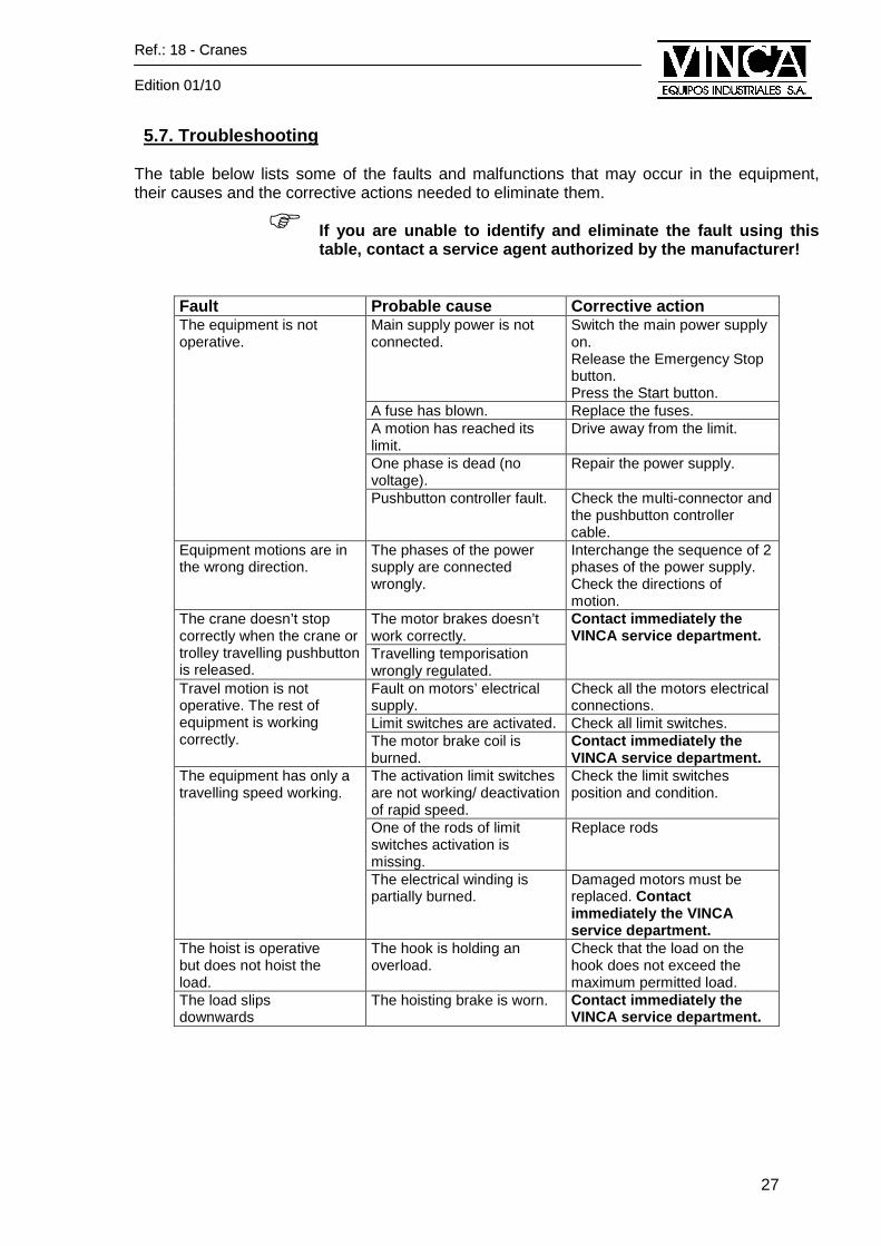
5.7. Troubleshooting The table below lists some of the faults and malfunctions that may occur in the equipment, their causes and the corrective actions needed to eliminate them.
� If you are unable to identify and eliminate the fau lt using this table, contact a service agent authorized by the ma nufacturer!
Fault Probable cause Corrective action Main supply power is not connected.
Switch the main power supply on. Release the Emergency Stop button. Press the Start button.
A fuse has blown. Replace the fuses. A motion has reached its limit.
Drive away from the limit.
One phase is dead (no voltage).
Repair the power supply.
The equipment is not operative.
Pushbutton controller fault. Check the multi-connector and the pushbutton controller cable.
Equipment motions are in the wrong direction.
The phases of the power supply are connected wrongly.
Interchange the sequence of 2 phases of the power supply. Check the directions of motion.
The motor brakes doesn’t work correctly.
The crane doesn’t stop correctly when the crane or trolley travelling pushbutton is released.
Travelling temporisation wrongly regulated.
Contact immediately the VINCA service department.
Fault on motors’ electrical supply.
Check all the motors electrical connections.
Limit switches are activated. Check all limit switches.
Travel motion is not operative. The rest of equipment is working correctly. The motor brake coil is
burned. Contact immediately the VINCA service department.
The activation limit switches are not working/ deactivation of rapid speed.
Check the limit switches position and condition.
One of the rods of limit switches activation is missing.
Replace rods
The equipment has only a travelling speed working.
The electrical winding is partially burned.
Damaged motors must be replaced. Contact immediately the VINCA service department.
The hoist is operative but does not hoist the load.
The hook is holding an overload.
Check that the load on the hook does not exceed the maximum permitted load.
The load slips downwards
The hoisting brake is worn. Contact immediately the VINCA service department.

VINCA EQUIPOS INDUSTRIALES, S.A.
Pol. Ind. Torre Bovera – C/. Técnica 39 08740 ST. ANDREU DE LA BARCA (Barcelona)
Teléfono: (93) 635 61 20 – Fax: (93) 635 61 30 www.vinca.net
6. APPENDIX
The following Appendix are at disposal of VINCA lif ting and travelling equipment users:
� Hoist manual.
� Motors technical information.
� Instructions how to calculate Safe Working Periods (SWP).
� Criteria about wire rope examination and replacement.
� Spare parts list.
� Inspection points and maintenance records.
� Certificates (CE, rope or chain, hook and loading factory tests).
VINCA EQUIPOS INDUSTRIALES, S.A.
Pol. Ind. Torre Bovera – C/. Técnica 39 08740 ST. ANDREU DE LA BARCA (Barcelona)
Teléfono: (93) 635 61 20 – Fax: (93) 635 61 30 www.vinca.net
APPENDIX
MAINTENANCE AND BREAKDOWNS HISTORICAL RECORD
Doc.: Cranes Manual VINCA
Ver 01-10 EN.DOC
Ed.: 08/09 Rev.: 0 Autor: SM 30 de
32
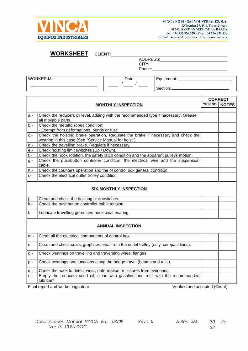
WORKSHEET CLIENT: ADDRESS: CITY: Phone:
WORKER Mr.:
Date / /
Equipment: _______________________ Section:
CORRECT MONTHLY INSPECTION YES/ NO NOTES a.- Check the reducers oil level, adding with the recommended type if necessary. Grease
all movable parts.
b.- Check the metallic ropes condition: - Exempt from deformations, bends or rust
c.- Check the hoisting brake operation. Regulate the brake if necessary and check the wearing in this case.(See "Service Manual for hoist")
d.- Check the travelling brake. Regulate if necessary. e.- Check hoisting limit switches (Up / Down). f.- Check the hook rotation, the safety latch condition and the apparent pulleys motion. g.- Check the pushbutton controller condition, the electrical wire and the suspension
cable.
h.- Check the counters operation and the of control box general condition. i.- Check the electrical outlet trolley condition.
SIX-MONTHLY INSPECTION
j.- Clean and check the hoisting limit switches. k.- Check the pushbutton controller cable tension.
l.- Lubricate travelling gears and hook axial bearing.
ANNUAL INSPECTION
m.- Clean all the electrical components of control box.
n.- Clean and check coals, graphites, etc.. from the outlet trolley (only compact lines).
o.- Check wearings on travelling and traversing wheel flanges.
p.- Check wearings and junctions along the bridge travel (beams and rails).
q.- Check the hook to detect wear, deformation or fissures from overloads. r.- Empty the reducers used oil, clean with gasoline and refill with the recommended
lubricant.
Final report and worker signature Verified and accepted (Client)

Doc.: Cranes Manual VINCA
Ver 01-10 EN.DOC
Ed.: 08/09 Rev.: 0 Autor: SM 31 de
32
MAINTENANCE AND BREAKDOWNS HISTORICAL RECORD
Maintenance register sheet
Preventive and extraordinary Maintenance operations register
Date Kind of operation Remarks and signature