cranfleld - defense technical information · pdf filecranfleld defence college of management...
TRANSCRIPT

CranfleldDefence College of Management NWERSITY
and Technology
Department of
Aerospace,
Power &
Sensors
TECHNICAL REPORT DAPSALM/1 15/2005
Ivor L. Morrow
September, 2005
Grant-04-3005 20060414061DTIC Copy
Distribution A:Approved for public release;
distribution is unlimited.
Final Progress Report: Launching of EM
Surface Waves On Axial Cylindrical
Reactive Surface with Negative Permittivity
REPORT DOCUMENTATION PAGE Form Approved OMB No. 0704-0188
Public reporting burden for this collection of information is estimated to average 1 hour per response, including the time for reviewing instructions, searching existing data sources, gathering andmaintaining the data needed, and completing and reviewing the collection of information. Send comments regarding this burden estimate or any other aspect of this collection of information,including suggestions for reducing the burden, to Department of Defense, Washington Headquarters Services, Directorate for Information Operations and Reports (0704-0188), 1215 JeffersonDavis Highway, Suite 1204, Arlington, VA 22202-4302. Respondents should be aware that notwithstanding any other provision of law, no person shall be subject to any penalty for failing to complywith a collection of information if it does not display a currently valid OMB control number.PLEASE DO NOT RETURN YOUR FORM TO THE ABOVE ADDRESS.
1. REPORT DATE (DD-MM-YYYY) 2. REPORT TYPE 3. DATES COVERED (From - To)09-11-2005 Final Report 23 March 2004 - 23-Mar-05
4. TITLE AND SUBTITLE 5a. CONTRACT NUMBERFA8655-04-1-3005
Launching of Electromagnetic Surface Waves on Axial Cylindrical Reactive
Surface with Negative Permittivity 5b. GRANT NUMBER
5c. PROGRAM ELEMENT NUMBER
6. AUTHOR(S) 5d. PROJECT NUMBER
Dr. Ivor L Morrow
5d. TASK NUMBER
5e. WORK UNIT NUMBER
7. PERFORMING ORGANIZATION NAME(S) AND ADDRESS(ES) 8. PERFORMING ORGANIZATIONRoyal Military College of Science (RMCS), Cranfield University REPORT NUMBERDept. of Aerospace, Power and SensorsSwindon SN6 8LA N/AUnited Kingdom
9. SPONSORING/MONITORING AGENCY NAME(S) AND ADDRESS(ES) 10. SPONSOR/MONITOR'S ACRONYM(S)
EOARDPSC 802 BOX 14FPO 09499-0014 11. SPONSOR/MONITOR'S REPORT NUMBER(S)
SPC 04-3005
12. DISTRIBUTION/AVAILABILITY STATEMENT
Approved for public release; distribution is unlimited.
13. SUPPLEMENTARY NOTES
14. ABSTRACT
This report results from a contract tasking Royal Military College of Science (RMCS), Cranfield University as follows: The Grantee willinvestigate methods for reducing radar cross section of antennas. Specifically: 1.) Formulation of the antenna and waveguide launcherproblem: (i) Define intra- and exterior-field forms on the antenna, (ii) define negative permittivity expressions appropriate to the mediumcomposing the cylindrical radiator, for e.g., plasma or other electronic resonant media (meta-materials), (iii) formulate eigenfunctionencompassing antenna and waveguide structure, and then determine (iv) the eigenvalues of the principal supported modes. 2.) Formulatesolutions for the scattered fields by; (i) applying boundary conditions and (ii) decomposing the total field into its incident and scattered fieldcomponent. 3) Derive functional theoretic transforms for the scattered fields. The likely mathematical steps will include (i) splitting thescattered field expressions into its bi-laterial Laplace equivalence and then (ii) Fourier transform expressions to z and/or w planes. 4.)Evaluate scattered field solutions via Wiener-Hopf integrals to determine (i) total average power transmitted to the surface, (ii) total averagereflected and (iii) total power radiated, per unit incident power.
15. SUBJECT TERMSEOARD, Physics, Antennas
16. SECURITY CLASSIFICATION OF: 17. LIMITATION OF 18, NUMBER 19a. NAME OF RESPONSIBLE PERSONa.REOR b ASRAT . HIPAE ABSTRACT OF PAGES MICHAEL KJ MILLIGAN, Lt Col, USAF
UNCLAS UNCLAS UNCLAS UL24 19b. TELEPHONE NUMBER (Include area code)
+44 (0)20 7514 4955
Standard Form 298 (Rev. 8/98)Prescribed by ANSI Std. Z39-18

ALL RECIPIENTS OF THIS REPORT ARE ADVISED THAT IT MUST NOT
BE COPIED IN WHOLE OR IN PART OR BE GIVEN FURTHER DISTRI-
BUTION OUTSIDE THE AUTHORITY WITHOUT THE WRITTEN AP-
PROVAL OF THE DIRECTOR OF THE AIR FORCE OFFICE OF SCIEN-
TIFIC RESEARCH, AIR FORCE MATERIAL COMMAND, USAF.
The investigation which is the subject of this Report was initiated by the Director
of the Air Force Office of Scientific Research, Air Force Material Command,
USAF and was carried out under the terms of grant/cooperative award number
FA8655-04-1-3005.
Executive summary
This document is a deliverable for the study Launching of Electromagnetic Sur-
face Waves on Axial Cylindrical Reactive Surfaces with Negative Permittivity under the
grant/cooperative award no. FA8655-04-1-3005 and was issued by the EOARD.
In this, the final report, the excitation of the dominant TM surface wave on an axial
reactive surface composed of a material of negative permittivity is again discussed using
a different and more accurate analyses. Here we tackle the problem using a Wiener-
Hopf treatment. The geometry is slightly modified from that described in the interim
report to allow variation in some of the launcher parameters. The surface wave launcher
now consists of a metallic cylindrical surface of radius b coaxial with a cylindrical rod of
negative permittivity material of radius a, where b > a. The reactive surface extends from
I = -oo < z < 1, and the conducting surface extends from -cc < z < 0. The incident
field is the dominant TM mode excited in the coaxial structure and propagating in the
positive z-direction.
Numerical results are presented for the coupling of power to the surface wave, the
reflected wave and the radiated field on the plasma rod. The calculations were performed
over a wide range of w,/w values. The case of waveguide excitation, i.e b = a, was
compared were applicable with the results obtained using the two approximate aperture
distributions. The case of coaxial excitation, i.e. b > a, was also briefly considered using
the Wiener-Hopf analyses. The calculated launcher efficiency was shown to increase as
the b/a ratio increased.

Contents
1 Introduction 1
1.1 Background ......... ..................................... 1
1.2 Scope ............ ........................................ 2
2 Modal Fields and Eigenfunctions 3
2.1 Coaxial Launcher for Axial Cylindrical Antenna ...................... 3
2.2 Axial Cylindrical Antenna .................................... 4
2.3 Laplace Transformation of Scattered Field ......................... 6
2.4 Solution of Transformed Scattered Field ........................... 7
2.4.1 Wiener-Hopf Factorisation ................................ 8
2.4.2 Scattered Field Inversion Integral ........................... 10
3 Power Flow and Antenna Efficiency 12
4 Computed Results 14
4.1 Radiated Fields ......... ................................... 14
4.2 Power Propagated and Radiated ........ ......................... 15
4.3 Waveguide Launcher Efficiency ........ .......................... 15
4.4 Coaxial Launcher Efficiency ........ ............................ 18
5 Conclusions 19
6 Recommendations for Future Work 21
7 Acknowledgements 22
8 References 23
ii

List of Figures
1 Surface Wave Structure ...................................... 2
2 Complex Plane Diagram ......... .............................. 9
3 The Inversion Contour in the Complex 03 Plane ....................... 11
4 Radiation pattern due to fields on the radial surface of the cylindrical plasma
supporting the TM01 mode for various wp/w ratios .................... 16
5 (Contn). Radiation pattern due to fields on the radial surface of the cylindrical
plasma supporting the TM0 1 mode for various wp/w ratios ............... 17
6 Ratio of Powers Coupled from the Incident Wave to the Surface Wave, Re-
flected Surface Wave and Radiated Field for the TM01 mode ............. 18
7 Computed Launcher Efficiency for Cylindrical Waveguide Excitation ...... .19
8 Computed Launcher Efficiency for Cylindrical Waveguide and Coaxial Exci-
tation .......... ......................................... 20
iii

List of Tables
1 Table of Surface Impedance versus Plasma frequency ratios at r = a ...... . 14
iv
Morrow 1 Introduction
1 Introduction
1.1 Background
The problem of exciting surface waves on conventional dielectric rod antennas was widely
treated in the 1960 and 70's literature. This extensive treatment was motivated largely by the
inherently low attenuation and large bandwidth available in some surface wave launchers. An
excellent survey on the types of surface waves and surface wave radiation useful in dielectric
rod communication antennas has been collated by Chatterjee in [1, 2] and electrically small
dielectric antenna by Luk [3]. Recently, researchers have returned to the subject with a
view to constructing these antenna from novel dielectric and permeability materials that
can support surface waves. These materials should be lightweight and robust and behave as
anisotropic ferrite and/or plasma analogues. A knowledge of the properties of the surface
wave and plasma material properties [4] associated with these structures can provide useful
insight into their radiation mechanism and characteristics.
A common problem, whether using a conventional dielectric or otherwise, to host the
surface and interior fields, is the efficient excitation or launching of the guided electromagnetic
surface wave. A general requirement for a good surface wave launcher is a high launcher
efficiency over a large bandwidth. As was pointed out in the interim report, when the
surface wave fields are of infinite extent, the launcher in theory should also be of infinite
extent to achieve a 100% launcher efficiency. Brown demonstrated theoretically [5] that the
launching efficiency of a finite-sized launcher could approach 100%; but this large efficiency
was realised only at the expense of frequency bandwidth.
The majority of reported numerical techniques consider the excitation source to be either
infinitesimally short electric and/or magnetic dipole current sources. A finite-sized aperture
could be handled, at least in theory, by a superposition of infinitesimal sources. In practice,
the outcome has an unknown accuracy since the formulation fails to take account of the
losses in the reflected field at the launcher. Secondly, because the aperture distribution may
be unknown. In the interim report [6], the aperture distribution was approximated by a
"chopped" surface wave distribution; that is, the fields in the aperture plane are assumed to
have the same form as the surface wave fields within the aperture and are assumed to vanish
everywhere outside of the aperture. Another often used approximation method is Kirchhoff's
Page 1 of 24

Morrow 1.2 Scope
approximation. In this method the aperture field is assumed to be of the same form as the
unperturbed incident field. This distribution was also computed in the interim report [6]
and the launcher efficiency results were found to be poorer than those obtained using the
equivalent aperture technique. The principal reason for the discrepancy was attributed to
the differing radiation patterns obtained as the ratio wp/w was increased. The radiated
fields were computed by both methods by an integration over the aperture plane (the surface
wave modes and the radiation field are orthogonal [7]). The accuracy of the results obtained
using these approximation techniques is usually unknown since no criterion exists which can
determine the extent of the approximation.
1.2 Scope
The purpose of this report is to (i) present an exact analysis, using Laplace transform and
Weiner-Hopf factorisation techniques (ii) and numerical results for the radiation pattern,
bandwidth and launching characteristics for a finite-sized launcher. These results will then
be compared with (iii) the results obtained in the interim report [6] for the "equivalent
end-aperture" and Kirchhoff's approximations to determine under what conditions the ap-
proximate techniques are valid.
r
a b
Figure 1: Surface Wave Structure.
A good deal of the ground work identifying the plasma cylinder dimensions, useful ma-
terial properties and resonant eigenmodes was performed in [6]. The analysis considers the
geometry shown in Fig. 1. The waveguide launching section has been modified from that
in the interim report to allow for the possibility that b > a i.e. coaxial excitation and when
b = a, a cylindrical waveguide excitation as in the interim report. This modification has the
Page 2 of 24

Morrow 2 Modal Fields and Eigenfunctions
merit of generalising the analysis and design parameters but comes with an increased cost
in analytic complexity. The surface wave field here is now taken account of by specifying
a surface impedance. The surface impedance is the ratio of tangential electric to magnetic
field on the surface of the wave guiding structure. This numerical value will depend on the
composition of the structure and the polarisation of the propagating field.
The structure consists of a reactive negative permittivity cylindrical surface of radius
a and of infinite extent in the z-direction. Coaxial with this cylinder is a thin, perfectly
conducting surface of radius b for z < 0. The surface wave field, radiation field, and the
reflected field will be computed when the incident field is the dominant TMoo mode in the
region a < r < b, z < 0 propagating to the right. In this analysis the fields in the region
r < a are not needed and if they exist will not be considered in the calculations of power.
2 Modal Fields and Eigenfunctions
2.1 Coaxial Launcher for Axial Cylindrical Antenna
This problem can be handled with the Wiener-Hopf technique. The procedure to be followed
is similar to that used by [8, 7]. The analysis will be carried out for a range in the parameters
of the structure where only the dominant TMoo mode propagates in the region a < r < b, z <
0. The total field in this case can be derived from a scalar function 0(r, z) because of the
circular symmetry of the structure. The function O(r, z) is the 0 component of the magnetic
field. In the region a < r < b and z < 0, O(r, z) can be expanded in a series of eigenfunctions
[9, 10],
0(r,z) = Ao[J 1(-jpor)HO2 (-jpob)
-Jo(-jpob)Ji (-jpor)H(2) (-jpor)]exp(--oz)
+ =1 jA[Ji(pnr)H2 (pnb)
- Jo(pnb)gH(2) (pnr)]exp(-YnZ)()
where the An are the propagation constants'. The Jo, Ji represent Bessel functions of
the first and second kind of zero and first order, and () H, 2 are Hankel functions of first0 , 0
'A time dependence of exp(jwt) is assumed.
Page 3 of 24

Morrow 2.2 Axial Cylindrical Antenna
and second kind or order zero. The presence of a complex argument indicates the wave is
attenuated, or augmented, in the outward traveling direction. The eigenvalues p" and the
propagation constant -y, satisfy the equations
-yd - PO + ko (2)
2 = p2 - k, for n > 0 (3)
Joa(-jpb) H(2) (-jp~a) - Jo(jp~a)H(2) (-jp,,b)apoa--=- -0 1aa4
J1 (-jpoa)HO2 ) (jpob) - Jo (jpob)gH2) (jpoa)Yo(pnb)Yo(pna) - Jo(pnb)Yo(pna) = a, for n > 0 (5)
poaJO(pnb)Yl(poa) - Ji(pna)Yo(pna) =
ai = kX 8 /Zo (6)
where k 0 is the free-space wave number and Z0 the characteristic impedance of free-space
and Y0 , Y 1 are Bessel functions of the second kind or order zero and one. The eigenvalues p"
are determined by the boundary conditions. The ratio of the axial component of the electric
field to the azimuth component of the magnetic field [11] must equal the surface reactance
jX 8 along the reactive surface at r = a. Along the surface of the perfect conductor r = b the
axial component of electric field must vanish. These conditions have been built into Eqn.
1. If surface reactance tends to zero, then the first term in Eqn 1 will reduce to the TMoo
TEM like wave associated with a coaxial line and the remaining terms will reduce to the
TMon modes for a coaxial line. Alternatively, if b = a, i.e. cylindrical waveguide excitation
then the first term in Eqn. 1 reduces to zero and we are left with only the second term
again permitting only the TMon modes, of which only the dominant TMo1 is considered. It
should be recalled that the total field consists entirely of TMon therefore it is only necessary
to specify the surface reactance for one polarisation of the electric field.
2.2 Axial Cylindrical Antenna
The total field in the open antenna section consists of discrete modes guided by the reactive
structure plus the radiated field. Since the field in the coaxial portion of the structure is
made up entirely from circularly symmetric TM modes, then the field excited in the open
structure must also be circularly symmetric, the only mode that possess circular symmetry
is the TMo1 mode.
Page 4 of 24
Morrow 2.2 Axial Cylindrical Antenna
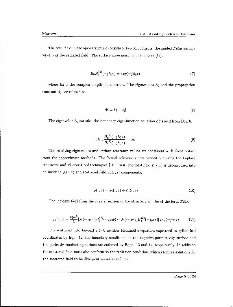
The total field in the open structure consists of two components; the guided TMO, surface
wave plus the radiated field. The surface wave must be of the form [12],
BoH(2)(-jhor) = exp(-j/oz) (7)
where B 0 is the complex amplitude constant. The eigenvalues h0 and the propagation
constant 1o are related as,
0= ho + k0 (8)
The eigenvalue h0 satisfies the boundary eigenfunction equation obtained from Eqn 6.
""Hg22)(-jhoa-------) -_a
jhoa (2) -( a a (9)1 (-jhoa)
The resulting eigenvalues and surface reactance values are consistent with those obtain
from the approximate methods. The formal solution is now carried out using the Laplace
transform and Wiener-Hopf techniques [11]. First, the total field 0(r, z) is decomposed into
an incident Oi (r, z) and scattered field 0, (r, z) components,
0(r, z) = Vi(r, z) + V),(r, z) (10)
The incident field from the coaxial section of the structure will be of the form TMo,
Oi(r, z) = --P-b [Jl(-jpor)H(2)(-jpob) - Jo(-jpob)H(2) (-jpor)] exp(-jyoz) (11)
The scattered field beyond z > 0 satisfies Helmholt's equation expressed in cylindrical
coordinates by Eqn. 12, the boundary conditions on the negative permittivity surface and
the perfectly conducting surface are enforced by Eqns. 13 and 14, respectively. In addition
the scattered field must also conform to the radiation condition, which requires solutions for
the scattered field to be divergent waves at infinity.
Page 5 of 24
Morrow 2.3 Laplace Transformation of Scattered Field
52o9 1 60 2¢ 2)0 =sr-2- + -- + 2 s + (k2 - 1/r2)¢= (12)
3 r 6 6r2
1 (ro,) + ao.s Ir=a= 0 (13)r
111 1 (r¢s) Ir=b,z<0= 0 (14)r 6
2.3 Laplace Transformation of Scattered Field
The scattered field can be expressed as a bi-lateral Laplace transform along with the associ-
ated boundary conditions,
Sr+) = ¢+(r,/3) +&¢(r,/) (15)
where,
= j (r,z) exp(-, z)dz (16)
0-(r,/3) = J O(r, z) exp(-O, z)dz (17)
The scattered field can then be recovered by the inversion integral,
O(r, z) = 1 ¢(r,O) exp(8,3z)d8 (18)27rjJ
To make 0+ (r, 0) and 0- (r, 0) analytic functions of /3 in the complex / region, the free
space wave number k 0 will be made complex. This is equivalent to introducing losses into
the medium surrounding the structure. Let jko = jko + k", where k' and k 0 are real. In the
final solution k" can be made equal to zero to recover the results for the lossless case. Since
k 0 is complex, the propagation constant -yo and 00 will be complex. Therefore, in general
Jho = Jfr' + j-yo' and j8o = j03! + /30. It should be remembered that 0", -Y', %' and -YO" are all
real.
Taking the Laplace transform of Eqns. 12, 13 and 14 yields,
Page 6 of 24

Morrow 2.4 Solution of Transformed Scattered Field
r+ k _ 1/r2)0 = 0 (19)
11- 1 (re) + c¢ Ir=a= 0 (20)
r 6r11r-r(rO-) + 0 1r=b= 0 (21)r 6r
where /3 is restricted to the range -'yg < Re(/3) < -yg.
2.4 Solution of Transformed Scattered Field
In the region a < r < b the proper solution of Eqn. 19 is of the form,
(b [AH 2 (Aa + aHi2 )(Aa)]J 1 (Ar) - [AJo(Aa) + aJl(Aa)]gH2 )(Ar) (22)
(, b(b ,/3) 2)- + aHo2 )(Aa)]Jx(Ab) -[AJo(Aa) + aJi(Aa)]Hi2 )(Ab)
The solution is an even function of A consequently either branch of A can be selected. In
the region r > b the proper solution of Eqn. 19 is,
i~(r, V) '~(b+, 3 ) Hi2(A' r) (23)H2 (A, b)
where A =(k• +/32)1/2. We will now determine expressions for the unknown coefficients
O(b-, /3) and 0(b+, /3) in Eqns. 22 and 23 by using the discontinuity condition on the scattered
field at r = b. This is achieved using some auxiliary functions J+ (b, /3), J- (b, /3) and E+ (b, /3),
where
J+(b, /3) =j [,O8(b+, z) - O(b-, z)] exp(-/3z)dz (24)
J- (b,/3 ¢ (b+, z) - O(b-, z)] exp(-!3z)dz (25)
13E+(b,!3) = rr(ro) I1=b (26)
Is should be mentioned that J-(b,/3) is the Laplace transform of the electric current on
the outer conductor of the coaxial guide at r = b associated with the scattered field. The
function E+ (b, /3) is the transform of the axial component of the total electric field evaluated
Page 7 of 24

Morrow 2.4 Solution of Transformed Scattered Field
at r = b. The function J+(b, 13) can be deduced for the region Re(O) > -yg0 by consideration
of the boundary conditions.
J+(b,/) - (27)
From the definitions of J+ (b,Z3) and J- (b, 1) it is apparent that
0(b+, Z) - ¢(b-, 1) = J+ (b, 0) - J- (b, Z) (28)
The left side of Eqn. 29 may be reduced to,
0(b+, Z) - O(b-, 3) = F(O)E+(b, 13) (29)
where F(O) after analytic manipulation is explicitly written out to give,
F(0) -- 2j H 2 )(Aa) [A& H (Aa) (30)7ibA\2 11(2) +b H 2~A
0 (Ab H)L)(1
0[H•2 ) (A\a)Jo(Ab) - H- 2) (Ab)Jo(Aa)] + o [HO2 ) (Aa)Jo(Ab) - HO2 ) (Ab)J 1 (Aa)]
The function F(O) can be shown to be analytic in the strip -- yg < Re(3) < --yo".
Substituting Eqn. 29 into Eqn. 31 and using the result for J+(b, 1) from Eqn. 28 gives,
1F(O)E+(b, 0) = J-(b,13) + 1 (31)0 + jYo
2.4.1 Wiener-Hopf Factorisation
Eqn. 31 can be solved for the functions E+(b,13) and J-(b,1) by performing a Wiener-
Hopf factorisation on the function F(O); i.e. F(O) will be expressed as the ratio of the two
functions F+(1) and F-(Z), where F+ is analytic and nonzero for Re(O) > -yg, and F- is
analytic and non-zero for Re(O) < 7"y. Some of the important properties of the functions are
listed below;
* The function F+(1) has a single zero at 1 = -j1 and a branch point at 1 = -jko.
Page 8 of 24

Morrow 2.4 Solution of Transformed Scattered Field
"* The function F- (/3) has an infinite number of zeros in the complex fl-plane and a branch
point at the /3 = jko. The zeros of F-(03) are located at f3 = J'yo and /3 = -yn(n > 0).
"* The function F+(,3); is of the order /3-1/2 at infinity, and the function F-(/3) is the
order /-1/2.
The decomposition of the function F(O3) into the ratio of F+(,3) to F-(03) means we can
transform Eqn. 31 to,
F+(fl)E+(b, =Fj-to)-=( F-(,3) - F-(-j Fo) F-(/3)J-(b,fl) (32)0 + J-Yo 0 + T'O
Im(p)
J-(b,p)<
> J+(b,4)
o. Re(p)-70 7fo
F(P)> E+(b,p)
Figure 2: Complex plane diagram illustrating the areas were the various transforms are
analytic.
Fig. 2 shows the complex /3-plane and illustrates the boundaries of the various analytic
functions. For the solution of the scattered field to be unique conditions on the edge or
boundary must be enforced at r = b and z = 0. These conditions require the axial component
of the electric field to be of the order of z1/2 at the edge, which makes the transform of the
electric field (i.e., E+(b, 03)) of the order of 3/-1/2 as /3 --+ co. Similar conditions exist for the
asymptotic form of the current at the edge. This condition requires J-(b, /3) to be of the
Page 9 of 24

Morrow 2.4 Solution of Transformed Scattered Field
order of/3-1 as /3 - -oo. Applying Lioville's theorem to enforce edge conditions, Eqn. 32
can be equated to zero, which yields;
E (b, )(F-(-j'yo) (33)E+(' f) =F+ (3) (0 + iT0)
2.4.2 Scattered Field Inversion Integral
The coefficient ?/ (b+, /) can now be expressed in terms of the known function E+(b, /3) by
using Eqns. 22,23, and 26,
S(=2)((k2 + /32) 1/2 b)F-(-JT) (34)
(ko2 + -2)1/2H 2 )((k2 +'3 2 )l/ 2 b)F+(/)(/ + j'yo)
F- (-J-yo)
F-(3)(0 + jyo)
The scattered magnetic field, 0(r, z), may now be computed by using the inversion inte-
gral,
0(r, z) = 0 ¢(r,/3) exp(/3z)dz (35)
The inversion contour C is shown in Fig. 3 and must be located in the strip -- Yg <
Re(/3) < 7" and be on the sheet of the Riemann surface that corresponds to the choice
Im(k2 + 02)1/2 < 0 in the strip. The branch cuts are selected as radial straight lines starting
from the branch points/3 = +jko. For the lossless case the branch cuts are located on the
imaginary /3 axis.
To compute the discrete spectrum, the amplitude of the modes must be evaluated at only
one radius. It seems sensible to evaluate the field at the radius r = b since the radial varying
factor of the general solutions are normalised to unity at r = b.
Taking the region a < r < b and z < 0, the amplitude of the scattered field at r = b is,
V(b,z) = 1- j (b-,/3) expd(/3z)dz (36)
where O(b-, /3) is given by equation Eqn. 35. The contour C is closed in the right half
of the /3-plane with a semi-circle of infinite radius deformed around the branch cut as shown
Page 10 of 24

Morrow 2.4 Solution of Transformed Scattered Field
Im(p3)
branch cut jko
( colntourrc10,Rep
-70" •Re(j3)
branch cut -jko _ _
Figure 3: The Inversion Contour in the Complex Plane.
in Fig. 3. The details of the integration are omitted for brevity, but are based upon the
technique outlined in Chapter 4 of [13], for integration of isolated saddle points. Suffice to
say the integration along the semi-circle and along the branch cut can be shown to be zero
for z < 0. Thus, the integral over the original contour must equal 27rj times the sum of the
residues of the enclosed poles in the right half /3 plane. All the poles of the 0 (b-,/3) in the
right half are due to the zeros of the F- (/3). Therefore,
F (-j-yo) _ . ± F-(-j-yo) exp(7nz) (37)
0s,(b,z) = F-(-) exp(j-YOz) + E j.7,F IF-_.,9_2j7 60 O=(0n=1 + 63) +=jY
The first term of Eqn. 37 represents the dominant TMoo coaxial mode in the reflected
field and the summation represents the evanescent TMon modes in the reflected field. For
z << 0 the reflected field consists entirely of the first term, the TMoo mode.
The field in the region z > 0 evaluated at r = b can be found by using the same inversion
integral. This time the contour is closed in the left half of the /3 plane with a semi-circle
of infinite radius that is deformed around the the branch cut. The integration along the
semi-circle can be shown to be zero for z > 0. Therefore, the integral must equal 27rj times
the sum of the residues of the enclosed poles in the left half /3 plane plus the branch cut
integral. The poles of 0(b-,/3) in the left half /3 plane are due to the zeros of F+(/3) at
Page 11 of 24

Morrow 3 Power Flow and Antenna Efficiency
r = jf30 and the pole appearing explicitly in Eqn. 35 at fl = -j3y0. Thus for z > 0,
(b, z) = F-(-J3 o) -jH 1 ( kob) exp(j/30z) (38)(k 'u - g2)1/2H(2) (-jkob)(7o - fl0)J' I0=jo
+ exp(-j-yoz) + branch cut integral
The first term in Eqn. 39 represents the TMo1 surface wave mode in the open section
of the antenna. The second term is the scattered field which nulls the incident field in the
region z > 0.
The branch cut integral or continuous part of the spectrum gives rise to the waves as-
sociated with the radiated field. The pattern of the far zone radiated field is evaluated
approximately by the saddle point method of integration, the contour C is deformed into a
contour of steepest descent. Transforming r and z from cylindrical to a spherical co-ordinate
frame with the orientation given in Fig. 1 the expression for the far-field radiation is,
(P, )= F-(-jyo) exp -j(kop + 7r/2) (39)
7rF+(-jk sin ¢)(g•2 (kbcos O))(ya - k sin ¢)(kpcos q)
The total field can now be found by adding the scattered field to the incident field as
given in Eqn. 10.
3 Power Flow and Antenna Efficiency
The energy transported by the field is computed using the Poynting theorem. The only
components of the total field that transport energy are the TMoo incident field (Eqn. 11),
the TMoo reflected field (first term of 37), the TMo0 surface wave field (first term of Eqn.
39) and the radiated far field, Eqn. 39. 0(r, z) is the 0 component of the total magnetic
field, the electromagnetic fields •, 7 are given by,
1 Vx V6 (40)
JOWo
Page 12 of 24

Morrow 3 Power Flow and Antenna Efficiency
Thus the power associated with the total field is,
S= 1/2Re Is x ds (41)
_ 1 ImJ(V x V€do) x V*do'ds2we0 f
where V)* denotes the complex conjugate and s is a surface normal to the surface wave.
For the case of the incident, reflected and surface wave fields, the only component of the
curl of &6o that is of interest is the radial component given by -601/z. The power guided,
reflected and radiated are therefore,
Pine = =/r'Yo 1b ,12rdr (42)WE0 Ja
Pref = _/'-- j I'qprI2 rdr (43)
Psurf = 7__•o b bj,1 2rdr (44)WEO za
where the subscripts refer to the incident, reflected and surface wave components, respec-
tively, of the total field. For the case of the radiated field the component of O@ that is of
interest is given by 1P (pq). The power radiated is therefore,
B rko fI/2
Prad - I0rad12P 2 cos €do (45)W60 J-r/
As defined in the the interim report the quality of the surface wave launcher is computed
from the definition of launcher efficiency as a function of frequency. The launcher efficiency
was defined in [6] as the ratio of the surface wave to the total power radiated from the
aperture of the launcher.
= PfIo.(r < a) (46)?7aun = Pflow(r < a) + Pf1ow(r > a)
This calculation also provides an opportunity to check the validity of the two approximate
techniques calculated for the TM 0 1 mode against the results of an exact analysis.
Page 13 of 24
Morrow 4 Computed Results
4 Computed Results
Results were computed for the case of the cylindrical waveguide launcher with the same
dimensions and plasma parameters used in the interim report (i.e., A = 60.0cm, 1 = 3.0cm
and a = 0.1cm). To replicate the excitation of the plasma rod from cylindrical waveguide
b/a = 1.
The eigenvalues, radiated fields and power transport for the principal TM01 mode were
computed. This was performed on the Dell Precision 360 Workstation using the Matlab
programming language. Matlab possesses several very useful features; the Bessel and Hankel
functions used were "built in" and conform to those most frequently used by engineers [14],
it automatically selects the principal value of an analytic function and lastly has a toolbox
that can handle steepest descent integrations. Table 1 shows the computed permittivity and
surface impedances of the harmonic cylindrical fields over the same ratios of wp/W used in
the interim report. The values are in close agreement with those calculated in the interim
report.
Plasma Freq Ratio Permittivity Surface Impedance
Ppw (F/m) (A)
5.4 -28.1 j71.1
9.0 -81.2 j42.0
100 -10,000 j3.7
105 -1.1 x 10"l • jO
Table 1: Table of Surface Impedance versus Plasma frequency ratios at r = a for TMol mode
on the plasma rod (A = 60 cm, 1 = 3.0 cm, a = 0.1 cm).
4.1 Radiated Fields
Figs. 4 and 5 show the radiated fields from the launcher for the case b/a = 1 and Wp/W
values corresponding to those given in Table 1. (The curves have been normalised to the
maximum value of the power density to aid comparison with those in the interim report).
The figure illustrates how the radiated field changes for different values of surface reactance or
equivalently negative permittivity. The field pattern shape changes with increasing negative
Page 14 of 24
Morrow 4.2 Power Propagated and Radiated
permittivity, which are in broad agreement with those predicted in the interim report by
the equivalent two-aperture end fire analysis, although there are some subtle differences that
begin to emerge when wp/w > 102. The most notable difference is the presence of a small
broadside lobe in the main beam when wp/w = 10 5 . It appears likely that another mode,
probably the HE,,, is being partially excited, propagated and radiated; and some of this
energy has been picked up in the radiation contour integration. The inference drawn in the
interim report is verified here that the approximate equivalent aperture analysis method took
more precise account of the fields present than the Kirchhoff method.
4.2 Power Propagated and Radiated
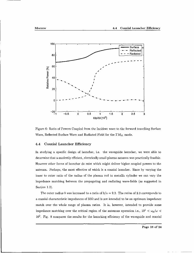
The results for the powers propagated and radiated are shown in Fig. 6, for a value of
v•w = 0.01. Where v is the collision frequency in the plasma and w the radian rf excitation
frequency 2 . The ratios of forward traveling (z directed) surface wave power, reflected power,
and radiated power to the incident power are given in percentage terms as a function of wp/w
over the usual range. The results show that the waveguide launcher is efficient in launching
the TMo1 surface wave and as the ratio wp/w increases the reflected power decreases.
4.3 Waveguide Launcher Efficiency
Fig. 7 shows the launching efficiency vs wp/w for the structure calculated based on the
"chopped" surface wave distribution. The Wiener-Hopf result is presented along with the
results obtained for the equivalent end aperture and Kirchhoff surface methods. The launch-
ing characteristics both exact and approximate have the same general behavior as shown in
Fig. 7. Closer inspection indicates the Wiener-Hopf consistently predicts higher launching
efficiency than those computed using the approximate methods. This feature if carried over
to a practical antenna design would deliver less losses. With regard performance bounds,
the approximate methods yield quite accurate results over the range 10-1 < Wp/W < 101.
Beyond this point the Wiener-Hopf results diverge from the approximate and this is thought
to be commensurate with the decrease in reflected power shown in Fig. 6.2these terms and their relationship to the plasma frequency wp and permittivity c, were described in the
interim report.
Page 15 of 24
Morrow 4.3 Waveguide Launcher Efficiency
End Aperture Radiation PatternI
0.9
0.8
0.7
M.6
o 0.5
S0.4
0.3
0.2
0.1
00 20 40 60 80 100 120 140 160 180
Angle [degs]
(a)
End Aperture Radiation Pattern1
0.9
0.8
0.7
- 0.6
005
00 0.4
0.3
0.2
0.1
0 20 40 60 80 100 120 140 160 180Angle [degs]
(b)
Figure 4: Radiation pattern due to fields on the radial surface of the cylindrical plasma
supporting the TMo1 mode for various wp/w ratios.(a) wp/w = 5.4 (b) wp/w = 9.0.
Page 16 of 24

Morrow 4.3 Waveguide Launcher Efficiency
End Aperture Radiation Pattern1
0.9
0.8
0.7
0.6
. 00.5
.0.4
0.3
0.2
0.1
0 20 40 60 80 100 120 140 160 180Angle [degs]
(c)
End Aperture Radiation Pattern
- O)p/03=105
0.9
0.8
0.7
0.6
0.5
0.4
0.3
0.2
0.1
0 20 40 60 80 100 120 140 160 180Angle [degs]
(d)
Figure 5: (Contn). Radiation pattern due to fields on the radial surface of the cylindrical
plasma supporting the TMol mode for various wp/w ratios.(c) Wp/W = 100 (d) wp/w = 1 x 10⁵ .
Page 17 of 24
Morrow 4.4 Coaxial Launcher Efficiency
100 -- Surface~Reflected|
80- - - - Radiated 1
S60 -,
0a- 40-
20 /
0-- ~ * -- - - - - - - - _ -
-20 p
-1 -0.5 0 0.5 1 1.5 2 2.5 3O)p/(,0 [lox]
Figure 6: Ratio of Powers Coupled from the Incident wave to the forward travelling Surface
Wave, Reflected Surface Wave and Radiated Field for the TM0 1 mode.
4.4 Coaxial Launcher Efficiency
In studying a specific design of launcher, i.e. the waveguide launcher, we were able to
determine that a modestly efficient, electrically small plasma antenna was practically feasible.
However other forms of launcher do exist which might deliver higher coupled powers to the
antenna. Perhaps, the most effective of which is a coaxial launcher. Since by varying the
inner to outer ratio of the radius of the plasma rod to metallic cylinder we can vary the
impedance matching between the propagating and radiating wave-fields (as suggested in
Section 1.2).
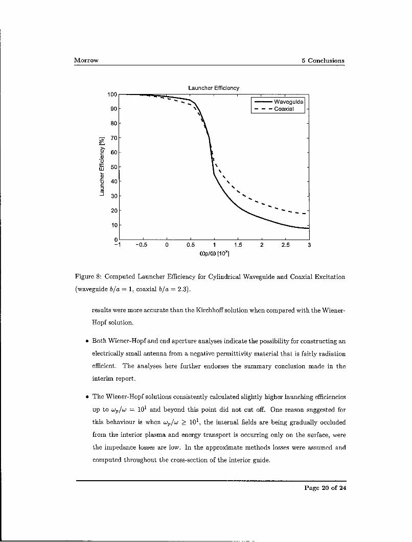
The outer radius b was increased to a ratio of b/a = 2.3. The ratios of 2.3 corresponds to
a coaxial characteristic impedances of 50Q and is not intended to be an optimum impedance
match over the whole range of plasma ratios. It is, however, intended to provide some
impedance matching over the critical region of the antennas operation i.e., 101 < Wp/W <
102. Fig. 8 compares the results for the launching efficiency of the waveguide and coaxial
Page 18 of 24

Morrow 5 Conclusions
Launcher Efficiency10 0 .. .i. . . .. ,, ,i
.... ..... -- End Aperture
90- -. '- - - Kirchhoff90 ""*,,•, Wiener-Hopf
80-
.70-
. 60 -
~550 -LU |
S40 - -
30 - I
I
20 ,
10 -
0ý-1 -0.5 0 0.5 1 1.5 2 2.5 3
O)p/(0 [1 0x]
Figure 7: Computed Launcher Efficiency for Cylindrical Waveguide Excitation with the
TMO1 mode using the End aperture, Kirchhoff and the Wiener-Hopf methods.
launchers. From the figure it is clear their is no significant improvement below Wp/W < 1,
beyond this region the launching efficiency is observed to increase slightly.
5 Conclusions
An antenna composed of a negative permittivity material and excited via a waveguide
launcher has been investigated mathematically. Two independent treatments of the problem
have been given; In the interim report two approximate analyses using the Kirchhoff and
equivalent end aperture method were applied and in this report an exact method, using
the Wiener-Hopf technique developed. The exact solution provides results with bounded
accuracy and are considered more rigorous.
* The launcher efficiency was computed for all three methods based upon the "chopped
surface wave" definition. On the approximate methods, the equivalent end aperture
Page 19 of 24
Morrow 5 Conclusions
Launcher Efficiency
Waveguide90\ Coaxial
80
70O
o 60
4 504 LU.
5 40 %30-"- 30 4.
20 "
10
0 p J I
-1 -0.5 0 0.5 1 1.5 2 2.5 3(op/(o [10x]
Figure 8: Computed Launcher Efficiency for Cylindrical Waveguide and Coaxial Excitation
(waveguide b/a = 1, coaxial b/a = 2.3).
results were more accurate than the Kirchhoff solution when compared with the Wiener-
Hopf solution.
" Both Wiener-Hopf and end aperture analyses indicate the possibility for constructing an
electrically small antenna from a negative permittivity material that is fairly radiation
efficient. The analyses here further endorses the summary conclusion made in the
interim report.
" The Wiener-Hopf solutions consistently calculated slightly higher launching efficiencies
up to wp/w = 101 and beyond this point did not cut off. One reason suggested for
this behaviour is when wp/w > 101, the internal fields are being gradually occluded
from the interior plasma and energy transport is occurring only on the surface, were
the impedance losses are low. In the approximate methods losses were assumed and
computed throughout the cross-section of the interior guide.
Page 20 of 24

Morrow 6 Recommendations for Future Work
a For completeness a coaxial launcher design was also investigated. This was demon-
strated to provide more effective matching of the launcher to the plasma geometry.
The results indicate that this could enhance launcher efficiency by another 10% for
wp/w > 1. As the plasma ratio increases the radiation patterns followed the waveguide
behaviour.
6 Recommendations for Future Work
The following recommendations are made;
e It would seem appropriate to experimentally substantiate some of the claims made in
the conclusions. This could be achieved via another cooperative research program.
Reported experiments with negative permittivity antennas have concentrated on free-
space plasmas [15, 16]. However, these antenna suffers from high losses and present
many practical implementation issues. The idea proposed here is to construct a passive
plasma analogue material3 , excite it using the coaxial launcher and characterise its
performance. The intended operating band would be in the 20-1000 MHz frequency
spectrum were compact, lightweight wideband aerials for mobile communications are
often required. Transmit power would be restricted to a few 10's of Watts. A single
antenna is suggested were the engineering novelty should be to provide an antenna
much more compact than a conventional A/4 or A/2 whip aerial.
"* It is unlikely that a single antenna will be suitable to cover the whole frequency spec-
trum mentioned above. Therefore, I should wish to extent the research effort to either
compact clustered or active plasma analogue variants. This latter effort would address
the challenge of achieving more bandwidth and/or more gain. AFRL should advise
if such a study is relevant to their current requirements and how best to initiate the
study.
"* One other attendant research issue is the antenna operation. The radiation from any
electrically small HF antenna, which is dipole like, will be effected by the presence of3 Some interesting papers were highlighted in the Interim Report that point to useful passive negative
permittivity materials that may be suitable for antenna application.
Page 21 of 24

Morrow 7 Acknowledgements
the equipment operator, the ground and surrounding environment. It would also be
appropriate to investigate experimentally, or otherwise, the effect on radiation pattern
and antenna system losses in the vicinity of dielectric and conductive objects.
a To make appropriate conference and journal publications based on this work and citing
the EOARD sponsorship. It is noted there has been a recent call for a special issue of
the IEE on metamaterials and novel antennas.
-oo0oo--
7 Acknowledgements
The author would like to acknowledge Profs. J. R. James and J. S. Dahele for many stim-
ulating and interesting conversations on many aspects of the theory, design and practice
with dielectric and material loaded antenna structures. I should particularly like to thank
Prof. Jash Dahele for the generous grift of his collection of electromagnetic texts and re-
search papers. I also should like to personally congratulate Jash on his award of Emeritus
Professor.
Page 22 of 24

Morrow REFERENCES
8 References
[1] R. Chatterjee. Dielectric and Dielectric-Loaded Antennas. Research Studies Press Ltd.,
Wiley and Sons, 1985.
[2] C. Salema, C. Fernandes, and R. K. Jha. Solid Dielectric Horn Antennas. Artech House,
1998.
[3] K. Man Luk and K. Leung. Dielectric Resonator Antennas. Research Studies Press
Ltd., 2003.
[4] J. R. Wait. Electromagnetics and Plasmas. Holt, Rinehart and Winston, 1968. Chapter
5.
[5] J. Brown. Some theoretical results for surface wave launcher. IEE Trans. on Antennas
and Propagat., pages pp. 169-174, December, 1959.
[6] I. L. Morrow. Interim progress report: Launching of electromagnetic surface waves
on axial cylindrical reactive surfaces with negative permittivity. Technical Report
DAPS/ILM/113/2005, Cranfield University, RMCS, Shrivenham, Swindon, Wilts. UK,
SN6 8LA, June 2005.
[7] R. E. Collins. Field Theory of Guided Waves. IEEE Press, 2nd edition edition, 1991.
Chapter 11.
[8] C. M. Angulo and W. Chang. The excitation of a dielectric rod by a cylindrical waveg-
uide. IRE Trans. on Microwaves Theory and Techniques, pages pp. 389-393, Oct. 1958.
[9] D. S. Jones. Acoustic and Electromagnetic Waves. Oxford University Press, 1986.
[10] P. M. Morse and H. Feshback. Methods of Theoretical Physics. McGraw-Hill, 1953.
[11] J. A. Stratton. Electomagnetic Theory. McGraw-Hill, 1941.
[12] H. M. Barlow and J. Brown. Radio Surface Waves. Oxford University Press, London,
1962.
[13] L. B. Felsen and N. Marcuvitz. Radiation and Scattering of Waves. IEEE Press, 1994.
Page 23 of 24

Morrow 8 References
[14] Abramowitz and Stegun. Handbook of Mathematical Functions. Dover Publications,
Inc. New York, June 1964.
[15] G. G. Borg and J. H. Harris. Application of plasma columns to radio frequency antennas.
Applied Physics letters, 74:3272-3274, 1999.
[16] G. G. Borg, J. H. Harris, N. M. Martin, D. Thorncraft, R. Miliken, D. G. Mijak,
B. Kwan, T. Ng, and J. Kircher. Plasmas as antennas: Theory, experiment and appli-
cations. Physics of Plasmas, 7:2198-2202, 2000.
Page 24 of 24