crary tile pro: stringer trailer owners manual manual stringer trailer...crary tile pro: stringer...
TRANSCRIPT

Crary Tile Pro: Stringer Trailer Owners Manual
Crary Agricultural Solutions, LLC October 2013


Tile Pro Crary Agricultural Solutions, LLC
P.O. Box 237 Morgan, MN 56266
507-249-3176 507-249-3146 FAX
Website: www.crarytilepro.com
Questions?
Kenton Johnson 1-507-430-5729 [email protected]
GPS/Laser controls technical support.
Wayne Weber 1-507-828-4548 [email protected]
Plow setup, general plow questions.
Stan Isfeld, Sales and Support 1-507-430-7677 [email protected]
Crary Agricultural Solutions, LLC

L IMITED WARRANTY This warranty applies to all Crary Tile Pro equipment manufactured by Crary Agricul-tural Solutions, LLC (Crary). Crary warrants to the original owner of each new Crary Tile Pro product to be free from defects in material and workmanship, under normal use and service. The warranty shall extend as shown below from date of delivery. The product is warranted to the original owner as evidenced by a completed warranty registration on file at Crary and is non-transferable beyond the initial purchaser.
Product Warranty Length Crary Tile Pro Plow 1 year Crary Tile Pro Trailers 1 year Crary Tile Pro Spool/Carriers 1 year
THE WARRANTY REGISTRATION MUST BE COMPLETED AND RETURNED TO CRARY WITHIN 10 DAYS OF DELIVERY OF THE PRODUCT TO THE ORIGINAL OWNER OR THE WARRANTY WILL BE VOID. In the event of a failure, return the product, at your cost, along with proof of purchase to the selling Crary dealer. Crary will, at its option, repair or replace any parts found to be defective in material or workmanship. Warranty on any repairs will not extend beyond the product warranty. Repair or attempted repair by anyone other than a Crary dealer as well as subsequent failure or damage that may occur as a result of that work will not be paid under this warranty. Crary does not warrant replacement components not manufac-tured or sold by Crary. This warranty applies only to parts or components that are defective in material or work-manship. This warranty does not cover wear items including but not limited to knife tips, ground engaging components, bearings, tires etc.
This warranty does not cover normal maintenance, service or adjustments.
This warranty does not cover depreciation or damage due to misuse, negligence, accident or improper maintenance.
This warranty does not cover damage due to improper setup, installation or adjust-ment.
This warranty does not cover damage due to unauthorized modifications of the product.
This warranty does not cover damage, deemed by a Crary representative, due to excessive stress or by exceeding the products ability and manufacturer’s intended use of the product.

L IMITED WARRANTY Any warranty of any grade control, hydraulic components or guidance components sold on, or installed on, Crary products are subject to the original manufacture warranty and are not the responsibility of Crary.
Crary is not liable for any property damage, personal injury or death resulting from the unauthorized modification or alteration of a Crary product or from the owner’s failure to assemble, install, maintain or operate the product in accor-dance with the provisions of the Owner’s manual. Crary is not liable for any damages or expenses incurred on the host machine or on any non Crary equip-ment through the use of these products. New replacement parts made by Crary carry a full 90-day, parts only, warranty from the date they are purchased. Crary is not liable for indirect, incidental or consequential damages or injuries including but not limited to loss of crops, loss of profits, rental of substitute equipment or other commercial loss. This warranty gives you specific legal rights. You may have other rights that may vary from area to area. Crary makes no warranties, representations or promises, expressed or implied as to the performance of its products other than those set forth in this warranty. Neither the dealer nor any other person has any authority to make any represen-tations, warranties or promises on behalf of Crary or to modify the terms or limi-tations of this warranty in any way. Crary, at its discretion, may periodically offer limited, written enhancements to this warranty. CRARY AGRICULTURAL SOLUTIONS, LLC IS A WHOLLY OWNED SUB-SIDIARY OF CRARY INDUSTRIES, INC AND RESERVES THE RIGHT TO CHANGE THE DESIGN AND/OR SPECIFICATIONS OF ITS PRODUCTS AND WARRANTIES AT ANY TIME WITHOUT OBLIGATION TO PREVI-OUS PURCHASERS OF ITS PRODUCTS.


You really have no idea what is under the ground.
It’s a free service and could save
YOUR LIFE!
Call 811 FIRST.
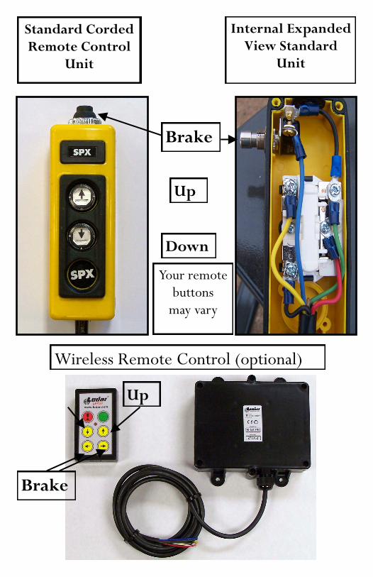
Standard Corded Remote Control
Unit
Internal Expanded View Standard
Unit
Up
Wireless Remote Control (optional)
Brake
Down
Up
Brake
Your remote buttons
may vary

Stringer Trailer Brake Adjustment Port
Expanded view showing star adjuster

When making this adjustment the table top should be positioned so that the adjustment port is facing the
front side of the trailer.
Brake Adjustment
To adjust brake to more tension push the star adjuster down

To adjust brake to less tension push the star adjustment up

Adjusting the pump
To adjust the flow in the hydraulic pump to more pressure turn screw 1/4 turn at a time clockwise and test. Do this until desired pressure has been obtained To adjust pressure to less pressure turn 1/4 turn counter clockwise. Do this until desired pressure has been obtained.

Filling the pump
Hydraulic Pump refill port. Fill with Dexron transmission fluid. It’s best to leave about an inch of space from the bottom of the neck of the port to al-
low for any overfill seepage.

Make sure that the pin is completely inserted through the mounting holes, and is seen extending
through the bottom hole.
Securing the Jack

Securing the table top for safe transporting.
Make sure that the table top lock at the back of the trailer is in the up posi-tion, and the pin is com-pletely through the hole and locked
The wing should be folded under, and the locking handle in the inserted and locked position.
Finally, secure the wings with the locking pin. Make sure that it is completely inserted, and in the locked posi-

Yellow - Up 12 Volt
Up Signal
Red
12 Volt Supply
White
Black– Ground
Green -Down Blue/Brown—Brake
Wireless remote Wiring Configuration For Hydraulic Pump

Yellow- Up
Black = Power from Alternator of truck/tractor
Green - Power to Pendant
Black - Down
Red –Pump Power
Wiring Configuration For Hydraulic Pump

How to reset the Lodar Transmitter (Handheld) unit. This procedure should correct any communication issues that arise with your remote control unit.
**Reset may be required anytime power is lost to transmitter or receiver unit.
1. Remove the battery from the handheld transmitter. 2. Remove power from the receiver unit. 3. Depress and hold “F1 = Down” and “F2 = Up” on the
transmitter as you reinstall the 9VDC battery. 4. Hold and then release both “F1” and “F2” after 3 to 5
seconds, the red LED will light up. 5. Look for a flash pattern from 1 to 4 flashes separated
by a pause on the red LED. 6. If the # of flashes counted was 2, then depress “F2”
button below the green button 3 time (5 -2 = 3) 7. After you pressed the “F2” button (5 - #flashes = X
times needed to press “F2”) you should see the red LED flash 5 times.
8. If you see the 5 flash sequence followed by a pause, you have correctly entered the correct # of missing flashes. Press the “Red” button to accept the reset.
9. If you did not end up with 5 flashes, repeat steps 1 thru 8 again.
10.Uses care to see that the 9VDC battery stays installed once you start the reset process.
11.The transmitter and receiver now need to be re-registered. Follow the Transmitter on the following page.


Trailer Light Wiring
Yellow (blinker) Brown (running)
Green (blinker) Brown (running)
7 Pin Wiring Diagram For Tow Vehicle

There are 5 zerks on each trailer for the application of grease. One at the back of the trailer, and the other 4 lo-cated along the bottom of the axel.
Zerk Locations

If the table does not tilt up or down
Check the battery for a charge.
Make sure that the connec-tions on the battery are tight and there
is good contact
If the table brake does not engage.
Check the battery for a charge, and the connections. (It also takes
about 1/3 revolution for brake to function).
If there is no click when the brake button is
pressed.
Check for power to the drum at the drum with a circuit tester.
(You may need to remove the wire nuts to check).
If the brake button is pressed and there is a click.
Adjust the brake at the brake adjustment port.
If the table doesn’t want go up or down but the motor pulls down
OR The table raises but wont lower or vise versa.
OR The solenoid seems to be stuck.
Take a jumper wire and hook to positive terminal or both and
click solenoids on pump several times on both sides yellow and green wire. Do this without running the pump
Troubleshooting

MORE THAN 3”
LESS THAN 3.25”
TABLE TOP

Brake Assembly

Brake Parts List

Wheel Bearing Parts List and Maintenance
Part Part (OEM#) Wheel 11L15 Dust Cap 103969 Cotter Pin 5957 Nut 103289 Washer 104581 Outside Bearing 104082 Hub 106749 Hub Seal 103953 Inside Bearing 106750
Instructions
Pack the bearing with a bearing packer, by placing the bearing in a packer small side down. Push until the grease comes through the bearing. Remove bearing packer, smear face of bearing and race in hub with grease. Replace all components in reverse order of above. When packing by hand, place grease in palm of hand, and push from the large side of the bearing into grease, repeat-edly until grease comes through to small side of bearing. Smear face of bearing and race in hum with grease, then replace all components in reverse order of above.
