crate bv-60h, bv-120h user manual
DESCRIPTION
User Manual for Tube Amplifiers "Crate BV-60 & BV-120"TRANSCRIPT

User’s Guide
for the
BV-60H / BV-120H
All TubeGuitar Amplifiers
by
Musician-Made in the U.S.A.
Congratulations!Your love of performing and driving ambition to be the best have brought you to a turning point in your musical
career: the incredible BV-60H/BV-120H Professional Series guitar amplifier. An all-tube powerhouse of an amplifi-er designed to take you to the top and keep you there.
We know something about you: we know you were never impressed with those "toys" that some of your friendscalled amplifiers. We know you were holding out until someone offered you an American-made, affordable pieceof professional equipment you could really sink your teeth into. A serious amplifier, designed for a serious musi-cian: an amp with the sounds you've always looked for, the power you've always dreamed about, and the reliabil-ity you know you'll need. And all with a name you know you can trust: CRATE.
Your BV-60H/120H was designed by musicians, and built using only the best components. Extensive testing atthe hands and ears of skilled technicians and musicians insures you that this amplifier is the absolute best it can be.
In order to get the most out of your new amplifier, we strongly urge you to read this user’s guide before youbegin playing.
And thank you for choosing
Contents:Introduction . . . . . . . . . . . . . . . . . . . . . . . . . . . . . . . . . . . . . . . . . . . .3
Features . . . . . . . . . . . . . . . . . . . . . . . . . . . . . . . . . . . . . . . . . . . . . .3
The Front Panel . . . . . . . . . . . . . . . . . . . . . . . . . . . . . . . . . . . . . . . . .4
The Rear Panel . . . . . . . . . . . . . . . . . . . . . . . . . . . . . . . . . . . . . . . . .5
Important Information About Tubes and Tube Products
A Brief History Of The Tube . . . . . . . . . . . . . . . . . . . . . . . . . . . . . .6
Tube Types And Usage . . . . . . . . . . . . . . . . . . . . . . . . . . . . . . . . .6
The Nature Of Tubes: Why (And When) To Replace Them . . . . . . .7
The Importance Of Proper Biasing . . . . . . . . . . . . . . . . . . . . . . . . .7
Survival Tips For Tube Amplifiers . . . . . . . . . . . . . . . . . . . . . . . . . .8
Some Suggested Settings . . . . . . . . . . . . . . . . . . . . . . . . . . . . . . . . .9
System Block Diagram . . . . . . . . . . . . . . . . . . . . . . . . . . . . . . . . . . .10
Technical Specifications . . . . . . . . . . . . . . . . . . . . . . . . . . .back cover
2
IMPORTANT WARNING: Whenever stacking speaker cabinets of any kind, place them ONLY on a levelsurface! NEVER stack cabinets on a surface with more than a five degree incline since tipping could
occur, possibly causing serious injuries!
IMPORTANT SAFETY INSTRUCTIONS• READ, FOLLOW, HEED, AND KEEP ALL INSTRUCTIONS AND WARNINGS.
• DO NOT OPERATE NEAR ANY HEAT SOURCE AND DO NOT BLOCK ANY VENTILATION OPENINGS ON THIS APPARATUS. FOR PROPER OPERATION, THIS UNIT REQUIRES 3”(75CM) OF WELL VENTILATED SPACE AROUND HEATSINKS AND OTHER AIR FLOW PROVISIONS IN THE CABINET.
• DO NOT USE THIS APPARATUS NEAR SPLASHING, FALLING, SPRAYING, OR STANDING LIQUIDS.
• CLEAN ONLY WITH LINT-FREE DAMP CLOTH AND DO NOT USE CLEANING AGENTS.
• ONLY CONNECT POWER CORD TO A POLARIZED, SAFETY GROUNDED OUTLET WIRED TO CURRENT ELECTRICAL CODES AND COMPATIBLE WITH VOLTAGE, POWER, ANDFREQUENCY REQUIREMENTS STATED ON THE REAR PANEL OF THE APPARATUS.
• PROTECT THE POWER CORD FROM DAMAGE DUE TO BEING WALKED ON, PINCHED, OR STRAINED.
• UNPLUG THE APPARATUS DURING LIGHTNING STORMS OR WHEN UNUSED FOR LONG PERIODS OF TIME.
• ONLY USE ATTACHMENTS, ACCESSORIES, STANDS, OR BRACKETS SPECIFIED BY THE MANUFACTURER FOR SAFE OPERATION AND TO AVOID INJURY.
• WARNING: TO REDUCE THE RISK OF ELECTRIC SHOCK OR FIRE, DO NOT EXPOSE THIS UNIT TO RAIN OR MOISTURE.
• SERVICE MUST BE PERFORMED BY QUALIFIED PERSONNEL.
• OUR AMPLIFIERS ARE CAPABLE OF PRODUCING HIGH SOUND PRESSURE LEVELS. CONTINUED EXPOSURE TO HIGH SOUND PRESSURE LEVELS CAN CAUSE PERMA-NENT HEARING IMPAIRMENT OR LOSS. USER CAUTION IS ADVISED AND EAR PROTECTION IS RECOMMENDED IF UNIT IS OPERATED AT HIGH VOLUME.
CAUTIONRISK OF ELECTRIC SHOCK
DO NOT OPEN
WARNING: TO REDUCE THE RISK OF FIRE OR ELECTRIC SHOCK, DO NOT EXPOSETHIS APPARATUS TO RAIN OR MOISTURE. TO REDUCE THE RISK OF ELECTRICSHOCK, DO NOT REMOVE COVER. NO USER-SERVICEABLE PARTS INSIDE. REFERSERVICING TO QUALIFIED SERVICE PERSONNEL.
PRECAUCIONRIESGO DE CORRIENTAZO
NO ABRA
PRECAUCION: PARA REDUCIR EL RIESGO DE INCENDIOS O DESCARGAS ELECTRICAS, NO PER-MITA QUE ESTE APARATO QUEDE EXPUESTO A LA LLUVIA O LA HUMEDAD. PARA DISMINUOIR ELRIESGO DE CORRIENTAZO. NO ABRA LA CUBIERTA. NO HAY PIEZAS ADENTRO QUE EL USARIOPUEDO REPARAR DEJE TODO MANTENIMIENTO A LOS TECHNICOS CALIFICADOS.
ATTENTIONRISQUE D'ELECTROCUTION
NE PAS OUVRIR
ATTENTION: PROTÉGEZ CET APPAREIL DE LA PLUIE ET DE L'HUMIDITÉ AFIN D'ÉVITER TOUTRISQUE D'INCENDIE OU D'ÉLECTROCUTION. POUR REDUIRE D'ELECTROCUTION NE PAS ENLEVERLE COUVERCLE. AUCUNE PIECE INTERNE N'EST REPRABLE PAR L'UTILISATEUR. POUR TOUTEREPARATION, S'ADRESSER A UN TECHNICIEN QUALIFIE.
"IT IS NECESSARY FOR THE USER TO REFER TO THE INSTRUCTION MANUAL"
“ES NECESARIO QUE EL USUARIO SE REFIERA AL MANUAL DE INSTRUCCIONES.”
"REFERREZ-VOUS AU MANUAL D'UTILISATION"
EXPLANATION OF GRAPHICAL SYMBOLS:
EXPLICACION DE SIMBOLOS GRAFICOS:
EXPLICATION DES SYMBÔLES GRAPHIQUES:
"DANGEROUS VOLTAGE"
“VOLTAJE PELIGROSO”
"DANGER HAUTE TENSION"
= =
BV-60H / BV-120H All Tube Guitar Amplifiers
Introduction:The BV-60H/120H are all-tube, feature-packed professional stage performers' amplifiers. Rugged con-
struction, reliable American craftsmanship and two powerful channels of pure tube power are some of thetrademarks of these new and impressive pieces of musician's equipment. Both amplifiers feature two dis-tinctly different 12AX7 tube-driven channels: one with classic tube rhythm sounds and one offering you someof the finest lead and overdrive sounds of any stock amplifier.
Each channel features an all-tube preamp section with separate reverb level controls and three bands ofequalization for total tone control. The master Presence control lets you custom tailor the sound of your gui-tar to suit your particular needs. The effects loop can be quickly bypassed via the front panel switch or anoptional footswitch and features a switchable “pad” for use with either floor pedals or rack-mounted effects.
The Line Out signal is tapped directly from the speaker outputs, then attenuated and frequency-compen-sated to replicate the sound of a miked speaker cabinet. Dual speaker jacks and an impedance selectorswitch allow the use of multiple cabinets totalling 8 or 16 ohms. The BV-60H packs a solid 50 watts of out-put power; the 120H a whopping 100 watts.
Features:Here's a quick overview of the BV-60H/120H's features and controls. Additional information can
be found on the pages indicated.
• All-Tube Preamp and Power Amp: Classic tube sounds with Crate’s legendary performance andreliability.
• Two Completely Separate Channels: Independent level, tone and reverb controls (page 4).
• Presence Control: Provides even greater tone control and flexibility by allowing you to vary theupper harmonics of your guitar (page 4).
• Footswitch Control: Remote channel selection and Effects Loop On/Off is available through theuse of an optional two-button footswitch (such as Crate’s CFP-2) (page 5).
• Switchable Effects Loop with Pad: Footswitch or front panel button controlled, the externaleffects loop can be switched in or out with ease. A switchable pad provides optimum performancefrom line-level rack mounted effects as well as floor-dwelling foot pedals (pages 4,5).
• Impedance Selector Switch: Proper impedance matching is essential for optimum performanceand life expectancy of a tube amplifier. These amps allow the use of 8 or 16 ohm speaker config-urations (page 5).
• Line Out Jack: Taken directly from the speaker output jacks, the Line Out signal is frequencycompensated to sound like a “miked” speaker cabinet. Use this jack to connect to the house mix-ing board, a recording console or another performer’s powered monitor (page 5).
• DC Filament Supply: The first preamp tube has a DC filament supply for reduced hum.
• High Cosmetic Appeal and Stage Presence: The unique cosmetics of the BV-60H/120H serveas a tribute to your good taste in musical equipment.
• Musician Made in the U.S.A.
3
BV-60H / BV-120H All Tube Guitar Amplifiers
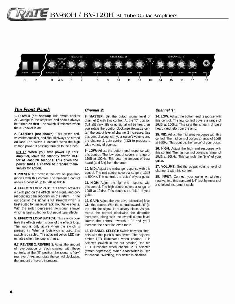
The Front Panel:1. POWER (not shown): This switch appliesAC voltage to the amplifier, and should alwaysbe turned on first. The switch illuminates whenthe AC power is on.
2. STANDBY (not shown): This switch acti-vates the amplifier, and should always be turnedon last. The switch illuminates when the highvoltage power is passing through to the tubes.
NOTE: When you first power up thisamplifier, leave the Standby switch OFFfor at least 20 seconds. This gives thepower tubes a chance to prepare them-selves for action.
3. PRESENCE: Increase the level of upper har-monics with this control. The presence controlallows a boost of up to 5dB at 10kHz.
4. EFFECTS LOOP PAD: This switch activatesa 12dB pad on the effects send signal and cor-responding gain recovery on the return. In theout position the signal is full strength which isbest suited for line level rack mountable effects.With the switch depressed the signal is lowerwhich is best suited for foot pedal type effects.
5. EFFECTS LOOP SWITCH: This switch con-trols the effects return signal of the effects loop.The loop is only active when the switch ispressed in. When a footswitch is used, thisswitch is disabled. The adjacent yellow LED illu-minates when the loop is in use.
6,7. REVERB 2, REVERB 1: Adjust the amountof reverberation on each channel with thesecontrols: at the "0" position the signal is "dry"(no reverb). As you rotate the control clockwise,the amount of reverb increases.
Channel 2:
8. MASTER: Set the output signal level ofchannel 2 with this control. At the "0" position(full left) very little or no signal will be heard; asyou rotate the control clockwise (towards cen-ter) the output level of channel 2 increases. Usethis control along with your guitar's volume andthe channel 2 gain control (#12) to produce awide variety of sounds.
9. LOW: Adjust the bottom end response withthis control. The low control covers a range of15dB at 100Hz. This sets the amount of bassheard (and felt) from the amp.
10. MID: Adjust the midrange response with thiscontrol. The mid control covers a range of 13dBat 500Hz. This controls the “voice” of your guitar.
11. HIGH: Adjust the high end response withthis control. The high control covers a range of10dB at 10kHz. This controls the “bite” of yourguitar.
12. GAIN: Adjust the overdrive (distortion) levelwith this control. With the control towards “0” (tothe left) the signal is relatively clean. As yourotate the control clockwise the distortionincreases, along with the overall output level.Rotate the control towards “10” and you’llincrease the distortion even more.
13. CHANNEL SELECT: Switch between chan-nels with this push-button switch. The adjacentamber LED illuminates when channel 1 isselected (switch in the out position), the redLED illuminates when channel 2 is selected(switch depressed). When a footswitch is usedfor channel switching, this switch is disabled.
Channel 1:
14. LOW: Adjust the bottom end response withthis control. The low control covers a range of16dB at 100Hz. This sets the amount of bassheard (and felt) from the amp.
15. MID: Adjust the midrange response with thiscontrol. The mid control covers a range of 20dBat 300Hz. This controls the “voice” of your guitar.
16. HIGH: Adjust the high end response withthis control. The high control covers a range of10dB at 10kHz. This controls the “bite” of yourguitar.
17. VOLUME: Set the output volume level ofchannel 1 with this control.
18. INPUT: Connect your guitar or wirelessreceiver into this standard 1/4" jack by means ofa shielded instrument cable.
4
INPUTVOLUMELOW MID HIGHGAINHIGHMIDLOWVOLUMELEVEL1
LEVEL2
PRESENCEPOWER STANDBY
EFFECTS LOOPEFFECTS LOOPPAD (12dB)AD (12dB)
CHANNELCHANNELSELECTSELECT
EFFECTS LOOPEFFECTS LOOP
ONON OFFOFF 2 1
O
-5 +5
O
-5 +5
O
-5 +5
O
-5 +5
O
-5 +5
O
-5 +5
CHANNEL 1CHANNEL 2REVERB
O
1
O1
2
3
4 5 6
7
8
9
O
1
O1
2
3
4 5 6
7
8
9
O
1
O1
2
3
4 5 6
7
8
9
O
1
O1
2
3
4 5 6
7
8
9
O
1
O1
2
3
4 5 6
7
8
9
O
1
O1
2
3
4 5 6
7
8
9
1 2 3 8 9 10 11 12 13 14 15 16 17 186 754
BV-60H / BV-120H All Tube Guitar Amplifiers
5
125VAC, 50/60Hz T5A SLO-BLO250VAC, 50/60Hz T2.5A SLO-BLO
AC LINE IN
AVIS:RISQUE DE CHOC ELECTRIQUE. NE PAS OUVRIR
CAUTIONRISK OF ELECTRIC SHOCK
DO NOT OPEN
WARNING: TO REDUCE THE RISK OF FIRE OR ELECTRICAL SHOCK, SO NOT EXPOSE THIS EQUIP-MENT TO RAIN OR MOISTURE.
M a d e i n t h e U . S . A . b y • S L M E L E C T R O N I C S1 4 0 0 F e r g u s o n A v e . • S t . L o u i s , M O . 6 3 1 3 3
MAIN(USE FIRST)
EXT.
SPEAKERS100 WATTS RMS
LINE OUT
IMPEDANCESELECTOR
8 16
SEND
TIP = CHANNEL SELECTRING = EFFECTS LOOP
SLEEVE = GROUND
RETURN
EFFECTSLOOP FOOTSWITCH
RT S TS
R
272625242321 2219 20
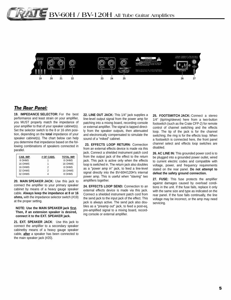
The Rear Panel:19. IMPEDANCE SELECTOR: For the bestperformance and least strain on your amplifier,you MUST properly match the impedance ofyour amplifier to that of your speaker cabinet(s).Set the selector switch to the 8 or 16 ohm posi-tion, depending on the total impedance of yourspeaker cabinet(s). The chart below can helpyou determine that impedance based on the fol-lowing combinations of speakers connected inparallel.
CAB. IMP. # OF CABS. TOTAL IMP.8 OHMS 1 8 OHMS16 OHMS 1 16 OHMS16 OHMS 2 8 OHMS32 OHMS 2 16 OHMS32 OHMS 4 8 OHMS
20. MAIN SPEAKER JACK: Use this jack toconnect the amplifier to your primary speakercabinet by means of a heavy gauge speakercable. Always keep the impedance at 8 or 16ohms, with the impedance selector switch (#19)at the proper setting.
NOTE: Use the MAIN SPEAKER jack first.Then, if an extension speaker is desired,connect it to the EXT. SPEAKER jack.
21. EXT. SPEAKER JACK: Use this jack toconnect the amplifier to a secondary speakercabinetby means of a heavy gauge speakercable, after a speaker has been connected tothe main speaker jack (#20).
22. LINE OUT JACK: This 1/4” jack supplies aline-level output signal from the power amp forpatching into a mixing board, recording consoleor external amplifier. The signal is tapped direct-ly from the speaker outputs, then attenuatedand electronically compensated to simulate thesound of a “miked” cabinet.
23. EFFECTS LOOP RETURN: Connectionfrom an external effects device is made via thisjack. Connect a shielded instrument patch cordfrom the output jack of the effect to the returnjack. This jack is active only when the effectsloop is switched in. The return jack also doublesas a "power amp in" jack, to feed a line-levelsignal directly into the BV-60H/120H's internalpower amp. This is useful when "slaving" twoamplifiers together.
24. EFFECTS LOOP SEND: Connection to anexternal effects device is made via this jack.Connect a shielded instrument patch cord fromthe send jack to the input jack of the effect. Thisjack is always active. The send jack also dou-bles as a "preamp out" jack, to feed a post-eq,pre-amplified signal to a mixing board, record-ing console or external amplifier.
25. FOOTSWITCH JACK: Connect a stereo1/4” (tip/ring/sleeve) here from a two-buttonfootswitch (such as the Crate CFP-2) for remotecontrol of channel switching and the effectsloop. The tip of the jack is for the channelswitching; the ring is for the effects loop. Whena footswitch is connected here, the front panelchannel select and effects loop switches aredisabled.
26. AC LINE IN: This grounded power cord is tobe plugged into a grounded power outlet, wiredto current electric codes and compatible withvoltage, power, and frequency requirementsstated on the rear panel. Do not attempt todefeat the safety ground connection.
27. FUSE: This fuse protects the amplifieragainst damages caused by overload condi-tions in the unit. If the fuse fails, replace it onlywith the same size and type as indicated on therear panel. If the fuse fails continually, the linevoltage may be incorrect, or the amp may needservicing.
BV-60H / BV-120H All Tube Guitar Amplifiers
Important Information About Tubes And Tube Products:
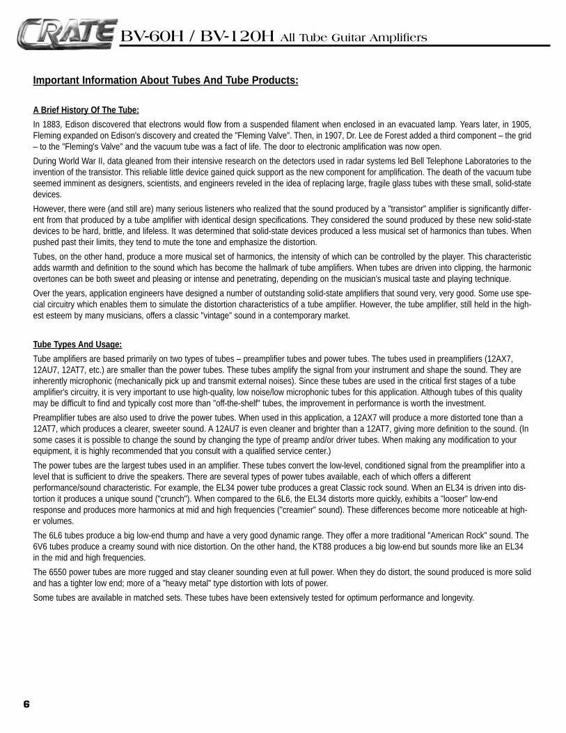
A Brief History Of The Tube:
In 1883, Edison discovered that electrons would flow from a suspended filament when enclosed in an evacuated lamp. Years later, in 1905,Fleming expanded on Edison's discovery and created the "Fleming Valve". Then, in 1907, Dr. Lee de Forest added a third component – the grid– to the "Fleming's Valve" and the vacuum tube was a fact of life. The door to electronic amplification was now open.
During World War II, data gleaned from their intensive research on the detectors used in radar systems led Bell Telephone Laboratories to theinvention of the transistor. This reliable little device gained quick support as the new component for amplification. The death of the vacuum tubeseemed imminent as designers, scientists, and engineers reveled in the idea of replacing large, fragile glass tubes with these small, solid-statedevices.
However, there were (and still are) many serious listeners who realized that the sound produced by a "transistor" amplifier is significantly differ-ent from that produced by a tube amplifier with identical design specifications. They considered the sound produced by these new solid-statedevices to be hard, brittle, and lifeless. It was determined that solid-state devices produced a less musical set of harmonics than tubes. Whenpushed past their limits, they tend to mute the tone and emphasize the distortion.
Tubes, on the other hand, produce a more musical set of harmonics, the intensity of which can be controlled by the player. This characteristicadds warmth and definition to the sound which has become the hallmark of tube amplifiers. When tubes are driven into clipping, the harmonicovertones can be both sweet and pleasing or intense and penetrating, depending on the musician’s musical taste and playing technique.
Over the years, application engineers have designed a number of outstanding solid-state amplifiers that sound very, very good. Some use spe-cial circuitry which enables them to simulate the distortion characteristics of a tube amplifier. However, the tube amplifier, still held in the high-est esteem by many musicians, offers a classic "vintage" sound in a contemporary market.
Tube Types And Usage:
Tube amplifiers are based primarily on two types of tubes – preamplifier tubes and power tubes. The tubes used in preamplifiers (12AX7,12AU7, 12AT7, etc.) are smaller than the power tubes. These tubes amplify the signal from your instrument and shape the sound. They areinherently microphonic (mechanically pick up and transmit external noises). Since these tubes are used in the critical first stages of a tubeamplifier's circuitry, it is very important to use high-quality, low noise/low microphonic tubes for this application. Although tubes of this qualitymay be difficult to find and typically cost more than "off-the-shelf" tubes, the improvement in performance is worth the investment.
Preamplifier tubes are also used to drive the power tubes. When used in this application, a 12AX7 will produce a more distorted tone than a12AT7, which produces a clearer, sweeter sound. A 12AU7 is even cleaner and brighter than a 12AT7, giving more definition to the sound. (Insome cases it is possible to change the sound by changing the type of preamp and/or driver tubes. When making any modification to yourequipment, it is highly recommended that you consult with a qualified service center.)
The power tubes are the largest tubes used in an amplifier. These tubes convert the low-level, conditioned signal from the preamplifier into alevel that is sufficient to drive the speakers. There are several types of power tubes available, each of which offers a differentperformance/sound characteristic. For example, the EL34 power tube produces a great Classic rock sound. When an EL34 is driven into dis-tortion it produces a unique sound ("crunch"). When compared to the 6L6, the EL34 distorts more quickly, exhibits a "looser" low-endresponse and produces more harmonics at mid and high frequencies ("creamier" sound). These differences become more noticeable at high-er volumes.
The 6L6 tubes produce a big low-end thump and have a very good dynamic range. They offer a more traditional "American Rock" sound. The6V6 tubes produce a creamy sound with nice distortion. On the other hand, the KT88 produces a big low-end but sounds more like an EL34in the mid and high frequencies.
The 6550 power tubes are more rugged and stay cleaner sounding even at full power. When they do distort, the sound produced is more solidand has a tighter low end; more of a "heavy metal" type distortion with lots of power.
Some tubes are available in matched sets. These tubes have been extensively tested for optimum performance and longevity.
6
BV-60H / BV-120H All Tube Guitar Amplifiers
Important Information About Tubes And Tube Products (Continued):
The Nature Of Tubes: Why (And When) To Replace Them:
Tubes are made up of a number of fragile mechanical components that are vacuum-sealed in a glass envelope or bubble. The tube's longevi-ty is based on a number of factors which include how hard and often the amplifier is played, vibration from the speakers, road travel, repeatedset up and tear down, etc.
Any time you notice a change in your amplifier's performance, check the tubes first.
If it's been a while since the tubes were replaced and the sound from your amplifier lacks punch, fades in and out, loses highs or lows or pro-duces unusual sounds, the power tubes probably need to be replaced. If your amplifier squeals, makes noise, loses gain, starts to hum, lacks"sensitivity", or feels as if it is working against you, the preamplifier tubes may need to be replaced.
The power tubes are subjected to considerably more stress than the preamplifier tubes. Consequently, they almost always fail/degrade first. Ifdeteriorating power tubes aren't replaced they will ultimately fail. Depending on the failure mode, they may even cause severe damage to theaudio output transformer and/or other components in the amplifier. Replacing the tubes before they fail completely has the potential to saveyou time, money and unwanted trouble. Since power tubes work together in an amplifier, it is crucial that they (if there is more than one) bereplaced by a matched set. If you're on the road a lot, we recommend that you carry a spare matched set of replacement power tubes andtheir associated driver tubes.
After turning off the power and disconnecting the amplifier from the power source, carefully check the tubes (in bright light) for cracks or whitespots inside the glass or any other apparent damage. Then, with the power on, view the tubes in a dark room. Look for preamplifier tubes thatdo not glow at all or power tubes that glow excessively red.
Whenever you replace the power tube(s):
• Always have the amplifier's bias voltage checked by a qualified service center. Improper bias voltage will cause degradation in performanceand possibly damage the tubes and/or the amplifier. (See the section below entitled, "The Importance of Proper Biasing", for more informationon this subject).
• We highly recommend that you replace the driver tube(s) as well. The driver tube determines the shape and amplitude of the signal appliedto the power tube(s) and has to work almost as hard as the power tube(s).
You can check your preamplifier tubes for microphonics by turning the amplifier on, turning up the gain and tapping lightly on each tube withthe end of a pencil or a chop stick (my favorite). You will be able to hear the tapping through your speakers, which is normal. It is not normalfor a tube to ring like a bell after it’s tapped. If it does ring then it’s microphonic and should be replaced. Remember to use only high quality,low microphonic tubes in the preamplifier section.
Even though power tubes are rarely microphonic, you should check them anyway. The power tubes can be checked for microphonics just likepre-amp tubes.
In the case of very high gain amps, you may be able to reduce the amount of noise generated by simply swapping the preamp tubes around.
The Importance Of Proper Biasing:
For the best performance and longest tube life, proper biasing is imperative. Bias is the negative voltage which is applied to the power tube’scontrol grid to set the level of idle current. We cannot over emphasize the difference in warmth of tone and dynamic response that come withproper biasing. If the bias is set too high (overbiased), the sound from the amp will be distorted at all levels. If the bias is set too low, (underbiased) the power tubes will run hot (the plates inside the tubes may glow red due to excessive heat) and the sound from the amplifier willlack power and punch. The excessive heat greatly reduces tube life – from a few days to as little as a few hours in extreme cases. Setting thebias on your amp is like setting the idle on your car. If it’s too high or hot it’s running away with you and if it’s too low or cold it will choke whenyou step on it.
The bias is adjusted at the factory in accordance with the type of power tube(s) installed in your amplifier. It is important to point out that tubesof the same type and specification typically exhibit different performance characteristics. Consequently, whenever power tubes are replaced,the bias voltage must be checked (unless the amplifier is equipped with "self-biasing circuitry) and readjusted to accommodate the operatingparameters of the replacement tubes.
Depending on the model and amplifier type, there may be hum balance controls, trim pots, or bias adjustment controls on its rear panel.However, the bias adjustment should be performed only by qualified service personnel with the proper, calibrated test equipment.
7
BV-60H / BV-120H All Tube Guitar Amplifiers
Important Information About Tubes And Tube Products (Continued):
Survival Tips For Tube Amplifiers:
To prolong tube life, observe these tips and recommendations:
• Match the impedance of your speaker cabinet(s) to your amplifier. Improper impedance matching will contribute to early tube degradation and maycause premature tube failure.
• Make sure the speaker(s) are properly connected prior to turning on the amplifier.
• After playing the amplifier, allow sufficient time for it to properly cool down prior to moving it. A properly cooled amplifier prolongs tube life due to theinternal components being less susceptible to the damage caused by vibration.
• Allow the amplifier to warm up to room temperature before turning it on. The heat generated by the tube elements can crack a cold glass housing.
• Replace the output tube(s) before the performance degrades or the tubes fail completely. Replace the tube(s) on a regular basis (at least once peryear or as often as every 4 to 6 months if you play long and hard every day).
• Always have the bias checked after replacing the output tubes (unless the amplifier is equipped with "self-biasing circuitry"). This should be doneONLY at a qualified service center. Improper biasing could result in the tubes running too hot, which greatly reduces the life of the tubes – or toocold, which results in distorted sound regardless of level settings. Do not play the amplifier if it exhibits these symptoms – get the biaschecked/adjusted immediately to prevent tube failure and/or other damage.
• If the locating notch on the base of a power tube breaks off, replace the tube. This significantly reduces the risk of damaging your amplifier by incor-rectly inserting the tube.
• Protect the amplifier from dust and moisture. If liquid gets into the amplifier proper, or if the amplifier is dropped or otherwise mechanically abused,have it checked out at an authorized service center before using it.
• Proper maintenance and cleaning in combination with routine checkups by your authorized service center will insure the best performance andlongest life from your amplifier.
CAUTION: Tube replacement should be performed only by qualified service personnel who are familiar with the dangers of hazardous volt-ages that are typically present in tube circuitry.
8
BV-60H / BV-120H All Tube Guitar Amplifiers
VOLUMELOW MID HIGHGAINHIGHMIDLOWVOLUMELEVEL1
LEVEL2
PRESENCE
EFFECTS LOOPEFFECTS LOOPPAD (12dB)AD (12dB)
CHANNELCHANNELSELECTSELECT
EFFECTS LOOPEFFECTS LOOP
ONON OFFOFF 2 1
O
-5 +5
O
-5 +5
O
-5 +5
O
-5 +5
O
-5 +5
O
-5 +5
CHANNEL 1CHANNEL 2REVERB
O
1
O1
2
3
4 5 6
7
8
9
O
1
O1
2
3
4 5 6
7
8
9
O
1
O1
2
3
4 5 6
7
8
9
O
1
O1
2
3
4 5 6
7
8
9
O
1
O1
2
3
4 5 6
7
8
9
O
1
O1
2
3
4 5 6
7
8
9
(AS NEEDED)(AS NEEDED)
(AS NEEDED)(AS NEEDED)
(AS NEEDED)(AS NEEDED)
9
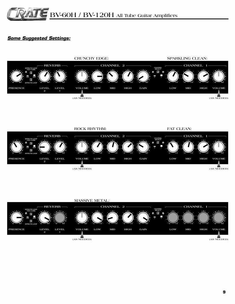
CRUNCHY EDGE: SPARKLING CLEAN:
ROCK RHYTHM: FAT CLEAN:
MASSIVE METAL:
Some Suggested Settings:
BV-60H / BV-120H All Tube Guitar Amplifiers
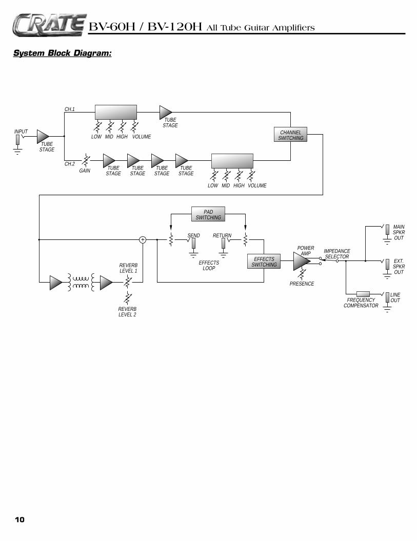
System Block Diagram:
INPUTMIDLOW HIGH VOLUME
REVERBLEVEL 1
REVERBLEVEL 2
PRESENCE
SEND RETURN
EFFECTSLOOP
TUBESTAGE
CH.1
CH.2
TUBESTAGE
TUBESTAGE
TUBESTAGE
TUBESTAGE
TUBESTAGE
CHANNELSWITCHING
PADSWITCHING
EFFECTSSWITCHING
FREQUENCYCOMPENSATOR
POWERAMP IMPEDANCE
SELECTOREXT.SPKROUT
MAINSPKROUT
LOW
GAIN
VOLUMEMID HIGH
LINEOUT
10
BV-60H / BV-120H All Tube Guitar Amplifiers

11
BV-60H / BV-120H All Tube Guitar Amplifiers
Declaration Of Conformity#35, Effective 01-01-2001
Manufacturer’s Name: SLM Electronics Production Facility: 1901 Congressional Drive, St. Louis, MO 63146, USAProduction Facility: 700 Hwy 202 W, Yellville, AR 72687, USAShipping Facility: 1400 Ferguson Ave., St. Louis, MO 63133, USAOffice Facility: 1400 Ferguson Ave., St. Louis, MO 63133, USA
Product Type: Audio Amplifier
Complies with the following Standards:Safety: EN60065, E60065, C22.2, UL6500 and/or UL813EMC: Directive 89/336/EEC, EN55103, EN55013, EN61000,
and/or FCC 47CFR 15B clASupplementary information provided by:
SLM Electronics - R & D Engineering 1901 Congressional Drive, St Louis, MO 63146, USA
Tel.: 314-569-0141, Fax: 314-569-0175
BV-60H / BV-120H All Tube Guitar Amplifiers
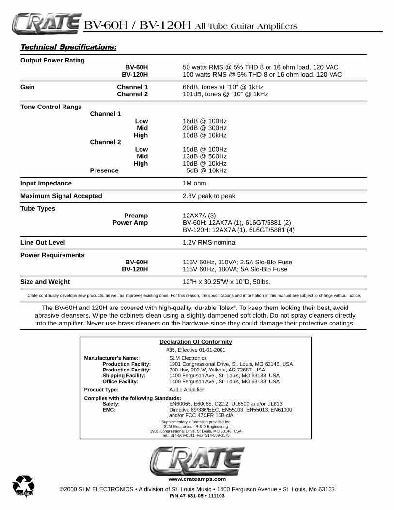
Technical Specifications:
Output Power RatingBV-60H 50 watts RMS @ 5% THD 8 or 16 ohm load, 120 VAC
BV-120H 100 watts RMS @ 5% THD 8 or 16 ohm load, 120 VAC
Gain Channel 1 66dB, tones at “10” @ 1kHzChannel 2 101dB, tones @ “10” @ 1kHz
Tone Control RangeChannel 1
Low 16dB @ 100HzMid 20dB @ 300Hz
High 10dB @ 10kHzChannel 2
Low 15dB @ 100HzMid 13dB @ 500Hz
High 10dB @ 10kHz Presence 5dB @ 10kHz
Input Impedance 1M ohm
Maximum Signal Accepted 2.8V peak to peak
Tube TypesPreamp 12AX7A (3)
Power Amp BV-60H: 12AX7A (1), 6L6GT/5881 (2)BV-120H: 12AX7A (1), 6L6GT/5881 (4)
Line Out Level 1.2V RMS nominal
Power RequirementsBV-60H 115V 60Hz, 110VA; 2.5A Slo-Blo Fuse
BV-120H 115V 60Hz, 180VA; 5A Slo-Blo Fuse
Size and Weight 12”H x 30.25”W x 10”D, 50lbs.
The BV-60H and 120H are covered with high-quality, durable Tolex®. To keep them looking their best, avoidabrasive cleansers. Wipe the cabinets clean using a slightly dampened soft cloth. Do not spray cleaners directlyinto the amplifier. Never use brass cleaners on the hardware since they could damage their protective coatings.
©2000 SLM ELECTRONICS • A division of St. Louis Music • 1400 Ferguson Avenue • St. Louis, Mo 63133P/N 47-631-05 • 111103
www.crateamps.com
Crate continually develops new products, as well as improves existing ones. For this reason, the specifications and information in this manual are subject to change without notice.