creating a wire harness with harness design -...
TRANSCRIPT

Creating a Wire Harness with HarnessDesign
Publication Numberspse01696


Creating a Wire Harness with HarnessDesign
Publication Numberspse01696

Proprietary and restricted rights notice
This software and related documentation are proprietary to Siemens ProductLifecycle Management Software Inc.
© 2010 Siemens Product Lifecycle Management Software Inc. All Rights Reserved.
All trademarks belong to their respective holders.
2 Creating a Wire Harness with Harness Design spse01696

Contents
Introduction . . . . . . . . . . . . . . . . . . . . . . . . . . . . . . . . . . . . . . . . . . . . . . 1-1
Introduction . . . . . . . . . . . . . . . . . . . . . . . . . . . . . . . . . . . . . . . . . . . . . . 0-1
Wire harness design workflow . . . . . . . . . . . . . . . . . . . . . . . . . . . . . . . . 2-1
Using BlueDots to Reposition Conductors and Components . . . . . . . . . . . . . . 2-3Using the Harness Wizard to create harness designs automatically . . . . . . . . . 2-4PathFinder in harness design . . . . . . . . . . . . . . . . . . . . . . . . . . . . . . . . . . . 2-12Removing conductors . . . . . . . . . . . . . . . . . . . . . . . . . . . . . . . . . . . . . . . . . 2-15Creating wire harness solid bodies . . . . . . . . . . . . . . . . . . . . . . . . . . . . . . . . 2-16Outputting wire harnesses to other formats . . . . . . . . . . . . . . . . . . . . . . . . . 2-17
Activity: Create a wire harness . . . . . . . . . . . . . . . . . . . . . . . . . . . . . . . . 3-1
Activity: Creating a wire harness with Harness Design . . . . . . . . . . . . . A-1
Open the Harness Design environment . . . . . . . . . . . . . . . . . . . . . . . . . . . . . A-2Activate the parts in the assembly . . . . . . . . . . . . . . . . . . . . . . . . . . . . . . . . A-3Hide the console part . . . . . . . . . . . . . . . . . . . . . . . . . . . . . . . . . . . . . . . . . A-4Start the Harness Wizard . . . . . . . . . . . . . . . . . . . . . . . . . . . . . . . . . . . . . . A-5Specify information for Harness Wizard Step - 1 of 3 . . . . . . . . . . . . . . . . . . . A-6Specify information for Harness Wizard Step - 2 of 3 . . . . . . . . . . . . . . . . . . . A-7Specify information for Harness Wizard Step - 3 of 3 . . . . . . . . . . . . . . . . . . . A-9Assign terminal A . . . . . . . . . . . . . . . . . . . . . . . . . . . . . . . . . . . . . . . . . . . A-10Assign terminal B . . . . . . . . . . . . . . . . . . . . . . . . . . . . . . . . . . . . . . . . . . . A-11Assign terminal C . . . . . . . . . . . . . . . . . . . . . . . . . . . . . . . . . . . . . . . . . . . A-12Fit the view . . . . . . . . . . . . . . . . . . . . . . . . . . . . . . . . . . . . . . . . . . . . . . . A-13View PathFinder . . . . . . . . . . . . . . . . . . . . . . . . . . . . . . . . . . . . . . . . . . . A-14Create a bundle . . . . . . . . . . . . . . . . . . . . . . . . . . . . . . . . . . . . . . . . . . . . A-15Re-select the Harness Wizard command . . . . . . . . . . . . . . . . . . . . . . . . . . . A-17Change the assembly display . . . . . . . . . . . . . . . . . . . . . . . . . . . . . . . . . . . A-18Zoom in on the assembly . . . . . . . . . . . . . . . . . . . . . . . . . . . . . . . . . . . . . . A-19Create a wire . . . . . . . . . . . . . . . . . . . . . . . . . . . . . . . . . . . . . . . . . . . . . . A-20Reposition OrientXpres . . . . . . . . . . . . . . . . . . . . . . . . . . . . . . . . . . . . . . . A-21Select the first point for the wire . . . . . . . . . . . . . . . . . . . . . . . . . . . . . . . . A-22Fit the view . . . . . . . . . . . . . . . . . . . . . . . . . . . . . . . . . . . . . . . . . . . . . . . A-23Zoom in on the upper gauge . . . . . . . . . . . . . . . . . . . . . . . . . . . . . . . . . . . . A-24Select the end point for the wire . . . . . . . . . . . . . . . . . . . . . . . . . . . . . . . . . A-25Finish the wire . . . . . . . . . . . . . . . . . . . . . . . . . . . . . . . . . . . . . . . . . . . . . A-26Fit the view . . . . . . . . . . . . . . . . . . . . . . . . . . . . . . . . . . . . . . . . . . . . . . . A-27Zoom in on the assembly . . . . . . . . . . . . . . . . . . . . . . . . . . . . . . . . . . . . . . A-28Create another wire . . . . . . . . . . . . . . . . . . . . . . . . . . . . . . . . . . . . . . . . . A-29Finish the wire . . . . . . . . . . . . . . . . . . . . . . . . . . . . . . . . . . . . . . . . . . . . . A-31Fit the view . . . . . . . . . . . . . . . . . . . . . . . . . . . . . . . . . . . . . . . . . . . . . . . A-32Create a cable . . . . . . . . . . . . . . . . . . . . . . . . . . . . . . . . . . . . . . . . . . . . . A-33Shade the view . . . . . . . . . . . . . . . . . . . . . . . . . . . . . . . . . . . . . . . . . . . . . A-35
spse01696 Creating a Wire Harness with Harness Design 3

Contents
Create a solid body of the wire harness . . . . . . . . . . . . . . . . . . . . . . . . . . . . A-36Change the view orientation . . . . . . . . . . . . . . . . . . . . . . . . . . . . . . . . . . . A-37Zoom in on the assembly . . . . . . . . . . . . . . . . . . . . . . . . . . . . . . . . . . . . . . A-38Move a wire . . . . . . . . . . . . . . . . . . . . . . . . . . . . . . . . . . . . . . . . . . . . . . . A-39Move two more wires . . . . . . . . . . . . . . . . . . . . . . . . . . . . . . . . . . . . . . . . A-41Fit the view . . . . . . . . . . . . . . . . . . . . . . . . . . . . . . . . . . . . . . . . . . . . . . . A-43Change the view orientation . . . . . . . . . . . . . . . . . . . . . . . . . . . . . . . . . . . A-44Display a hidden part . . . . . . . . . . . . . . . . . . . . . . . . . . . . . . . . . . . . . . . . A-45Hide the wires in the harness . . . . . . . . . . . . . . . . . . . . . . . . . . . . . . . . . . A-46Create a Wire Harness Report . . . . . . . . . . . . . . . . . . . . . . . . . . . . . . . . . . A-47Return to the Assembly environment . . . . . . . . . . . . . . . . . . . . . . . . . . . . . A-49Save the file . . . . . . . . . . . . . . . . . . . . . . . . . . . . . . . . . . . . . . . . . . . . . . . A-50
4 Creating a Wire Harness with Harness Design spse01696

Lesson
1 Introduction
Welcome to self paced training for Solid Edge. This course is designed to educate youin the use of Solid Edge. The course is self-paced and contains instruction followedby activities.
Solid Edge self-paced courses• spse01510—Sketching
• spse01515—Constructing base features
• spse01520—Moving and rotating faces
• spse01525—Working with face relationships
• spse01530—Constructing treatment features
• spse01535—Constructing procedural features
• spse01536—Modeling synchronous and ordered features
• spse01540—Modeling assemblies
• spse01541—Explode-Render-Animate
• spse01545—Creating detailed drawings
• spse01546—Sheet metal design
• spse01550—Practicing your skills with projects
• spse01560—Modeling a Part Using Surfaces
• spse01610—Solid Edge frame design
• spse01640—Assembly patterning
• spse01645—Assembly systems libraries
• spse01650—Working with large assemblies
• spse01655—Revising assemblies
• spse01660—Assembly reports
• spse01665—Replacing parts in an assembly
spse01696 Creating a Wire Harness with Harness Design 1-1
Lesson 1 Introduction
• spse01670—Designing in the context of an assembly
• spse01675—Assembly features
• spse01680—Inspecting assemblies
• spse01685—Alternate assemblies
• spse01690—Virtual components in assemblies
• spse01695—XpresRoute (tubing)
• spse01696—Creating a Wire Harness with Harness Design
• spse01424—Working with Solid Edge Embedded Client
Solid Edge self-paced modules
• spse01510—Sketching
• spse01515—Constructing base features
• spse01520—Moving and rotating faces
• spse01525—Working with geometric relationships
• spse01530—Constructing treatment features
• spse01535—Constructing procedural features
• spse01536—Modeling synchronous and ordered features
• spse01540—Modeling assemblies
• spse01545—Creating detailed drawings
• spse01546—Sheet metal design
• spse01550—Practicing your skills with projects
Start with the tutorials
Self-paced training begins where tutorials end. Tutorials are the quickest way foryou to become familiar with the basics of using Solid Edge. If you do not have anyexperience with Solid Edge, please start by working through the tutorials for basicpart modeling and editing before starting this self-paced training.
1-2 Creating a Wire Harness with Harness Design spse01696

Introduction
This course provides step-by-step instructions for using the commands in theHarness Design environment to create a harness design that contains several wires,a cable, and a bundle.
Harness Design allows you to easily construct wires, cables, and bundles fromone point to another in an assembly. The Harness Design module provides aHarness Wizard that allows you to automatically create a harness design based oninformation contained in an imported net list. The module also provides a structuredworkflow that allows you to quickly define a 3-D path between parts and define wire,cable, and bundle properties. After defining these properties, the software constructsthe wire, cable, or bundle.
This tutorial does not demonstrate everything Harness Design can do. Its purpose isto show you how powerful and intuitive Harness Design is, and to get you started sothat you can learn more on your own.
spse01696 Creating a Wire Harness with Harness Design 0-1


Lesson
2 Wire harness design workflow
Wire harness design overview
You can use the Wire Harness application to work with assemblies containingelectrical conductors.
To activate the Wire Harness application, choose Tools tab®Environsgroup®Harness.
Solid Edge Wire Harness Design is intended to work with round conductors only anddoes not support ribbon cables.
Note
There is no limit on the number of conductors you can use in an assembly.
Generally, there are two design processes used in harness design. In the first designprocess a 2D electrical schematic is developed first, and the 3D model is derived fromthe schematic. In the second design process there is no 2D schematic or it is notused in conjunction with the 3D model.
Harness design workflow
Based on the design process you use, there are two workflows for creating yourharness design:
• Automatic
• Manual
spse01696 Creating a Wire Harness with Harness Design 2-1

Lesson 2 Wire harness design workflow
Creating the harness design automatically workflow
1. Create a new list either manually or with an ECAD system.
2. Use the Harness Wizard command to import the net list file to Solid Edgeto assign component, connection, and terminal information for the harnessdesign.
3. Use the Move and Assemble commands to position the automatically placedcomponents if the assembly is not already created.
4. Bundle and route wires and cables as needed.
5. Add any wires or cables that were not included in the net list.
6. Verify all conductors exceed the minimum bend radius and they have theproper slack lengths.
7. Create manufacturing reports and create a 3D representation of the harness.
Creating the harness design manually workflow
1. Build the assembly to include all required components. You can place thecomponents in the Harness Design environment.
2. Create the wires and cables needed for your design.
3. Bundle and route wires and cables as needed.
4. Verify all conductors exceed the minimum bend radius and they have theproper slack lengths.
5. Create manufacturing reports and create a 3D representation of the harness.
2-2 Creating a Wire Harness with Harness Design spse01696

Wire harness design workflow
Using BlueDots to Reposition Conductors and ComponentsAfter creating a wire harness, you may need to reposition conductors and componentsto clean up the design. When you create a cable or bundle, a BlueDot is created atthe point where the wires, cables, and bundles meet.
You can drag the BlueDot to change the path the bundle or cable follows.
spse01696 Creating a Wire Harness with Harness Design 2-3

Lesson 2 Wire harness design workflow
Using the Harness Wizard to create harness designs automaticallyThe Harness Wizard command, located on the Tools tab®Harness group,automatically creates a wire harness. The wizard uses information stored in animported net list file to populate the components and conductors in an assembly.
Note
Before running the wizard, you should use the Assign Terminals commandin the Part environment to assign component and terminal names forcomponents that will be used in the harness design.
When you select the command, a series of dialogs takes you through the process ofdefining information about the wire harness.
To learn how to use the dialog box, see Using step 1 of the Harness Wizard.
To learn how to use the dialog box, see Using step 2 of the Harness Wizard.
To learn how to use the dialog box, see Using step 3 of the Harness Wizard.
2-4 Creating a Wire Harness with Harness Design spse01696

Wire harness design workflow
Using step 1 of the Harness Wizard
Use the Harness Wizard - Step 1 of 3 dialog box dialog box to specify:
• The format for the ECAD net list file.
• The component document used to create the harness.
• The conductor document used to create the harness.
Specify the format for the ECAD net list file
The Document Format option specifies the format for the net list file used tocreate the wire harness. Use the menu to display a list of document types foundin the SEHarness.txt file.
The SEHarness.txt file, located in the Solid Edge Program folder, defines thedata format for the ECAD net list files used to create the wire harness.
The SEHarness.txt file contains three sections:
• The company name, which also represents the format displayed in the menulist.
• The component definition used to define each column in the component file.
• The connection definition used to define each column in the connection file.
Specify the component document used to create the harness
The Component Document option specifies the component document used tocreate the wire harness. The document can be in .CMP or .CMP_XML format.
The component document contains information such as the component id,component name, and component description.
Specify the conductor document used to create the harness
The Connect Document option specifies the connection document used to createthe wire harness. The document can be in .CON or .CON_XML format.
The connection document contains information describing the connections inthe wire harness such as the component ID, color, and material, as well as thecomponent from ID and the component to ID.
spse01696 Creating a Wire Harness with Harness Design 2-5

Lesson 2 Wire harness design workflow
Using step 2 of the Harness Wizard
Use the Harness Wizard - Step 2 of 3 dialog box dialog box to specify:
• Assign components to a Component ID
• Assign occurrences of component part files already in the assembly
• Populate components into the assembly
Assign components
If you do not use the Assign Terminals command to make your componentand terminal assignments before running the wizard, your component filewill contain a component that has not been assigned. If your file contains anunassigned component, the component will be displayed in orange in the table.You do not have to exit the wizard to assign components.
To assign a component:
1. Click the component in the Components table.
2. Click the Assign Component command.
3. Click the part you want to assign the component to. The component ispopulated in the table and the Status and Occurrence Name columns areno longer highlighted.
You can right-click the Occurrences Name column for the component and clickBrowse on the shortcut menu to search for the part.
Note
A part can contain only one component.
Assign occurrences
When components are imported prior to running the wizard, Solid Edgeautomatically assigns an instance to all duplicate parts in the assembly basedon the order in which the parts are encountered. If the occurrences get out oforder, you can use the Assign Occurrence command to change the occurrencesfor a component.
To assign an occurrence when a component has already been assigned:
1. Click the highlighted row for the component containing the occurrence youwant to change.
2. Click the Assign Occurrence button.
3. Click the component you want to assign the occurrence to.
If the same part file is selected, the two part files swap instances. If the selectedpart is not associated with a component, the part is assigned to the highlightedcomponent.
2-6 Creating a Wire Harness with Harness Design spse01696

Wire harness design workflow
To assign an occurrence when a component has not been assigned:
1. Click the Assign Occurrence button.
2. Click the component you want to assign the occurrence to.
If the selected part is not associated with a component, the part is assigned tothe highlighted component. If the part is associated with a component, an errormessage is displayed.
Populate components
If a part listed in the components file is missing from the assembly, you canpopulate the component while in the harness wizard. All parts must bepopulated before you can proceed to the next step in the wizard. You can add theparts through the wizard or you can add them manually.
To populate a component:
1. Right-click in the Occurrence column for the highlighted component.
2. On the shortcut menu, click Browse to display the Open dialog box.
3. Select the appropriate part and click the Open button.
4. Click the Populate button.
Note
You do not have to click the Populate button after each browse. Youcan browse for all parts and then click the Populate button.
When populating components in an assembly, click the Populate Options buttonto display the Harness Populate Options dialog box, which allows you to defineinformation for an array of the components being brought into the assembly.
The array contains information about the components, but it does not knowwhere the parts associated with these components should be placed in theassembly. Since the part position is unknown, the parts are placed on the Top(XY) reference plane. Use the Assemble command to position the parts in theappropriate location after the wizard is complete.
spse01696 Creating a Wire Harness with Harness Design 2-7

Lesson 2 Wire harness design workflow
Using step 3 of the Harness Wizard
This dialog box displays information about the connections used to create the wireharness. You can use options on this dialog box to:
• Assign terminals on the component parts
• Delete wires from the harness
• Assign Attributes to a wire or cable
• Preview the harness
• Assign terminals
If your file contains undefined terminals, they highlight in orange. As withcomponents, you do not have to exit the wizard to assign a terminal.
To assign a terminal:
1. Click the terminal in the Connections table.
2. Click the Assign Terminal button.
3. In the graphic window, click the circular edge on the hightlighted part youwant to assign the terminal to. The terminal is assigned and the cells areno longer highlighted.
• Delete wires from the harness
If a wire listed in the connections document is not needed in the wire harness,you can delete it.
To delete a wire from the harness:
1. Right-click the wire you want to delete.
2. On the shortcut menu, click Delete Wire From Harness.
• Assign attributes to a wire or cable
You can assign attributes to a wire or cable while working in the wizard.
To assign an attribute to a wire:
1. Click the Solid Edge Attribute column for the wire.
2. Click the menu arrow.
The list includes attributes for the type of wire selected. For example, if thewire is 16 gage, the list will display only attributes for a 16 gage wire. Thereis also a Remove Filter entry in the list which allows you to remove the filterand display attributes for other types of wire.
3. Select an attribute from the list.
2-8 Creating a Wire Harness with Harness Design spse01696
Wire harness design workflow
To assign an attribute to a cable:
1. Click the Cable Attribute column for the cable.
2. Click the menu arrow.
The list includes attributes for the type of cable selected. There is also aRemove Filter entry in the list which allows you to remove the filter anddisplay attributes for other types of cable.
3. Select an attribute from the list.
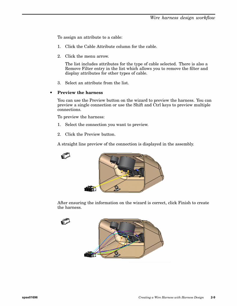
• Preview the harness
You can use the Preview button on the wizard to preview the harness. You canpreview a single connection or use the Shift and Ctrl keys to preview multipleconnections.
To preview the harness:
1. Select the connection you want to preview.
2. Click the Preview button.
A straight line preview of the connection is displayed in the assembly.
After ensuring the information on the wizard is correct, click Finish to createthe harness.
spse01696 Creating a Wire Harness with Harness Design 2-9

Lesson 2 Wire harness design workflow
Once the harness is complete, you can use the Cable or Bundle command togroup the wires or cables in the design.
After creating a wire harness, you may need to reposition conductors andcomponents to clean up the design. When you create a cable or bundle, a bluedotis created at the point where the wires, cables, and bundles meet.
You can drag the bluedot to change the path the bundle or cable follows.
You can also clean up the harness design by using the Move command to drag acomponent to a new location.
2-10 Creating a Wire Harness with Harness Design spse01696

Wire harness design workflow
Once you move the component to a new location, the link to the conductors isautomatically updated.
spse01696 Creating a Wire Harness with Harness Design 2-11

Lesson 2 Wire harness design workflow
PathFinder in harness designAs you create paths and conductors, they are added to PathFinder.
2-12 Creating a Wire Harness with Harness Design spse01696

Wire harness design workflow
If you move the cursor over a conductor in PathFinder, all occurrences of theconductor are outlined with a red box,
and they are highlighted in the graphics window.
spse01696 Creating a Wire Harness with Harness Design 2-13

Lesson 2 Wire harness design workflow
Notice that the wire you highlighted is displayed in a solid color until the point itbecomes part of a cable. At that point, the display becomes a dashed line. Also noticethat the color of the dashed line changes at the point the cable and wires becomepart of a bundle.
If you position the cursor over a cable in PathFinder, all occurrences of the cableare outlined and the cable highlights in a solid color and the bundle containingthe cable highlights as a dashed line. Notice that the wires included in the cabledo not highlight.
If you position the cursor over a bundle in PathFinder, all occurrences of the bundleare outlined and the bundle highlights in a solid color. Notice that the wires andcables included in the bundle do not highlight.
You can right-click on a conductor in PathFinder to display a list of shortcutcommands that allow you to manipulate the conductors.
2-14 Creating a Wire Harness with Harness Design spse01696

Wire harness design workflow
Removing conductorsYou can use the Remove command to remove a conductor from its parent. To accessthe command, right-click the mouse button on a conductor and on the shortcutmenu, click Remove.
When you remove a conductor from a higher level object, it is removed from thedefinition of all higher level objects. The existing to and from points of the conductorare maintained. The path segment(s) shared between the selected conductor and itshigher level is removed from the conductor’s definition. A new segment is generatedto replace the segment that was removed.
spse01696 Creating a Wire Harness with Harness Design 2-15

Lesson 2 Wire harness design workflow
Creating wire harness solid bodiesYou can use the Create Physical Conductor command to create a solid body of thewires, cables, and bundles that make up the harness design. This is useful when youneed a rendering or detailed drawing of your harness design,
To access the command, right-click on a conductor in PathFinder. The solid body thatis created is only for the selected conductor. In other words, if you select a cable, thecommand does not create solid bodies for the wires contained in the cable. You canright-click on the Harness node in Assembly PathFinder to create all of the solidsat once. The solid bodies are embedded in the assembly and no new documents areadded to the assembly.
Note
Any paths found in the harness design that do not contain attributes will notbe included in the creation of the solid body.
When you create a solid body for a conductor, the symbol adjacent to the conductorin PathFinder is updated to indicate that a solid body has been created for theconductor.
Note
To select multiple conductors, you can hold down the Ctrl key, and thenclick the conductors you want. To select a list of conductors, click on thefirst conductor in the list, hold down the Shift key, and then click the lastconductor in the list.
After you create a solid body for a conductor, additional shortcut menu commandsare available to manipulate the solid bodies.
You can use the Show Physical Conductor and Hide Physical Conductor commandsto control the display of the solid bodies. The solid body is automatically shown oncreation, so you can use the Hide Physical Conductor command to conceal the newlycreated body. Changes made to the display of the physical body do no affect thedisplay state of the conductor used to create the body.
You can use the Delete Physical Conductor command to delete the solid body withoutdeleting the conductor.
2-16 Creating a Wire Harness with Harness Design spse01696

Wire harness design workflow
Outputting wire harnesses to other formatsYou can use the Save As ECAD command to save your wire harness component andconnection information so that it can be used by other ECAD software systems. Youcan export the information to ECAD system-specific format or to .XML format.
Note
The command will only export information for conductors that have beenattributed. Any paths that do not contain attributes will not be included inthe file.
When you select the command, the Save As ECAD dialog box is displayed. You canuse this dialog box to specify the format to which you want to save the information.You can also specify the name, location, and format of the components andconnections files.
The components file contains information about the components in the wire harnesssuch as the unique id, component name, and component description. You can savethe components file to .CMP or .CMP_XML format.
The connection file contains information about the connections in the wire harnesssuch as the wire id, fromcomponentid, and the tocomponentid. You can save thecomponents file to .CON or .CON_XML format.
spse01696 Creating a Wire Harness with Harness Design 2-17


Lesson
3 Activity: Create a wire harness
This activity guides you through the creation of a harness design that containsseveral wires, a cable, and a bundle.
Turn to Appendix A for the activity.
spse01696 Creating a Wire Harness with Harness Design 3-1


A Activity: Creating a wire harnesswith Harness Design
Open activity file
▸ In the Solid Edge Training folder, open seaabwh.asm. In the Open File dialogbox set the Activate All activation override so that the assembly opens with allparts active.
spse01696 Creating a Wire Harness with Harness Design A-1

A Activity: Creating a wire harness with Harness Design
Open the Harness Design environment
▸ Click Tools tab®Environs group®Harness Design.
The system displays the Wire Harness toolbar so you can create wire harnessconductors (wires, cables, or bundles).
You will use PathFinder for most of this activity.
A-2 Creating a Wire Harness with Harness Design spse01696

Activity: Creating a wire harness with Harness Design
Activate the parts in the assembly
This activity requires that the parts in the assembly are active. Several factorsdetermine whether or not all parts within the assembly are active on your computer.
▸ To ensure that the parts are active, in PathFinder, right-click in theseaabwh.asm entry, and click Activate on the shortcut menu.
spse01696 Creating a Wire Harness with Harness Design A-3

A Activity: Creating a wire harness with Harness Design
Hide the console part
▸ In the PathFinder tab, position the cursor over the Console1.par entry, thenclick the right mouse button to display the shortcut menu.
▸ On the shortcut menu, click Hide to hide the part.
A-4 Creating a Wire Harness with Harness Design spse01696

Activity: Creating a wire harness with Harness Design
Start the Harness Wizard
The Harness Wizard consists of three dialog boxes that allow you to automaticallycreate a harness design based on information contained in an imported net list file.
▸ On the Wire Harness toolbar, click the Harness Wizard button.
spse01696 Creating a Wire Harness with Harness Design A-5

A Activity: Creating a wire harness with Harness Design
Specify information for Harness Wizard Step - 1 of 3
The Harness Wizard - Step 1 of 3 dialog box allows you to specify:
• The format for the eCAD net list file.
• The component document used to create the harness.
• The conductor document used to create the harness.
▸ In the Document Format field, click the menu arrow and select Sample fromthe list.
▸ In the Component Document field, use the Browse button to select $:\programFiles\Solid Edge ST3\Training\Wiring Harness\Seeabwh1.cmp.
▸ In the Connection Document field, use the Browse button to select$:\program Files\Solid Edge ST3\Training\Wiring Harness\Seeabwh1.con.
▸ Click the Next button.
A-6 Creating a Wire Harness with Harness Design spse01696

Activity: Creating a wire harness with Harness Design
Specify information for Harness Wizard Step - 2 of 3
The Harness Wizard - Step 2 of 3 dialog box displays information about thecomponents used to create the wire harness. The dialog box contains commandsand options that allow you to:
• Assign components
• Assign occurrences
• Populate components
Notice that the status for component Volume1 is Not Populated. This indicatesthat the component has not been assigned to a part. Normally, you would use theAssign Terminals command to assign components and terminals before runningthe wizard. However, if this has not been done, you can make these assignmentswithin the wizard.
▸ Click the row containing Volume1 and click the Assign Component button
.
▸ In the graphic window, click Potentiometer2.par, as shown in the illustration.
spse01696 Creating a Wire Harness with Harness Design A-7

A Activity: Creating a wire harness with Harness Design
Notice that the dialog updates to indicate the status of volume1 is now populated.
▸ Click the Next button.
A-8 Creating a Wire Harness with Harness Design spse01696

Activity: Creating a wire harness with Harness Design
Specify information for Harness Wizard Step - 3 of 3
The Harness Wizard - Step 3 of 3 dialog box displays information about theconductors used to create the wire harness. The dialog box contains commandsthat allow you to:
• Assign terminals
• Delete wires from the harness
• Assign attributes to a wire or cable
• Preview the harness
Notice that there are three From Terminals highlighted in orange and the statusfor these terminals is Not Defined. These represent terminals on the volume1component that need to be defined.
spse01696 Creating a Wire Harness with Harness Design A-9

A Activity: Creating a wire harness with Harness Design
Assign terminal A
▸ Click From Terminal "a" and click the Assign Terminal button .
▸ On the status bar at the bottom of the window, click the Zoom Area button
.
▸ Click above and to the left of Potetionmeter2.par, and then again belowand to the right as shown in the illustration. This defines a rectangle thatbecomes the view area.
▸ Click the right mouse button to end the Zoom Area command.
▸ Click the circular edge to assign terminal a.
A-10 Creating a Wire Harness with Harness Design spse01696

Activity: Creating a wire harness with Harness Design
Assign terminal B
▸ Click From Terminal "b" and click the Assign Terminal button .
▸ Click the circular edge to assign the terminal.
spse01696 Creating a Wire Harness with Harness Design A-11

A Activity: Creating a wire harness with Harness Design
Assign terminal C
▸ Click From Terminal "c" and click the Assign Terminal button .
▸ Click the circular edge to assign the terminal.
▸ Click the Finish button to complete the wizard.
A-12 Creating a Wire Harness with Harness Design spse01696

Activity: Creating a wire harness with Harness Design
Fit the view
▸ Click the View tab®Orient Group®Fit button to fit the assembly in thewindow.
spse01696 Creating a Wire Harness with Harness Design A-13

A Activity: Creating a wire harness with Harness Design
View PathFinder
▸ In PathFinder, click "+" symbol adjacent to the Wires entry.
Notice entries have been added for every wire created with the Harness Wizard.
A-14 Creating a Wire Harness with Harness Design spse01696

Activity: Creating a wire harness with Harness Design
Create a bundle
The Bundle command creates a harness bundle from a set of wires and cables. Theresult is a single path that can be created across several components within theharness assembly. When defining the path, you can define points to create the pathor you can select an existing path created with the Path command. For this bundle, apath has already been created.
▸ In PathFinder, click the arrow next to the Paths entry.
▸ Click the right mouse button on Path_1 and click Show on the shortcut menu.
▸ Click the Home tab®Harness group®Bundle button .
▸ Hold the left mouse button down, then drag a box around plug14.par, asshown in the illustration, to select the wires to include in the bundle.
▸ Click the Accept button.
▸ Make sure the Use Existing Path button on the ribbon bar is selected.
spse01696 Creating a Wire Harness with Harness Design A-15

A Activity: Creating a wire harness with Harness Design
▸ Click the existing path shown in the illustration.
▸ Click the Accept button.
▸ Click Preview and then click Finish.
A-16 Creating a Wire Harness with Harness Design spse01696

Activity: Creating a wire harness with Harness Design
Re-select the Harness Wizard command
You need to use the Harness Wizard to place another set of wires in the assembly.
▸ Click the Home tab®Wizard group®Harness Wizard button .
▸ On the Harness Wizard - Step 1 of 3 dialog box:
▸ In the Document Format field, click the menu arrow and select Sample fromthe list.
▸ In the Component Document field, use the Browse button to select $:\programFiles\Solid Edge ST3\Training\Wiring Harness\Seeabwh2.cmp.
▸ In the Connection Document field, use the Browse button to select$:\program Files\Solid Edge ST3\Training\Wiring Harness\Seeabwh2.con.
▸ Click the Next button.
▸ On the Harness Wizard - Step 2 of 3 dialog box, click the Next button.
▸ On the Harness Wizard - Step 3 of 3 dialog box, click the Finish button.
spse01696 Creating a Wire Harness with Harness Design A-17

A Activity: Creating a wire harness with Harness Design
Change the assembly display
▸ On the status bar at the bottom of the window, click the Visible and Hidden
Edges button .
A-18 Creating a Wire Harness with Harness Design spse01696

Activity: Creating a wire harness with Harness Design
Zoom in on the assembly
▸ On the status bar at the bottom of the window, click the Zoom Area button
.
▸ Click above and to the left of plug4.par, and then again below and to theright of the fan as shown in the illustration. This defines a rectangle thatbecomes the view area.
▸ Click the right mouse button to end the Zoom Area command.
spse01696 Creating a Wire Harness with Harness Design A-19

A Activity: Creating a wire harness with Harness Design
Create a wire
▸ Click the Home tab®Harness group®Wire button .
A-20 Creating a Wire Harness with Harness Design spse01696
Activity: Creating a wire harness with Harness Design
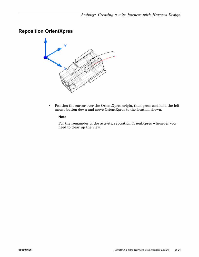
Reposition OrientXpres
▸ Position the cursor over the OrientXpres origin, then press and hold the leftmouse button down and move OrientXpres to the location shown.
Note
For the remainder of the activity, reposition OrientXpres whenever youneed to clear up the view.
spse01696 Creating a Wire Harness with Harness Design A-21

A Activity: Creating a wire harness with Harness Design
Select the first point for the wire
▸ Make sure the Create Path button is selected .
▸ Click the Keypoint Locate button .
▸ Click the Keypoints button .
▸ Select the Center Point button from the list .
▸ Highlight the center point displayed in the illustration, and when ithighlights, click to select it.
A-22 Creating a Wire Harness with Harness Design spse01696

Activity: Creating a wire harness with Harness Design
Fit the view
▸ Click the View tab®Orient Group®Fit button to fit the assembly in thewindow.
spse01696 Creating a Wire Harness with Harness Design A-23

A Activity: Creating a wire harness with Harness Design
Zoom in on the upper gauge
▸ On the status bar at the bottom of the window, click the Zoom Area button
.
▸ Click above and to the left of the upper gauge, and then again below and tothe right of the fan as shown in the illustration. This defines a rectanglethat becomes the view area.
▸ Click the right mouse button to end the Zoom Area command.
A-24 Creating a Wire Harness with Harness Design spse01696

Activity: Creating a wire harness with Harness Design
Select the end point for the wire
▸ Highlight the center point displayed in the illustration, and when ithighlights, click to select it.
▸ Position the cursor above and beyond terminal as shown in the illustration,and right-click to accept the end point.
▸ Set the Material as shown in the illustration.
▸ Click the Preview button.
spse01696 Creating a Wire Harness with Harness Design A-25

A Activity: Creating a wire harness with Harness Design
Finish the wire
▸ Click the Finish button to complete the wire.
A-26 Creating a Wire Harness with Harness Design spse01696

Activity: Creating a wire harness with Harness Design
Fit the view
▸ Click the View tab®Orient Group®Fit button to fit the assembly in thewindow.
spse01696 Creating a Wire Harness with Harness Design A-27

A Activity: Creating a wire harness with Harness Design
Zoom in on the assembly
▸ On the status bar at the bottom of the window, click the Zoom Area button
.
▸ Click above and to the left of plug4.par, and then again below and to theright of the fan as shown in the illustration. This defines a rectangle thatbecomes the view area.
▸ Click the right mouse button to end the Zoom Area command.
A-28 Creating a Wire Harness with Harness Design spse01696

Activity: Creating a wire harness with Harness Design
Create another wire
▸ Click the Home tab®Harness group®Wire button .
Use the same option setting you used to create the first wire.
▸ Select the circular edge shown in the illustration to define the first pointfor the wire.
▸ Select the circular edge shown in the illustration to define the end pointfor the wire.
spse01696 Creating a Wire Harness with Harness Design A-29

A Activity: Creating a wire harness with Harness Design
▸ Position the wire as shown in the illustration and click the Accept button.
▸ Set the Material as shown in the illustration.
▸ Click the Preview button.
A-30 Creating a Wire Harness with Harness Design spse01696

Activity: Creating a wire harness with Harness Design
Finish the wire
▸ Click the Finish button to complete the wire.
spse01696 Creating a Wire Harness with Harness Design A-31

A Activity: Creating a wire harness with Harness Design
Fit the view
▸ Click the View tab®Orient Group®Fit button to fit the assembly in thewindow.
A-32 Creating a Wire Harness with Harness Design spse01696

Activity: Creating a wire harness with Harness Design
Create a cable
▸ Click the Home tab®Harness group®Cable button .
▸ Hold the left mouse button down, then drag a box around plug4.par, asshown in the illustration, to select the wires to include in the cable.
▸ Click the Accept button.
▸ Make sure the Create Path button is selected .
▸ Create the path as shown in the illustration.
spse01696 Creating a Wire Harness with Harness Design A-33

A Activity: Creating a wire harness with Harness Design
▸ Set the Material to 22/15-gage Stranded Copper Gray as shown in theillustration.
▸ Click Preview and then click Finish.
A-34 Creating a Wire Harness with Harness Design spse01696

Activity: Creating a wire harness with Harness Design
Shade the view
▸ On the status bar at the bottom of the window, click the Shade with Visible
Edges button .
spse01696 Creating a Wire Harness with Harness Design A-35
A Activity: Creating a wire harness with Harness Design
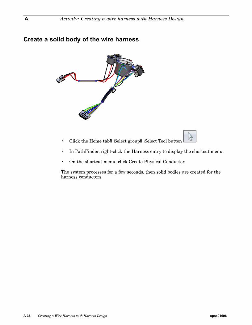
Create a solid body of the wire harness
▸ Click the Home tab®Select group®Select Tool button .
▸ In PathFinder, right-click the Harness entry to display the shortcut menu.
▸ On the shortcut menu, click Create Physical Conductor.
The system processes for a few seconds, then solid bodies are created for theharness conductors.
A-36 Creating a Wire Harness with Harness Design spse01696

Activity: Creating a wire harness with Harness Design
Change the view orientation
▸ Press the Ctrl + R keys to align the view with the Right view.
spse01696 Creating a Wire Harness with Harness Design A-37

A Activity: Creating a wire harness with Harness Design
Zoom in on the assembly
▸ On the status bar at the bottom of the window, click the Zoom Area button
.
▸ Click above and to the left of rocker1.par, and then again below and to theright of rocker1.par as shown in the illustration.
▸ Click the right mouse button anywhere in the graphic window to end theZoom Area command.
A-38 Creating a Wire Harness with Harness Design spse01696

Activity: Creating a wire harness with Harness Design
Move a wire
▸ Position the cursor over the path shown highlighted in the illustrationabove, stop moving the mouse for a moment, and notice that the cursorimage changes to indicate that multiple selections are available. Also noticethat the cursor image indicates which button you must click to display the
QuickPick list. In this case, the right mouse button .
▸ Click the right mouse button, and the QuickPick list is displayed. Movethe cursor over the different entries in QuickPick, and notice that differentelements of the model highlight. QuickPick allows you to select exactlythe element you want, the first time, without having to reject unwantedelements.
▸ Use QuickPick to highlight the path used to define Wire 9 and then click theright mouse button.. In this example, it is Path_25, but your path may havea different name. If multiple paths are displayed in QuickPick, select thepath closest to the occurrence in Rocker1.par.
▸ On the shortcut menu, click Edit Definition.
spse01696 Creating a Wire Harness with Harness Design A-39

A Activity: Creating a wire harness with Harness Design
▸ Click the point shown in the illustration.
▸ Drag the point to the approximate location shown in the illustration, andthen right-click to place the wire.
A-40 Creating a Wire Harness with Harness Design spse01696

Activity: Creating a wire harness with Harness Design
Move two more wires
▸ Use the method described in the previous step to move the path used todefine wire 7.
spse01696 Creating a Wire Harness with Harness Design A-41

A Activity: Creating a wire harness with Harness Design
▸ and the path used to define wire 8.
After you have moved these wires, the wire harness should look similar to theillustration above.
A-42 Creating a Wire Harness with Harness Design spse01696

Activity: Creating a wire harness with Harness Design
Fit the view
▸ Click the View tab®Orient Group®Fit button to fit the assembly in thewindow.
spse01696 Creating a Wire Harness with Harness Design A-43

A Activity: Creating a wire harness with Harness Design
Change the view orientation
▸ Press the Ctrl + I keys to align the view with the Isometric view.
A-44 Creating a Wire Harness with Harness Design spse01696

Activity: Creating a wire harness with Harness Design
Display a hidden part
▸ In the PathFinder tab, position the cursor over the Console1.par entry, thenright-click the mouse button to display the shortcut menu.
▸ On the shortcut menu, click Show to display the hidden part.
spse01696 Creating a Wire Harness with Harness Design A-45

A Activity: Creating a wire harness with Harness Design
Hide the wires in the harness
▸ In the PathFinder tab, position the cursor over the Wires entry, then clickthe right mouse button to display the shortcut menu.
▸ On the shortcut menu, click Hide to hide the wires.
A-46 Creating a Wire Harness with Harness Design spse01696

Activity: Creating a wire harness with Harness Design
Create a Wire Harness Report
You can create a report that lists the components and connections contained inan assembly.
▸ Click Tools tab®Assistants group®Harness Reports.
▸ On the Harness Report dialog box:
▸ Set the Connections option.
▸ Set the All Harness Connections in the Assembly.
▸ Click OK to generate the report.
spse01696 Creating a Wire Harness with Harness Design A-47

A Activity: Creating a wire harness with Harness Design
A Reports dialog box displays a list of cables expanded into an indented listof the wire paths.
You can generate a report based on all components or connections in theassembly, the components or connections that are currently shown in theassembly, or the components or connections that are currently selected in theassembly. You can save reports, print reports, and copy reports to the clipboard.
▸ Click the Close button to dismiss the report.
A-48 Creating a Wire Harness with Harness Design spse01696

Activity: Creating a wire harness with Harness Design
Return to the Assembly environment
▸ Click the Tools tab®Close group®Close Harness button .
spse01696 Creating a Wire Harness with Harness Design A-49

A Activity: Creating a wire harness with Harness Design
Save the file
▸ On the Quick Access toolbar, click the Save button to save the document .
Congratulations!
• Try modifying the wires using the Properties dialog box.
• This completes the activity.
A-50 Creating a Wire Harness with Harness Design spse01696