creating highly available web sitesdownload.microsoft.com/download/win2000srv/spwp/101/nt5... ·...
TRANSCRIPT

Operating System
Creating a Highly Available Web Site:A Step-by-Step Guide to Setting Up a Site Using Windows NT Server 4.0, Enterprise Edition, Windows 2000 Advanced Server, or Windows 2000 Datacenter Server
Abstract
This paper introduces the architecture needed to create a highly available Web site using Windows NT® Server, Enterprise Edition technologies, or the Windows® 2000 Advanced Server, or Windows 2000 Datacenter Server infrastructure. High availability refers to the ability of a multi-server Web services hosting site to withstand hardware or software outages that occur on the site’s individual servers.
This paper provides step-by-step instructions that demonstrate how to build the servers and the supporting infrastructure for an example site based on both architectures. The architectures described are designed to both protect the data of a multi-server Web site during planned or unplanned outages and to keep the sites up and running.

© 1999 Microsoft Corporation. All rights reserved.The information contained in this document represents the current view of Microsoft Corporation on the issues discussed as of the date of publication. Because Microsoft must respond to changing market conditions, it should not be interpreted to be a commitment on the part of Microsoft, and Microsoft cannot guarantee the accuracy of any information presented after the date of publication.Note that this paper documents Windows 2000 Server Beta 3 functionality.This white paper is for informational purposes only. MICROSOFT MAKES NO WARRANTIES, EXPRESS OR IMPLIED, IN THIS DOCUMENT.Microsoft, Active Directory, FrontPage, Windows, and Windows NT are either trademarks or registered trademarks of Microsoft Corporation.Other product or company names mentioned herein may be the trademarks of their respective owners.Microsoft Corporation • One Microsoft Way • Redmond, WA 98052-6399 • USA10/99

INTRODUCTION.................................................................................1Document Organization 2
BUILDING A HIGHLY AVAILABLE WEB SITE........................................3Hardware 3
Data Storage 3Networking 3
Highly Available Example Site Architecture 4Front-end and Back-end Tiers 5Location of Web Content Storage 5Security Issues 6The Front End 7The Back End 9
BUILDING THE WINDOWS NT 4.0-BASED EXAMPLE HIGH AVAILABILITY SITE.................................................................................................11Required Software 11Installation Overview 11Setting Up the Domain Controller 11
Installing Windows NT Server 12Configuring DNS on the Staging Server 12
Setting Up the Back-end Servers 13Installing Windows NT Server 14Installing RAID support 15Installing Cluster Server on COMCLUSTER1 16Installing Cluster Server on COMCLUSTER2 17Verifying the Cluster Installation 17Installing MSDTC 18Installing Windows NT 4.0 Service Pack 4 18Installing SQL Server 19Creating the SQL Server Cluster 20Creating a File Share in the Cluster 21Configuring Microsoft Cluster Server 21
Setting Up the Front End 22Software to be Installed 22Installing Windows NT 23Installing Windows NT Load Balancing Service 24Installing Site Server Commerce Edition 28Mapping Front-end Web Site to Back-end Cluster Service File Share 29
Analyzing Site Traffic Using Site Server 30
BUILDING THE WINDOWS 2000-BASED HIGHLY AVAILABLE WEB SITE.......................................................................................................32Hardware 32
Data Storage 32

Networking 32Front-End and Back-End Tiers 33
Installation Overview 33Setting Up the Domain Controller 33
Installing Windows 2000 Advanced Server for the Domain Controller 33Configuring DNS on the Stage1 Server 35
Setting Up the Back End Servers 36Installing Windows 2000 Advanced Server for the Back-End Servers 36Installing RAID Support 37Installing Cluster Services on COMCLUSTER1 38Installing Cluster Server on COMCLUSTER2 39Verifying the Cluster Installation 39Installing SQL Server 39Creating the SQL Server Cluster 40Configuring Microsoft Cluster Service 41Creating a File Share in the Cluster 41
Setting Up the Front End 42Installing Windows 2000 Advanced Server 42Installing Windows 2000 Network Load Balancing 44
For more information......................................................................47

As Web-based applications continue to gain in importance, it becomes increasingly necessary to host these applications on a flexible platform that provides scalability, reliability, and availability. Clustering technologies can satisfy these needs today, providing a solid infrastructure on which to deploy demanding Web applications with confidence, satisfying the most exacting customer demands.
Microsoft® provides different types of clustering technologies for specific situations. In the Windows® 2000 Advanced Server operating system, a server cluster running the Cluster service provides failover capability for software services, and Network Load Balancing (NLB) provides the means to distribute workloads for TCP/IP protocol services such as HTTP and Lightweight Directory Access Protocol (LDAP) across multiple servers to increase throughput and availability. (In the Windows NT® Server, Enterprise Edition architecture, the clustering capability is referred to as the Microsoft Cluster Server or MSCS, and the load-balancing feature is called Windows NT Load Balancing Service or WLBS. For the sake of consistency, this document will use the Windows 2000 feature names.)
Both of these technologies are included as part of Microsoft Windows 2000 Advanced Server and Windows 2000 Datacenter Server, and Windows NT Server, Enterprise Edition. While either of the clustering technologies could be used separately to achieve a high level of service for a Web site, the scalability, reliability, and availability of the Web site is maximized when both technologies are used in conjunction with one another to build the site's infrastructure.
In this paper, the term high availability refers to the ability of a multi-server Web services hosting site to withstand hardware or software outages that occur on the site’s individual servers. These outages can be either planned or unplanned. An example of a planned outage is taking a server down for maintenance to perform a software update. In this example, while the server is down for the software maintenance operation, the rest of the site stays online providing service to users. An example of an unplanned outage is a catastrophic server failure. In this case, the rest of the site stays online providing service to users because the processes that were providing data services for the site failed over to the remaining server clusters during the server failure. The architecture described in this paper is designed to both protect the data of such a Web site and to keep the site up and running.
This document walks you through the steps for building a sample architecture for a highly available and scalable Web site, whether you are working in a Windows 2000 Advanced or Datacenter Server or Windows NT Server, Enterprise Edition-based network The Web sites described in this document can be used to deliver highly available Web hosting, for either dedicated or shared sites. A similar site design can also be used to host a highly available intranet site.
This document is not intended to describe the features and functions of Windows Clustering and Network Load Balancing. It is assumed that you have basic knowledge of the Microsoft technologies used in the high availability scenario. For more information about these technologies, see the For More Information section of
Creating Highly Available Web Sites White Paper 1
INTRODUCTION

this document.
Document OrganizationThis document cover four main topics:
Building a Highly Available Web Site—This section gives an overview of the multi-tiered architecture necessary for maintaining a highly available Web site. Both Windows 2000 Advanced Server and Windows NT Server, Enterprise Edition provide system services for clustering, the technology that supports the architecture for creating a highly available Web site. Because there are also important differences in how the two implement server clusters, the step-by-step directions showing how to build the servers and supporting infrastructure for the sample site are divided into two sections: one describes the procedures for building a sample site using the Windows NT Server, Enterprise Edition operating system, and the other uses the Windows 2000 Advanced Server operating system to build the site.
Availability and Scalability for Microsoft SQL Server 7.0 Database-Driven Web Sites—Using the highly available infrastructure, a cluster-hosted Microsoft SQL Server™ 7.0 database is added to the example to enable database-driven Web sites.
Sample Configuration for Microsoft Commerce Server—Microsoft Site Server 3.0, Commerce Edition (Commerce Server) is installed on the example site that is Windows NT-based to take advantage of the availability and scalability of this infrastructure. The Volcano Coffee sample site is used in the Commerce Server example.
Measuring Usage on a Highly Available Web Site—This section describes how to use the Site Server Usage Analysis log for multiple-node Web sites to derive site usage information for the NT-based network.
This section introduces the architecture for a highly available Web site.
HardwareThe example site uses a total of six servers, all running either Windows NT Server, Enterprise Edition, or Windows 2000 Advanced Server.
The hardware used in the example site may be considered as a baseline for a highly available system. Check with your hardware vendor for more information about hardware solutions for increased availability, such as dual interface Ethernet adapters and uninterruptible power supplies.
When building a highly available site, it is recommended that you use hardware listed in the Windows Hardware Compatibility List (HCL).
Creating Highly Available Web Sites White Paper 2
BUILDING A HIGHLY AVAILABLE WEB SITE

Data Storage
Data storage for the Web site (the back end) is managed by two servers running the Cluster service (called MSCS in Windows NT Server 4.0) with a Fibre Channel connection to a shared RAID level 5 disk array. The server cluster provides availability in the event of a server failure, and the RAID array provides availability in the event of a disk failure.
The disk technology provided in modern servers and arrays can detect potential disk failures before the failure happens. If a disk failure is predicted by the system, the failing disk can be hot swapped out of the RAID 5 array and replaced with no loss of service for the site. RAID 5 arrays can be implemented in software using built-in Windows NT Server, Enterprise Edition or Windows 2000 Advanced Server services. However, the example sites use a hardware implementation for increased data access performance.
Note: The type of file system used in this configuration is critical. All the disks used in this architecture must be formatted to use the NTFS file format because it provides a much higher level of security and data integrity as compared to the FAT file format.
Networking
Each server has two 100-Mbps Ethernet network interface cards (NICs). The TCP/IP protocol is used throughout the example site.
In the back-end servers running the Cluster service, one NIC is connected to a private network (10.0.0.x) providing access to the Web servers through a 100-Mbps switch. The other NIC provides the cluster heartbeat mechanism and is connected to the other cluster server by way of an Ethernet crossover cable. This example uses a private network address for the cluster heartbeat network that uses the 11.0.0.x range of IP addresses.
In the front-end servers providing Web services, one NIC is connected to a 100-Mbps switch that is connected to a network that routes to the Internet. This NIC is bound with a public IP address of 192.168.18.155. The other NIC is connected to the private network (10.0.0.x) through the 100-Mbps switch that interconnects the servers in the site.
Highly Available Example Site ArchitectureService providers have different preexisting infrastructure and business models. The architecture of the example site is intended to be sufficiently generic that the core concepts can be deployed in a variety of scenarios.
The following diagram, Figure 1, shows the architecture of the example site for the Windows NT Server, Enterprise Edition-based network. The IP addresses and connections for different parts of the network are shown in different colors, as follows:
The external network is shown in blue.
Creating Highly Available Web Sites White Paper 3

The internal network is shown in green.
The cluster heartbeat network is shown in purple.
INTERNET
Internet User
Internet User
ComCluster1NT Server Enterprise
10.0.0.411.0.0.1SQL 7.0
ComCluster2NT Server Enterprise
10.0.0.511.0.0.2SQL 7.0
FrontEnd1NT Server Enterprise Edition
WLBS Site Server192.168.18.158
10.0.0.1-IIS4, -SP4
FrontEnd2NT Server Enterprise Edition
WLBS Site Server192.168.18.159
10.0.0.2-IIS4, -SP4
FrontEnd3NT Server Enterprise Edition
WLBS Site Server192.168.18.158
10.0.0.3-IIS4, -SP4
Laptop
Firewall
RouterSwitch
cluster.domain.com192.168.18.155
Switch Hub Disk arrayFiber Interconnect
RAID5
Stage1Windows NT Server
192.168.18.16010.0.0.6
-IIS4, -SP4, PDC, DNS
BackEnd10.0.0.9
SQL110.0.0.7
SQL210.0.0.8
Figure 1. Example site using Windows NT Server operating system
The diagram in Figure 2 is an example site based on the Windows 2000 Advanced Server operating system.
Creating Highly Available Web Sites White Paper 4

Figure 2. Windows 2000 Advanced Server-based site
Front-end and Back-end Tiers
The example sites have a multi-tiered architecture that provides redundancy and fault tolerance for Web services. The architecture is physically divided into two main tiers, the front end and the back end. The front end provides the core Web services such as Microsoft Internet Information Services (IIS). The clustered back end provides data and Web content storage and database services. The data storage services are provided by a file share service with failover capability within the cluster. The database services are provided by Microsoft SQL Server 7.0, Enterprise Edition, running on the cluster in active-to-active mode.
Location of Web Content Storage
In the example site, Web site content (HTML, .gif, .asp pages, and so forth) is stored on the back end cluster’s data services instead of local disks on each of the front end servers. This is done because:
Using a RAID 5 disk array makes the data more available.
In the event of a server cluster node failure, the file share service can fail over to the remaining server.
It is easier to manage site content and keep it synchronized when it is located in one place rather than distributed across the local disks on each front-end server.
Creating Highly Available Web Sites White Paper 5

There are also two disadvantages of using a shared Web content storage location:
You must map the shared storage area to IIS using a Uniform Naming Convention (UNC) name. There are limitations to the number of simultaneously open file connections to a UNC share. This could pose a problem for a site with a large number of open file connections. For more information, go to the Microsoft Support Web site and search for Knowledge Base article Q221790.
When configuring an IIS Web site or virtual directory to use a share for Web content, a user name and password must be given for the mapping. This security context stays constant for the mapping as long as the IIS site is mapped to the share. This prevents users from getting a unique security context to access the file system on the back-end servers through IIS, leading to security issues with users getting access to data for which they have no authorization. This poses a problem when users want to post content directly to the site. For example, this occurs when users try to post content to the site using FrontPage® extensions. Although the user is authenticated by Windows NT Server after providing an authorized user name and password for access to the site, all access for posting through the share mapping is in the security context that IIS had when the share mapping was created. This mapping limitation prevents users who are authenticated through IIS to get a unique security context all the way through to the file system.
These particular problems can be solved by introducing a staging server that is not part of the back-end cluster. Users post Web content to the staging server, and then the updated Web content is moved to the back-end server. The data can be moved manually, or by using a replication product such as the Microsoft Site Server 3.0 Content Deployment service.
For the sake of brevity, this paper only describes one method of Web content storage (that is, on the back-end servers). Note that it is also a reasonable architectural choice to host all of the Web site content directly on the front-end servers. To implement this choice, a staging strategy must be put into place that allows all of the Web site content to be loaded onto the front-end servers such that the site content stays in synch.
Security Issues
For security reasons, the servers in the examples all have two Ethernet adapters, each with different IP addressing. All of the servers communicate with each other on a private 10.0.0.x network, and only the front-end servers have IP addresses that are publicly accessible. To prevent malicious attacks, this architecture prevents direct access from the public network to the servers containing site data. Note that it is possible to have just one Ethernet adapter configured in all of the front-end servers and this would provide connectivity to the back-end servers if the servers are all configured with publicly-accessible IP addresses. However, this would expose the site data (on the back-end servers) to attacks from the public network.
Creating Highly Available Web Sites White Paper 6

To prevent access from one network to another in servers with two Ethernet adapters, it is important to make sure that routing is turned off for the TCP/IP protocol. To do this on a Windows NT 4.0-based server, in Control Panel, click Network, select TCP/IP, and click Properties. The TCP/IP Properties dialog box appears, click the Routing tab, and verify that Enable IP forwarding is not selected. In the Windows 2000 Server operating system, Routing and Remote Access is an MMC snap-in that is off by default. (You find this snap-in by pointing to Programs on the Start menu, then pointing to Administrative Tools, and clicking Routing and Remote Access.)
DNS is used for all name resolution and there is a DNS server running in the example site specifically to handle name resolution for the privately addressed interfaces. Note that it is possible to use another method for name resolution on this type of architecture, such as Windows Internet Name Service (WINS) or LMHOSTS lookup. For simplicity, these sites use DNS only.
The only publicly accessible IP address on any of the servers in this site is the virtual IP address that the front-end servers respond to. A host entry for the virtual IP address and cluster name (in this example, cluster.domain.com) in the Internet DNS is necessary for name resolution for the site from the public network.
The Front End
The example sites use three servers (named FRONTENDx) to provide Internet access for the site and respond to requests from users. The front-end servers provide Web services (using IIS), serve HTML and ASP pages, execute objects called from ASP pages, and so forth. (Site Server Commerce Edition is also loaded on the front-end servers in the Windows NT Server-based example to provide database-driven electronic commerce services. In the Windows 2000 Advanced Server operating system, database-driven electronic commerce services are supported by a SSCE Service Pack.)
Additionally, the front-end tier of the example sites includes a fourth server (named STAGE1) that functions as a primary domain controller, a DNS server, and optionally can function as a Web content staging server. For the sake of simplicity, the example sites use a single domain controller. In a production environment, a backup domain controller should be provided so that the domain controller is not a potential single point of failure.
Note that all services that are not essential for providing Web services are turned off on the front-end servers to prevent unnecessary resource usage and to remove possible attack points. For example, because FTP and SMTP services are not provided as part of the service offering for the front-end servers, these services are either turned off or not installed on the front-end servers. Also, the NetBIOS interface is disabled on the front-end servers for the NIC handling all of the public requests. This removes another common attack point.
Providing Web ServicesAll of the front-end Web servers deliver the same Web content and share the
Creating Highly Available Web Sites White Paper 7

workload, responding to HTTP requests and distributing Web content. User requests are made using a URL (http://cluster.domain.com) that all of the front-end servers can respond to. The front-end servers access the Web site content data located on the back-end cluster file share service. IIS is configured to access the shared data using a UNC name. In the case of the Site Server Commerce Edition site running on the front-end servers, the Commerce Server site is linked by way of an ODBC DSN to the SQL Server 7.0 database that runs on the back end.
All COM objects necessary to provide Web services are installed and registered on each front-end server. These include objects that are called from ASP pages. ASP pages for the site can either be loaded on the front-end servers’ local disks, or kept on the back-end cluster file share service.
Role of Network Load Balancing for the Front EndWith NLB, up to 32 servers work together in a cluster to handle the load of providing a Web site. NLB is configured on each server in the cluster to respond to the same virtual IP address and fully qualified domain name.
The scalability and load balancing occurs by virtue of the NLB directing resource requests across the front-end servers to best balance the load for the site. The NLB load-balancing algorithm determines which server actually responds to a user request.
When the traffic on the site increases beyond the capacity of the site, a new front-end server can be configured with the NLB settings for the site and with either the site content on it or a pointer in IIS to where the content resides. When the new front-end server is booted up on the network, it will dynamically join the existing NLB cluster and immediately begin sharing the load with the other front-end servers.
Availability at the Web services level is achieved by the NLB detecting a server that is not responding to network requests and dynamically removing it from the cluster such that the remaining nodes pick up the load of the server that is down to keep the site alive. When each node in a server cluster joins or leaves a NLB cluster, this is noted by an entry in the Event Viewer log.
To provide name resolution so external users can access the site, a host entry must be made in the Internet DNS for the virtual IP address (of the NLB cluster) and cluster name (cluster.domain.com).
The Staging ServerThe staging server (STAGE1) functions as a primary domain controller (PDC) as a DNS server for resolving the private addresses for the site, and provides a platform for deploying content.
In these example architectures, the STAGE1 server is configured as a Windows NT or Windows 2000 Advanced Server PDC. It is important to have a consistent security model across all of the servers in this configuration, so it makes sense that all of the servers in this example have Windows NT or Windows 2000 server
Creating Highly Available Web Sites White Paper 8

accounts in the same domain. Also, it is mandatory that Microsoft server clusters have server accounts in a Windows NT or Windows 2000 domain.
Note: Although the PDC does not have to be on the STAGE1 server, a PDC is required somewhere in the environment in which this type of service is deployed. The PDC must be visible on the private 10.0.0.x network for the Windows NT or Windows 2000 domain to function correctly.
DNS host entries for the individual servers on the private 10.0.0.x network must be added to the DNS database on the staging server so that the server names are correctly resolved.
The Back End
The COMCLUSTER1 and COMCLUSTER2 servers run the Cluster service and provide highly available data services (databases and file shares) for the site. This cluster of two servers is referred to as the back end. The back end cluster is configured in active-to-active mode, meaning both servers provide services rather than having one server provide all services and the other wait on hot standby (active-to-passive mode).
Data ServicesThe back-end cluster provides two kinds of data services: SQL Server databases and shared file storage.
The COMCLUSTER1 server runs Microsoft SQL Server 7.0, Enterprise Edition and provides the database services for the sites. A resource named SQL1 is created on the cluster to service database requests by the front-end servers. When you create an ODBC DSN (for example, to be used by a Commerce Server ASP page when accessing the database), the server name used for the DSN is SQL1.
The COMCLUSTER2 server provides file services for the site Web content (HTML, GIF, JPG, media streams, and so forth). A resource named BACKEND is created on the cluster to share files to the front-end servers. When you create a connection to the file share, the UNC looks like
\\BACKEND\FileShareName.
AvailabilityThe back-end cluster provides failover capability for services running on the cluster. If one of the servers goes down, due to hardware failure, planned maintenance, or any other reason, the other server in the cluster immediately takes over the services of the downed server. The failure of a server does not cause failure of the data services or interruption in service. When the downed server is brought back online, it resumes delivering data services.
The data for both the database and the Web content is further protected by virtue of being stored on a RAID 5 disk array. In the event that a hard disk fails, the data will continue to be available, and a functioning hard disk can be hot swapped into the array with no interruption in service.
The back-end servers send periodic messages, called heartbeats, to each other to
Creating Highly Available Web Sites White Paper 9

detect failed applications or servers. In these examples, the heartbeats are sent on a dedicated network (the 11.0.0.x heartbeat network), using NICs dedicated to this purpose. In the event that one server detects a heartbeat network communication failure, it requests verification of the cluster state. If the other server does not respond, it employs a shared nothing clustering architecture that automatically transfers ownership of resources (such as disk drives and IP addresses) from a failed server to a surviving server. It then restarts the failed server's workload on the surviving server. If an individual application fails (but the server does not), a server cluster will typically try to restart the application on the same server. If that fails, it moves the application's resources and restarts it on the other server.
For a more detailed description of Microsoft Clustering services, go to the Exploring Windows Clustering Technologies page on the Microsoft Web site.
Required SoftwareThe example site uses the following software:
Windows NT Server, Enterprise Edition Windows NT 4.0 Service Pack 3 Windows NT 4.0 Service Pack 4 Windows NT 4.0 Option Pack 4 Windows NT 4.0 Post Service Pack 3 Year 2000 Update SQL Server 7.0 Microsoft Distributed Transaction Coordinator (MSDTC) Internet Explorer 5 Site Server 3.0 Site Server 3.0 Service Pack 2For a copy of the latest versions of MSDTC and Site Server 3.0 Service Pack 2, go to the Microsoft FTP site.
Installation OverviewThe primary domain controller (PDC) for the high availability system must be set up first, and DNS properly configured, before the name resolution issue in the internal network can be solved. It is very important to have a backup domain controller (BDC) in order to create redundancy and avoid a single point of failure. The example site uses a PDC with no BDC, but this is not recommended for a production configuration.
When the PDC is configured, the back end and front end can be configured concurrently.
Installation TipsTo speed up the installation process, you can put copies of the setup files for some
Creating Highly Available Web Sites White Paper 10
BUILDING THE WINDOWS NT 4.0-BASED EXAMPLE HIGH AVAILABILITY SITE

or all of the components (in addition to Windows NT) on a shared folder on the staging server.
Because many of the components require that the server be rebooted after installation, you can save some time by decreasing the length of time that the Windows System Startup list is displayed. To change this, open Control Panel, double-click System, click the Start/Shutdown tab, and specify a small value in the Show list for x seconds box.
You can synchronize the system clocks for all servers in the site by running the following command.
net time \\SERVERNAME /set
The document titled “ Lights Out Operation Guide for Microsoft Windows NT Server” explains how to automate Setup for the installation of large numbers of servers.
Setting Up the Domain ControllerThe domain controller is a server running Windows NT. The following software will be installed on the domain controller:
Windows NT Server.
You do not need to install the Enterprise Edition of Windows NT.
Throughout this section, this server will be referred to as STAGE1.
Installing Windows NT Server
1. Run Setup for Windows NT Server 4.0.
2. When you are prompted for a server name, type STAGE1.
3. When prompted for the server type, specify that the computer should be installed as a primary domain controller (PDC).
4. When prompted, choose not to install Microsoft Internet Information Server.
5. Clear the NWLink IPX/SPX Compatible Transport Protocol check box so that TCP/IP is the only network protocol.
6. Dynamic Host Configuration Protocol (DHCP) is not used in the example site, so specify manual TCP/IP configuration.
7. When prompted for IP addresses, enter the following addresses for the internal and external networks, respectively:
10.0.0.3, with a subnet mask 255.0.0.0
192.168.18.160, with a subnet mask of 255.255.255.192
8. Click the DNS tab and specify STAGE1 in the Hostname field. In the Domain field, specify COMMERCE.
9. In the DNS Service Search Order field, add the IP addresses for two DNS servers. The first is 10.0.0.3 (the IP address of the server you are setting up),
Creating Highly Available Web Sites White Paper 11

and the second IP address should specify an Internet DNS server that can resolve external names.
10. Click the WINS address tab, and select Enable DNS for Windows Resolution.
11. When prompted for a Windows NT domain name, specify COMMERCE.
12. Complete the installation of Windows NT Server, accepting the default settings, and restart the server.
13. Install Windows NT 4.0 Service Pack 3.
This concludes installation of Windows NT Server on the staging server.
Configuring DNS on the Staging Server
This example site uses the DNS server on STAGE1 for name resolution on the internal network. In this part of the procedure, you configure the DNS server on STAGE1.
1. In Control Panel, double-click the Network icon.
2. Click the Services tab, and click Add.
3. Click Microsoft DNS Server, and click OK.
4. Restart the computer.
5. Open the DNS Administrator.
6. Open the DNS Manager console (Start/Programs/Administrative Tools/DNS Manager).
7. On the DNS menu, click New Server.
8. In the DNS Server field, type the IP address 10.0.0.3, and click OK.
9. On the DNS menu, click New Zone. In the Zone Type field, specify Primary, and click Next.
10. In the Zone Name field, specify COMMERCE. In the Zone File field, specify COMMERCE.dns. Click Next, and then click Finish.
11. Right-click the commerce node, and click New Host.
12. Add the following hosts.
Host Name IP Address
FRONTEND1 10.0.0.1
FRONTEND2 10.0.0.2
FRONTEND3 10.0.0.3
COMCLUSTER1 10.0.0.4
COMCLUSTER2 10.0.0.5
STAGE1 10.0.0.6
Creating Highly Available Web Sites White Paper 12

SQL1 10.0.0.7
SQL2 10.0.0.8
BACKEND 10.0.0.9
Setting Up the Back-end ServersThe two back-end servers are set up as a cluster using a shared RAID data store. They provide data storage for the example site. For the Commerce scenario, they provide an active-to-active SQL Server node.
For the most part, both servers can be set up concurrently. However, where noted, there are configuration steps that must be performed on one server before the corresponding step can be taken on the other server.
The following software will be installed on the back-end servers:
Windows NT Server, Enterprise Edition Windows NT 4.0 Service Pack 3 Microsoft Cluster Server MSDTC.exe Windows NT 4.0 Service Pack 4 Windows NT 4.0 Post Service Pack 3 Year 2000 Update Internet Explorer 4.0 or 5 SQL Server 7.0
Installing Windows NT Server
Windows NT Server 4.0, Enterprise Edition will be installed on the two servers that will make up the back end of the example site.
1. Run Setup for Windows NT Server, Enterprise Edition.
2. When you are prompted for a server name, type COMCLUSTER1 for the first server and COMCLUSTER2 for the second server.
3. When prompted for the server type, click Stand-alone Server.
4. When prompted, choose to not install Microsoft Internet Information Server.
5. Clear the NWLink IPX/SPX Compatible Transport protocol check box so that TCP/IP is the only network protocol selected.
6. DHCP is not used in the example site, so specify manual TCP/IP configuration.
7. When prompted for IP addresses, enter the following addresses for the internal and heartbeat networks. Specify a subnet mask of 225.0.0.0 for each IP address.
Server COMCLUSTER1 COMCLUSTER2
NIC #1 (internal) IP 10.0.0.1 10.0.0.2
NIC #2 (heartbeat) IP 11.0.0.1 11.0.0.2
8. For each server, click the DNS tab and specify COMCLUSTER1, and COMCLUSTER2,
Creating Highly Available Web Sites White Paper 13

respectively, in the Hostname field. In the Domain field, specify Commerce.
9. In the DNS Service Search Order field, specify the IP address 10.0.0.3.
10. Click the WINS address tab, and select Enable DNS for Windows Resolution.
11. Click Show Bindings for all Protocols. Select the Internal NIC (10.0.0.x) and click Move Up to place it in first binding order (to improve performance). When you are finished, the Bindings tab of the Network dialog box should look like the one illustrated in Figure 3.
Figure 3. The Network dialog box
12. When prompted, add each server to the Commerce domain.
13. Complete the installation of Windows NT Server, accepting the default settings, and restart the server.
14. Verify that you have network connectivity between both back-end servers and the domain controller. You should be able to ping each server by name.
15. Check the Event Viewer logs to see if there are any unexpected messages.
Creating Highly Available Web Sites White Paper 14

16. Install Windows NT 4.0 Service Pack 3 on both servers.
This concludes the installation of Windows NT on the back-end servers.
Installing RAID support
Fibre Channel support for SCSI must be installed on both back-end servers so they can access the shared disk array. It is important for the array to be configured as RAID 5 to gain redundancy. Consult the documentation from your hardware manufacturer for more information about how to do this.
1. Power down COMCLUSTER2. Keep it powered down until step 5 in this procedure. It is important that only one server have access to the array while it is being configured.
2. Start Disk Administrator (On the Start menu, point to Programs, then point to Administrative Tools, and then click Disk Administrator).
3. The array used in the example site has 12 physical disk drives that will be configured as four logical drives, each a RAID 5 array.
4. Configure the logical disks as follows.
Disk Letter Notes
1 W: Used by MSCS to store cluster information (quorum resource)
2 X: SQL1: Stores all the data for Microsoft Cluster Server Node 1
3 Y: SQL2: Stores all the data for Microsoft Cluster Server Node 2
4 Z: Shared resource used by the front end for Web content storage
5. Power down COMCLUSTER1 and start COMCLUSTER2.
6. Run Disk Administrator and assign drive letters as shown in step 4.
7. Start COMCLUSTER1.
8. Verify that both back-end servers have access to the shared disk array.
9. Create an Emergency Repair Disk for each back-end server.
Installing Cluster Server on COMCLUSTER1
1. To start the installation of Microsoft Cluster Server, insert the second disk containing Windows NT Server, Enterprise Edition. Run \MSCS\Cluster\i386\setup.exe.
2. In the Welcome page, click Next.
3. Click Form a New Cluster, and then click Next.
4. In the Enter the name of the cluster to join or form field, specify a name to identify the cluster. (In this scenario, it is BACKEND).
5. Enter the path to the folder you want to contain the MSCS files, or click Browse to specify the path, and then click Next. By default, MSCS installs the files in a \cluster folder within the Windows NT
Creating Highly Available Web Sites White Paper 15

folder (typically C:\Winnt\Cluster). This folder must be on a local drive.
6. Enter the user name, password, and domain for the account the Cluster Service will run under, and then click Next. (Administrator was used as the user name in the example site, but in a production environment, for security reasons, you should use a less obvious administrative account name.)
7. Add or remove the disks on the RAID data store that you will use with your cluster, and then click Next. (In the example site, all of the disks were added to the cluster.
8. Click the name of the disk on the RAID data store on which you want to store the quorum resource, and then click Next. (In this example, the quorum resource was stored on the W: drive.)You can store the quorum resource on any shared physical disk array.
9. Click Next to allow Setup to identify all network resources that are available on your server.
10. For each network adapter installed in the node, specify:
A name that describes the network, using a meaningful description so you can identify the networks when working in Cluster Administrator.In this scenario, give the name internal to the 10.0.0.x network. Select Use only for client access.
Specify the name heartbeat for the 11.0.0.x network (used by the cluster for heartbeat communication keeping the cluster information updated). Select Use only for internal cluster communication.
11. Enter the static IP address and subnet mask that you want to use to identify the cluster. In this scenario, the IP address is 10.0.0.9 and the subnet mask is 255.0.0.0.
12. In the Network dialog box, click Internal, click Next when you are finished, and then click Finish.
Installing Cluster Server on COMCLUSTER2
1. COMCLUSTER1 must be up and running before you start the cluster installation on COMCLUSTER2.
2. To start the installation of the Microsoft Cluster Server, insert the second disk containing the Windows NT Server, Enterprise Edition. Run \MSCS\Cluster\i386\setup.exe.
3. In the Welcome page, click Next.
4. Select Join an existing cluster, and click Next.
5. Specify the cluster Backend, and then click Next.
6. Enter the path to the folder where you want to place the MSCS files, or click Browse to specify the path, and then click Next.
Creating Highly Available Web Sites White Paper 16

7. Enter the password for the domain user account you specified when installing COMCLUSTER1, click Next, and then click Finish.
Verifying the Cluster Installation
You can verify the installation of your cluster by starting Cluster Administrator and checking that both nodes in your cluster are detected.
1. On either node, on the Start menu, point to Programs, then point to Administrative Tools (Common), and then click Cluster Administrator.
2. In Cluster or Server Name, specify the name of the cluster (BACKEND), or specify the name or IP address of one of the back-end servers.
Installing MSDTC
You can obtain the Microsoft Distributed Transaction Coordinator (MSDTC) setup files from the Microsoft FTP site. Before you install MSDTC, add the following resources to the Cluster Group:
IP Address Network Name Physical Disk
To add a resource to a resource group1. Click the Resources node, select a disk and drag it to the cluster group
resource group.
2. Close Cluster Administrator in both nodes.
3. After you have created the group, run the MSDTC installation application. On COMCLUSTER1, run Msdtc.exe and proceed until you see the dialog box that instructs you to pause without clicking OK. Leave COMCLUSTER1 with that dialog box open until this procedure is finished.
4. Then run Msdtc.exe on COMCLUSTER2 and go all the way through Setup before returning to COMCLUSTER1 to finish Setup.
5. Restart COMCLUSTER1.
Installing Windows NT 4.0 Service Pack 4
Conflicting ServicesBefore installing Windows NT 4.0 Service Pack 4, stop any of the following services that may be running on the back-end servers. (If you have performed a fresh installation of Windows NT as described earlier, then only the MSDTC will be running.)
All IIS services, including the following:
Non-IIS Services
Disk Keeper All Oracle products
Certificate Authority Protected Storage Microsoft SNA Server
Content Index Remote Access AutoDial
Creating Highly Available Web Sites White Paper 17

FTP Publishing Service SNMP Service(s)
Gopher MSDTC
IIS Admin. Service Microsoft Exchange Server service Microsoft DBWeb
World Wide Web (WWW) Publishing
Microsoft Exchange Directory Service
ARCserve, Backup Exec, or any other backup service
Microsoft NNTP Service Microsoft Exchange Information Store
InocuLAN, McAfee, or Norton antivirus services
Microsoft SMTP Service Microsoft Exchange Message Transfer Agent
UniCenter system monitoring
Microsoft Exchange System Attendant
Compaq Insight Manager
Microsoft Exchange Internet Mail Connector (IMC)
Any other client-server applications
1. Open Cluster Administrator on either back-end server, and take all of the Groups offline, or move them to COMCLUSTER2.
2. Start the update application to install Service Pack 4 on COMCLUSTER1. Restart the server when you are prompted, and start the Year 2000 Update application when prompted.
3. Wait until COMCLUSTER1 is up and running with Service Pack 4 and the Year 2000 Update. If you moved the cluster groups onto COMCLUSTER2 then move them all over to COMCLUSTER1.
4. Install the Service Pack and the Year 2000 Update on COMCLUSTER2.
5. Bring all the cluster groups back online, or move the appropriate Groups back to COMCLUSTER2 from COMCLUSTER1.
6. Check Event Viewer for any unexpected errors or warnings. If necessary, troubleshoot the errors before continuing with this procedure
Installing SQL Server
There are two ways to set up SQL Server in a cluster environment: active-to-active and active-to-passive. In this scenario, active-to-active clustering is used.
In an active-to-passive cluster, one server handles all of the SQL queries while the other waits for the first server to fail so it can take ownership of the cluster resources. This configuration is sometimes referred to as hot standby.
In an active-to-active cluster, both servers respond to SQL queries. The database must reside on a shared disk array. Note that two servers cannot access the same resources at the same time.
An example of an active-to-active cluster is when the first SQL Server computer responds to Commerce Server queries and the second SQL Server computer responds to queries on a custom application database. This is the configuration used in this example site.
Creating Highly Available Web Sites White Paper 18

To install SQL Server in the cluster
1. Install SQL Server on a shared disk array.In this example, the SQL Server installation on COMCLUSTER1 will use the X: drive for the SQL Server program files, the data, and the log files. No parts of SQL Server are installed on local hard drives on either back-end server.
2. Select Local Installation. (The installation is local, but the location of the files will not be local.)
3. Make sure the disk group is owned by the cluster server in which SQL Server is installed. In this example, SQL Server is installed on COMCLUSTER1 on the X: drive, which is owned by COMCLUSTER1. Similarly, SQL Server is installed on COMCLUSTER2 on the Y: drive, which is owned by COMCLUSTER2.
4. Choose Typical Installation.
5. In the Service Account dialog box, select Customize the settings for each service.
6. Click SQL Server, and enter an administrative user name and password.
7. Verify that Autostart services is not enabled.
8. Click SQL Server Agent, and enter the administrative user name and password.
9. Click Next, and restart the server.
10. Repeat these steps for COMCLUSTER2 after COMCLUSTER1 has restarted. Install SQL Server on COMCLUSTER2 on the Y: drive.
Creating the SQL Server Cluster
Note that, in this procedure, you must restart both servers in addition to the one you are installing a cluster on. This makes the SQL Server cluster available to both servers in the cluster. Pay special attention to the order of restarts described in the following steps.
To create the SQL Server Cluster
1. Make sure no applications are running on either back-end server. This includes applications running in the system tray in the taskbar, such as SQL Service Manager).
2. Open the Failover Cluster Wizard. (Start/Programs/SQL Server/Failover Cluster Wizard) and click Next.
3. Select Install virtual server, and click Next.
4. Enter the SQL Server administrative account and password. Click Next.
5. Enter the IP address for the SQL Server cluster. This IP address has to be unique on the private network. In this example, use an IP address of 10.0.0.7 with a subnet mask of 255.0.0.0. Click Next.
Creating Highly Available Web Sites White Paper 19

6. Specify a name for the SQL Server cluster. In this example, the cluster owned by COMCLUSTER1 is named SQL1, and the cluster owned by COMCLUSTER2 is named SQL2.
7. Click Finish.
8. Restart the other server in the back-end cluster. That is, after you install the SQL Server cluster on COMCLUSTER1, you must restart COMCLUSTER2. Conversely, after you install the SQL Server cluster on COMCLUSTER2, you must restart COMCLUSTER1.
9. After you restart the other back-end server, restart the server on which you are installing the SQL Server cluster.
10. Repeat these steps for COMCLUSTER2.
11. Open Cluster Administrator, right-click the cluster resource groups (SQL1 and SQL2), and then specify that they should be brought online.
Creating a File Share in the Cluster
The procedure in this section creates a common file storage resource on the back end for use by the front end. This back-end file share will be used to store all of the Web site content.
To create a file share in the cluster
1. Open Cluster Administrator and navigate to the cluster group node.
2. To add the last hard drive (Z:) to the cluster group, open the Resource folder in the right pane, select Drive Z:\ and drag it to the cluster group.
3. Create a new resource in the cluster group (right-click the cluster group).
4. Specify the following values, and then click Next.Name WebContentResource type File shareGroup Cluster Group
5. Both nodes will be possible owners. Click Next.
6. Add the cluster name (BACKEND) and disk drive (Z:) as dependencies of the WebContent resource. Click Next.
7. Specify the following values, and then click Finish.
Name WebContentPath Z:\
8. Right-click the name of the WebContent resource and bring it online.
Configuring Microsoft Cluster Server
To configure Microsoft Cluster Server
1. Open Cluster Administrator and delete all of the empty groups.
2. To allow a specific owner for a specific group, right-click the group and open
Creating Highly Available Web Sites White Paper 20

the Properties page.
3. In the Preferred owner field, specify the following values:
Cluster Group Both SQL1 COMCLUSTER1SQL2 COMCLUSTER2
4. To allow failover and failback for a group, right-click the group and open the Properties page. Select Allow failback and choose Immediately. The Cluster Administrator is illustrated in Figure 4.
Figure 4. The Cluster Administrator
Setting Up the Front EndThe three Web servers in the front end are set up as a cluster using the Windows NT Load Balancing Service. They respond to HTTP requests from users on the Internet.
For the most part, the servers can be set up concurrently. However, where noted, there are configuration steps that must be performed on one server before the corresponding step can be taken on the other servers.
The procedures in this section can be repeated to add up to 32 servers to the front-end cluster. The current limit is 32 servers in a single cluster.
Software to be Installed
The following software will be installed, in this order, on each of the front-end
Creating Highly Available Web Sites White Paper 21

servers:
Windows NT Server, Enterprise Edition Windows NT 4.0 Service Pack 3 Windows NT 4.0 Option Pack 4 (Minimum Installation) Windows NT 4.0 Service Pack 4 Windows NT 4.0 Post Service Pack 3 Year 2000 Update Internet Explorer 5 Site Server 3.0 Site Server 3.0 Service Pack 2
Installing Windows NT
Windows NT Server, Enterprise Edition will be installed on the three Web servers in the front end of this example site.
To install Windows NT Server, Enterprise Edition
1. Run Setup for Windows NT Server, Enterprise Edition.
2. When you are prompted for a server name, specify FRONTEND1 on the first server, FRONTEND2 on the second, and FRONTEND3 on the third.
3. When prompted for the server type, click Stand-alone Server.
4. When prompted, choose to not install Microsoft Internet Information Server. (It will be installed later.)
5. Clear the NWLink IPX/SPX Compatible Transport protocol check box so that TCP/IP is the sole network protocol.
6. DHCP is not used in the example site, so specify manual TCP/IP configuration.
7. When prompted for IP addresses, enter the following addresses for the internal and external networks.
Server FRONTEND1 FRONTEND2 FRONTEND3
NIC 1 (internal) 10.0.0.1 10.0.0.2 10.0.0.3
NIC 2 (external) 192.168.18.158 192.168.18.159 192.168.18.160
Specify a subnet mask of 225.0.0.0 for each IP address on the internal network.For the external network, specify a subnet mask appropriate for your network. In this example, a subnet mask of 255.255.255.192 is used for the external network.
8. For each server, click the DNS tab and enter the appropriate name (FRONTEND1, FRONTEND2, or FRONTEND3) in the Hostname field. In the Domain field, specify COMMERCE.
9. In the DNS Service Search Order field, specify two DNS servers, in the following order:
The first DNS server is the STAGE1 DNS server, for internal name
Creating Highly Available Web Sites White Paper 22

resolution. It has an IP address of 10.0.0.6.
The second DNS server will be the Internet DNS server used for your network. For purposes of this example, a DNS server with an IP address of 192.168.18.194 will be specified.
10. Click the WINS address tab, and select Enable DNS for Windows Resolution.
11. Choose Show Bindings for all Protocols. Select the Internal NIC (10.0.0.x) and click Move Up to place it in first binding order (to improve performance).
12. When prompted, add each server to the Commerce domain.
13. Complete the installation of Windows NT Server, accepting the default settings, and restart the server.
14. Verify that you have network connectivity between all computers in the example site. You should be able to ping each server by name.
15. Check the Event Viewer logs to see if there are any unexpected messages.
16. Install Windows NT 4.0 Service Pack 3.
This concludes the installation of Windows NT on the front-end servers.
Additional Installed ComponentsInstall these components before WLBS. They should be installed in the following order:
Internet Explorer 4.0 Windows NT 4.0 Service Pack 3 Windows NT Option Pack 4 (choose a minimum installation) Windows NT 4.0 Service Pack 4 Windows NT 4.0 Post Service Pack 3 Year 2000 Update
Installing Windows NT Load Balancing Service
Note: In this section, and in WLBS documentation, a group of servers running WLBS is referred to as a cluster. However, in this context, the front-end cluster is not running the Microsoft Cluster Service.
There are two main steps to setting up the WLBS:
Installing and configuring the WLBS components. Configuring the TCP/IP settings on the server.
These steps must be performed on each server that will join the cluster.
Required Information and ComponentsTo install the WLBS components, you will need the following:
The WLBS installation files. You can download them from the Microsoft Web site.
The full Internet name that you plan to use for the cluster. In this scenario, the name of the cluster is cluster.domain.com.
Creating Highly Available Web Sites White Paper 23

The IP address that you plan to use for the cluster. This IP address is sometimes referred to as the virtual IP of the cluster. The same cluster IP address is used on all hosts in the cluster. It must be a valid IP address that is unique on the Internet. In this scenario, the following address is used: 192.168.18.155.
The IP address for the external-facing NIC in each cluster host. This NIC is sometimes referred to as the cluster adapter. The cluster adapter IP address is unique to each host, and must be unique on the Internet. It is used for communications with the individual host (not the cluster as a whole), such as during content deployment.
Note: If you are using a router to connect a WLBS cluster to its clients, be sure that the router has its proxy Address Resolution Protocol (ARP) support enabled. This allows the router to map the cluster's primary IP address and other multi-homed addresses to the corresponding media access control (MAC) address. If your router does not route to the cluster with proxy ARP support enabled, you can also create a static ARP entry in the router. Cisco routers require a static ARP entry because they do not support proxy ARP for multicast MAC addresses.
Installing and Configuring WLBSTo install and configure WLBS, follow these steps for each host to be used in your WLBS cluster.
To install and configure WLBS
1. In Control Panel, click Windows NT Network.
2. In the Windows NT Network dialog box, click the Adapters tab.
3. Click Add, and click Have Disk.
4. Specify the location of the WLBS installation files and click OK. This installs two networking objects, a WLBS Virtual NIC adapter and a WLBS Driver protocol.
When installation is complete, a Microsoft End User License Agreement appears. If you accept the terms and conditions of this agreement, click I Agree.
5. The Windows NT Load Balancing Setup dialog box should appear. (You can also open this dialog box later by selecting the WLBS Virtual NIC adapter and clicking Properties.)
6. Specify the cluster parameters. The values will differ from site to site. The following values are used for the example site.
Parameter Value
Primary IP address 192.168.18.155
Subnet mask 255.255.255.192
Full Internet name cluster.domain.com
Multicast support enabled
Remote password password
Remote control enabled
Creating Highly Available Web Sites White Paper 24

Warning: If you enable remote control for your WLBS cluster (disabled by default), it is vital, for reasons of security, that you firewall the WLBS UDP control port (the port receiving remote-control commands) in order to shield it from outside intrusion. By default, this is port 2504 at the cluster IP address.
7. Create port rules to specify how you want WLBS to handle network traffic for specific ports. In this scenario, Web access is only provided to the front end, so only port 80 is enabled (for HTTP).
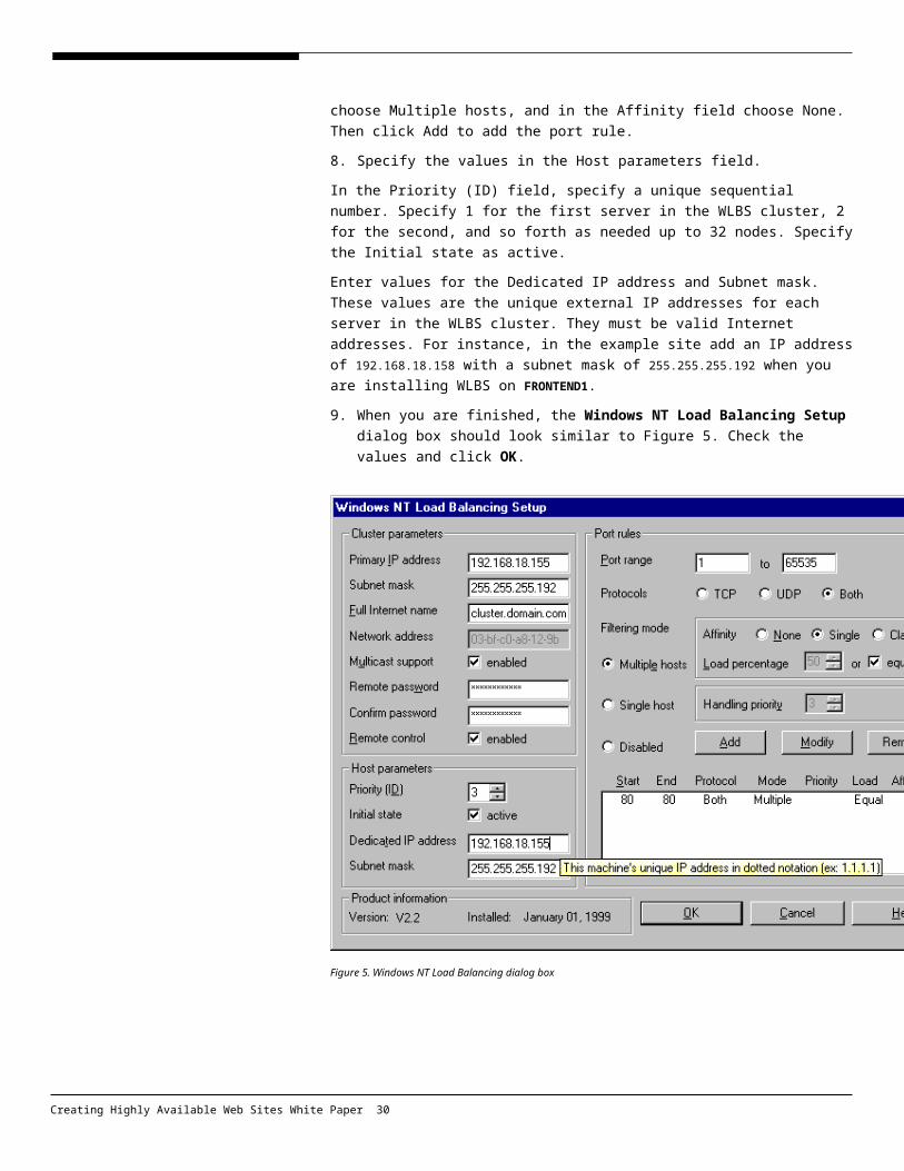
Enter 80 in both boxes of the Port range field. In the Protocols field, click Both. In the Filtering mode field, choose Multiple hosts, and in the Affinity field choose None. Then click Add to add the port rule.
8. Specify the values in the Host parameters field.
In the Priority (ID) field, specify a unique sequential number. Specify 1 for the first server in the WLBS cluster, 2 for the second, and so forth as needed up to 32 nodes. Specify the Initial state as active.
Enter values for the Dedicated IP address and Subnet mask. These values are the unique external IP addresses for each server in the WLBS cluster. They must be valid Internet addresses. For instance, in the example site add an IP address of 192.168.18.158 with a subnet mask of 255.255.255.192 when you are installing WLBS on FRONTEND1.
9. When you are finished, the Windows NT Load Balancing Setup dialog box should look similar to Figure 5. Check the values and click OK.
Creating Highly Available Web Sites White Paper 25

Figure 5. Windows NT Load Balancing dialog box
Configuring TCP/IP Settings on a WLBS HostTo configure TCP/IP settings on a WLBS Host
1. In the Windows NT Network dialog box, click the Bindings tab to view the bindings for all protocols.
2. Bind the WLBS Driver protocol to the WLBS Virtual NIC adapter and to the cluster adapter.
3. Unbind the WLBS Driver protocol from the dedicated adapter.
4. Bind the TCP/IP protocol and the WINS Client protocol to the WLBS Virtual NIC adapter.
5. Bind the TCP/IP protocol and the WINS Client protocol to the dedicated adapter.
6. Unbind the TCP/IP protocol and the WINS Client protocol from the cluster adapter.
7. Move the WLBS Virtual NIC adapter below the dedicated adapter in the list of adapters for the TCP/IP protocol and the WINS Client protocol.
8. The Bindings tabbed page of the Network dialog box is illustrated in Figure 6. In this case, the Compaq NIC is the cluster (outward-facing) adapter and the
Creating Highly Available Web Sites White Paper 26
3Com NIC is the dedicated (internal communications) adapter. Review the bindings and click OK.
Figure 6. Configuring TCP/IP settings
9. When prompted for an IP address for the Windows NT Load Balancing Service, enter the IP address of the server, subnet mask, and the gateway.
10. Click Advanced, and then enter the Ip address of the cluster.
11. Click OK, and Restart the server.
This concludes the installation of WLBS on a server. Repeat the procedure for each Web server in the front end.
Testing WLBSWhen you have finished installing WLBS on each of the front-end servers, perform the following tests to verify that the cluster is performing correctly:
Verify that you can ping the virtual IP address of the cluster. In this example, verify that you get a response when you ping 192.168.18.155.
Verify that you can ping each host in the front-end cluster. Put a slightly different default page in the wwwroot directory for each host and
Creating Highly Available Web Sites White Paper 27

repeatedly open the default Web page for the cluster (http://cluster.domain.com). You should see the different pages in quasi-random order as the individual servers in the cluster respond to the HTTP requests to the cluster. When you perform this test, make sure that caching is disabled on the client browser.
Verify that you do not get a response when you ping the IP addresses on the internal (10.0.0.x) network from a computer on an external network.
Installing Site Server Commerce Edition
First you must set up a database for Site Server, and then perform a standard installation of Site Server on each of the front-end servers.
To create a Data Source for Site Server
1. Install the Microsoft SQL Server 7.0 administrative tools on the staging server (STAGE1).
2. Start Microsoft SQL Server Enterprise Manager and register SQL1 and SQL2 as servers.
3. Navigate to Console Root/Microsoft SQL Servers/SQL Server Group/SQL1.
4. Right-click the Databases node and click New Database.
5. In the Name field, specify the name of the Site Server database. In this scenario, enter COMMERCE.
6. Click OK.
To create an ODBC link to the Site Server Database
The following steps must be performed on each front-end server:
1. In Control Panel, click the ODBC icon.
2. Click the System DSN tab, and then click Add.
3. Select the SQL Server driver, and click Finish.
4. The Create a New Data Source to SQL Server dialog box appears.
5. In the Name field, enter the name of the Commerce Server database. In this scenario, enter COMMERCE.
6. In the Description field, enter a descriptive comment.
7. In the Server field, enter the name of the SQL Server computer hosting the Commerce database. In this scenario, enter SQL2.
8. Click Next.
9. When How should SQL Server verify the authenticity of the login ID? appears, select With SQL Server authentication using a login ID and password entered by the user.
10. Select Connect to SQL Server to obtain default settings for the additional
Creating Highly Available Web Sites White Paper 28

configuration options and specify a valid Login ID and password. In this example, enter sa as the Login ID and leave the password field blank.
11. Click Next.
12. Select the Change the default database to: check box and change the default database to COMMERCE from MASTER.
13. Clear the Create temporary stored procedures check box.
14. Click Next twice to pass through the next two screens, and click Finish.
15. You should see a dialog box indicating that the new data source will be created. Review the settings for the data source and click OK.
To install Site Server
Site Server must be installed on each front-end server. Select the typical installation for Site Server.
To install Site Server Commerce Edition
The following steps must be performed on each front-end server:
1. Select Custom Setup.
2. Clear all optional components except Volcano Coffee Site.
3. When prompted to provide an ODBC DSN, specify COMMERCE.
4. Specify an account and password for the SQL Server database.
Mapping Front-end Web Site to Back-end Cluster Service File Share
The following procedure maps the local path of an IIS-based Web site to a share that is located on the back-end cluster. This mapping provides access to a common Web content store with failover capability in the event of a back-end server failure.
Configuring the Web Servers to Use the Back-end File ShareThis example will create a virtual directory off of the default Web site and map the virtual directory to the back-end file share. This must be repeated on all front-end servers to have this work consistently across the front end.
To configure a Web Server to Use the Back-end File Share
This procedure creates a mapping from an existing Web site to the back-end file share. The procedure must be repeated on each front-end server in order for the file share to appear consistently across the front end.
1. Open the Microsoft Management Console (MMC) for IIS (Start/Programs/Windows NT Option Pack/Microsoft Internet Information Server/Internet Services Manager).
2. Right-click the name of the server that will be mapped to the back-end share.
3. Click New, and select Web Site.
Creating Highly Available Web Sites White Paper 29
4. Enter a description for the Web site. In the example site, specify TESTSITE, and click Next.
5. Specify the IP address and the port number for the Web site. Click Next.
6. When prompted for the physical path for the home directory, click Browse.
7. Navigate to the WebContent share on BACKEND and click OK. (The WebContent share was created in the procedure described in “Creating a File Share in the Cluster.”)
8. Click Next.
9. Specify the security credentials that will be used for the network directory for this site. The credentials consist of a user name and a password.
Note that the user name specified in this step will be used for the security context for all access to the data from IIS to this share.
10. Specify the permissions for the Web site, and click Finish.
Analyzing Site Traffic Using Site ServerUse these steps to configure Site Server Usage Analysis as a repository to store information and create a report about site usage.
To configure IIS Logs
The first step of the process is to configure the IIS logs to record as much information as it can. This procedure must be repeated on each of the front-end Web servers.
1. Go to Start/Programs/Windows NT 4.0 Option Pack/Microsoft Internet Information Server/Internet Service Manager.
2. Navigate to Console Root / Internet Information Server / ComputerName / Default Web Site, right-click the site for which you want to configure the log, and then click Properties.
3. Click the Web Site tab, and make sure the Enable Logging box is checked. In the Active log format field, click W3 Extended log file format.
4. Click the Properties button in the Enable logging field, and then click the Extended properties tab.
5. Select all of the options.
6. Click OK twice.
7. Stop and restart IIS.
8. Open Windows Explorer and share the folder in which the logs are located. By default, this folder is %windir%\system32\logfiles.
Running Site Server Usage Analysis
Creating Highly Available Web Sites White Paper 30

The second step is to configure Site Server Usage Analysis to get the log files and process them into a useful report. This procedure is performed on the STAGE1 server.
To configure Site Server Usage Analysis
1. Go to Start/Programs/Microsoft Site Server/Analysis/Custom Import.
2. The first time that you run Usage Analysis you must specify a data source property. Click Microsoft IIS W3C extended log file format.
3. When you are prompted for the Server Properties, click OK.
4. You will be prompted for the Site Properties. Enter the URL of the site. In this example, specify http://cluster.domain.com and click OK.
5. In the Import Manager pane, click Browse.
6. Navigate to the usage log files you created on each of the front-end Web servers. In this example, the logs on the first Web server are stored on \\FRONTEND1\logfiles\W3svc1\filename. Select the log file and click Add to list. Repeat this step on all of the front-end Web servers until you have added all of the usage log files you want to analyze.
7. Close the Import Manager.
8. Go to Start/Programs/Microsoft Site Server/Analysis/Report Writer.
9. Select Report Writer Catalog. Click OK. Select Summary and then specify Executive summary report (extended logs).
10. Click Next and then click Run.
11. When you are prompted to specify a name for the page, enter Commerce, and click OK.
A report will be built, based on the log files you specified.
This section introduces the architecture for a highly available Web site using Windows 2000 technologies, and then provides step-by step-instructions showing how to build the servers and supporting infrastructure for an example site based on this architecture.
HardwareThe example site uses a total of six servers, all running Windows 2000 Advanced Server.
The hardware used in the example site may be considered as a baseline for a highly available system. Check with your hardware vendor for more information about hardware solutions for increased availability, such as dual interface Ethernet
Creating Highly Available Web Sites White Paper 31
BUILDING THE WINDOWS 2000-BASED HIGHLY AVAILABLE WEB SITE

adapters and uninterruptible power supplies.
When building a highly available site, it is recommended that you use hardware listed in the Windows 2000 Hardware Compatibility List (HCL).
Data Storage
Data storage for the Web site (the back end) is managed by two servers running Microsoft Cluster services with a Fibre Channel connection to a shared RAID level 5-disk array. The server cluster provides availability in the event of a server failure, and the RAID array provides availability in the event of a disk failure.
The disk technology provided in modern servers and arrays can detect potential disk failures before the failure happens. If a disk failure is predicted by the system, the failing disk can be hot swapped out of the RAID 5 array and replaced with no loss of service for the site. RAID 5 arrays can be implemented in software using built-in Windows 2000 Advanced Server services. However, the example site uses a hardware implementation for increased data access performance.
Networking
Each server has two 100-Mbps Ethernet network interface cards (NICs). The TCP/IP protocol is used throughout the example site.
In the back end servers running Cluster service, one NIC is connected to a private network (10.0.0.x) providing access to the Web servers through a 100-Mbps switch. The other NIC provides the cluster heartbeat mechanism and is connected to the other cluster server by way of an Ethernet crossover cable. This example uses a private network address for the cluster heartbeat network that uses the 11.0.0.x range of IP addresses.
In the front end servers providing Web services, one NIC is connected to a 100-Mbps switch that is connected to a network that routes to the Internet. This NIC is bound with a public IP address of 192.168.18.155. The other NIC is connected to the private network (10.0.0.x) through the 100-Mbps switch that interconnects the servers in the site.
Front-End and Back-End Tiers
The example site has a multi-tiered architecture that provides redundancy and fault tolerance for Web services. The architecture is physically divided into two main tiers, the front end and the back end. The front end provides the core Web services such as Microsoft Internet Information Services (IIS). The clustered back end provides data and Web content storage and database services. The data storage services are provided by a file share service with failover capability within the cluster. The database services are provided by Microsoft SQL Server 7.0, Enterprise Edition, running on the cluster in active-to-active mode.
Installation Overview It is important that the primary domain controller (PDC) that will be used for the high
Creating Highly Available Web Sites White Paper 32

availability site be set up first, and DNS properly configured, before setting up the front and back end nodes. This is because the Cluster nodes have to be installed as machines within a Windows 2000 domain, and because the DNS will provide machine/IP address name resolution for the internal network. In a live configuration, it is very important to have a backup domain controller (BDC) in order to create redundancy and avoid a single point of failure. The example site uses a PDC with no BDC, but this is not recommended for a production configuration.
Setting Up the Domain ControllerThe domain controller is a server running Windows 2000 Advanced Server. The only software that is required on this server is Windows 2000 Advanced Server. Throughout this document, this server will be referred to as STAGE1.
The following software will be installed on the domain controller:
Windows 2000 Advanced Server
Installing Windows 2000 Advanced Server for the Domain Controller
To install Windows 2000 Advanced Server for the domain controller
1. Run Setup for Windows 2000 Advanced Server.
2. When you are prompted for a server name, type STAGE1.
3. When you are prompted for adding a password for the user account administrator, add a valid password.
4. In the Windows 2000 Components dialog box, accept the default choices.
5. In the Network Settings dialog box, click Custom Settings.
6. Select the Internet Protocol (TCP/IP), and then click Properties.
7. In the Internet Protocol (TCP/IP) Properties dialog box, click Use the following IP address to specify a manual TCP/IP configuration.
8. In the IP addresses section, enter the following addresses for the internal and external networks, respectively. Note that after you configure the properties for a NIC during Windows 2000 Setup, and then click Next in the Network Components dialog box, you are prompted to configure the IP options for the second NIC. Network Settings:
10.0.0.6, with a subnet mask 255.0.0.0 for the Internal NIC 192.168.18.160, with a subnet mask of 255.255.255.192 for the External NIC Click the use the following DNS server addresses button and enter the
preferred DNS server IP address—10.0.0.6. Click the advanced button. Click the DNS tab, and enter the DNS suffix for the connection. (In this
example, we used commerce.yourdomain.com).
9. In the Workgroup Or Domain dialog box, click No, this computer is not on
Creating Highly Available Web Sites White Paper 33

the network or is a member of the following workgroup. Accept the default WORKGROUP and click Next.
10. Complete the installation of Windows 2000 Advanced Server, accepting the default settings, and restart the server.
11. Once the system has finished installing, log on to the server using an account with administrator privileges (the Administrator account).
12. Now the server must be configured as a domain controller and DNS server. To accomplish this do the following:
On the Start menu, click Run. In the Open dialog box, type dcpromo, and then click OK. The Active Directory Installation wizard starts, click Next to continue. Click Domain Controller for a New Domain, and then click Next. Click Create a New Domain Tree, and then click Next. Click Create new Forrest of Domain Trees, and then click Next. Enter the full DNS name for the new domain. This example uses
commerce.yourdomain.com. Then click Next. Accept the NetBIOS domain name (in this example it is COMMERCE), and then
click Next. Accept the default Database and Logs location, and then click Next. Accept the Shared System Volume location, and click Next. Click OK when prompted that the “wizard cannot locate the DNS server that
handles the name commerce.yourdomain.com. Confirm your DNS server or configure a DNS server on this computer”.
You will be prompted to set up a DNS server in the next steps.
In the Configure DNS dialog box, click Yes, install and configure a DNS server on this computer, and then click Next.
In the Win NT RAS Servers dialog box, click No, do not change NT permissions, and then click Next.
Enter a valid Administrator account password, and then click Next. Accept the Summary settings, and click Next. This starts the creation of the
Windows 2000 domain and installs the DNS server on Stage 1. When the setup is complete, click Finish to restart the server.
This concludes installation of Windows 2000 Advanced Server on the domain controller.
Configuring DNS on the Stage1 Server
The example site uses the DNS server on STAGE1 for name resolution on the internal network. In this part of the procedure, you configure the DNS server on STAGE1.
To configure DNS on the Stage 1 Server
1. On the Start menu, point to Programs, then to Administrative Tools, and
Creating Highly Available Web Sites White Paper 34

click DNS. This starts the MMC console that manages DNS services.
2. On the DNS menu, click New Server.
3. Right click the computer name that you are using (Stage1), and select New Zone. This starts the New Zone wizard. Click Next in the first wizard dialog box.
4. Click Standard Primary, and then click Next.
5. Click Forward Lookup Zone, and click Next.
6. In the Zone Type field, specify Primary, and click Next.
7. In the Zone Name field, specify commerce.yourdomain.com, and then click Next.
8. Ensure that Create a new file with this file name is selected, and then click Next.
9. Click Finish to create the Zone.
10. Right-click the commerce.yourdomain.com zone, and click New Host.
11. Add the following hosts.
Host Name IP Address
FRONTEND1 10.0.0.1
FRONTEND2 10.0.0.2
FRONTEND3 10.0.0.3
COMCLUSTER1 10.0.0.4
COMCLUSTER2 10.0.0.5
STAGE1 10.0.0.6
SQL1 10.0.0.7
SQL2 10.0.0.8
BACKEND 10.0.0.9
Setting Up the Back End ServersThe two back end servers are set up as a cluster using a shared RAID data store. They provide data storage for the example site. For a database driven Web site (such as an e-commerce Web site based upon Microsoft Commerce Server), the back end provides an active-to-active SQL Server nodes.
For the most part, both servers can be set up concurrently. However, where noted, you must perform configuration steps on one server before you can take the corresponding step on the other server.
The following software will be installed on the back end servers:
Windows 2000 Advanced Server
Creating Highly Available Web Sites White Paper 35

SQL Server 7.0
Installing Windows 2000 Advanced Server for the Back-End Servers
Windows 2000 Advanced Server will be installed on the two servers that will make up the back end of the example site.
To install Windows 2000 Advanced Server for the back-end servers
1. Run Setup for Windows 2000 Advanced Server. Note that Microsoft Internet Information Server will be installed as part of the default server installation.
2. When you are prompted for a server name, specify COMCLUSTER1 on the first server and COMCLUSTER2 on the second server.
3. In the Workgroup Or Domain dialog box, click Yes, make this computer a member of the following domain, and enter a valid Windows 2000 domain name. (In this example, use COMMERCE).
4. In the Join Computer to the Commerce Domain dialog box, enter a valid domain user name and password with domain administrator privileges.
5. DHCP is not used in the example site, so specify manual TCP/IP configuration.
6. When prompted for IP addresses, enter the following addresses for the internal and heartbeat networks. Specify a subnet mask of 255.0.0.0 for each IP address.
Server COMCLUSTER1 COMCLUSTER2
NIC #1 (internal) IP 10.0.0.1 10.0.0.2
NIC #2 (cluster heartbeat) IP 11.0.0.1 11.0.0.2
Enter the following network configuration parameters for each of the two back end servers:
Click Use the Following DNS Server Addresses, and enter the preferred DNS server IP address—10.0.0.6.
Click Advanced.
Click the DNS tab. Type the DNS suffix for the connection (In this example, we used commerce.yourdomain.com.)
In the DNS Service Addresses in order of use field, specify two DNS servers, in the following order:
1. The first DNS server is the STAGE1 DNS server, for internal name resolution. It has an IP address of 10.0.0.6.
2. The second DNS server will be the Internet DNS server used for your network. For purposes of this example, a DNS server with an IP address of 192.168.18.194 will be specified.
7. Complete the installation of Windows 2000 Advanced Server, accepting the
Creating Highly Available Web Sites White Paper 36

default settings, and restart the server.
8. Verify that you have network connectivity between all computers in the example site. You should be able to ping each server by name.
9. Check the Event Viewer logs to see if there are any unexpected messages.
This concludes the installation of Windows 2000 Advanced Server on the back end servers.
Installing RAID Support
Fibre Channel SCSI support must be installed on both back end servers so they can access the shared disk array. It is important for the array to be configured as RAID 5 to gain redundancy. Consult the documentation from your hardware manufacturer for more information about how to do this.
1. Power down COMCLUSTER2. Keep it powered down until step 5 in this procedure. It is important that only one server have access to the array while it is being configured.
2. Start Disk Administrator (On the Start menu, point to Programs, and then to Administrative Tools, and then click Disk Administrator).
3. The array used in the example site has 12 physical disk drives that will be configured as four logical drives, each a RAID 5 array.
4. Configure the logical disks as follows.
Disk Letter Notes
1 W: Used by Cluster service to store cluster information (quorum resource)
2 X: SQL1: Stores all the data for Microsoft server cluster Node 1
3 Y: SQL2: Stores all the data for Microsoft server cluster Node 2
4 Z: Shared resource used by the front end for Web content storage
5. Power down COMCLUSTER1 and start COMCLUSTER2.
6. Run Disk Administrator, and assign drive letters as shown in step 4.
7. Start COMCLUSTER1.
8. Verify that both back end servers have access to the shared disk array.
9. Create an Emergency Repair Disk for each back end server.
Installing Cluster Services on COMCLUSTER1
To install Cluster services on COMCLUSTER1
1. To start the installation of Microsoft Cluster services, double-click Add/Remove Programs in Control Panel.
2. Click Add/Remove Windows Components.
Creating Highly Available Web Sites White Paper 37

3. Select the Cluster Service check box to enable Cluster services, and then click Next.
4. In the Welcome page, click Next.
5. In the Hardware Configuration page, click I understand, and then click Next.
6. Click he First Node in the cluster, and click Next.
7. In the Type the name for the new cluster field, specify a name to identify the cluster. (In this scenario, it is BACKEND.) Then click Next.
8. Enter the user name, password, and domain for the account the Cluster service will run under, and then click Next. (Administrator is used as the user name in the example site, but in a production environment, for security reasons, you should use a less obvious administrative account name.)
9. In the Add Or Remove Managed Disk dialog box, add or remove the disks on the RAID data store that you will use with your cluster, and then click Next. (In the example site, all of the disks were added to the cluster.
10. In the Cluster File Storage, click the name of the disk on the RAID data store on which you want to store the quorum resource, and then click Next. (In this example, the quorum resource was stored on the W: drive.) You can store the quorum resource on any shared physical disk array
11. In the Configuration Cluster Network dialog box, click Next to allow Setup to identify all network resources that are available on your server.
12. For each network adapter installed in the node, specify:
A name that describes the network, using a meaningful description so you can identify the networks when working in Cluster Administrator.In this scenario, give the name internal to the 10.0.0.x network. Select Use only for client access.
Specify the name heartbeat for the 11.0.0.x network (used by the cluster for heartbeat communication keeping the cluster information updated). Select Use only for internal cluster communication. Click Next.
In the Cluster IP Address box, enter the static IP address and subnet mask that you want to use to identify the cluster. In this scenario, the IP address is 10.0.0.9 and the subnet mask is 255.0.0.0.
In the Network dialog box, click Internal, and click Next when you are finished.
13. Click Finish, and then click OK in the message that explains that the cluster has been set up successfully
Installing Cluster Server on COMCLUSTER2
1. COMCLUSTER1 must be up and running before you start the cluster installation on COMCLUSTER2.
Creating Highly Available Web Sites White Paper 38

2. To start the installation of Microsoft Cluster service, in Control Panel, double click Add/Remove Programs.
3. Click Add/Remove Windows Components.
4. To enable the Cluster service, select the Cluster Service check box, and then click Next.
5. In the Welcome page, click Next.
6. In the Hardware Configuration page, click I understand, and then click Next.
7. Click Second or Next Node in the Cluster, and click Next.
8. In the Cluster Name dialog box, type the name of the cluster that you want to join. Specify the cluster BACKEND, and then click Next.
9. Enter the password for the domain user account you specified when installing COMCLUSTER1, and then click Next.
10. Click Finish, and then click OK.
Verifying the Cluster Installation
You can verify the installation of your cluster by starting Cluster Administrator and checking that both nodes in your cluster are detected.
On either node, on the Start menu, point to Programs, then to Administrative Tools, and then click Cluster Administrator to make sure that both nodes show up.
Installing SQL Server
There are two ways to set up SQL Server in a cluster environment: active-to-active and active-to-passive. In this scenario, active-to-active clustering is used.
In an active-to-passive cluster, one server handles all of the SQL queries while the other waits for the first server to fail so it can take ownership of the cluster resources. This configuration is sometimes referred to as hot standby.
In an active-to-active cluster, both servers respond to SQL queries. The database must reside on a shared disk array. Note that two servers cannot access the same resources at the same time.
An example of an active-to-active cluster is when the first SQL Server computer responds to Commerce Server queries and the second SQL Server computer responds to queries on a custom application database. This is the configuration used in this example site.
To install SQL Server in the cluster 1. In this example, the SQL Server installation on COMCLUSTER1 will use the X:
drive for the SQL Server program files, the data, and the log files. No parts of SQL Server are installed on local hard drives on either back end server.
2. Select Local Installation. (The installation is local, but the location of the files
Creating Highly Available Web Sites White Paper 39

will not be local.) Then click Next.
3. Choose Typical Installation.
4. Install SQL Server on a shared disk array. Make sure the disk group is owned by the server cluster in which SQL Server is installed. In this example, SQL Server is installed on COMCLUSTER1 on the X: drive, which is owned by COMCLUSTER1. Similarly, SQL Server is installed on COMCLUSTER2 on the Y: drive, which is owned by COMCLUSTER2.
5. In the Service Account dialog box, select Customize the settings for each service.
6. Click SQL Server, and enter an administrative user name and password.
7. Verify that Autostart services is not enabled.
8. Click SQL Server Agent, and enter the administrative user name and password.
9. Click Next.
10. Click Next.
11. Repeat these steps for COMCLUSTER2 after COMCLUSTER1 has restarted. Install SQL Server on COMCLUSTER2 on the Y: drive.
Creating the SQL Server Cluster
This procedure sets and configures SQL to be cluster-enabled. You must log on to the computer with administrative right to it . In addition, the account must have the Act as part of the operating system right.
1. Make sure no applications are running on either back end server. This includes applications running in the system tray in the taskbar, such as SQL Service Manager).
2. Open the Failover Cluster wizard (Start/Programs/SQL Server 7.0/Failover Cluster wizard) and click Next.
3. Select Install Virtual Server, and click Next.
4. Enter the SQL Server administrative account and password. Click Next.
5. Enter the SQL User account password . Click Next.
6. Enter the IP address for the SQL Server cluster. This IP address must be unique on the private network. In this example, use an IP address of 10.0.0.7 with a subnet mask of 255.0.0.0. Click Next.
7. Specify a name for the SQL Server cluster. In this example, the cluster owned by COMCLUSTER1 is named SQL1, and the cluster owned by COMCLUSTER2 is named SQL2.
8. Click Finish.
Creating Highly Available Web Sites White Paper 40
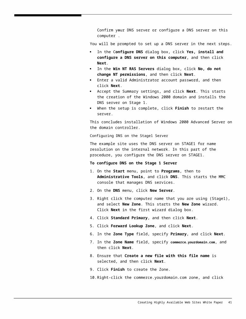
9. Restart the other server in the back end cluster. That is, after you install the SQL Server cluster on COMCLUSTER1, you must restart COMCLUSTER2.
10. Repeat these steps for COMCLUSTER2.
11. Open Cluster Administrator, right-click the cluster resource groups (SQL1 and SQL2), and then specify that they should be brought online.
Configuring Microsoft Cluster Service
1. Open Cluster Administrator and delete all of the empty groups. On the Start menu, point to Programs, then to Administrative Tools, and click Cluster Administrator.
2. To allow a specific owner for a specific group, right-click the group and open the Properties page, and click Modify.
3. In the Preferred owner field, specify the following values:
Cluster Group Both
SQL1 COMCLUSTER1
SQL2 COMCLUSTER2
4. To allow failover and failback for a group, right-click the group, and open the Properties dialog box. Click the Failback tab, select Allow Failback , and then click Immediately.
5. Click OK.
Creating a File Share in the Cluster
The procedure in this section creates a common file storage resource on the back end for use by the front end. This back end file share will be used to store all of the Web site content and has the capability to fail over from one cluster node to the other in the case of a node failure.
1. Open Cluster Administrator and navigate to the cluster group node.
2. To add the last hard drive (Z:) to the cluster group, open the Resource folder in the right pane, select Drive Z:\ and drag and drop it into the cluster group.
3. Create a new resource in the cluster group (right-click the cluster group).
4. Specify the following values, and then click Next.
Name WebContent
Resource type File share
Group Cluster Group
5. Both nodes are going to be possible owners. Click Next.
6. Add the cluster name (BACKEND) and disk drive (Z:) as dependencies of the WebContent resource. Click Next.
7. Specify the following values, and then click Finish.
Creating Highly Available Web Sites White Paper 41

Share Name WebContent
Path Z:\
8. Right-click the name of the WebContent resource and bring it online.
Setting Up the Front EndThe three Web servers in the front end are set up as a cluster using Windows 2000 Advanced Server Network Load Balancing (NLB). They respond to HTTP requests from users on the Internet.
For the most part, the servers can be set up concurrently. However, where noted, there are configuration steps that must be performed on one server before the corresponding step can be taken on the other servers.
The procedures in this section can be repeated to add up to 32 servers to the front-end cluster. The current limit is 32 servers in a single cluster.
The following software will be installed on each of the front-end servers:
Windows 2000 Advanced Server
Installing Windows 2000 Advanced Server
Windows 2000 Advanced Server is installed on the three Web servers in the front end of the example site.
To install Windows 2000 Advanced Server in the front end
1. Run Setup for Windows 2000 Advanced Server. Note that Microsoft Internet Information Services are installed as part of the default server installation.
2. When you are prompted for a server name, specify FRONTEND1 on the first server, FRONTEND2 on the second, and FRONTEND3 on the third.
3. In the Workgroup Or Domain dialog box, click Yes, make this computer a member of the following domain, and enter a valid Windows 2000 domain name (in this example use COMMERCE.)
4. In the Join Computer to the Commerce Domain dialog box, enter a valid domain user name and password with domain administrator privileges.
5. DHCP is not used in the example site, so specify manual TCP/IP configuration.
6. When prompted for IP addresses for each of the three front end servers, enter the following addresses for the internal and external networks.
Server FRONTEND1 FRONTEND2 FRONTEND3
NIC 1 (internal) 10.0.0.1 10.0.0.2 10.0.0.3
NIC 2 (external) 192.168.18.158 192.168.18.159 192.168.18.160
Enter the following network configuration parameters for each of the three front end servers:
Creating Highly Available Web Sites White Paper 42

Specify a subnet mask of 255.0.0.0 for each IP address on the internal network.
For the external network, specify a subnet mask appropriate for your network. In this example, a subnet mask of 255.255.255.192 is used for the external network.
Click the Use the Following DNS Server Addresses button, and enter the preferred DNS server IP address—10.0.0.6.
Click Advanced.
Select the DNS tab. enter the DNS suffix for the connection. (In this example, we used commerce.yourdomain.com.)
In the DNS Service Addresses, in order of use field, specify two DNS servers, in the following order:
1. The first DNS server is the STAGE1 DNS server, for internal name resolution. It has an IP address of 10.0.0.6.
2. The second DNS server will be the Internet DNS server used for your network. For purposes of this example, a DNS server with an IP address of 192.168.18.194 will be specified.
7. Complete the installation of Windows 2000 Advanced Server, accepting the default settings, and restart the server.
8. Verify that you have network connectivity between all computers in the example site. You should be able to ping each server by name.
9. Check the Event Viewer logs to see if there are any unexpected messages.
This concludes the installation of Windows 2000 Advanced Server on the front end servers.
Installing Windows 2000 Network Load Balancing
Note: In this section, and in NLB documentation, a group of servers running NLB is referred to as a cluster. However, in this context, the front end cluster is not a group of servers running the Microsoft Cluster service.
There are two main steps to setting up the NLB:
Installing and configuring the NLB components. Configuring the TCP/IP settings on the server.
These steps must be performed on each server that will join the cluster.
Required Information and ComponentsTo install the NLB components, you will need the following:
The full Internet name that you plan to use for the cluster. In this scenario, the name of the cluster is commerce.yourdomain.com.
The IP address that you plan to use for the cluster. This IP address is
Creating Highly Available Web Sites White Paper 43

sometimes referred to as the virtual IP of the cluster. The same cluster IP address is used on all hosts in the cluster. It must be a valid IP address that is unique on the Internet. In this scenario, the following address is used: 192.168.18.155.
The IP address for the external-facing NIC in each cluster host. This NIC is sometimes referred to as the cluster adapter. The cluster adapter IP address is unique to each host, and must be unique on the Internet. It is used for communications with the individual host (not the cluster as a whole), such as during content deployment.
Note: If you are using a router to connect a NLB cluster to its clients, be sure that the router has its proxy Address Resolution Protocol (ARP) support enabled. This allows the router to map the cluster's primary IP address and other multi-homed addresses to the corresponding media access control (MAC) address. If your router does not route to the cluster with proxy ARP support enabled, you can also create a static ARP entry in the router. Cisco routers require a static ARP entry because they do not support proxy ARP for multicast MAC addresses.
Installing and Configuring NLBTo install and configure NLB, follow these steps for each host to be used in your NLB cluster.
To install and configure NLB
1. In Control Panel, double-click the Network and Dial-Up Connections icon.
2. Right click the local area connection that is configured for the external NIC, and then click Properties.
3. Click Install.
4. In the Network Component Type dialog box, click Service, and then click Add.
5. Select Network Load Balancing, and click OK.
6. Select the Network Load Balancing checkbox, and then click Properties .
7. The Network Load Balancing Properties dialog box appears. Now specify the cluster parameters. The following values are used for the example site.
Parameter Value
Primary IP address 192.168.18.155
Subnet mask 255.255.255.192
Full Internet name commerce.yourdomain.com
Multicast support enabled
Remote password password
Remote control enabled
Warning: If you enable remote control for your NLB cluster (disabled by default), it is vital, for reasons of security, that you firewall the NLB UDP control port (the port receiving remote-control commands) in
Creating Highly Available Web Sites White Paper 44

order to shield it from outside intrusion. By default, this is port 2504 at the cluster IP address.
8. Click the Host Parameters tab.
9. Specify the values in the Host parameters fields.
In the Priority (ID) field, specify a unique sequential number. Specify 1 for the first server in the NLB cluster, 2 for the second, and so forth as needed up to 32 nodes. Specify the Initial state as active.
Enter values for the Dedicated IP address and Subnet mask. These values are the unique external IP addresses for each server in the NLBS cluster. They must be valid Internet addresses. In the example site, add an IP address of 192.168.18.158 with a subnet mask of 255.255.255.192 when you are installing NLB on FRONTEND1.
10. Create port rules to specify how you want NLB to handle network traffic for specific ports. In this scenario, Web access is only provided to the front end, so only port 80 is enabled (for HTTP).
Highlight the default port rule (0-65535)
Change port range to 80 to 80.
Set Affinity to none (there will be no affinity settings for port 80 in this example).
Click Modify, and then click OK.
11. Click Close to close the Local Area Connection Properties dialog box.
12. Repeat these steps for each of the front end servers. (Use IP address 192.168.18.159 with a subnet mask of 255.255.255.192 when you install NLB on FRONTEND2 and 192.168.18.160 with a subnet mask of 255.255.255.192 when you are installing NLB on FRONTEND3)
Testing Network Load BalancingWhen you have finished installing NLB on each of the front end servers, perform the following tests to verify that the cluster is performing correctly:
Verify that you can ping the virtual IP address of the cluster. In this example, verify that you get a response when you ping 192.168.18.155.
Verify that you can ping each host in the front end cluster. Put a slightly different default page in the wwwroot directory for each host and
repeatedly open the default Web page for the cluster (http://commerce.yourdomain.com). You should see the different pages in quasi-random order as the individual servers in the cluster respond to the HTTP requests to the cluster. When you perform this test, make sure that caching is disabled on the client browser.
Verify that you do not get a response when you ping the IP addresses on the internal (10.0.0.x) network from a computer on an external network.
Creating Highly Available Web Sites White Paper 45

The links below contain more information, resources, and downloadable material relating to creating highly available Web sites.
Exploring Windows Clustering Technologies
Hardware Compatibility List
Internet Explorer 5
Lights Out Operation Guide for Microsoft Windows NT Server
Site Server 3.0 Commerce Edition
Site Server 3.0 Service Pack 2 installation files
Site Server 3.0
SQL Server 7.0
Tuning IIS for High-Volume Sites
Windows NT 4.0 Option Pack 4
Windows NT 4.0 Post Service Pack 4 Year 2000 Update
Windows NT 4.0 Service Pack 3
Windows NT 4.0 Service Pack 4
Windows NT Server, Enterprise Edition
Windows 2000 Server
Creating Highly Available Web Sites White Paper 46
FOR MORE INFORMATION