creating innovative and reliable circuits using inventive ... · exploit the potential performance...
TRANSCRIPT

Creating Innovative and Reliable Circuits Using Inventive Topologies and Semiconductors (CIRCUITS) Program Overview B. PROGRAM OVERVIEW
1. Summary Development of advanced power electronics with unprecedented functionality, efficiency, reliability, and form factor will help provide the U.S. a critical technological advantage in an increasingly electrified world economy. The CIRCUITS (Creating Innovative and Reliable Circuits Using Inventive Topologies and Semiconductors) program seeks to accelerate the development and deployment of a new class of efficient, lightweight, and reliable power converters based on wide bandgap (WBG) semiconductors through transformational system-level advances that enable effective operation at high switching frequency, high temperature, and low loss. Previous efforts by ARPA-E and others have primarily focused on WBG material and device development without focused consideration and redesign of the circuit topology. Such solutions do not fully exploit the potential performance improvements enabled by this new class of power semiconductor devices. Areas of particular interest for the CIRCUITS program include novel circuit topologies, advanced control and drive electronics, and innovative packaging. Such technological breakthroughs would catalyze the adoption of higher performance power converters in various critical applications (motor drives, automotive, power supplies, data centers, aerospace, ship propulsion, rail, distributed energy, and the grid) that offer significant direct and indirect energy savings and emissions reductions across electricity generation, transmission and distribution, and load-side consumption. Coupling novel and advanced circuit topologies with leading edge materials such as WBG semiconductor devices has the capacity to catalyze disruptive improvements for power electronics and subsequently for the U.S. economy.
2. Background
Electricity generation currently accounts for 40% of primary energy consumption in the U.S.,1 and over the next 25 years is projected to increase more than 50% worldwide.2 Electricity continues to be the fastest growing form of end-use energy. Power electronics are responsible for controlling and converting electrical power to provide optimal conditions for transmission, distribution, and load-side consumption. Estimates suggest that the fraction of electricity processed through power electronics could be as high as 80% by 2030 (including generation and consumption), approximately a twofold increase over the current proportion.3 Development of advanced power electronics with exceptional efficiency, reliability, functionality, and form factor will provide the U.S. with a competitive advantage in deployment of advanced energy technologies. Additionally, widespread integration of innovative converters offers substantial energy saving opportunities both directly, by inherently more efficient designs, and indirectly, by facilitating higher levels of adoption for fundamentally higher performing materials. High impact opportunities exist across a variety of applications, including: Motor Drives: Across all sectors, electric motors account for approximately 40% of total U.S. electricity demand.4 It is estimated that 40-60% of currently installed electric motors could benefit from variable frequency drives (VFDs),5 which enable efficient adaptation to speed and torque demands. Depending on the application, incorporation of VFDs can reduce energy consumption by 10-30%.6 Conventional VFDs for high power applications are bulky and occupy significant space. Power density and efficiency can be improved, and the overall system cost reduced, by using WBG-based VFDs.
1 U.S. Energy Information Administration, Monthly Energy Review (March, 2015) 2 U.S. Energy Information Administration, International Energy Outlook 2016 (May, 2016) 3 L.M. Tolbert, et al. Power Electronics for Distributed Energy Systems and Transmission and Distribution Applications: Assessing the Technical Needs for Utility Applications. Oak Ridge, TN: Oak Ridge National Laboratory (2005) 4 Waide, P.; Brunner, C. U. Energy-Efficiency Policy Opportunities for Electric Motor-Driven Systems. IEA (2011) 5 Energy Efficiency Roadmap for Electric Motors and Motor Systems. Energy Efficient End-use Equipment, IEA (2015) 6 Energy Efficiency and Power Electronics. Danfoss, ATV Seminar, March 1, 2012
2 CIRCUITS Program Overview
Automotive: Power electronics such as traction inverters, DC boost converters, and on-board battery chargers are critical elements in hybrid and electric vehicles (EVs), impacting energy efficiency in two ways: directly through switching and other losses, and indirectly by adding volume and weight. WBG inverters can reduce both direct and indirect losses by operating at higher switching frequencies, efficiencies, and temperatures.7 As a result, 15% improvement in energy efficiency has been predicted for representative hybrid EVs employing SiC traction inverters, with even larger energy savings possible given greater degrees of drivetrain electrification.8 Assuming aggressive market adoption of EVs in the U.S., use of WBG vehicle power electronics could save as much as 1 quadrillion Btu per year by 2050 relative to conventional Si-based systems.9 Additionally, efficient, lightweight, and low-cost DC fast charging infrastructure (≥120 kW) enabled by WBG converters will advance the commercial viability of EVs, which, in conjunction with a cleaner electricity generation portfolio, has the potential to significantly reduce the one quarter of total U.S. greenhouse gas emissions that stem from the transportation sector.10 Data Centers: Energy consumption in data centers accounts for approximately 2% of electricity use in the U.S.11 The power delivery architecture of most modern data centers consists of a line frequency transformer, low voltage power distribution network, centralized backup unit, and inefficient voltage regulators.12 Strategies to improve energy efficiency range from integration of lower loss power converters to complete redesign of the power delivery network.13 The latter approach often involves converting higher voltages at the rack level, where space is limited and proper thermal management is imperative, to reduce transmission losses and the number of conversion stages. High power density converters based on WBG devices can be key enablers for these more efficient systems, and operation at higher temperature can reduce cooling loads and further boost data center grid-to-chip efficiency. Aerospace: Longer, thinner, and lighter wings can reduce fuel consumption and carbon emissions by 50% relative to current commercial aircraft.14 Such a reduction would save approximately 1 quadrillion Btu of energy per year across the U.S. fleet at current demand.15 Achieving this transformative wing design requires electromechanical actuators that are small and lightweight with robust operation over a wide temperature range.16 Moreover, electrification of environmental controls, fuel pumps, brakes, and de-icing systems can further reduce weight and increase efficiency through elimination of engine bleed and pneumatic/hydraulic systems.17 WBG-based converters, with high gravimetric and volumetric power density and high temperature operation, offer a pathway to achieving significant energy savings in air transport by reducing weight in more-electric aircraft and enabling new paradigms in body design. Distributed Energy Resources: In grid applications, such as solar photovoltaic (PV) and wind, as well as the emerging fields of high voltage direct current (HVDC) and flexible alternating current transmission systems (FACTS), power conditioners are required to process and control the flow of electricity by supplying voltages and currents in a form that is optimally suited to the load. Power electronics are responsible for a loss of approximately 4% of all of the electricity generated in these applications and are the dominant point of failure for installed systems. For instance, a typical maximum
7 Hamada, K. et al. SiC-Emerging Power Device Technology for Next-Generation Electrically Powered Environmentally Friendly Vehicles. IEEE Transactions On Electron Devices (2015) 8 Zhang, H. et al. Impact of SiC Devices on Hybrid Electric and Plug-In Hybrid Electric Vehicles. IEEE Transactions on Industry Applications (2011) 9 U.S. Department of Energy. Quadrennial Technology Review (2015) 10 Williams, J.H. et al. Pathways to Deep Decarbonization in the United States (2014) 11 Shehabi, A. et al. United States Data Center Energy Usage Report. Berkeley, CA: Lawrence Berkeley National Laboratory (2016) 12 Zhabeloval, G. et al. Data center energy efficiency and power quality: an alternative approach with solid state transformer. 41st Annual conference of the IEEE Industrial Electronics Society (2015) 13 Candan, E. et al. A Series-Stacked Power Delivery Architecture with Isolated Differential Power Conversion for Data Centers. IEEE Transactions On Power Electronics (2016) 14 Slimmed Down Aircraft Wing Expected to Reduce Fuel and Emissions by 50%. NASA, accessed November 29, 2016, https://www.nasa.gov/image-feature/ames/slimmed-down-aircraft-wing-expected-to-reduce-fuel-and-emissions-by-50 15 Transportation Energy Data Book. Oak Ridge National Laboratory, 35th edition (2016) 16 Thin-Wing Electromechanical Actuation (EMA) Demonstration. Department of Defense Air Force Research Lab. 17 Wheeler, P. The More Electric Aircraft: Why Aerospace Needs Power Electronics. Accessed November 29, 2016, http://www.lboro.ac.uk/microsites/research/iemrc/Events%20write%20up/Power%20Electronics%2014.05.09/More_Electric_Aircraft_000.pdf
3 CIRCUITS Program Overview
conversion efficiency for a silicon-based PV inverter is approximately 96% (AC output/DC input),18 which drops significantly at operating temperatures above 50 °C. Novel WBG electronic circuits present a route to lower system-level costs by operating at higher switching frequencies that reduce the size of passive components and lower the overall system footprint. In addition, WBG circuits will increase system-level efficiency by allowing PV arrays to operate at higher voltages (e.g. medium voltage levels), enabling DC systems with fewer voltage conversions/transformers, replacing traditional combiner boxes with DC/DC converters, eliminating the need for on-site AC transmission lines, and ultimately allowing easier integration of energy storage solutions in the central substation. Together with a higher semiconductor operating temperature, the advantages of WBG electronics offer a pathway to more robust power converters with mean time to failure (MTTF) commensurate to the generation system lifetime (PV, wind, etc.). This will lower the equipment replacement cost and total plant O&M and have a significant impact on the levelized cost of energy in distributed resource applications. The vast majority of current power electronics utilize silicon power semiconductors (e.g., insulated gate bipolar transistors (IGBTs)) that are slower, less energy efficient, and more constrained in operating temperatures than devices fabricated from WBG semiconductors, such as SiC and GaN, due to fundamental differences in material properties. Higher critical electric fields in WBG materials (Ebr ≥ 200 V/µm) enable thinner, more highly doped voltage-blocking layers in the associated devices, which can reduce on-resistance by two orders of magnitude in majority carrier architectures (e.g., Metal Oxide Field Effect Transistors, MOSFETs) relative to Si (Ebr = 30 V/µm). 19 To mitigate conduction losses, high-voltage Si MOSFETs have large footprints that cause sizeable gate capacitance and substantial losses at high switching frequencies. Si IGBTs achieve smaller die footprints than MOSFETs by utilizing minority carriers and conductivity modulation, but the useful range of switching frequencies remains limited due to the relatively long lifetime of minority carriers. The inverse proportionality between switching frequency and passive component capacity results in low frequency silicon-based power converters with large form factors. High breakdown electric fields, low conduction losses, and short carrier lifetimes mean that WBG materials can achieve the same blocking voltage and on-resistance with a smaller footprint and at much higher frequency than a comparable Si device. The low intrinsic carrier concentration of WBG materials (ni ≤ ~10-9 cm-3) enables robust high-temperature performance due to low leakage currents at elevated temperatures. WBG semiconductors therefore provide a pathway to overcome the fundamental performance tradeoffs between blocking voltage, on-resistance, and switching frequency inherent to Si devices, enabling design of faster, more efficient, lighter, and smaller power converters with reduced cooling requirements. Substantial technical progress has been made on WBG-based power switches over the past decade. Investments from the Department of Defense20 and several DOE offices, including the Advanced Manufacturing Office,21 the Office of Electricity Delivery and Energy Reliability GIGA program,22 and the Vehicle Technologies Program,23 have helped build early U.S. leadership and bring WBG devices closer to widespread adoption. ARPA-E’s Agile Delivery of Electrical Power Technologies (ADEPT) program, initiated in 2010, funded several teams to develop new WBG devices and demonstrate their efficacy in system demonstrations.24 The ADEPT program successes were significant in advancing commercial applications of SiC and GaN devices. However, SiC and GaN device technologies have remained immature relative to Si and currently carry a substantial cost premium, limiting their widespread adoption.25 Many of the largest opportunities for increased energy efficiency and reduced energy-related emissions exist in extremely
18 SMA Technical Information, Efficiency and Derating, WKG-Derating-US-TI-en-15, Version 1.5, 2016 19 Heffner, A. et al. Recent Advances in High-Voltage, High-Frequency Silicon-Carbide Power Devices. Industry Applications Conference, 41st IAS Annual Meeting (2006) 20 “DARPA Sets Tough Goals For The Wide-Bandgap Community,” Compound Semiconductor, November 8, 2002 21 Office of Energy Efficiency and Renewable Energy, Advanced Manufacturing Office, “Wide Bandgap Semiconductor for Clean Energy Workshop: Summary Report,” (Washington, DC: U.S. Department of Energy, 2012) 22 Controlling the Flow: Next‐Generation Power Electronics Systems for Tomorrow’s Electric Grid. Office of Electricity Delivery and Energy Reliability (2015) 23 Office of Energy Efficiency and Renewable Energy, Vehicle Technologies Program, Multi-Year Program Plan 2011-2015, December 2010 (Washington, DC: U.S. Department of Energy) 24 “Agile Delivery of Electrical Power Technologies,” ARPA-E, U.S. Department of Energy, accessed Nov. 28, 2016, http://arpa-e.energy.gov/?q=arpa-e-programs/adept 25 R. Eden, “Market Forecasts for Silicon Carbide & Gallium Nitride Power Semiconductors,” Presentation at 2013 Applied Power Electronics Conference and Exposition, Long Beach, CA (March 2013)
4 CIRCUITS Program Overview
cost-conscious industries, including markets for railway traction drives, automotive applications, and industrial motors.26,27,28 By the end of the ADEPT program, cost still remained a major barrier to the widespread adoption of WBG devices despite opportunities for superior performance. ADEPT’s successor program, Strategies for Wide Bandgap, Inexpensive Transistors for Controlling High-Efficiency Systems (SWITCHES), launched in 2013 and was designed to address key materials fabrication and architecture issues that drive costs for SiC and GaN devices, as well as evaluate early stage WBG power semiconductors such as diamond.29 The goal was to enable the development of high voltage (>1200 V), high current (100 A) single die power semiconductor devices that, upon ultimately reaching scale, would have the potential to reach functional cost parity with silicon power transistors while also offering breakthrough relative circuit performance (low losses, high switching frequencies, and high temperature operation). These transformational technologies would reduce the barriers to ubiquitous deployment of low-loss WBG power semiconductor devices in stationary and transportation energy applications. One key target for the SWITCHES program is for WBG packaged devices to demonstrate a manufacturing cost of 0.1 $/A at 100A and 1200V, at which point they would be competitive with the best silicon IGBT devices in the same class (with an order of magnitude faster switching speeds). ARPA-E’s activity in WBG semiconductor development (including associated projects within the Solar ADEPT, OPEN 2012, and OPEN 2015 programs) has been complemented by efforts in other DOE departments such as the Office of Energy Efficiency and Renewable Energy’s Advanced Manufacturing Office (AMO) and SunShot program. In particular: AMO awarded $22M to five projects under the Next Generation Electric Machines: Megawatt Class Motors program aimed at emerging WBG technologies to advance large-scale motor control efficiency in energy-intensive industries. Additionally, AMO, as part of the National Network for Manufacturing Initiative, sponsors the Power America Institute led by North Carolina State University. With a budget of $70M, the program is set up to advance the manufacturing of WBG power electronics in the United States.30 To build capability in the field of WBG power electronics, AMO also provided funding to improve proficiency in the U.S. workforce through the DOE Traineeship in Power Engineering (Leveraging Wide Bandgap Power Electronics). Launched in 2015, the program has a total budget of almost $10M.31 Two projects associated with the DOE’s SunShot Initiative, which focuses in part on PV power electronics development to enhance energy efficiency, include the 2011 program Solar Energy Grid Integration Systems - Advanced Concepts ($25.9M) and the 2015 program Sustainable and Holistic Integration of Energy Storage and Solar PV (SHINES, $15M). Both program FOAs reference ARPA-E and its associated projects in the field of power electronics as influencing the aim and scope of the activities. In the private sector, converter level innovation was recently spurred through the 2014 Google/IEEE Little Box Challenge, a competition to design and test a 2 kW, single-phase inverter with a power density greater than 50 W/in3 and demonstrating targets related to efficiency (>95%), electrical noise, and thermal performance.32 More than 80 proposals reviewed by the IEEE and Google were down-selected to a cohort of 18 finalists with a range of backgrounds that included academia, large companies, start-ups, and individuals. The winner, CE&T Power’s Red Electrical Devils, produced a 2kW inverter with a power density of 142.9 W/in3 within a total volume of only 14.0 in3 using GaN transistors and zero voltage switching. It should be noted that the vast majority of the leading designs utilized WBG devices and innovative circuit topologies, packaging and thermal strategies, control and driver ICs, and EMI mitigation methodologies to achieve the goals of the competition.
26 “Railway Inverter with Hybrid SiC Power Module,” Power Electronics Europe (October 5, 2012) 27 Lowe M. et al. U.S. Adoption of High-Efficiency Motors and Drives: Lessons Learned. Center on Globalization, Governance and Competitiveness, Duke University (2010) 28 Boutros, K. et al. GaN Power Electronics for Automotive Application. Paper presented at 2012 IEEE Energytech, Cleveland, OH, (May 2012) 29 “Strategies for Wide Bandgap, Inexpensive Transistors for Controlling High-Efficiency Systems,” ARPA-E, U.S. Department of Energy, accessed Nov. 28, 2016, https://arpa-e.energy.gov/?q=arpa-e-programs/switches 30 https://www.poweramericainstitute.org. Accessed Nov. 28, 2016 31 https://energy.gov/eere/amo/articles/doe-traineeship-power-engineering-leveraging-wide-bandgap-power-electronics 32 The Little Box Challenge. Google and IEEE, accessed December 1, 2016, https://littleboxchallenge.com/

5 CIRCUITS Program Overview
Government and private sector support of WBG device development has helped drive these promising power semiconductors down their technological learning curve. There are now several salient examples of high-power commercial products and prototypes employing WBG power devices. In 2014, Toyota, in conjunction with Denso, introduced a prototype SiC power control unit (PCU) for its Prius hybrid vehicles, demonstrating a 5% improvement in fuel economy over the standard JC08 Japanese drive cycle.33 With respect to the goals of the CIRCUITS program, it should be noted that this state-of-the-art system was not fully optimized for WBG device operation, and opportunities remain for substantial improvement in efficiency and power density for EV PCUs.7 ABB recently announced the release of its first ever SiC battery charger for rail applications that is 1/10 the size and 80% lighter than comparable Si models.34 The charger utilizes soft switching control techniques to achieve high efficiency. As a final example, GE introduced the first 1500 V, multi-MW SiC inverter for utility-scale PV systems in 2016.35 The EU-weighted (an averaged operating efficiency over a yearly power distribution corresponding to middle-Europe climate) efficiency of 99.0% illustrates the exceptional performance of this system at partial load conditions. To a large extent, previous R&D efforts have focused on WBG material and device development where advanced WBG power semiconductors, such as SiC and GaN, would be substituted for silicon, but mostly without focused consideration and redesign of the circuit topology. Direct replacement of Si devices by WBG semiconductors limits the potential improvements in power electronic performance metrics. Thus, there is now an opportunity to build on the successes from earlier programs and aim for both higher performance, as well as increased market penetration of these particularly promising technologies. Given the capabilities of emerging WBG materials and devices, there are new opportunities for innovations in power electronics such as converter circuit topologies and architectures, resonant and soft switching, control techniques, integration and packaging, and system architectures. Recent advances have demonstrated high performance WBG semiconductor devices, but they have not yet achieved high rates of adoption because power circuits have not been designed that exploit their inherent advantages. Additionally, there are concerns about the cost and reliability of WBG semiconductor devices. New circuit topologies could be designed to fully extract the potential of WBG semiconductor devices while addressing cost and reliability concerns. An illustration of technological opportunities beyond device development is shown in Figure 1.
Figure 1. Opportunities of interest that harness recent advancements at the component level to enable transformational developments
at the circuit and system levels. This is an opportune time to leverage recent progress in electronic materials and devices to fully realize their benefits. The growing commercial availability of WBG devices, along with associated cost reductions and reliability improvements over the past several years, have paved the way for a new era in circuit design. Greater access to semiconductor die and advanced circuit components promotes collaboration between diverse communities to an extent not previously attainable with limited device supply. There are numerous precedents for advances in device technology requiring new approaches at the circuit and system level for significant proliferation of the technology. Recent programs in compound semiconductors
33 Toyota Global Newsroom. Toyota Develops New Silicon Carbide Power Semiconductor with Higher Efficiency. [Press release]. (May, 2014). Retrieved from http://newsroom.toyota.co.jp/en/detail/2656842. 34 ABB, Product Group Traction. ABB Launches Most Compact Silicon Carbide Battery Charger for All Rail Applications. [Press release]. (2016). Retrieved from http://www04.abb.com/global/seitp/seitp202.nsf/0/0b6cbb63bb28d8a6c125802f00447994/$file/EN_Trade+press+release_Battery+charger+BORDLINE(R)+BC.pdf 35 GE Power Conversion. LV5+ 1500V Solar Inverter. (2016). Retrieved from http://www.gepowerconversion.com/sites/gepc/files/GEA32649%20LV5%2B%20Solar%20Inverter%20(SiC)%20Data%20Sheet_160906.pdf

6 CIRCUITS Program Overview
have driven progress in envelope tracking circuits for reducing power dissipation (which extends lifetime), as well as performance improvements via heterogeneous integration with other device technologies.36 Basic materials and device developments (e.g., low-k dielectrics, silicon-on-insulator wafers, Cu interconnect) are typically slow to be adopted often due to reliability concerns and can take 5-10 years until circuit and product teams learn how to make use of the new technology reliably in their designs. This is currently happening with recent progress in 3D memory technology, with designers learning to leverage the new capability.37,38 This recent history of progress in advanced electronics has generated ARPA-E’s interest in novel power electronic systems enabled by WBG semiconductors to further advance the exciting power electronics technologies developed in previous R&D projects. C. PROGRAM OBJECTIVES AND TECHNICAL AREAS OF INTEREST Firstly, this program seeks to fund transformational advances in next-generation advanced converter circuit topologies (building blocks) for use in power electronics systems. These converters should exhibit higher efficiency, more reliability, reduced size and weight, and lower cost relative to the current state of the art. Secondly, this program seeks to fund specific grand technical challenges in application areas covering a broad range of power electronics disciplines, including, but not limited to: electric motor driven systems, automotive (electric and hybrid electric vehicles), electric vehicle chargers, high-performance computing and data centers, power supplies, solar inverters, wind-electric systems, high/medium voltage transmission/distribution, grid applications, power conversion for grid storage, rail/ship propulsion, monolithic power processing, robotic actuators, turbo-lifts, solid-state circuit breakers, power electronics interacting with the grid, and emerging new applications not yet categorized. Consistent with the agency’s mission, ARPA-E is seeking clearly disruptive, novel technologies, early in the R&D cycle, and not integration strategies for existing technologies. With the development of these transformational converter circuit topologies and application specific power electronic systems, it will be possible to realize efficiency gains both directly, by inherently more efficient designs, and indirectly, by facilitating higher levels of adoption for fundamentally higher performing materials. Motivation for the CIRCUITS program is drawn from the fact that the majority of current power converter circuits are optimized for the existing silicon IGBT and MOSFET devices. Simple drop-in substitution of WBG devices for Si devices leads to, in the best-case scenario, an incremental increase in efficiency (or reduction of loss) that does not fully realize the potential of WBG devices.9 More typical is that the inherently faster switching WBG devices generate very high dv/dt and di/dt transitions that result in voltage overshoots and uncontrolled turn-on caused by package parasitics (e.g. lead inductance), leading to system instability and failure requiring more conservative system designs that give up some of what the materials could otherwise offer. Furthermore, at least an order of magnitude greater higher frequency harmonic amplitude generated in WBG converters versus comparable Si systems is often observed, requiring the management of electromagnetic interference (EMI) and noise, which can add to the system size and cost. Clearly new system architectures, converter circuits and control, packaging, and overall optimization are needed for full system realization of the potential for higher breakdown voltages, higher operating frequencies, higher power density, and lower loss WBG technologies. Significant and non-incremental improvements in converter performance are expected (and achievable), which simultaneously take advantage of advances in WBG semiconductors, and holistically integrate novel converter topologies, digital control, magnetics/passives, thermal management, and semiconductor packaging and interconnect technology. Some example innovative features/concepts that could be incorporated into projects include, but are not limited to and are presented in no particular priority:
• topologies and control methods that combine multiple functions (e.g. rectification and step-down) into one single topology with reconfigurable power flow paths
• innovative utilization of parasitic elements, high density active filters replacing passive filters • intelligent gate drive for cross talk suppression • built-in modulation compensators for non-ideal switching • fully digital control and digital controller algorithms • high-speed DSP control, gate drive with extreme dv/dt immunity, medium voltage (MV) gate drives • EMI free circuit topologies, zero-voltage or current switching with minimum magnetics
36 Green, Daniel, et al. Heterogeneous Integration for Revolutionary Microwave Circuits at DARPA. Microwave Journal (June 2015) 37 Courtland, Rachel. Intel and Micron Move 3-D NAND into Production. IEEE Spectrum (April 2015) 38 Sugiyama, Yusuke, et al. Application Dependency of 3-D Integrated Hybrid Solid-State Drive System with Through-Silicon Via Technology. International Conference on Electronic Packaging (April 2016)
7 CIRCUITS Program Overview
• power loads with adjustable impedance high frequency circuits and energy storage units • integrated controls for driving high frequency devices, on-chip low cost stand-alone ultra-fast response time current-
voltage sensors, flat magnetics, power-over-fiber based gate drive with comprehensive protection functions • bi-directional dual gate switches, active transistors capable of VDS > 15 kV and > 1MHz switching • transformerless inverters for MV power converters for wind turbine generators • HV small and reliable solid-state transformers (SST), circuit topologies capable of >100 kW of power conversion
without magnetics • 1MW power conversion system utilizing switches at 1 MHz, magnetic materials capable of |Bmax| > 1 Tesla at
1MHz • combined bi-directional ac-dc charger and dc-dc converter (for automotive environments) • high efficiency 48V:1V single stage conversion, 3KV DC input solar PV systems • DC-DC 400V to ≤ 12V converters (for automotive and data center applications) • low-cost and maintenance free variable frequency drives • 480Vac 3 phase to ≥ 900Vdc converter, compact sub 2-minute EV charging stations with reduced installation cost • monolithic WBG power integrated circuits • fault management and systems that fail in a controlled manner • power dense actuators • low-cost and high reliability HVDC circuit breakers • solid-state breaker circuits with < 1µs response time • HVDC solid-state switching devices for fast fault isolation in VSC multi-terminal applications • multi-phase conversion • multi GW single circuit VSC HVDC transmission • fully decoupled, intelligent power modules • high temperature reliable thermal pastes • shared thermal management solutions, multi-sided cooling • encapsulation materials that are stable at high operating and cycling temperatures • new bonding mechanisms for dies and modules • fiber reinforced plastic foams and elastocaloric cooling • 3D printed heat exchangers • active cooling inside packages.
In this FOA two categories of innovation will be considered. Category 1 is designated for advances in general converter systems and seeks to develop novel circuit topologies, control and drive electronics, packaging techniques, thermal management strategies, and electromagnetic compliance solutions for a universal converter (A/D C, A/D C) that is ≥ 10 kW and ≥ 600 V. It is expected that the proposed solution will meet or exceed the key targets (see section D) in mass-specific and volumetric power densities and efficiency (or Pout/Ploss) at all practical load levels. Furthermore, it is expected that the proposed solutions will be fully contained in a rectangular enclosure and will be designed to operate reliably under a relevant load profile. Category 2 addresses application specific architectures; solutions are not limited to a single converter box. Submissions must present grand technical challenges metrics that are expected to exceed the state-of-the-art (SOA) in one or more specific areas of power electronics. Areas of interest include but are not limited to: electric motor driven systems, automotive (electric and hybrid electric vehicles), electric vehicle chargers, high-performance computing and data centers, power supplies, solar inverters, wind-electric systems, high/medium voltage transmission/distribution, power electronics enabling smart grid applications, power conversion for grid storage, rail/ship propulsion, monolithic power processing, robotic actuators, multi-axis turbo-lifts, solid-state circuit breakers, and emerging new applications not yet categorized. Whether a concept is transformational or incremental will be judged based on the metrics proposed, energy impact of the solution, and whether the solution has a chance of follow-on funding for early adoption commensurate with the application and specific industry (e.g., product cycles are much shorter and adoption much faster in consumer electronics versus automotive applications).

8 CIRCUITS Program Overview
Research and development projects that address the Technical Performance Targets in Section I.D are expected. ARPA-E will accept applications that provide a well-justified, realistic potential of meeting or exceeding the technical targets. Favorable consideration will be given to applicants who show they can meet or exceed all technical targets within the time frame of the award. The topics listed below are generally considered outside the scope of this FOA and would only receive modest support under extenuating circumstances: • WBG drop-in solutions • New WBG device technology development: It is preferred that teams utilize fully commercial WBG devices or WBG
devices that are available as functioning prototypes. Novel WBG device development will be supported only to the extent that the proposed system absolutely requires devices with atypical characteristics
• Novel magnetic material and new capacitor development: limited support will be allowed only if absolutely necessary to the proposed system
• Pure play package and module development • Submissions with limited path to manufacturability • Solutions not addressing reliability concerns • Thermal simulation program development
D. TECHNICAL PERFORMANCE TARGETS In order to identify and to gauge the potential impact of a novel power electronics topology, metrics for comparison must first be established. Here we use four relevant figures of merit: volumetric power density (output power/volume [kW/L]), mass-specific power density (output power/mass [kW/kg]), relative cost (output power/cost [kW/$]), and relative loss (power loss/output power [Wloss/kW]). 39 An important fifth figure of merit for power electronics involves the mitigation of electromagnetic interference (EMI) and noise being produced. Lastly, reliability of the power electronic system supersedes all metrics described above, and thus it should be featured as a key component in every submission. Technologies able to meet or exceed the “Primary Technical Requirements” and to meet or exceed the majority of the “Secondary Technical Targets” stated below will be considered for award under Category 1 of this FOA. This FOA is focused around supporting power converter technology research and development projects that are able to address the specific quantitative target performance and cost metrics outlined below. Proposed technology development plans must have well-justified, realistic potential to meet or exceed the stated “Primary Technical Requirements” by the end of the period of performance of the proposed project in order to be considered for award. Proposed technologies will secondarily be evaluated against their well-justified, realistic potential to approach the “Secondary Technical Targets” by the end of the period of performance of the proposed project. The Primary and Secondary Technical Requirements for Category 1 of this FOA are stated in the two tables below.
Category 1: General Converter Systems with Novel Circuit Topologies PRIMARY TECHNICAL REQUIREMENTS:
ID Category Target
1.1 Power and Voltage ≥ 10 kW and ≥ 600V
1.2 Efficiency (Q = Pout/Ploss) ≥ 97.5% (Q ≥ 39) @ rated power
39 Kolar, J. et al. PWM Converter Power Density Barriers. IEEJ Trans. IA, 128 (2008)
9 CIRCUITS Program Overview
≥ 95% (Q ≥ 19) @ 5% rated power
1.3 Power Density ≥ 150 W/in3
(≥ 9.15 kW/L)
1.4 Specific Power ≥ 5 kW/kg
1.5 EM Compliance FCC Part 15 B40
1.6 Cooling Passive or Forced Air
1.7 Operation 168-hour continuous basic operation (Relevant load profile defined by
applicant)
SECONDARY TECHNICAL REQUIREMENTS:
ID Category Target
1.8 EMI Filter Volume ≤ 5% of total package volume
1.9 Reliability/Lifetime Justify MTTF ≥ 2x over SOA
1.10 Relative Cost ≤ 0.05 $/W
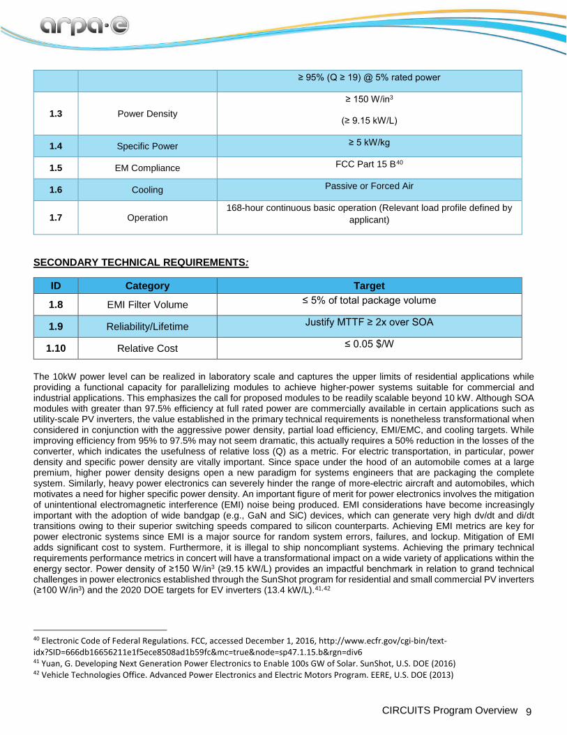
The 10kW power level can be realized in laboratory scale and captures the upper limits of residential applications while providing a functional capacity for parallelizing modules to achieve higher-power systems suitable for commercial and industrial applications. This emphasizes the call for proposed modules to be readily scalable beyond 10 kW. Although SOA modules with greater than 97.5% efficiency at full rated power are commercially available in certain applications such as utility-scale PV inverters, the value established in the primary technical requirements is nonetheless transformational when considered in conjunction with the aggressive power density, partial load efficiency, EMI/EMC, and cooling targets. While improving efficiency from 95% to 97.5% may not seem dramatic, this actually requires a 50% reduction in the losses of the converter, which indicates the usefulness of relative loss (Q) as a metric. For electric transportation, in particular, power density and specific power density are vitally important. Since space under the hood of an automobile comes at a large premium, higher power density designs open a new paradigm for systems engineers that are packaging the complete system. Similarly, heavy power electronics can severely hinder the range of more-electric aircraft and automobiles, which motivates a need for higher specific power density. An important figure of merit for power electronics involves the mitigation of unintentional electromagnetic interference (EMI) noise being produced. EMI considerations have become increasingly important with the adoption of wide bandgap (e.g., GaN and SiC) devices, which can generate very high dv/dt and di/dt transitions owing to their superior switching speeds compared to silicon counterparts. Achieving EMI metrics are key for power electronic systems since EMI is a major source for random system errors, failures, and lockup. Mitigation of EMI adds significant cost to system. Furthermore, it is illegal to ship noncompliant systems. Achieving the primary technical requirements performance metrics in concert will have a transformational impact on a wide variety of applications within the energy sector. Power density of ≥150 W/in3 (≥9.15 kW/L) provides an impactful benchmark in relation to grand technical challenges in power electronics established through the SunShot program for residential and small commercial PV inverters (≥100 W/in3) and the 2020 DOE targets for EV inverters (13.4 kW/L).41,42
40 Electronic Code of Federal Regulations. FCC, accessed December 1, 2016, http://www.ecfr.gov/cgi-bin/text-idx?SID=666db16656211e1f5ece8508ad1b59fc&mc=true&node=sp47.1.15.b&rgn=div6 41 Yuan, G. Developing Next Generation Power Electronics to Enable 100s GW of Solar. SunShot, U.S. DOE (2016) 42 Vehicle Technologies Office. Advanced Power Electronics and Electric Motors Program. EERE, U.S. DOE (2013)
10 CIRCUITS Program Overview
Partial load performance is a critical parameter that seeks to fully utilize the capability of WBG power semiconductors to operate efficiently at light-load conditions. The efficiency of many commercially available power converters decreases sharply below 10% rated power, which has significant energy impact in applications where partial load conditions constitute a substantial portion of operating time, such as VFDs, EV inverters, and PV power electronics in regions with low insolation.43,44 The additional requirement for utilization of passive or forced air cooling will push innovations in thermal management and packaging that can reduce system-level weight, complexity, and cost in transportation and stationary applications relative to water cooled systems. As for EMI considerations, instead of having to develop large, complex filtering strategies, truly disruptive solutions will minimize or not generate this noise. Filters to attenuate conducted EMI are another important obstacle to power density in all power electronics systems. EMI filters can comprise 15-40% of the inverter’s volume. Reduction in filter volume and weight while passing FCC Part 15 B EMI standards constitutes another significant challenge that can potentially be achieved by employing advanced topologies for power electronics systems. Novel topologies with inherently lower EMI will be accepted more readily by industry since this solves an important obstacle that often plagues systems-level integration and can be a bottleneck in successful prototype design. Applicants in Category 1 must propose at least one potential application area for their converter design. Applicants are also required to convincingly justify why their solution has a pathway to broad impact in at least one ARPA-E mission area, see Section I.A of the FOA. In all Full Applications, a detailed test plan for converter performance and reliability should be provided.
Category 2: Application-Specific Converter Systems In Category 2 this program seeks to fund specific grand technical challenges in application areas covering a broad range of power electronics disciplines, including, but not limited to: electric motor driven systems, automotive (electric and hybrid electric vehicles), electric vehicle chargers, high-performance computing and data centers, power supplies, solar inverters, wind-electric systems, solid-state lighting solutions, high/medium voltage transmission/distribution, grid applications, power conversion for grid storage, rail/ship propulsion, more-electric aerospace, monolithic power processing, robotic actuators, turbo-lifts, solid-state circuit breakers, power electronics interacting with the grid, variable frequency drives, power electronics for telecommunication gear, and emerging new applications not yet categorized. Effective power converter design requires careful analysis of the fundamental tradeoffs between system-level parameters such as safety, power density, efficiency, reliability, and cost. The relative importance of each of these characteristics depends heavily on the specific application. Figure 2 provides a qualitative example of the compromise between efficiency and power density. Each contour represents the Pareto optimum at a certain maximum operating temperature, where T1 < T2 < T3. Because the reliability of the system is in large part a function of temperature, the Mean Time To Failure (MTTF) generally follows the relationship MTTF1 > MTTF2 > MTTF3. Applications in which efficiency and reliability are more pertinent than power density (e.g., utility-scale PV inverters) favor the hypothetical converter performance indicated by the square symbol in Figure 2. Alternatively, applications such as automotive PCUs and onboard battery chargers that value high power densities to enable vehicle-level efficiency gains and simplification of cooling systems would benefit most from the performance metrics associated with the circular symbol, assuming reliability can meet or exceed industry standards. Beyond efficiency and power density, a variety of Pareto curves can be generated using combinations of the various system parameters. The overall performance metrics can thus be selected through a multi-objective optimization process, where circuit topologies have been shown to play an important role in defining the system performance limits.45
43 Anwar, M. et al. Power Dense and Robust Traction Power Inverter for the Second Generation Chevrolet Volt Extended-Range EV. SAE Int. J. Alt. Power (2015) 44 Chen, H. et al. Electrified Automotive Powertrain Architecture Using Composite DC–DC Converters. IEEE Transactions on Power Electronics (2017) 45 Burkart, R.; Kolar J. W. Component Cost Models for Multi-Objective Optimizations of Switched- Mode Power Converters. IEEE Energy Conversion Congress and Exposition (2013)

11 CIRCUITS Program Overview
Figure 2. Qualitative illustration of the efficiency-power density Pareto fronts associated with power converter operation. The symbols represent the hypothetical performance characteristics of two distinct converters. T = temperature; MTTF =
mean time to failure.
To accommodate a diverse pool of power electronics applications that have distinct performance and optimization criteria, applicants in Category 2 are responsible for defining and justifying the relevant metrics for their given use case. Applicants must also clearly define the performance of the current commercial SOA technology in their chosen application area and present quantitative grand technical challenges targets for their proposed solution with respect to the current SOA using a consistent set of criteria. More details are provided in the table below. Submissions should include discussion of the reciprocity between the specified performance characteristics using a similar framework as the one outlined in the previous paragraph and in Figure 2. Applicants should consider the barriers to commercial adoption in light of these performance tradeoffs (e.g., cost-efficiency, power density-reliability, etc.), with the expectation that early-stage projects will prioritize these tradeoffs differently than projects seeking to be positioned closer to commercialization at the end of the period of performance. Projected impact in at least one of the ARPA-E mission areas must be quantified and well justified. Whether a concept is transformational or incremental will be judged based on the metrics proposed, energy impact of the solution, and whether the solution has a chance of early adoption. Test protocols and procedures for benchmarking the performance of the proposed technology must be described in detail and should be consistent with best practices in the relevant application area. The following table demonstrates the suggested presentation of technical categories and metrics for applications in Category 2. Applicants should include SOA values and values for the proposed solution for each of the metrics. This table is not meant to be exhaustive, and additional metrics may be added to better contrast the proposed work with the application-specific SOA. Likewise, if a particular category or target in the following table is not relevant for the proposed technology, applicants should justify why it need not be included as a performance criterion.
ID Category Target
2.1 Application area --
2.2 Power module level
Converter/system function [AC/DC, DC/AC, DC/DC, universal Power (W) [specify time interval]
Voltage (V) Efficiency (%) and Q (Pout/Ploss) [peak, rated power, 5% full load, standard
weighted]

12 CIRCUITS Program Overview
Power density (W/in3 or kW/L); Specific power (kW/kg) Relative cost ($/kW)
Approximate MTTF (h) Cooling methodology
Number of discrete power modules
2.3 Circuit level
Topology/architecture Switching methodology
Switching frequency (kHz) Number of discrete drivers
EMI filter volume
2.4 Component level
Transistor type(s) and count Transistor specifications Diode type(s) and count
Diode specifications Diode count
Total semiconductor area (mm2) Module packaging
Inductor type(s) and count Total inductor volume (mm3) Capacitor type(s) and count
Total capacitor volume (mm3) 2.5 Benchmarking Define test protocols and procedures for quantifying converter performance