creating qsys components, quartus ii 12.0 handbook,...
TRANSCRIPT

QII51022-12.1.0
© 2012 Altera Corporation. All rights reserved. ALTERA, ARRIare trademarks of Altera Corporation and registered in the U.Strademarks or service marks are the property of their respectivsemiconductor products to current specifications in accordanceservices at any time without notice. Altera assumes no responsdescribed herein except as expressly agreed to in writing by Alon any published information and before placing orders for pr
Quartus II Handbook Version 12.1Volume 1: Design and SynthesisNovember 2012
November 2012QII51022-12.1.0
7. Creating Qsys Components
This chapter describes the structure of Qsys components, with an emphasis on using the Qsys Component Editor to create the Hardware Component Description File (_hw.tcl), which describes a Qsys component.
f For information about using advanced_hw.tcl features outside the Component Editor, refer to the Component Interface Tcl Reference chapter in volume 1 of the Quartus II Handbook.
f Qsys supports standard Avalon®, AMBA® AXI3™ (version 1.0), and AMBA AXI4™ (version 2.0) interfaces. For more information about Avalon and AXI interfaces, refer to the Avalon Interface Specifications and the AMBA Protocol Specifications on the ARM® website. AXI4-Lite is not supported for the Quartus II software, version 12.1.
Qsys ComponentsA Qsys component includes the following elements:
■ Information about the component type, such as name, version, and author.
■ HDL description of the component’s hardware.
■ Description of the component interface hardware, such as the types of I/O signals.
■ Description of the parameters that configure the operation of the component.
■ A parameter editor for configuring an instance of the component in Qsys.
Altera® provides components automatically installed with the Quartus® II software. You can obtain a list of Qsys-compliant components provided by third-party IP developers on the Intellectual Property & Reference Designs web page by typing Qsys Certified in the Search box, and then selecting IP Core & Reference Designs. Components are also provided with Altera development kits, which are listed on the All Development Kits web page.
Component InterfacesYou can design a component with as many interfaces and with any combination of the interface types as the component requires. For example, a component might provide an Avalon-ST source port for high-throughput data, in addition to a memory-mapped slave port for control.
A, CYCLONE, HARDCOPY, MAX, MEGACORE, NIOS, QUARTUS and STRATIX words and logos . Patent and Trademark Office and in other countries. All other words and logos identified as e holders as described at www.altera.com/common/legal.html. Altera warrants performance of its with Altera's standard warranty, but reserves the right to make changes to any products and ibility or liability arising out of the application or use of any information, product, or service tera. Altera customers are advised to obtain the latest version of device specifications before relying oducts or services.
ISO 9001:2008 Registered
Feedback SubscribeTwitter

7–2 Chapter 7: Creating Qsys ComponentsQsys Components
The following interfaces are available in Qsys:
■ Memory-Mapped—For Avalon-MM or AXI masters and slaves that communicate using memory-mapped read and write commands.
■ Avalon Streaming (Avalon-ST)—For point-to-point connections between Avalon-ST sources and sinks that stream data.
■ Interrupts—For point-to-point connections between interrupt senders that generate interrupts, and interrupt receivers that service interrupts.
■ Clocks—For point-to-point connections between clock sources and clock sinks.
■ Resets—For point-to-point connections between reset sources and reset sinks.
■ Avalon Tri-State Conduit (Avalon-TC)—For a tri-state conduit controller in the Qsys system connected to tri-state devices on the PCB.
■ Conduits—For point-to-point connections between conduit interfaces. You can use the conduit interface type to define a custom collection of signals that do not fit into any other interface category.
Component StructureYou define a component with a <component_name>_hw.tcl file, a text file written in the Tcl scripting language that describes the component to Qsys. You can create the _hw.tcl file manually, or by using the Component Editor.
The _hw.tcl file contains information about the name and location of the component design files, including SystemVerilog, Verilog HDL, or VHDL files, and constraint files that define the component for synthesis and simulation.
The Component Editor simplifies the process of creating _hw.tcl files by creating a file that you can use outside of the Component Editor to add advanced procedures. When you edit a previously saved _hw.tcl file, Qsys automatically backs up the earlier version as _hw.tcl~.
HDL Component TypesThe following sections describe Qsys component types based on how the design files are specified.
Static Components
You implement a static component using the same HDL files for all instances of the component. If the top-level HDL module is parameterized, instances may have unique behavior, depending on the parameter values.
Generated Components
A generated component's fileset callback allows an instance of the component to create unique HDL design files based on the instance's parameter values.
For example, you can write a fileset callback to include a control and status interface based on the value of a parameter. The callback overcomes a limitation of HDL languages, which do not allow runtime parameters.
Quartus II Handbook Version 12.1 November 2012 Altera CorporationVolume 1: Design and Synthesis

Chapter 7: Creating Qsys Components 7–3Qsys Components
Composed Components
Composed components are subsystems constructed from instances of other components. You can use a composition callback to manage the subsystem in a composed component.
f For information about defining a fileset or composition callback procedure, refer to the Component Interface Tcl Reference chapter in volume 1 of the Quartus II Handbook.
Component File OrganizationA typical component uses the following directory structure. The names of the directories are not significant.
■ <component_directory>/
■ <hdl>/—Contains the component HDL design files, for example .v or .vhd files that contain the top-level module.
■ <component_name>_hw.tcl—The component description file.
■ <component_name>_sw.tcl—The software driver configuration file. This file specifies the paths for the .c and .h files associated with the component, when required.
■ <software>/—Contains software drivers or libraries related to the component. Altera recommends that the software directory be a subdirectory of the directory that contains the _hw.tcl file.
f For information about writing a device driver or software package suitable for use with the Nios II processor, refer to the Hardware Abstraction Layer section of the Nios II Software Developer’s Handbook. The Nios II Software Build Tool Reference chapter of the Nios II Software Developer’s Handbook describes the commands you can use in the Tcl script.
Component VersionsYou can create and maintain multiple versions of the same component.
If you have multiple _hw.tcl files for components with the same NAME module properties and different VERSION module properties, both versions of the component are available.
If multiple versions of the component are available in the Qsys Component Library, you can add a specific version of a component by right-clicking the component, and then selecting Add version <version_number>. When multiple versions of a component are available, instances in the Qsys system must be of the same version.
November 2012 Altera Corporation Quartus II Handbook Version 12.1Volume 1: Design and Synthesis

7–4 Chapter 7: Creating Qsys ComponentsUsing the Qsys Component Editor
Using the Qsys Component EditorThe Qsys Component Editor allows you to create and package a component for use in Qsys. The Component Editor allows you to perform the following tasks:
■ Specify component’s identifying information, such as name, version, author, etc.
■ Specify the SystemVerilog, Verilog HDL, or VHDL files, and constraint files that define the component for synthesis and simulation.
■ Create an HDL template for a component by first defining its parameters, signals, and interfaces.
■ Associate and define signals for a component’s interfaces.
■ Set parameters on interfaces, which specify characteristics.
■ Specify relationships between interfaces.
■ Declare parameters that alter the component structure or functionality.
1 If the component is HDL-based, you must define the parameters and signals in the HDL file, and cannot add or remove them in the Component Editor. If you have not yet created the top-level HDL file, you declare the parameters and signals in the Component Editor, and they are then included in the HDL template file that Qsys creates.
For a description of the available interface types, refer to “Component Interfaces” on page 7–1. In a Qsys system, the interfaces of a component are connected within the system, or exported as top-level signals from the system.
If you are creating the component using an existing HDL file, the order in which the tabs appear in the Component Editor reflects the recommended design flow for component development. You can use the Prev and Next buttons at the bottom of the Component Editor window to guide you through the tabs.
If the component is not based on an existing HDL file, enter the parameters, signals, and interfaces first, and then return to the Files tab to create the top-level HDL file template. When you click Finish, Qsys creates the component _hw.tcl file with the details provided on the Component Editor tabs.
After the component is saved, it is available in the Qsys Component Library.
1 If you require features in the component that are not supported by the Component Editor, such as callback procedures, you can use the Component Editor to create the _hw.tcl file, and then manually edit the file to complete the component definition with commands in the Component Interface Tcl Reference chapter in volume 1 of the Quartus II Handbook.
h For more information about the procedures for creating components in the Component Editor, refer to Creating Qsys Components in Quartus II Help.
Opening the Qsys Component EditorYou open the Qsys Component Editor by clicking New Component under Project in the Component Library. Clicking the About triangle at the top-left of each tab in the Component Editor describes what information is required and displayed for that tab.
Quartus II Handbook Version 12.1 November 2012 Altera CorporationVolume 1: Design and Synthesis

Chapter 7: Creating Qsys Components 7–5Using the Qsys Component Editor
f This chapter uses the Demo AXI Memory example available on the Qsys Design Examples page of Altera's web site.
Component Type TabThe Component Type tab allows you to specify the following information about the component:
■ Name—Specifies the name used in the _hw.tcl filename, as well as in the top-level module name when you create a synthesis wrapper file for a non HDL-based component.
■ Display name—Identifies the component in the parameter editor GUI, and also appears in the Component Library under Project and on the System Contents tab.
■ Version—Specifies the version number of the component.
■ Group—Represents the category of the component in the list of available components in the Component Library. You can select an existing group from the list, or define a new group by typing a name in the Group box. Separating entries in the Group box with a slash defines a subcategory. For example, if you type Memories and Memory Controllers/On-Chip, the component appears in the Component Library under the On-Chip group, which is a subcategory of the Memories and Memory Controllers group. If you save the Qsys design in the project directory, the component appears in the Component Library in the group you specified under Project. Alternatively, if you save the design in the Quartus II installation directory, the component appears in the specified group under Library.
■ Description—Allows you to describe the component.
■ Created By—Allows you to specify the author of the component.
■ Icon—Allows you to enter the relative path to an icon file (.gif, .jpg, or .pgn format) that represents the component and appears as the header in the parameter editor for the component. The default image is the Altera MegaCore function icon.
■ Documentation—Allows you to add links to documentation for the component, and appears when you right-click the component in the Component Library, and then select Details.
■ To specify an Internet file, begin your path with http://, for example: http://mydomain.com/datasheets/my_memory_controller.html.
■ To specify a file in the file system, begin your path with file:/// for Linux, and file://// for Windows; for example (Windows): file:////company_server/datasheets/ my_memory_controller.pdf.
1 The Display name, Group, Description, Created By, Icon, and Documentation entries are optional.
November 2012 Altera Corporation Quartus II Handbook Version 12.1Volume 1: Design and Synthesis

7–6 Chapter 7: Creating Qsys ComponentsUsing the Qsys Component Editor
Figure 7–1 shows an example of the Component Type tab with the component information.
Example 7–1 shows the component hardware Tcl code related to the entries for the Component Type tab in Figure 7–1. This example also includes the required Tcl package require command, which specifies the ACDS version that Qsys uses to create the _hw.tcl file, and ensures compatibility with this version of the Qsys API in future ACDS releases.
Files TabThe Files tab allows you to specify files for synthesis and simulation. If you already have HDL code that describes the Qsys component that you want to create, you can specify the files on the Files tab, as described in “Specifying HDL Files for Synthesis” on page 7–7.
If you have not yet created the HDL code that describes the component, but you have identified the signals and parameters that you want in the component, you can use the Files tab to create a top-level HDL template file, as described in “Creating a New HDL File for Synthesis” on page 7–7.
Figure 7–1. Component Type Tab in the Component Editor
Example 7–1. Hardware Tcl Commands Created from the Component Type Tab
# # request TCL package from ACDS 12.1# package require -exact qsys 12.1# # module demo_axi_memory# set_module_property DESCRIPTION "Demo AXI-3 memory with optional Avalon-ST port"set_module_property NAME demo_axi_memoryset_module_property VERSION 1.0set_module_property GROUP "My Components"set_module_property AUTHOR Alteraset_module_property DISPLAY_NAME "Demo AXI Memory"
Quartus II Handbook Version 12.1 November 2012 Altera CorporationVolume 1: Design and Synthesis

Chapter 7: Creating Qsys Components 7–7Using the Qsys Component Editor
h For step-by-step instructions and more information about the Component Editor flow, refer to Creating Qsys Components in Quartus II Help.
Specifying HDL Files for SynthesisYou can add HDL files and other support files that should be included when this component is created to the list of Synthesis Files by clicking +, and then selecting the files in the Open dialog box.
1 A component must specify an HDL file as the top-level file, which contains the top-level module. The Synthesis Files list might also include supporting HDL files, such as timing constraints, or other files required to successfully synthesize and compile in the Quartus II software. The synthesis files for a component are copied to the generation output directory during Qsys system generation.
Figure 7–2 indicates the demo_axi_memory.sv file as the top-level file for the component in the Synthesis Files section on the Files tab.
Creating a New HDL File for Synthesis If you do not already have an HDL implementation of the component, you can use the Component Editor to define the component, and then create a simple top-level synthesis file containing the signals and parameters for the component. You can then edit this HDL file to add the logic that directs the component's behavior.
To begin, you first specify the information about the component on the Parameters, Signals, and Interfaces tabs, as described in the upcoming sections of this chapter. Then, you return to the Files tab to create an HDL file by clicking Create Synthesis File from Signals. The Component Editor creates an HDL file from the specified parameters and signals.
Figure 7–2. Using HDL Files to Define a Component
November 2012 Altera Corporation Quartus II Handbook Version 12.1Volume 1: Design and Synthesis

7–8 Chapter 7: Creating Qsys ComponentsUsing the Qsys Component Editor
Analyzing Synthesis FilesAfter the top-level HDL file is specified, click Analyze Synthesis Files to analyze the parameters and signals in the top-level, and then select the top-level module from the Top Level Module list. If there is a single module or entity in the HDL file, Qsys automatically populates the Top-level Module list.
Once analysis is complete and the top-level module is selected, the parameters and signals found in the top-level module are used as the parameters and signals for the component, and you can view them on the Parameters and Signals tabs. The Component Editor might report errors or warnings at this stage, because the signals and interfaces are not yet fully defined.
1 At this stage in the Component Editor flow, you cannot add or remove parameters or signals created from a specified HDL file without editing the HDL file itself.
Example 7–2 shows the component hardware Tcl code related to the entries for the Files Type tab in the Synthesis Files section in Figure 7–2.
The synthesis files are added to a fileset with the name QUARTUS_SYNTH and type QUARTUS_SYNTH. The top-level module is used to specify the TOP_LEVEL fileset property. Each synthesis file is individually added to the fileset. If the source files are saved in a different directory from the working directory where the _hw.tcl is located, you can use standard fixed or relative path notation to identify the file location for the PATH variable.
Naming HDL Signals for Automatic Interface and Type RecognitionIf you create the component's top-level HDL file before using the Component Editor, the Component Editor recognizes the interface and signal types based on the signal names in the source HDL file. This auto-recognition feature eliminates the task of manually assigning each interface and signal type in the Component Editor. To enable this auto-recognition feature, you must create signal names using the following naming convention:
<interface type prefix>_<interface name>_<signal type>
Specifying an interface name with <interface name> is optional if you have only one interface of each type in the component definition. For interfaces with only one signal, such as clock and reset inputs, the <interface type prefix> is also optional. When the Component Editor recognizes a valid prefix and signal type for a signal, it automatically assigns an interface and signal type to the signal based on the naming convention. If no interface name is specified for a signal, you can choose an interface name on the Interfaces tab in the Component Editor.
Example 7–2. Hardware Tcl Commands Created from the Files Tab - Synthesis FIles Section
## file sets#add_fileset QUARTUS_SYNTH QUARTUS_SYNTH "" ""set_fileset_property QUARTUS_SYNTH TOP_LEVEL demo_axi_memoryadd_fileset_file demo_axi_memory.sv SYSTEM_VERILOG PATH demo_axi_memory.svadd_fileset_file single_clk_ram.v VERILOG PATH single_clk_ram.v
Quartus II Handbook Version 12.1 November 2012 Altera CorporationVolume 1: Design and Synthesis

Chapter 7: Creating Qsys Components 7–9Using the Qsys Component Editor
1 Refer to the Avalon Interface Specifications or the AMBA AXI Protocol Specification for the signal types available for each interface type.
Example 7–3 shows a Verilog HDL module declaration with signal names that create clock, reset, AXI slave, and Avalon-ST source interfaces. The interface names are not specified because there is only one interface of each type.
Table 7–1 lists valid values for an <interface type prefix>.
Table 7–1. Interface Type Prefixes for Automatic Signal Recognition
Interface Prefix Interface Type
asi Avalon-ST sink (input)
aso Avalon-ST source (output)
avm Avalon-MM master
avs Avalon-MM slave
axm AXI master
axs AXI slave
coe Conduit
csi Clock Sink (input)
cso Clock Source (output)
inr Interrupt receiver
ins Interrupt sender
ncm Nios II custom instruction master
ncs Nios II custom instruction slave
rsi Reset sink (input)
rso Reset source (output)
tcm Avalon-TC master
tcs Avalon-TC slave
Example 7–3. Verilog HDL Module With Automatically Recognized Signal Names
module demo_axi_memory (
clk,reset_n,axs_awid,axs_awaddr,...avs_writedata,avs_readdata,...aso_data,aso_valid,aso_ready
);
November 2012 Altera Corporation Quartus II Handbook Version 12.1Volume 1: Design and Synthesis

7–10 Chapter 7: Creating Qsys ComponentsUsing the Qsys Component Editor
Specifying Files for SimulationTo support Qsys system generation for simulation, a component must specify the VHDL or Verilog simulation files. Simulation files are generated when a user adds the component to a Qsys system and chooses to generate Verilog or VHDL simulation files. In most cases, these files are the same as the synthesis files. If there are simulation-specific HDL files, you can use them in addition to, or in place of the synthesis files. To use your synthesis files as your simulation files, on the Files tab, click Copy From Synthesis Files to copy the list of synthesis files to the Verilog Simulation Files or VHDL Simulation Files lists.
You specify the simulation files in a similar way as the synthesis files with the fileset commands. Example 7–4 shows SIM_VERILOG and SIM_VHDL filesets for Verilog and VHDL simulation output files. In this example, the same Verilog files are used for both Verilog and VHDL outputs, and there is one additional System Verilog file added.
This method works for designers of Verilog IP to support users who want to generate a VHDL top-level simulation file when they have a mixed-language simulation tool and license that can read the Verilog output for the component.
Figure 7–3 shows the files specified for simulation on the Files tab.
Figure 7–3. Specifying the Simulation Output Files
Quartus II Handbook Version 12.1 November 2012 Altera CorporationVolume 1: Design and Synthesis

Chapter 7: Creating Qsys Components 7–11Using the Qsys Component Editor
Example 7–4 shows the component hardware Tcl code related to the entries for the Files Type tab in the Simulation Files section.
Parameters TabThe Parameters tab allows you specify the parameters that are used to configure instances of the component in a Qsys system.
The Parameters table displays the HDL parameters that are declared in the top-level HDL module. If you have not yet created the top-level HDL file, the parameters that you create on the Parameters tab are included in the top-level synthesis file template created from the Files tab.
When the component includes HDL files, the parameters match those defined in the top-level module, and you cannot be add or remove them on the Parameters tab. To add or remove the parameters, edit your HDL source, and then re-analyze the file.
If you used the Component Editor to create a top-level template HDL file for synthesis, you can remove the newly-created file from the Synthesis Files list on the Files tab, make your parameter changes, and then re-analyze the top-level synthesis file.
You can use the Parameters table to specify the following information about each parameter:
■ Name—Allows you to name the parameter.
■ Default Value—Sets the default value used in new instances of the component.
■ Editable—Specifies whether or not the user can edit the parameter value.
■ Type—Defines the parameter type as string, integer, boolean, std_logic, logic vector, natural, or positive.
■ Group—Allows you to group parameters in parameter editor.
■ Tooltip—Allows you to add a description of the parameter that appears when the user of the component points to the parameter in the parameter editor.
Example 7–4. Hardware Tcl Commands Created from the Files Tab - Simulation Files Section
add_fileset SIM_VERILOG SIM_VERILOG "" ""set_fileset_property SIM_VERILOG TOP_LEVEL demo_axi_memoryadd_fileset_file single_clk_ram.v VERILOG PATH single_clk_ram.vadd_fileset_file verbosity_pkg.sv SYSTEM_VERILOG PATH verification_lib/verbosity_pkg.svadd_fileset_file demo_axi_memory.sv SYSTEM_VERILOG PATH demo_axi_memory.svadd_fileset SIM_VHDL SIM_VHDL "" ""set_fileset_property SIM_VHDL TOP_LEVEL demo_axi_memoryset_fileset_property SIM_VHDL ENABLE_RELATIVE_INCLUDE_PATHS falseadd_fileset_file demo_axi_memory.sv SYSTEM_VERILOG PATH demo_axi_memory.svadd_fileset_file single_clk_ram.v VERILOG PATH single_clk_ram.vadd_fileset_file verbosity_pkg.sv SYSTEM_VERILOG PATH verification_lib/verbosity_pkg.sv
November 2012 Altera Corporation Quartus II Handbook Version 12.1Volume 1: Design and Synthesis

7–12 Chapter 7: Creating Qsys ComponentsUsing the Qsys Component Editor
You can click Preview the GUI at any time to see how the declared parameters appear in the parameter editor. Figure 7–4 shows parameters with their default values defined, with checks in the Editable column indicating that users of this component are allowed to modify the parameter value. You use the Group column to organize your parameters into sections in the parameter editor.
The following rules apply to HDL parameters in the parameter editor:
■ Editable parameters cannot contain computed expressions.
■ If a parameter <n> defines the width of a signal, the signal width must follow the format: <n-1>:0.
f Refer to Component Interface Tcl Reference chapter in volume 1 of the Quartus II Handbook for detailed information about creating and displaying parameters using Tcl scripts.
Example 7–5 shows the component hardware Tcl code related to the entries for the Parameters tab in Figure 7–4.
Figure 7–4. Parameters Tab in the Components Editor
Quartus II Handbook Version 12.1 November 2012 Altera CorporationVolume 1: Design and Synthesis

Chapter 7: Creating Qsys Components 7–13Using the Qsys Component Editor
In this example, the first add_parameter command includes commonly-specified properties. The set_parameter_property command specifies each property individually. The Tooltip column on the Parameters tab maps to the DESCRIPTION property, and there is an additional unused UNITS property created in the code. The HDL_PARAMETER property specifies that the value of the parameter is specified in the HDL instance wrapper when creating instances of the component. The Group column in the Parameters tab maps to the display items section with the add_display_item commands.
Signals TabThe Signals tab allows you to specify the interface and signal type of each signal in the component. When you add HDL files to the Synthesis Files table on the Files tab, and then click Analyze Synthesis Files, the signals on the top-level module appear on the Signals tab.
If you have not yet created your top-level HDL file, you can click Add Signal to specify each top-level signal in the component. For each signal that you add, you must provide the appropriate values in the Name, Interface, Signal Type, Width, and Direction columns. You can use the error and warning messages at the bottom of the window to guide your selections. You can edit the signal name by double-clicking the Name column, and then typing the new name.
After you have analyzed the component's top-level HDL file on the Files tab, you cannot add or remove signals or change the signal names on the Signals tab. To change the signals, edit your HDL source, and then re-analyze the file.
If you used the Component Editor to create a top-level template HDL file for synthesis, you can remove the newly-created file from the Synthesis Files list on the Files tab, make your signal changes, and then re-analyze the top-level synthesis file.
Example 7–5. Hardware Tcl Commands Created from the Parameters Tab
# # parameters# add_parameter AXI_ID_W INTEGER 4 "Width of ID fields"set_parameter_property AXI_ID_W DEFAULT_VALUE 4set_parameter_property AXI_ID_W DISPLAY_NAME AXI_ID_Wset_parameter_property AXI_ID_W TYPE INTEGERset_parameter_property AXI_ID_W UNITS Noneset_parameter_property AXI_ID_W DESCRIPTION "Width of ID fields"set_parameter_property AXI_ID_W HDL_PARAMETER trueadd_parameter AXI_ADDRESS_W INTEGER 12set_parameter_property AXI_ADDRESS_W DEFAULT_VALUE 12
add_parameter AXI_DATA_W INTEGER 32...# # display items# add_display_item "AXI Port Widths" AXI_ID_W PARAMETER ""
November 2012 Altera Corporation Quartus II Handbook Version 12.1Volume 1: Design and Synthesis

7–14 Chapter 7: Creating Qsys ComponentsUsing the Qsys Component Editor
The Interface column allows you assign a signal to an interface. Each signal must belong to an interface and be assigned a legal signal type for that interface. To create a new interface of a specific type, select new <interface type> from the list; this new interface then become available in the list for subsequent signal assignments. You can highlight all of the signals in an interface and then select an Interface from the list to apply the Interface name to each signal in the interface.
You edit the interface name on the Interface tab; you cannot edit the interface name on the Signals tab.
Figure 7–5 shows the altera_axi_slave selection available for the axs_awaddr signal.
Interfaces TabThe Interfaces tab allows you to manage settings for each interface of the component. The interface name appears on the Signals tab, and in the Qsys System Contents tab when the component is added to a system.
You can configure the type and properties of each interface. Some interfaces display waveforms that illustrate the timing for the interface. If you update timing parameters, the waveforms automatically update.
You add additional interfaces by clicking Add Interface, and then you must specify the signals for the added interface on the Signals tab. You can remove interfaces without signals by clicking Remove Interfaces With No Signals.
Figure 7–5. Signals Tab in the Components Editor
Quartus II Handbook Version 12.1 November 2012 Altera CorporationVolume 1: Design and Synthesis

Chapter 7: Creating Qsys Components 7–15Using the Qsys Component Editor
Figure 7–6 shows the Avalon Streaming Source interface, named streaming.
Figure 7–6. Interfaces Tab in the Components Editor
November 2012 Altera Corporation Quartus II Handbook Version 12.1Volume 1: Design and Synthesis
7–16 Chapter 7: Creating Qsys ComponentsUsing the Qsys Component Editor
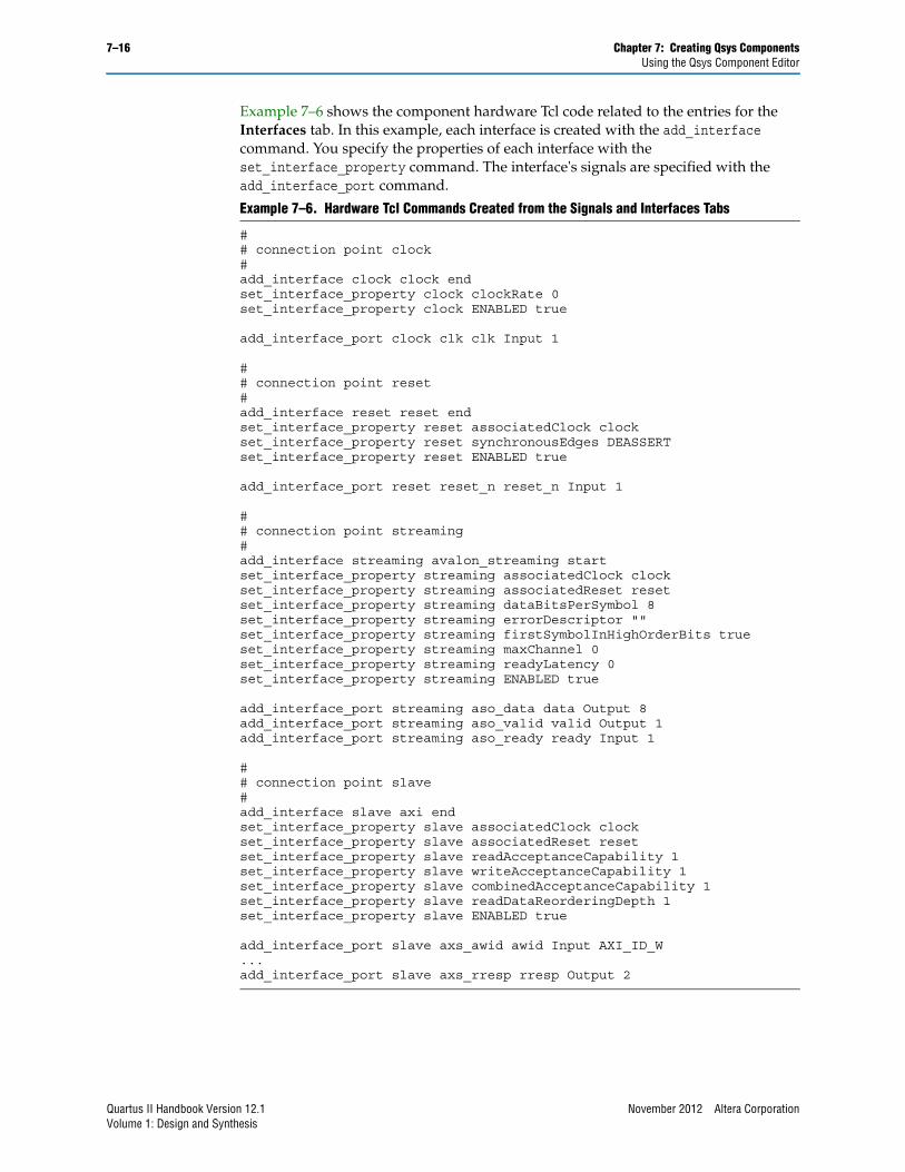
Example 7–6 shows the component hardware Tcl code related to the entries for the Interfaces tab. In this example, each interface is created with the add_interface command. You specify the properties of each interface with the set_interface_property command. The interface's signals are specified with the add_interface_port command.
Example 7–6. Hardware Tcl Commands Created from the Signals and Interfaces Tabs
# # connection point clock# add_interface clock clock endset_interface_property clock clockRate 0set_interface_property clock ENABLED true
add_interface_port clock clk clk Input 1
# # connection point reset# add_interface reset reset endset_interface_property reset associatedClock clockset_interface_property reset synchronousEdges DEASSERTset_interface_property reset ENABLED true
add_interface_port reset reset_n reset_n Input 1
# # connection point streaming# add_interface streaming avalon_streaming startset_interface_property streaming associatedClock clockset_interface_property streaming associatedReset resetset_interface_property streaming dataBitsPerSymbol 8set_interface_property streaming errorDescriptor ""set_interface_property streaming firstSymbolInHighOrderBits trueset_interface_property streaming maxChannel 0set_interface_property streaming readyLatency 0set_interface_property streaming ENABLED true
add_interface_port streaming aso_data data Output 8add_interface_port streaming aso_valid valid Output 1add_interface_port streaming aso_ready ready Input 1
# # connection point slave# add_interface slave axi endset_interface_property slave associatedClock clockset_interface_property slave associatedReset resetset_interface_property slave readAcceptanceCapability 1set_interface_property slave writeAcceptanceCapability 1set_interface_property slave combinedAcceptanceCapability 1set_interface_property slave readDataReorderingDepth 1set_interface_property slave ENABLED true
add_interface_port slave axs_awid awid Input AXI_ID_W...add_interface_port slave axs_rresp rresp Output 2
Quartus II Handbook Version 12.1 November 2012 Altera CorporationVolume 1: Design and Synthesis

Chapter 7: Creating Qsys Components 7–17Registering Software Assignments
Registering Software AssignmentsYou can use Tcl commands to create software assignments, and register any software assignment that you want, as arbitrary key-value pairs. Example 7–7 shows a typical Tcl API script:
The assignments are added to the .sopcinfo file, which is available for use for downstream tools.
f For more information about software assignments, refer to the Publishing Component Information to Embedded Software chapter in the Nios II Software Developer’s Handbook.
Saving a Component and Creating an _hw.tcl FileYou save a component by clicking Finish in the Component Editor. The Component Editor saves the component to a file with the file name <component_name>_hw.tcl.
You can move component files into a new directory, such as a network location, so that other users can use the component in their systems. The _hw.tcl file contains relative paths to the other files, so if you move an _hw.tcl file, you should also move all the HDL and other files associated with it.
1 Altera recommends that you save _hw.tcl files and their associated files in an ip/<class-name> directory within your Quartus II project directory.
Editing a ComponentIn Qsys, you make changes to a component by right-clicking the component in the Component Library, and then clicking Edit. After making changes, click Finish to save the changes to the _hw.tcl file. You can open the _hw.tcl file in a text editor to view the hardware Tcl for the component. If you edit the _hw.tcl file to use advanced features, you cannot use the Component Editor to make further changes without over-writing the original file.
1 You cannot use the Component Editor to edit components installed with the Quartus II software, such as Altera-provided components.
If you edit the HDL for a component and change the interface to the top-level module, you must edit the component to reflect the changes you made to the HDL.
f For more information about _hw.tcl syntax and advanced features that you can add to a component definition, refer to the Component Interface Tcl Reference chapter in volume 1 of the Quartus II Handbook.
Example 7–7. Typical Software Assignment with Tcl API Scripting
set_module_assignment name valueset_interface_assignment name value
November 2012 Altera Corporation Quartus II Handbook Version 12.1Volume 1: Design and Synthesis

7–18 Chapter 7: Creating Qsys ComponentsDocument Revision History
Document Revision HistoryTable 7–2 shows the revision history for this document.
f For previous versions of the Quartus II Handbook, refer to the Quartus II Handbook Archive.
Table 7–2. Document Revision History
Date Version Changes
November 2012 12.1.0■ Added AMBA AXI4 support.
■ Added the demo_axi_memory example with screen shots and example _hw.tcl code.
June 2012 12.0.0■ Added new tab structure for the Component Editor.
■ Added AMBA AXI3 support.
November 2011 11.1.0 Template update.
May 2011 11.0.0
■ Removed beta status.
■ Added Avalon Tri-state Conduit (Avalon-TC) interface type.
■ Added many interface templates for Nios custom instructions and Avalon-TC interfaces.
December 2010 10.1.0 Initial release.
Quartus II Handbook Version 12.1 November 2012 Altera CorporationVolume 1: Design and Synthesis