creating steel fabrication friendly families and...
TRANSCRIPT
Creating Steel Fabrication Friendly Families and Schedules with Autodesk® Revit® Structure Tina Bos – Herold Engineering Limited
SE3048-L Once you have mastered the day-to-day use of Autodesk Revit Structure, you must
continue to push the boundaries toward enhanced integration for construction purposes. One of the most commonly used materials in a structural engineer’s arsenal is structural steel. In this hands-on lab, we focus on using the information contained within Revit and the information we can derive from within custom family content to create enhanced structural steel schedules. This class is about the use of shared parameters and custom families to facilitate greater symmetry with steel fabricators through the use of smarter families and schedules.
Learning Objectives At the end of this class, you will be able to:
• Use shared parameters to make smarter families and schedules
• Create a parametric steel plate family and detailed geometrical schedule
• Use parameters and calculated values for steel quantity takeoffs
• Create a steel takeoff schedule
About the Speaker
Tina is a Senior Structural Technologist and the BIM Leader for Herold Engineering in Victoria,
BC. Tina is a lead Revit Structure modeler, producing construction documents in Revit since
2006. Tina creates and maintains all Revit standards and content as well as providing on-
going internal Revit training. She is responsible for the development of long term goals and
strategies for the structural discipline and the overall BIM planning for the company. Tina is
also chair of the BIMbc Victoria Revit Users Group.

Creating Steel Fabrication Friendly Families and Schedules with Autodesk® Revit® Structure
2
Section 1: Create a Steel Base Plate Family
In this section you will create a rectangular steel base plate family complete with shared
parameters.
1. Open Autodesk® Revit® 2014 and open the file SE3048-L Family Testing Project in the
session folder C:\DataSets\Tuesday\SE3048-L.
2. Start a new Structural Column Family using the default imperial family template.
TIP: Use the structural column family template instead of the generic model face based
template for your custom base plate family. This will allow easier placement of the base
plate to the column, priority graphical representation in the plans, and each base plate will
also appear and can be tagged within the graphical column schedule.
NOTE: If using the metric structural column family template, this template
includes Depth and Width parameters and related dimensions that need to be
deleted prior to beginning this exercise.

Creating Steel Fabrication Friendly Families and Schedules with Autodesk® Revit® Structure
3
3. Save the new family as BasePlate_4bolt.rfa to C:Datasets|Tuesday|SE3048-L
4. From the Manage Tab, select Shared Parameters
Load the file SE3048-L.txt in the session folder C:\DataSets\Tuesday\SE3048-L
5. In the Shared Parameters dialog box, create a new Group named S-Base Plate
6. The following parameters have been created within the group S-Base Plate:
*Note: Use your company abbreviation where hel* is indicated.
Name Discipline Type of Parameter
b_hel* Common Length
h_hel* Common Length
b_hole spacing Common Length
h_hole spacing Common Length
hole_diameter Common Length
plate_thickness Common Length
anchor_embed Common Length
anchor_count Common Text
anchor_type Common Text
plate_type Common Text
7. Select the Center (Left/Right) reference plane and check: Defines Origin. Then repeat
this for the Center (Front/ Back) reference plane.
TIP: Use a discipline prefix descriptor for parameter
groups within a multi-discipline shared parameter file.
Creating Steel Fabrication Friendly Families and Schedules with Autodesk® Revit® Structure
4
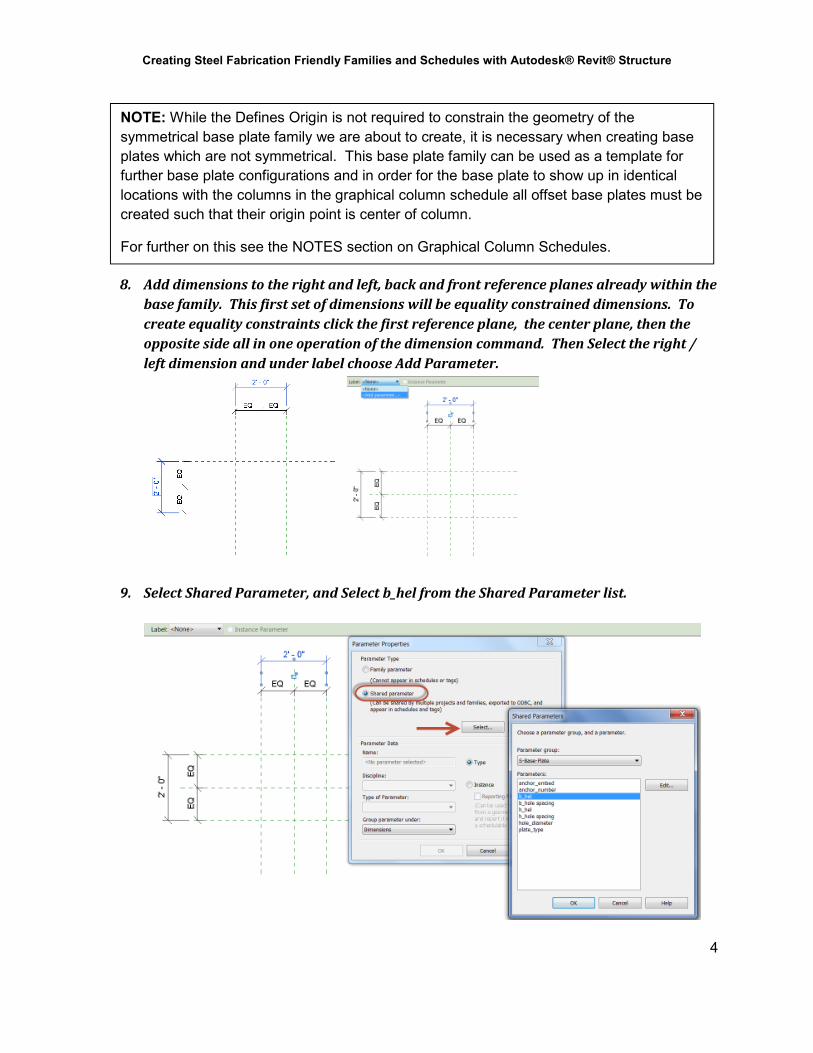
8. Add dimensions to the right and left, back and front reference planes already within the
base family. This first set of dimensions will be equality constrained dimensions. To
create equality constraints click the first reference plane, the center plane, then the
opposite side all in one operation of the dimension command. Then Select the right /
left dimension and under label choose Add Parameter.
9. Select Shared Parameter, and Select b_hel from the Shared Parameter list.
NOTE: While the Defines Origin is not required to constrain the geometry of the
symmetrical base plate family we are about to create, it is necessary when creating base
plates which are not symmetrical. This base plate family can be used as a template for
further base plate configurations and in order for the base plate to show up in identical
locations with the columns in the graphical column schedule all offset base plates must be
created such that their origin point is center of column.
For further on this see the NOTES section on Graphical Column Schedules.

Creating Steel Fabrication Friendly Families and Schedules with Autodesk® Revit® Structure
5
Within the Parameter Properties box you can now choose whether the parameter will
be a type or instance property, and where you’d like the parameter grouped.
The width parameter, b_hel will be a type parameter and located within the dimensions
grouping in Type Properties dialogue box.
10. Repeat Step 9 and add the length parameter, h_hel to the family.
11. Flex the family.
From the Properties Panel, select Family Types. In the family types dialogue box change
the h_hel and b_hel values and confirm that the reference planes move accordingly.

Creating Steel Fabrication Friendly Families and Schedules with Autodesk® Revit® Structure
6
12. Select the Create Tab, choose the Forms Panel - Extrusion
In sketch mode, draw a rectangle.
Align and lock the sides of the rectangle to the right, left, back and front reference
planes. Then select Finish Edit Mode.
13. Flex the family.
From the Properties Panel, select Family Types. In the family types dialogue box change
the h_hel and b_hel values and confirm that the extrusion moves accordingly.
14. Open the Front Elevation. Add a reference plane above and parallel to the Lower Ref
Level. Name the reference plane: Top of Base Plate. Add a dimension from the Lower
Ref Level to the Top of Base Plate reference plane. As per step 9, label and add the

Creating Steel Fabrication Friendly Families and Schedules with Autodesk® Revit® Structure
7
shared parameter plate_thickness as a type parameter grouped under dimensions to
this dimension.
15. Flex the family.
From the Properties Panel, select Family Types. In the family types dialogue box change
the plate_thickness value and confirm that the reference plane moves accordingly.
16. Align and lock the top of the extrusion to the Top of Base Plate reference plane.
17. Flex the family.
From the Properties Panel, select Family Types. In the family types dialogue box change
the plate_thickness value and confirm that the extrusion moves accordingly.
18. Create a Base Plate Type.
In the family type dialogue box create at least one default plate type. Additional types
will be created on a project by project basis.

Creating Steel Fabrication Friendly Families and Schedules with Autodesk® Revit® Structure
8
19. Test the family.
Load the Base Plate family into the SE3048-L Family Testing Project (this is the out of
the box Structural Analysis Template saved as a project) and check all the type
properties for the desired results.
Open the Level 1 plan view and place a base plate. Note that the Top Level and Offset
parameters are redundant because the extrusion is locked to the Top of Base Plate
reference plane and the plate_thickness parameter is used to control the extrusion for
each type. Elevation of the base plate is controlled by the Base Level and Base Offset
parameters.
Note: the alignment of the plate in elevation. The extrusion extends up from the Base
Level elevation. This is my preference and you can adjust the extrusion settings to suit
your work flow standards.
TIP: Test all your families and any downloaded content within a family testing
project created from your company template before loading it into any project.

Creating Steel Fabrication Friendly Families and Schedules with Autodesk® Revit® Structure
9
Section 2: Adding Bolt Holes to the Steel Base Plate Family
1. From the Create Tab, choose Datum Panel, select Reference Plane
• Add four references planes that will serve as bolt hole origin points.
• Add the b_hole spacing and h_hole spacing shared parameters. As before,
these will both be type parameters grouped under the Dimensions.
• Add two more aligned dimension strings with equality constraints to the
hole spacing dimensions about the centerline of the plate.
2. Flex the family.
From the Properties Panel, choose Family Types. In the family types dialogue box
change the h_hole spacing and b_hole spacing values and confirm that the reference
plane moves accordingly.
At this point you can continue to work with your Base Plate family or open the
dataset family: SE3048-L BasePlate 2.rfa

Creating Steel Fabrication Friendly Families and Schedules with Autodesk® Revit® Structure
10
3. From the Create Tab, choose the Forms Panel, select Void Forms, then Void
Extrusion
• Check the void extrusion setting on the option bar. In this case, change the
depth to 1” to match our current plate thickness.
• Add four 1” diameter circles at the intersection of the hole spacing reference
planes.
• Add a diameter dimension to each circle and constrain it with the
hole_diameter shared parameter.
• Finish Edit Mode.
•
4. Open the Front Elevation.
• Change the plate_thickness value to 3” for easier visibility.
• Align and lock the void extrusion to the Top of Base Plate Reference Plane
• Change the plate_thickness back to 1” confirming the void extrusion is
behaving properly.

Creating Steel Fabrication Friendly Families and Schedules with Autodesk® Revit® Structure
11
5. Flex the family.
From the Properties Panel, choose Family Types. In the family types dialogue box
change the h_hole spacing, b_hole spacing, and hole_diameter values and confirm that
the void move and change size accordingly.
Finishing Touches – Visibility, Material and Shared Parameters
1. Visibility:
• Select the Base Plate Extrusion and choose Visibility Settings
• The Base Plate is currently set to be visible in all views at all detail levels.
This is my preference. You can alter the visibility levels and add symbolic
lines to suit your company standards.
• Select the Manage Tab and choose Object Styles and create a new
Subcategory named Base Plate.
At this point you can continue to work with your Base Plate family or
open the dataset family: SE3048-L BasePlate 3.rfa

Creating Steel Fabrication Friendly Families and Schedules with Autodesk® Revit® Structure
12
• Select the Manage Tab and choose Object Styles and create a new
Subcategory named Base Plate. You can then set Object styles to control
visibility of the base plate within the family and with your projects.
• Once the Subcategory is created it must be assigned to the base plate. Select
the base plate and choose the Subcategory pull down. Set it to Base Plate.
2. Material: There are a half dozen default materials in the structural column family
template. Add a steel material to the Base Plate family.
• From the Manage Tab, select Transfer Project Standards
• Transfer Standards from the SE3048-L Family Testing Project
• Check none then Select only Materials to transfer into the Base Plate Family

Creating Steel Fabrication Friendly Families and Schedules with Autodesk® Revit® Structure
13
• Open the Family Types dialogue box
• Select Material and choose Steel ASTM A36 from the list of materials now
contained in the Material browser.
3. Shared Parameters: There are a few more shared utility type parameters to add to
the family for the purposes of the schedule we will build in the next section.
4. Open the Family Types dialogue box and add the following shared parameters as
Type parameters and Group under Structural.
anchor_embed
anchor_count
anchor_type
plate_type
TIP: Adding non-geometrical shared parameters to a family means these parameters
are specific to the base plate family. In this case, because we’ve used a structural
column as the family template, adding the shared parameters to the schedule within our
project would also assign them globally to all structural columns in a project.
NOTE: In this case these shared parameters are not dimensions and should therefore be
grouped in another category to suit your company standards. For consistency, I typically
choose to group all company custom parameters under Structural for the ease of the users.
NOTE: Ideally we would transfer project standards from the company
template to maintain consistent standards. In lieu of transferring project
standards for the material however, you can also create your own material by
duplicating and editing one from the family template.

Creating Steel Fabrication Friendly Families and Schedules with Autodesk® Revit® Structure
14
• Assign default text values to the newly added shared parameters. These
values will then remain constant until changed for each new type of base
plate created. If left blank, you would need to input these 3 values with each
new type created, using this method you need only edit the anchor_embed
parameter if necessary to change the default type.
Section 3: Create a Steel Base Plate Schedule
1. Open the project SE3048-L Base Plate Schedule Project.
2. From the View Tab, choose Schedules, and select Schedule/Quantities
• Select Structural Columns
• Name the schedule: Base Plate Schedule
3. The Schedule Properties Dialogue box will open to the Fields tab, add the following
parameters to the schedule:
• Type Mark
• b_hel
• h_hel
• plate_thickness
• b_hole spacing
• h-hole spacing
• hole diameter
• anchor_type
• anchor_embed
• anchor_count
• Type Comments
• Count
• Volume

Creating Steel Fabrication Friendly Families and Schedules with Autodesk® Revit® Structure
15
4. Add a Calculated Value named: volume_calc and add the following:
• Discipline: Common
• Type: Volume
• Formula: b_hel*h_hel*plate_thickness
5. Add a Calculated Value named: weight_calc
and add the following:
• Discipline: Structural
• Type: Mass
• Formula:
volume_calc*489.99168lbm/ft³
6. Add a Calculated Value named:
total_weight_calc and add the following:
• Discipline: Structural
• Type: Mass
• Formula: weight_calc
TIP: Select the pickbox to add
already scheduled parameters to the
Formula instead of typing them in.
NOTE: The out of the box Volume
parameter is a net volume value
(revit will deduct the voids from the
total plate volume). The
volume_calc we have just added is
a gross volume.

Creating Steel Fabrication Friendly Families and Schedules with Autodesk® Revit® Structure
16
7. Select the Filter Tab and set the first filter to:
• Type Mark
• contains
• BP
8. Select the Sorting/Grouping Tab and set the first sort filter to
• Type Mark
• Ascending
• Uncheck Itemize every Instance
• Check Grand totals and Select Totals only from the pull-down
9. Select the Formatting Tab, Select all Fields and set the alignment to Center
10. Select the weight_calc and check Calculate totals.
Note: You may wish to select “Count and
totals” which will give you a total count of the
base plates and their combined weights.
However the count total aligns to the far left of
the schedule far away from the count
parameter and seemingly unrelated to the
count parameter further along in the schedule.
Creating Steel Fabrication Friendly Families and Schedules with Autodesk® Revit® Structure
17
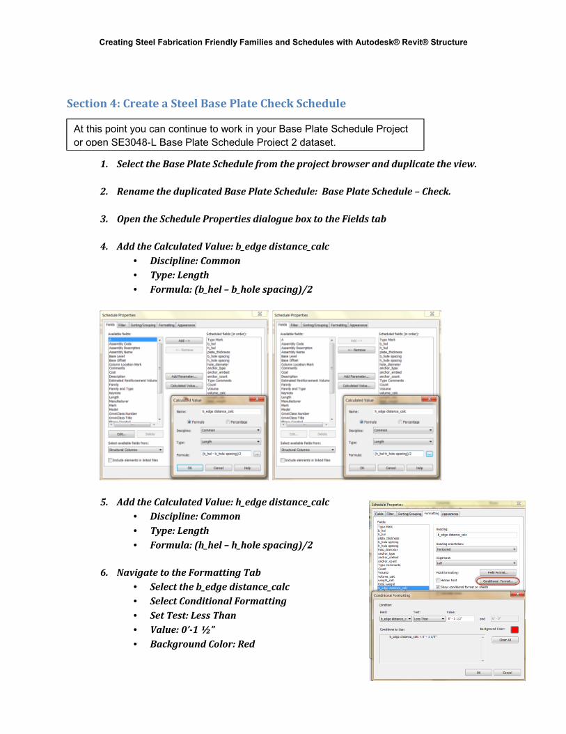
Section 4: Create a Steel Base Plate Check Schedule
1. Select the Base Plate Schedule from the project browser and duplicate the view.
2. Rename the duplicated Base Plate Schedule: Base Plate Schedule – Check.
3. Open the Schedule Properties dialogue box to the Fields tab
4. Add the Calculated Value: b_edge distance_calc
• Discipline: Common
• Type: Length
• Formula: (b_hel – b_hole spacing)/2
5. Add the Calculated Value: h_edge distance_calc
• Discipline: Common
• Type: Length
• Formula: (h_hel – h_hole spacing)/2
6. Navigate to the Formatting Tab
• Select the b_edge distance_calc
• Select Conditional Formatting
• Set Test: Less Than
• Value: 0’-1 ½”
• Background Color: Red
At this point you can continue to work in your Base Plate Schedule Project
or open SE3048-L Base Plate Schedule Project 2 dataset.

Creating Steel Fabrication Friendly Families and Schedules with Autodesk® Revit® Structure
18
7. Repeat the same steps for the h_edge distance_calc
8. Note that the BP2 has flagged an error for the b_hole distance_calc.
9. Return to the Base Plate Schedule and Cleanup / Format for Sheet Placement
• Schedule Properties box, Formatting, select the Volume and volume_calc
fields and make them Hidden
• Revise all the Column Title names
• Apply your company template to the schedule
Section 5: Create a Steel Beam Schedule
1. From the View Tab, choose Schedules, select Schedule/Quantities
• Select Structural Framing
• Name the schedule: STEEL BEAM TAKEOFF SCHEDULE
2. The Schedule Properties Dialogue box will open to the Fields tab, add the following
parameters to the schedule:
• Type
• Reference Level
• Count
• Length
• W
3. Add a Calculated Value named: weight_calc and
add the following:
• Discipline: Structural
• Type: Mass
• Formula: (W * 1 lb/ft) * Length
At this point you can continue to work in your Base Plate Schedule Project or open
SE3048-L Base Plate Schedule Project 3 dataset.
NOTE: The W parameter selected
above has an “other” designation
within the OOTB family. So we
assign units by multiplying by 1 lb/ft.

Creating Steel Fabrication Friendly Families and Schedules with Autodesk® Revit® Structure
19
4. Select the Sorting/Grouping tab:
• Sort by: Reference Level
o Check the Footer Checkbox
o Select: Title and totals
o Check the Blank Line Checkbox
• Then Sort by: Type
o Check the Grand totals Checkbox,
o Select: Totals only
o Uncheck the Itemize every instance
Checkbox
5. Select the Formatting tab:
• Select the field weight_calc and check Calculate totals checkbox
6. Cleanup the schedule for Sheet Placement
• Revise all the Column Title names
• Apply your company view template to the schedule

Creating Steel Fabrication Friendly Families and Schedules with Autodesk® Revit® Structure
20
Section 6: Tips and Tricks for the Graphical Steel Column Schedule
1. Tag Base Plates in the graphical column schedule.
Since the base plate family has been created using the column template family, base
plates are visible and can be tagged along with the columns in the graphical column
schedule.
2. Columns offset from gridlines.
The column location of columns that are offset yet still touching the gridline are
actually indicated as centered on the gridline in the graphical column schedule.
In the example below, the centerline of the column is actually 1 ½” away from grid
1, but the column location is noted as E-1.

Creating Steel Fabrication Friendly Families and Schedules with Autodesk® Revit® Structure
21
A little opaque text can remedy this issue, but remember to make a note of this
important overridden value in the project team notes in your revit project.
3. Base Plate Origins
As mentioned earlier, all base plate families should be created in consideration with
their origin being the centerline of column. This allows you to easily place and align
base plates with the centerline of columns. If you are creating an offset non-
symmetrical base plate identify the origins within the family and add parameters to
flex and offset types accordingly.
In the SE3048-L Base Plate Schedule Project I have added an offset base plate family
to highlight this point. In the clip below, the offset base plate origin has been
assigned and is aligned with the centerline of column as is confirmed by the
graphical column schedule.
However, should we move that base plate even slightly from centerline of column,
we can see that the graphical column schedule will now report the base plate and
column as two separate columns.

Creating Steel Fabrication Friendly Families and Schedules with Autodesk® Revit® Structure
22
4. Custom Base Plates and the Resultant Base Plate Schedule
Custom base plate orientations and bolting patterns will require additional
parameters in the families and in the base plate schedule or perhaps just additional
detailing. For our standards I have chosen to go with additional detailing and
added a comment section to the schedule to reference the details. This is one
method to achieve the same result without creating reams of additional base plate
family types. See the clips below.