cree xlamp xb-d led data sheet · temperature coefficient of voltage - royal blue mv/°c -2.0...
TRANSCRIPT

PRODUCT FAMILY DATA SHEET
Copyright © 2011-2019 Cree, Inc. All rights reserved. The information in this document is subject to change without notice. Cree®, the Cree logo and XLamp® are registered trademarks of Cree, Inc. UL® and the UR logo are registered trademarks of UL LLC.
Cree, Inc.4600 Silicon Drive
Durham, NC 27703USA Tel: +1.919.313.5300
WW
W.C
REE.
CO
M/X
LAM
PC
LD-D
S45 REV
12
Cree® XLamp® XB-D LEDs
PRODUCT DESCRIPTION
The XLamp® XB-D LED brings
next-generation performance, price and
size to all LED lighting applications. The
XB-D’s footprint enables smaller designs
with densely packed arrays for better
light mixing and concentration.
The XB-D shares common footprint and
uniform package design across all white
and color configurations, simplifying
board and optical designs for many
LED systems. The XB-D is optimized to
dramatically lower system cost in any
illumination application, from indoor
and outdoor lighting to architectural and
transportation lighting.
FEATURES
• XB-D white binned @ 85 °C; XB-D
color binned @ 25 °C
• Up to 136 lm/W in cool white
(@ 85 °C, 350 mA)
• Available in white, 80-minimum CRI
white, and 70-minimum CRI cool
white, royal blue, blue, green, PC
amber, amber, red-orange & red
• 1 A maximum drive current
• Wide viewing angle: from 110° (PC
amber) to 140° (red)
• Reflow solderable - JEDEC
J-STD-020C compatible
• Unlimited floor life at
≤ 30 °C/85% RH
• Electrically neutral thermal path
• RoHS and REACh compliant
• UL® recognized component
(E349212)
TABLE OF CONTENTS
Characteristics ....................................... 2
Flux Characteristics - White ................... 3
Flux Characteristics - Color ................... 4
Relative Spectral Power Distribution .... 6
Relative Flux vs. Junction
Temperature ........................................... 7
Electrical Characteristics ....................... 8
Electrical Characteristics ....................... 8
Relative Flux vs. Current ........................ 9
Relative Flux vs. Current ........................ 9
Relative Chromaticity vs. Current ........ 10
Relative Chromaticity vs.
Temperature ......................................... 11
Typical Spatial Distribution .................. 11
Thermal Design .................................... 12
Reflow Soldering Characteristics ........ 14
Notes .................................................... 15
Mechanical Dimensions ...................... 17
Tape and Reel ....................................... 19
Packaging ............................................. 20

Copyright © 2011-2019 Cree, Inc. All rights reserved. The information in this document is subject to change without notice. Cree®, the Cree logo and XLamp® are registered trademarks of Cree, Inc. UL® and the UR logo are registered trademarks of UL LLC.
2
XLAMP® XB-D LED
CHARACTERISTICS
Characteristics Unit Minimum Typical Maximum
Thermal resistance, junction to solder point - white, royal blue, blue °C/W 6.5
Thermal resistance, junction to solder point - green °C/W 11
Thermal resistance, junction to solder point - PC amber °C/W 8.5
Thermal resistance, junction to solder point - amber °C/W 7
Thermal resistance, junction to solder point - red-orange, red °C/W 5
Viewing angle (FWHM) - white degrees 115
Viewing angle (FWHM) - royal blue degrees 120
Viewing angle (FWHM) - blue, green degrees 135
Viewing angle (FWHM) - PC amber, degrees 110
Viewing angle (FWHM) - amber, red-orange, red degrees 140
Temperature coefficient of voltage - white mV/°C -2.5
Temperature coefficient of voltage - royal blue mV/°C -2.0
Temperature coefficient of voltage - blue, green mV/°C -3.3
Temperature coefficient of voltage - PC amber mV/°C -2.4
Temperature coefficient of voltage - amber, red-orange, red mV/°C -2
ESD withstand voltage (HBM per Mil-Std-883D) - white, royal blue, blue, green V 8000
ESD classification (HBM per Mil-Std-883D) - PC amber Class 3A
ESD classification (HBM per Mil-Std-883D) - amber, red-orange, red Class 2
DC forward current mA 1000
Reverse voltage V -5
Forward voltage (@ 350 mA, 85 °C) - white V 2.9 3.5
Forward voltage (@ 350 mA, 25 °C) - royal blue V 2.95 3.5
Forward voltage (@ 350 mA, 25 °C) - blue V 3.1 3.7
Forward voltage (@ 350 mA, 25 °C) - green V 3.3 3.9
Forward voltage (@ 350 mA, 25 °C) - PC amber V 3.1 3.4
Forward voltage (@ 350 mA, 25 °C) - amber, red-orange, red V 2.25 2.6
LED junction temperature °C 150

Copyright © 2011-2019 Cree, Inc. All rights reserved. The information in this document is subject to change without notice. Cree®, the Cree logo and XLamp® are registered trademarks of Cree, Inc. UL® and the UR logo are registered trademarks of UL LLC.
3
XLAMP® XB-D LED
FLUX CHARACTERISTICS - WHITE (TJ = 85 °C)
The following table provides several base order codes for XLamp XB-D LEDs. It is important to note that the base order codes listed here
are a subset of the total available order codes for the product family. For more order codes, as well as a complete description of the order-
code nomenclature, please consult the XLamp XB-D LED Binning and Labeling document.
ColorCCT Range Minimum Luminous Flux
@ 350 mACalculated Minimum Luminous Flux (lm)**
Order CodeMinimum Maximum Group Flux (lm) @
85 °CFlux (lm) @
25 °C* 700 mA 1000 mA
Cool White 5000 K 8300 KR4 130 148 224 289 XBDAWT-00-0000-000000G51
R3 122 139 210 271 XBDAWT-00-0000-000000F51
70 CRI Minimum Cool White 5000 K 8300 K
R3 122 139 210 271 XBDAWT-00-0000-00000BF51
R2 114 130 196 253 XBDAWT-00-0000-00000BE51
Neutral White 3700 K 5000 K
R2 114 130 196 253 XBDAWT-00-0000-00000LEE4
Q5 107 122 184 237 XBDAWT-00-0000-00000LDE4
Q4 100 114 172 222 XBDAWT-00-0000-00000LCE4
80 CRI Minimum White 2600 K 6200 K
Q4 100 114 172 222 XBDAWT-00-0000-00000HCE7
Q3 93.9 107 162 208 XBDAWT-00-0000-00000HBE7
Q2 87.4 100 150 194 XBDAWT-00-0000-00000HAE7
Warm White 2600 K 3700 K
Q4 100 114 172 222 XBDAWT-00-0000-00000LCE7
Q3 93.9 107 162 208 XBDAWT-00-0000-00000LBE7
Q2 87.4 100 150 194 XBDAWT-00-0000-00000LAE7
Notes:• Cree maintains a tolerance of ±7% on flux and power measurements, ±0.005 on chromaticity (CCx, CCy) measurements and ±2 on
CRI measurements. See the Measurements section (page 15).• Typical CRI for Neutral White, 3700 K - 5000 K CCT is 75.• Typical CRI for Warm White, 2600 K - 3700 K CCT is 80.• Minimum CRI for 70 CRI Minimum Cool White is 70.• Minimum CRI for 80 CRI Minimum White is 80.* Flux values @ 25 °C are calculated and are for reference only.** Calculated flux values at 700 mA and 1000 mA are for 85 °C and are for reference only.

Copyright © 2011-2019 Cree, Inc. All rights reserved. The information in this document is subject to change without notice. Cree®, the Cree logo and XLamp® are registered trademarks of Cree, Inc. UL® and the UR logo are registered trademarks of UL LLC.
4
XLAMP® XB-D LED
FLUX CHARACTERISTICS - COLOR (TJ = 25 °C)
The following tables provide several base order codes for XLamp XB-D LEDs. It is important to note that the base order codes listed here
are a subset of the total available order codes for the product family. For more order codes, as well as a complete description of the order-
code nomenclature, please consult the XLamp XB-D LED Binning and Labeling document.
Color
Dominant Wavelength Range Minimum Radiant Flux (mW) @ 350 mA
Order CodeMinimum Maximum
Group DWL (nm) Group DWL
(nm) Group Flux (mW)
Royal Blue D36 450 D57 465
38 (S) 650 XBDROY-00-0000-000000S01
37 (R) 625 XBDROY-00-0000-000000R01
36 (Q) 600 XBDROY-00-0000-000000Q01
35 (P) 575 XBDROY-00-0000-000000P01
34 (N) 550 XBDROY-00-0000-000000N01
Color
Dominant Wavelength Range Minimum Luminous Flux (lm) @ 350 mA
Order CodeMinimum Maximum
Group DWL (nm) Group DWL
(nm) Group Flux (lm)
Blue B3 465 B6 485
M2 39.8 XBDBLU-00-0000-000000201
K3 35.2 XBDBLU-00-0000-000000Z01
K2 30.6 XBDBLU-00-0000-000000Y01
Color
Dominant Wavelength Range Minimum Luminous Flux (lm) @ 350 mA
Order CodeMinimum Maximum
Group DWL (nm) Group DWL
(nm) Group Flux (lm)
Green G2 520 G4 535
R2 114 XBDGRN-00-0000-000000E01
Q5 107 XBDGRN-00-0000-000000D01
Q4 100 XBDGRN-00-0000-000000C01
Q3 93.9 XBDGRN-00-0000-000000B01
Q2 87.4 XBDGRN-00-0000-000000A01
Color Color Bin
Minimum Luminous Flux (lm) @ 350 mA Order Codes
Group Flux (lm)
PC Amber Y2
Q4 100 XBDBPA-00-0000-000000C01
Q3 93.9 XBDBPA-00-0000-000000B01
Q2 87.4 XBDBPA-00-0000-000000A01

Copyright © 2011-2019 Cree, Inc. All rights reserved. The information in this document is subject to change without notice. Cree®, the Cree logo and XLamp® are registered trademarks of Cree, Inc. UL® and the UR logo are registered trademarks of UL LLC.
5
XLAMP® XB-D LED
Color
Dominant Wavelength Range Minimum Luminous Flux (lm) @ 350 mA
Order CodeMinimum Maximum
Group DWL (nm) Group DWL
(nm) Group Flux (lm)
Amber A2 585 A3 595
P4 80.6 XBDAMB-00-0000-000000901
P3 73.9 XBDAMB-00-0000-000000801
P2 67.2 XBDAMB-00-0000-000000701
N4 62 XBDAMB-00-0000-000000601
N3 56.8 XBDAMB-00-0000-000000501
Color
Dominant Wavelength Range Minimum Luminous Flux (lm) @ 350 mA
Order CodeMinimum Maximum
Group DWL (nm) Group DWL
(nm) Group Flux (lm)
Red-Orange O3 610 O4 620
Q5 107 XBDRDO-00-0000-000000D01
Q4 100 XBDRDO-00-0000-000000C01
Q3 93.9 XBDRDO-00-0000-000000B01
Q2 87.4 XBDRDO-00-0000-000000A01
P4 80.6 XBDRDO-00-0000-000000901
P3 73.9 XBDRDO-00-0000-000000801
Color
Dominant Wavelength Range Minimum Luminous Flux (lm) @ 350 mA
Order CodeMinimum Maximum
Group DWL (nm) Group DWL
(nm) Group Flux (lm)
Red R2 620 R3 630
P2 67.2 XBDRED-00-0000-000000701
N4 62 XBDRED-00-0000-000000601
N3 56.8 XBDRED-00-0000-000000501
Note: Cree maintains a tolerance of ±7% on flux and power measurements and ±1 nm on dominant wavelength measurements.See the
Measurements section (page 15).
FLUX CHARACTERISTICS - COLOR (TJ = 25 °C) - CONTINUED

Copyright © 2011-2019 Cree, Inc. All rights reserved. The information in this document is subject to change without notice. Cree®, the Cree logo and XLamp® are registered trademarks of Cree, Inc. UL® and the UR logo are registered trademarks of UL LLC.
6
XLAMP® XB-D LED
RELATIVE SPECTRAL POWER DISTRIBUTION
PC Amber data moved from XBD PCA Final Datasheet_180424_jlc.xlsx to tabs on this spreadsheet
Relative Spectral Power
3700 K - 5000 mK CCT data from:G:\Marketing Docs\Product groups\XLamp\Data sheets\XLamp XR-E\graphics\CLD-DS05.009.Datasheet Graphs-realigned.xls
0
20
40
60
80
100
380 430 480 530 580 630 680 730 780
Rel
ativ
e R
adia
nt P
ower
(%)
Wavelength (nm)
5000 K - 10,000 K CCT
3700 K - 5000 K CCT
2600 K - 3700 K CCT
Royal Blue data from Prelim XBDROY SE800 Datasheet_3-15-2019
0%
20%
40%
60%
80%
100%
380 430 480 530 580 630 680 730 780
Rela
tive
Radi
ant P
ower
Wavelength (nm)
Royal Blue
Blue
Green
PC Amber
Amber
Red-Orange
Red

Copyright © 2011-2019 Cree, Inc. All rights reserved. The information in this document is subject to change without notice. Cree®, the Cree logo and XLamp® are registered trademarks of Cree, Inc. UL® and the UR logo are registered trademarks of UL LLC.
7
XLAMP® XB-D LED
RELATIVE FLUX VS. JUNCTION TEMPERATURE (IF = 350 mA)
Relative Flux Output vs. Junction Temperature
0%
20%
40%
60%
80%
100%
120%
25 50 75 100 125 150
Rela
tive
Lum
inou
s Fl
ux
Junction Temperature (ºC)
White
Blue
Green
PC Amber
Amber
Red-Orange, Red
Relative Flux Output vs. Junction Temperatureroyal blue
0%
20%
40%
60%
80%
100%
120%
25 50 75 100 125 150
Rela
tive
Radi
ant F
lux
Junction Temperature (ºC)
Royal Blue

Copyright © 2011-2019 Cree, Inc. All rights reserved. The information in this document is subject to change without notice. Cree®, the Cree logo and XLamp® are registered trademarks of Cree, Inc. UL® and the UR logo are registered trademarks of UL LLC.
8
XLAMP® XB-D LED
ELECTRICAL CHARACTERISTICS (TJ = 85 °C)
ELECTRICAL CHARACTERISTICS (TJ = 25 °C)
0
100
200
300
400
500
600
700
800
900
1000
2.0 2.5 3.0 3.5 4.0
Forw
ard
Curr
ent (
mA
)
Forward Voltage (V)
White
Electrical Characteristics (Tj = 25ºC)
0
100
200
300
400
500
600
700
800
900
1000
2.0 2.5 3.0 3.5 4.0
Forw
ard
Curr
ent (
mA
)
Forward Voltage (V)
Royal Blue
Blue
Green
PC Amber
Amber, Red-Orange,Red

Copyright © 2011-2019 Cree, Inc. All rights reserved. The information in this document is subject to change without notice. Cree®, the Cree logo and XLamp® are registered trademarks of Cree, Inc. UL® and the UR logo are registered trademarks of UL LLC.
9
XLAMP® XB-D LED
RELATIVE FLUX VS. CURRENT (TJ = 85 °C)
RELATIVE FLUX VS. CURRENT (TJ = 25 °C)
0%
50%
100%
150%
200%
250%
300%
0 100 200 300 400 500 600 700 800 900 1000
Rela
tive
Lum
inou
s Fl
ux
Forward Current (mA)
White
Relative Intensity vs. Current (Tj = 25ºC)
0%
50%
100%
150%
200%
250%
300%
0 100 200 300 400 500 600 700 800 900 1000
Rela
tive
Lum
inou
s Fl
ux
Forward Current (mA)
Blue
Green
PC Amber
Amber
Red-Orange, Red

Copyright © 2011-2019 Cree, Inc. All rights reserved. The information in this document is subject to change without notice. Cree®, the Cree logo and XLamp® are registered trademarks of Cree, Inc. UL® and the UR logo are registered trademarks of UL LLC.
10
XLAMP® XB-D LED
RELATIVE FLUX VS. CURRENT (TJ = 25 °C) - CONTINUED
RELATIVE CHROMATICITY VS. CURRENT (WARM WHITE)
Relative Intensity vs. Current (Tj = 25ºC)royal blue
0%
50%
100%
150%
200%
250%
300%
0 100 200 300 400 500 600 700 800 900 1000
Rela
tive
Radi
ant F
lux
Forward Current (mA)
Royal Blue
Relative Chromaticity Vs. Current, WW
-0.020
-0.015
-0.010
-0.005
0.000
0.005
0.010
0.015
0.020
0 100 200 300 400 500 600 700 800 900 1000
Current (mA)
ΔCCx
ΔCCy
TJ
= 85 °C

Copyright © 2011-2019 Cree, Inc. All rights reserved. The information in this document is subject to change without notice. Cree®, the Cree logo and XLamp® are registered trademarks of Cree, Inc. UL® and the UR logo are registered trademarks of UL LLC.
11
XLAMP® XB-D LED
RELATIVE CHROMATICITY VS. TEMPERATURE (WARM WHITE)
TYPICAL SPATIAL DISTRIBUTION
Relative Chromaticity Vs. Temperature WW
-0.020
-0.015
-0.010
-0.005
0.000
0.005
0.010
0.015
0.020
0 25 50 75 100 125 150
Tsp (°C)
ΔCCxΔCCy
IF
= 350 mA
Typical Spatial Radiation Pattern
0%
20%
40%
60%
80%
100%
-90 -70 -50 -30 -10 10 30 50 70 90
Rela
tive
Lum
inou
s In
tens
ity
Angle (°)
White
Royal Blue
Blue, Green
PC Amber
Amber, Red-Orange,Red

Copyright © 2011-2019 Cree, Inc. All rights reserved. The information in this document is subject to change without notice. Cree®, the Cree logo and XLamp® are registered trademarks of Cree, Inc. UL® and the UR logo are registered trademarks of UL LLC.
12
XLAMP® XB-D LED
THERMAL DESIGN
The maximum forward current is determined by the thermal resistance between the LED junction and ambient. It is crucial for the end
product to be designed in a manner that minimizes the thermal resistance from the solder point to ambient in order to optimize lamp life
and optical characteristics.
white
0
200
400
600
800
1000
1200
0 20 40 60 80 100 120 140 160
Max
imum
Cur
rent
(mA
)
Ambient Temperature (ºC)
Rj-a = 10°C/W
Rj-a = 15°C/W
Rj-a = 20°C/W
Rj-a = 25°C/W
royal blue
0
200
400
600
800
1000
1200
0 20 40 60 80 100 120 140 160
Max
imum
Cur
rent
(mA
)
Ambient Temperature (ºC)
Rj-a = 10°C/W
Rj-a = 15°C/W
Rj-a = 20°C/W
Rj-a = 25°C/W
White Royal Blue
green
0
200
400
600
800
1000
1200
0 20 40 60 80 100 120 140 160
Max
imum
Cur
rent
(mA
)
Ambient Temperature (ºC)
Rj-a = 15°C/W
Rj-a = 20°C/W
Rj-a = 25°C/W
Green
Thermalblue
0
200
400
600
800
1000
1200
0 20 40 60 80 100 120 140 160
Max
imum
Cur
rent
(mA
)
Ambient Temperature (ºC)
Rj-a = 10°C/W
Rj-a = 15°C/W
Rj-a = 20°C/W
Rj-a = 25°C/W
Blue
PC amber
0
200
400
600
800
1000
1200
0 20 40 60 80 100 120 140 160
Max
imum
Cur
rent
(mA
)
Ambient Temperature (ºC)
Rj-a = 13°C/W
Rj-a = 15°C/W
Rj-a = 20°C/W
Rj-a = 25°C/W
PC Amber
amber
0
200
400
600
800
1000
1200
0 20 40 60 80 100 120 140 160
Max
imum
Cur
rent
(mA
)
Ambient Temperature (ºC)
Rj-a = 10°C/W
Rj-a = 15°C/W
Rj-a = 20°C/W
Rj-a = 25°C/W
Amber

Copyright © 2011-2019 Cree, Inc. All rights reserved. The information in this document is subject to change without notice. Cree®, the Cree logo and XLamp® are registered trademarks of Cree, Inc. UL® and the UR logo are registered trademarks of UL LLC.
13
XLAMP® XB-D LED
THERMAL DESIGN - CONTINUEDred-orange, red
0
200
400
600
800
1000
1200
0 20 40 60 80 100 120 140 160
Max
imum
Cur
rent
(mA)
Ambient Temperature (ºC)
Rj-a = 10°C/W
Rj-a = 15°C/W
Rj-a = 20°C/W
Rj-a = 25°C/W
Red-Orange, Red

Copyright © 2011-2019 Cree, Inc. All rights reserved. The information in this document is subject to change without notice. Cree®, the Cree logo and XLamp® are registered trademarks of Cree, Inc. UL® and the UR logo are registered trademarks of UL LLC.
14
XLAMP® XB-D LED
REFLOW SOLDERING CHARACTERISTICS
In testing, Cree has found XLamp XB-D LEDs to be compatible with JEDEC J-STD-020C, using the parameters listed below. As a general
guideline, Cree recommends that users follow the recommended soldering profile provided by the manufacturer of the solder paste used,
and therefore it is the lamp or luminaire manufacturer’s responsibility to determine applicable soldering requirements.
Note that this general guideline may not apply to all PCB designs and configurations of reflow soldering equipment.
Profile Feature Lead-Free Solder
Average Ramp-Up Rate (Tsmax to Tp) 1.2 °C/second
Preheat: Temperature Min (Tsmin) 120 °C
Preheat: Temperature Max (Tsmax) 170 °C
Preheat: Time (tsmin to tsmax) 65-150 seconds
Time Maintained Above: Temperature (TL) 217 °C
Time Maintained Above: Time (tL) 45-90 seconds
Peak/Classification Temperature (Tp) 235 - 245 °C
Time Within 5 °C of Actual Peak Temperature (tp) 20-40 seconds
Ramp-Down Rate 1 - 6 °C/second
Time 25 °C to Peak Temperature 4 minutes max.
Note: All temperatures refer to topside of the package, measured on the package body surface.
IPC/JEDEC J-STD-020C
TP
TL
Tem
pera
ture
Timet 25˚C to Peak
Preheatts
tS
tP
25
Ramp-down
Ramp-up
Critical ZoneTL to TP
Tsmax
Tsmin

Copyright © 2011-2019 Cree, Inc. All rights reserved. The information in this document is subject to change without notice. Cree®, the Cree logo and XLamp® are registered trademarks of Cree, Inc. UL® and the UR logo are registered trademarks of UL LLC.
15
XLAMP® XB-D LED
NOTES
MeasurementsThe luminous flux, radiant power, chromaticity, forward voltage and CRI measurements in this document are binning specifications only
and solely represent product measurements as of the date of shipment. These measurements will change over time based on a number
of factors that are not within Cree’s control and are not intended or provided as operational specifications for the products. Calculated
values are provided for informational purposes only and are not intended or provided as specifications.
Pre-Release Qualification TestingPlease read the LED Reliability Overview for details of the qualification process Cree applies to ensure long-term reliability for XLamp
LEDs and details of Cree’s pre-release qualification testing for XLamp LEDs.
Lumen MaintenanceCree now uses standardized IES LM-80-08 and TM-21-11 methods for collecting long-term data and extrapolating LED lumen maintenance.
For information on the specific LM-80 data sets available for this LED, refer to the public LM-80 results document.
Please read the Long-Term Lumen Maintenance application note for more details on Cree’s lumen maintenance testing and forecasting.
Please read the Thermal Management application note for details on how thermal design, ambient temperature, and drive current affect
the LED junction temperature.
Moisture SensitivityCree recommends keeping XLamp LEDs in the provided, resealable moisture-barrier packaging (MBP) until immediately prior to soldering.
Unopened MBPs that contain XLamp LEDs do not need special storage for moisture sensitivity.
Once the MBP is opened, XLamp XB-D LEDs may be stored as MSL 1 per JEDEC J-STD-033, meaning they have unlimited floor life in
conditions of ≤ 30 ºC/85% relative humidity (RH). Regardless of storage condition, Cree recommends sealing any unsoldered LEDs in the
original MBP.
RoHS ComplianceThe levels of RoHS restricted materials in this product are below the maximum concentration values (also referred to as the threshold
limits) permitted for such substances, or are used in an exempted application, in accordance with EU Directive 2011/65/EC (RoHS2), as
implemented January 2, 2013. RoHS Declarations for this product can be obtained from your Cree representative or from the Product
Ecology section of the Cree website.
REACh ComplianceREACh substances of very high concern (SVHCs) information is available for this product. Since the European Chemical Agency (ECHA)
has published notice of their intent to frequently revise the SVHC listing for the foreseeable future, please contact a Cree representative to
insure you get the most up-to-date REACh SVHC Declaration. REACh banned substance information (REACh Article 67) is also available
upon request.

Copyright © 2011-2019 Cree, Inc. All rights reserved. The information in this document is subject to change without notice. Cree®, the Cree logo and XLamp® are registered trademarks of Cree, Inc. UL® and the UR logo are registered trademarks of UL LLC.
16
XLAMP® XB-D LED
NOTES - CONTINUED
UL® Recognized ComponentThis product meets the requirements to be considered a UL Recognized Component with Level 4 enclosure consideration. The LED
package or a portion thereof has been investigated as a fire and electrical enclosure per ANSI/UL 8750.
Vision AdvisoryWARNING: Do not look at an exposed lamp in operation. Eye injury can result. For more information about LEDs and eye safety, please
refer to the LED Eye Safety application note.
Copyright © 2011-2019 Cree, Inc. All rights reserved. The information in this document is subject to change without notice. Cree®, the Cree logo and XLamp® are registered trademarks of Cree, Inc. UL® and the UR logo are registered trademarks of UL LLC.
17
XLAMP® XB-D LED
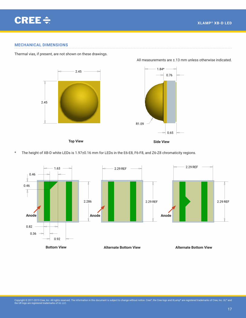
MECHANICAL DIMENSIONS
Thermal vias, if present, are not shown on these drawings.
All measurements are ±.13 mm unless otherwise indicated.
* The height of XB-D white LEDs is 1.97±0.16 mm for LEDs in the E6-E8, F6-F8, and Z6-Z8 chromaticity regions.
SIZE
TITLE
OF
REV.
SHEETC
DRAWING NO.
DATE
DATE
DATE
CHECK
FINAL PROTECTIVE FINISH
MATERIAL
APPROVED
DRAWN BY
THIRD ANGLE PROJECTION
SCALE
A
B
C
D
123456
6 5 4 3 2 1
A
B
C
D
Phone (919) 313-5300Fax (919) 313-5558
4600 Silicon DriveDurham, N.C 27703
UNAUTHORIZED PERSON WITHOUT THE WRITTEN CONSENTMAY NOT BE COPIED, REPRODUCED OR DISCLOSED TO ANY CONFIDENTIAL INFORMATION OF CREE, INC. THIS PLOT CONTAINED WITHIN ARE THE PROPRIETARY ANDCREE CONFIDENTIAL. THIS PLOT AND THE INFORMATION
OF CREE INC.
NOTICE
X° ± .5°.XXX ± .25.XX ± .75.X ± 1.5
FOR SHEET METAL PARTS ONLY
.XX ± .25
.XXX ± .125X° ± .5°
UNLESS OTHERWISE SPECIFIEDDIMENSIONS ARE IN
MILLIMETERS AND AFTER FINISH.TOLERANCE UNLESS SPECIFIED:
SURFACE FINISH: 1.6
2.45
2.45
1.84*
0.76
0.65
R1.09
0.36
0.92
2.286
1.63
0.46
0.46
0.82
2.29
0.33
0.36
2.29
0.92 0.85
0.39
2.29
2.29
0.85
0.250.85
0.17
2.29 REF 2.29 REF
2.29 REF
1/130.000D2610-00019
2525 SBC HEW OUTLINE
--
--
--
----
09/19/11D. CRONIN
REVISONSREV DESCRIPTION BY DATE APP'D B ADDED NOTCH TO BACKSIDE DC 10/16/12 C CORRECTED SOLDERPAD DIMENSION DC 7/1/15D ADDED ALTERNATE VIEWS DC 8/19/15
RECOMMENDED PCB SOLDER PADRECOMMENDED STENCIL PATTERN(HATCHED AREA IS OPENING)
PRIMARY ALTERNATIVE
ALL DIMENSIONS ARE ± .13 UNLESS OTHERWISE NOTED
2.29 REF
Top View Side View
SIZE
TITLE
OF
REV.
SHEETC
DRAWING NO.
DATE
DATE
DATE
CHECK
FINAL PROTECTIVE FINISH
MATERIAL
APPROVED
DRAWN BY
THIRD ANGLE PROJECTION
SCALE
A
B
C
D
123456
6 5 4 3 2 1
A
B
C
D
Phone (919) 313-5300Fax (919) 313-5558
4600 Silicon DriveDurham, N.C 27703
UNAUTHORIZED PERSON WITHOUT THE WRITTEN CONSENTMAY NOT BE COPIED, REPRODUCED OR DISCLOSED TO ANY CONFIDENTIAL INFORMATION OF CREE, INC. THIS PLOT CONTAINED WITHIN ARE THE PROPRIETARY ANDCREE CONFIDENTIAL. THIS PLOT AND THE INFORMATION
OF CREE INC.
NOTICE
X° ± .5°.XXX ± .25.XX ± .75.X ± 1.5
FOR SHEET METAL PARTS ONLY
.XX ± .25
.XXX ± .125X° ± .5°
UNLESS OTHERWISE SPECIFIEDDIMENSIONS ARE IN
MILLIMETERS AND AFTER FINISH.TOLERANCE UNLESS SPECIFIED:
SURFACE FINISH: 1.6
2.45
2.45
1.84*
0.76
0.65
R1.09
0.36
0.92
2.286
1.63
0.46
0.46
0.82
2.29
0.33
0.36
2.29
0.92 0.85
0.39
2.29
2.29
0.85
0.250.85
0.17
2.29 REF 2.29 REF
2.29 REF
1/130.000D2610-00019
2525 SBC HEW OUTLINE
--
--
--
----
09/19/11D. CRONIN
REVISONSREV DESCRIPTION BY DATE APP'D B ADDED NOTCH TO BACKSIDE DC 10/16/12 C CORRECTED SOLDERPAD DIMENSION DC 7/1/15D ADDED ALTERNATE VIEWS DC 8/19/15
RECOMMENDED PCB SOLDER PADRECOMMENDED STENCIL PATTERN(HATCHED AREA IS OPENING)
PRIMARY ALTERNATIVE
ALL DIMENSIONS ARE ± .13 UNLESS OTHERWISE NOTED
2.29 REF
Bottom View Alternate Bottom View
SIZE
TITLE
OF
REV.
SHEETC
DRAWING NO.
DATE
DATE
DATE
CHECK
FINAL PROTECTIVE FINISH
MATERIAL
APPROVED
DRAWN BY
THIRD ANGLE PROJECTION
SCALE
A
B
C
D
123456
6 5 4 3 2 1
A
B
C
D
Phone (919) 313-5300Fax (919) 313-5558
4600 Silicon DriveDurham, N.C 27703
UNAUTHORIZED PERSON WITHOUT THE WRITTEN CONSENTMAY NOT BE COPIED, REPRODUCED OR DISCLOSED TO ANY CONFIDENTIAL INFORMATION OF CREE, INC. THIS PLOT CONTAINED WITHIN ARE THE PROPRIETARY ANDCREE CONFIDENTIAL. THIS PLOT AND THE INFORMATION
OF CREE INC.
NOTICE
X° ± .5°.XXX ± .25.XX ± .75.X ± 1.5
FOR SHEET METAL PARTS ONLY
.XX ± .25
.XXX ± .125X° ± .5°
UNLESS OTHERWISE SPECIFIEDDIMENSIONS ARE IN
MILLIMETERS AND AFTER FINISH.TOLERANCE UNLESS SPECIFIED:
SURFACE FINISH: 1.6
2.45
2.45
1.84*
0.76
0.65
R1.09
0.36
0.92
2.286
1.63
0.46
0.46
0.82
2.29
0.33
0.36
2.29
0.92 0.85
0.39
2.29
2.29
0.85
0.250.85
0.17
2.29 REF 2.29 REF
2.29 REF
1/130.000D2610-00019
2525 SBC HEW OUTLINE
--
--
--
----
09/19/11D. CRONIN
REVISONSREV DESCRIPTION BY DATE APP'D B ADDED NOTCH TO BACKSIDE DC 10/16/12 C CORRECTED SOLDERPAD DIMENSION DC 7/1/15D ADDED ALTERNATE VIEWS DC 8/19/15
RECOMMENDED PCB SOLDER PADRECOMMENDED STENCIL PATTERN(HATCHED AREA IS OPENING)
PRIMARY ALTERNATIVE
ALL DIMENSIONS ARE ± .13 UNLESS OTHERWISE NOTED
2.29 REF
Anode AnodeAnode
Alternate Bottom View

Copyright © 2011-2019 Cree, Inc. All rights reserved. The information in this document is subject to change without notice. Cree®, the Cree logo and XLamp® are registered trademarks of Cree, Inc. UL® and the UR logo are registered trademarks of UL LLC.
18
XLAMP® XB-D LED
MECHANICAL DIMENSIONS - CONTINUED
SIZE
TITLE
OF
REV.
SHEETC
DRAWING NO.
DATE
DATE
DATE
CHECK
FINAL PROTECTIVE FINISH
MATERIAL
APPROVED
DRAWN BY
THIRD ANGLE PROJECTION
SCALE
A
B
C
D
123456
6 5 4 3 2 1
A
B
C
D
Phone (919) 313-5300Fax (919) 313-5558
4600 Silicon DriveDurham, N.C 27703
UNAUTHORIZED PERSON WITHOUT THE WRITTEN CONSENTMAY NOT BE COPIED, REPRODUCED OR DISCLOSED TO ANY CONFIDENTIAL INFORMATION OF CREE, INC. THIS PLOT CONTAINED WITHIN ARE THE PROPRIETARY ANDCREE CONFIDENTIAL. THIS PLOT AND THE INFORMATION
OF CREE INC.
NOTICE
X° ± .5°.XXX ± .25.XX ± .75.X ± 1.5
FOR SHEET METAL PARTS ONLY
.XX ± .25
.XXX ± .125X° ± .5°
UNLESS OTHERWISE SPECIFIEDDIMENSIONS ARE IN
MILLIMETERS AND AFTER FINISH.TOLERANCE UNLESS SPECIFIED:
SURFACE FINISH: 1.6
2.45
2.45
1.84*
0.76
0.65
R1.09
0.36
0.92
2.286
1.63
0.46
0.46
0.82
2.29
0.33
0.36
2.29
0.92 0.85
0.39
2.29
2.29
0.85
0.250.85
0.17
2.29 REF 2.29 REF
2.29 REF
1/130.000D2610-00019
2525 SBC HEW OUTLINE
--
--
--
----
09/19/11D. CRONIN
REVISONSREV DESCRIPTION BY DATE APP'D B ADDED NOTCH TO BACKSIDE DC 10/16/12 C CORRECTED SOLDERPAD DIMENSION DC 7/1/15D ADDED ALTERNATE VIEWS DC 8/19/15
RECOMMENDED PCB SOLDER PADRECOMMENDED STENCIL PATTERN(HATCHED AREA IS OPENING)
PRIMARY ALTERNATIVE
ALL DIMENSIONS ARE ± .13 UNLESS OTHERWISE NOTED
2.29 REF
Recommended PCB Solder Pad Recommended Stencil Pattern(Hatched Area is Opening)
SIZE
TITLE
OF
REV.
SHEETC
DRAWING NO.
DATE
DATE
DATE
CHECK
FINAL PROTECTIVE FINISH
MATERIAL
APPROVED
DRAWN BY
THIRD ANGLE PROJECTION
SCALE
A
B
C
D
123456
6 5 4 3 2 1
A
B
C
D
Phone (919) 313-5300Fax (919) 313-5558
4600 Silicon DriveDurham, N.C 27703
UNAUTHORIZED PERSON WITHOUT THE WRITTEN CONSENTMAY NOT BE COPIED, REPRODUCED OR DISCLOSED TO ANY CONFIDENTIAL INFORMATION OF CREE, INC. THIS PLOT CONTAINED WITHIN ARE THE PROPRIETARY ANDCREE CONFIDENTIAL. THIS PLOT AND THE INFORMATION
OF CREE INC.
NOTICE
X° ± .5°.XXX ± .25.XX ± .75.X ± 1.5
FOR SHEET METAL PARTS ONLY
.XX ± .25
.XXX ± .125X° ± .5°
UNLESS OTHERWISE SPECIFIEDDIMENSIONS ARE IN
MILLIMETERS AND AFTER FINISH.TOLERANCE UNLESS SPECIFIED:
SURFACE FINISH: 1.6
2.45
2.45
1.84*
0.76
0.65
R1.09
0.36
0.92
2.286
1.63
0.46
0.46
0.82
2.29
0.33
0.36
2.29
0.92 0.85
0.39
2.29
2.29
0.85
0.250.85
0.17
2.29 REF 2.29 REF
2.29 REF
1/130.000D2610-00019
2525 SBC HEW OUTLINE
--
--
--
----
09/19/11D. CRONIN
REVISONSREV DESCRIPTION BY DATE APP'D B ADDED NOTCH TO BACKSIDE DC 10/16/12 C CORRECTED SOLDERPAD DIMENSION DC 7/1/15D ADDED ALTERNATE VIEWS DC 8/19/15
RECOMMENDED PCB SOLDER PADRECOMMENDED STENCIL PATTERN(HATCHED AREA IS OPENING)
PRIMARY ALTERNATIVE
ALL DIMENSIONS ARE ± .13 UNLESS OTHERWISE NOTED
2.29 REF
Copyright © 2011-2019 Cree, Inc. All rights reserved. The information in this document is subject to change without notice. Cree®, the Cree logo and XLamp® are registered trademarks of Cree, Inc. UL® and the UR logo are registered trademarks of UL LLC.
19
XLAMP® XB-D LED
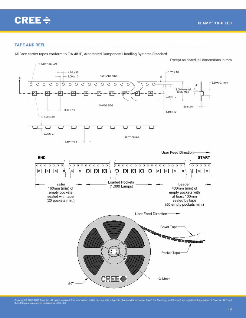
TAPE AND REEL
All Cree carrier tapes conform to EIA-481D, Automated Component Handling Systems Standard.
Except as noted, all dimensions in mm
SIZE
TITLE
OF
REV.
SHEETC
DRAWING NO.
DATEDATEDATE
CHECK
FINAL PROTECTIVE FINISH
MATERIAL
APPROVED
DRAWN BY
THIRD ANGLE PROJECTION
SCALE
A
B
C
D
123456
6 5 4 3 2 1
A
B
C
D
Phone (919) 313-5300Fax (919) 313-5558
4600 Silicon DriveDurham, N.C 27703
UNAUTHORIZED PERSON WITHOUT THE WRITTEN CONSENTMAY NOT BE COPIED, REPRODUCED OR DISCLOSED TO ANY CONFIDENTIAL INFORMATION OF CREE, INC. THIS PLOT CONTAINED WITHIN ARE THE PROPRIETARY ANDCREE CONFIDENTIAL. THIS PLOT AND THE INFORMATION
OF CREE INC.
NOTICE
X° ± .5°.XXX ± .25.XX ± .75.X ± 1.5FOR SHEET METAL PARTS ONLY
.XX ± .25.XXX ± .125X° ± .5°
UNLESS OTHERWISE SPECIFIEDDIMENSIONS ARE IN MILLIMETERS AND AFTER FINISH.TOLERANCE UNLESS SPECIFIED:
SURFACE FINISH: 1.6
BB
4°
8.00 ±.10
4.00 ±.102.00 ±.10
+.10/-.001.50
± .101.00
.30 ± .10
12.00 Nominal12.30 Max
5.50 ±.10
1.75 ±.10
10.25 ±.10
2.60+/-0.1mm
2.60 +/-0.1
2.05+/-0.1
REVISONSREV DESCRIPTION BY DATEAPP'D A Released DC 10/23/11JL B ADDED CATHODE AND ANODE NOTEDC 2/26/12C CHANGED POCKET DIMS AND TOLERANCESDC 8/3/12D CHANGED POCKET DIM TO INSIDE OF POCKET IN BOTTOM VIEWDC 2/1/18
1/14.000D2402-00020
Carrier Tape, 2525 HEW
10/23/11D. CRONIN
Notes:1. 10 sprocket hole pitch cumulative tolerance ± 0.2mm
REFERENCE VENDOR PART NUMBER 020246
CATHODE SIDE
ANODE SIDE
B-BSECTION
Loaded Pockets(1,000 Lamps) Leader
400mm (min) ofempty pockets with
at least 100mmsealed by tape
(50 empty pockets min.)
Trailer160mm (min) ofempty pockets
sealed with tape(20 pockets min.)
STARTEND
Cathode Side
Anode Side(denoted by + and circle)
160.0
A
A
B
2.5±.1
SECTION A-A SCALE 2 : 1
1.5±.1
8.0±.1
4.0±.1
1.75±.10
12.0 .0+.3
DETAIL B SCALE 2 : 1
13mm7"
Cover Tape
Pocket Tape
User Feed Direction
User Feed Direction

Copyright © 2011-2019 Cree, Inc. All rights reserved. The information in this document is subject to change without notice. Cree®, the Cree logo and XLamp® are registered trademarks of Cree, Inc. UL® and the UR logo are registered trademarks of UL LLC.
20
XLAMP® XB-D LED
PACKAGING
Patent Label(on bottom of box)
Label with Cree Bin Code, Quantity, Reel ID
Label with Cree Bin Code, Quantity, Reel ID
Label with Cree Order Code, Quantity, Reel ID, PO #
Label with Cree Order Code, Quantity, Reel ID, PO #
Label with Cree Bin Code, Quantity, Reel ID
Unpackaged Reel
Packaged Reel
Boxed Reel
CREE Bin Code& Barcode Label
Vacuum-SealedMoisture Barrier Bag
Label with CustomerP/N, Qty, Lot #, PO #
Label with Cree Bin Code, Qty, Lot #
Label with Cree Bin Code, Qty, Lot #
Vacuum-Sealed Moisture Barrier Bag
Patent Label
Label with Customer Order Code, Qty, Reel ID, PO #