creep-fatigue damage for boiler header stub mock-up
TRANSCRIPT

Creep-Fatigue Damage for Boiler Header Stub Mock-Up Specimen of 47Ni23Cr23Fe7W Alloy+1
Naoki Yamazaki1,+2, Kyohei Nomura1 and Keiji Kubushiro2
1Technology Platform Center, IHI Co., Ltd., Yokohama 235-8501, Japan2IHI ASIA PACIFIC (Thailand) Co., Ltd., Bangkok
Header stub welds for thermal power plants undergo creep-fatigue damage due to thermal expansion and contraction, which are caused bycyclic startup and shutdown of the plant. In this study, creep-fatigue tests were conducted using header stub mock-up specimens of 47Ni23Cr23Fe7Walloy to investigate the creep-fatigue damage process. It was discovered that the cracks were initiated from the outer surface of the tubenear the bond line, and they propagated toward the inner side in both fatigue and creep-fatigue tests. Transgranular cracks were observed infatigue tests, whereas cracks were found to be progressed along the grain boundary in creep-fatigue tests. The failure mechanism of 47Ni23Cr23Fe7W alloy header stub mock-up specimens was composed of two steps. At first, cracks progressed on the surface near the bond line, andthen progressed toward the inner surface. Crack initiation and propagation behaviors of the 47Ni23Cr23Fe7W alloy header stub mock-upspecimen were the same as those of the 2.25Cr1Mo steel header mock-up specimen. [doi:10.2320/matertrans.Z-M2020813]
(Received February 14, 2020; Accepted March 4, 2020; Published May 25, 2020)
Keywords: header stub, creep-fatigue, 47Ni23Cr23Fe7W alloy, 2.25Cr1Mo steel
1. Introduction
In the thermal power generation sector, efforts are beingmade to increase steam temperature with the aim ofimproving power generation efficiency and reducing CO2
emissions. For the A-USC (Advanced Ultra Super Critical)boiler currently under technology development, studies arebeing conducted on the use of Ni-based alloys instead ofconventional steel materials for some components such as themain steam piping from the standpoints of creep strength andhigh temperature corrosion because steam is superheated tomore than 700°C in this boiler. Toward the application ofNi-based alloys, element tests have been conducted wherebywelding and bending conditions were defined and then mock-up specimens were fabricated based on such conditions.1,2)
Moreover, the element tests were followed by actual boilertests using steam at temperatures of over 700°C, wherebyit was proved that the boiler was able to operate withoutproblems.3)
The next issue to be addressed for the A-USC boiler isthe establishment of maintenance technology toward itspractical use. Especially for parts that have seen damage inexisting boilers, we believe it is necessary to ascertain failuremechanisms and develop assessment techniques for theapplication of Ni-based alloys to them. Damage that hasoccurred in existing boilers includes creep damage of stubpiping, headers, etc.;4,5) creep damage of piping welds;6,7)
stress corrosion cracking of stainless steel circumferentialjoints;8) and reheat cracking of such joints.9) In addition,reheat cracking of girth welds of Ni alloy piping has beenexperienced in actual scale testing conducted in Europe,10)
and this fact suggests the importance of weld assessments.Hence, in order to ascertain the mechanisms of such damage,the following activities have been carried out for the alloy47Ni23Cr23Fe7W (HR6W), which is a prospective
material for the piping of A-USC boilers: creep assessmentsof headers and circumferential joints;11) unraveling ofdamage mechanisms through a large-scale creep test;12) anda study of reheat cracking and conditions for stress-reliefannealing.13) However, no studies have been conducted onstub welds heretofore. For ferritic heat resisting steels, whichare used in existing boilers, a study on the mechanismof damage resulting from creep fatigue was previouslyconducted, succeeding in the reproduction of damagemorphology.14) Thus, we believe this technique can be usedto unravel the process through which the stub welds of theA-USC boiler become damaged.
In this research, we therefore aimed to unravel themechanism of creep-fatigue damage of header stubs madeof Ni-based alloy. With this aim, we fabricated stub mock-upspecimens of HR6W and then conducted creep-fatigue testson them at a temperature of 750°C, to which they would beexposed in an actual A-USC boiler. Each creep-fatigue testconsisted of rupture testing and creep-fatigue interruptedtesting. First, the rupture testing was conducted to checkwhether the morphology of the damage accurately repre-sented the damage that might be suffered by an actual A-USCboiler. The creep-fatigue interrupted testing was thenconducted to study crack propagation behavior.
2. Test Methods
2.1 SpecimensStub mock-up specimens with the shape shown in Fig. 1
were fabricated by welding a small-diameter tube of HR6W(45mm in diameter, 9.3mm in thickness) to a plate of HR6W(50mm in thickness). Both the tube and the plate weresubjected to solution heat treatment and then TIG-welded toeach other. Alloy 617-based flux was used as the weldingconsumable. The tube-and-plate assembly was then subjectedto post weld heat treatment at 900°C for three hours13) toprepare for testing. For the purpose of comparison, smoothround-bar specimens were taken from a large-diameter tube,which were then subjected to high-temperature fatigue
+1This Paper was Originally Published in Japanese in J. Soc. Mater. Sci.,Japan 68 (2019) 136141.
+2Corresponding author, E-mail: [email protected]
Materials Transactions, Vol. 61, No. 6 (2020) pp. 1109 to 1114©2020 The Society of Materials Science, Japan
testing. The configuration of these specimens was as follows:10mm in diameter in the parallel section; 30mm in length.A test temperature of 750°C and five strain ranges (¦¾ =0.5%, 0.7%, 1.0%, 1.2%, 1.5%) were specified as the testconditions. Table 1 shows the chemical composition of thelarge-diameter specimens and the small-diameter specimens.
2.2 Methods of testing stub mock-up specimensFigure 2 shows a stub mock-up specimen in the testing
equipment. Uniaxial fatigue testing equipment was used. Theplate member of the stub mock-up specimen was fastened tothe U-shaped jig attached to the lower piston. In addition, thedistal tip of the small-diameter tube member was screwedinto the threaded hole located in the upper fixture having adiameter equal to that of the small-diameter tube and thenfastened. Due to the presence of about 0.1mm of playbetween the threaded hole and the small-diameter tube, the
amount of play was added to the displacement predeterminedfor testing. A bending load was then applied to the weld bondline on the small-diameter tube by moving the lower jig upand down. Displacement control was adopted as the testcontrol method out of consideration for the damage modes ofthe actual boiler.
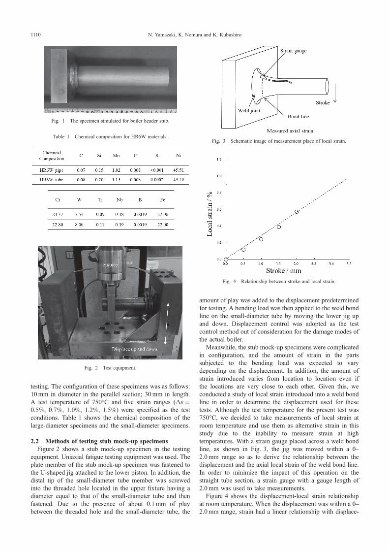
Meanwhile, the stub mock-up specimens were complicatedin configuration, and the amount of strain in the partssubjected to the bending load was expected to varydepending on the displacement. In addition, the amount ofstrain introduced varies from location to location even ifthe locations are very close to each other. Given this, weconducted a study of local strain introduced into a weld bondline in order to determine the displacement used for thesetests. Although the test temperature for the present test was750°C, we decided to take measurements of local strain atroom temperature and use them as alternative strain in thisstudy due to the inability to measure strain at hightemperatures. With a strain gauge placed across a weld bondline, as shown in Fig. 3, the jig was moved within a 02.0mm range so as to derive the relationship between thedisplacement and the axial local strain of the weld bond line.In order to minimize the impact of this operation on thestraight tube section, a strain gauge with a gauge length of2.0mm was used to take measurements.
Figure 4 shows the displacement-local strain relationshipat room temperature. When the displacement was within a 02.0mm range, strain had a linear relationship with displace-
Fig. 1 The specimen simulated for boiler header stub.
Table 1 Chemical composition for HR6W materials.
Fig. 2 Test equipment.
Fig. 3 Schematic image of measurement place of local strain.
Fig. 4 Relationship between stroke and local strain.
N. Yamazaki, K. Nomura and K. Kubushiro1110

ment. This relationship can be expressed by the followingequation:
¾ ¼ 0:2823� S� 0:0203 ð1Þwhere ¾ = local strain [%]; and S = displacement [mm]. Ito,et al. reported that they had conducted a test so that thenumber of cycles until the occurrence of damage would besomewhere between 500 to 1,000, taking into account thedamage process in an actual boiler. Based on eq. (1) andthe results of the preliminary testing described below, adisplacement of 3.0mm corresponding to a local strain rangeof 0.83% was extrapolated to conduct these tests.
Table 2 shows the test conditions determined for thepresent testing. A test temperature of 750°C was set for boththe fatigue testing and creep-fatigue testing. Each specimenwas heated by using the high-frequency induction heatingmethod while the temperature was controlled to keep thetemperature of the areas on both sides of the bond line onthe small-diameter tube (i.e., the small-diameter tube side andwelded metal side) within a 10mm range of the bond linewithin 750°C « 5°C. First, high-temperature fatigue testingwas conducted on stub mock-up specimens and the numberof cycles to failure was compared with the result of a uniaxialtest. This fatigue testing was followed by creep-fatiguetesting, wherein a displacement equal to that for the fatiguetesting was used. In addition, interrupted testing wasconducted at life ratios ranging from 17% to 61% using thesame specimens in order to ascertain crack propagationbehavior on their surfaces. After the testing had beeninterrupted, penetrant testing (PT) was conducted to ascertaincrack locations and measurements were taken of the lengthsof surface cracks at the respective life ratios. Moreover, inorder to ascertain the depths of cracks in the thicknessdirection, four specimens designed to fracture at a life ratio of38% to 100% were fabricated for interrupted testing and afractographic study was conducted on them. Measurementswere performed on each fracture surface obtained, in order todetermine the maximum length of the vertical section of thecrack propagation domain.
3. Results of Fatigue Testing of Stub Mock-Up Speci-mens
In order to determine the test conditions for these tests,stub simulation fatigue testing was conducted first aspreliminary testing. Figure 5 shows the curve of the numberof cycles to failure versus load at a test temperature of 750°Cand at a displacement of 3.0mm. Incidentally, due to theabsence of a clear definition of the number of cycles to failurefor stub-shaped specimens, “the number of cycles at themoment the tensile load decreases to 3/4 its peak value” wasdefined as the number of cycles to failure in line with thedefinition of Ito, et al.14) In the stub simulation fatigue
testing, a constant load was maintained within a certain rangeof cycles and then suddenly dropped, as seen in a uniaxialfatigue test of a general work hardened material. In addition,the calculated number of cycles to failure was 980.
Next, in order to make sure that the test conditions for thestub simulation testing were within the domain of low cyclefatigue testing, round bar specimens were taken from large-diameter tubes of HR6W and fatigue testing was conductedon them at 750°C. Figure 6 shows the obtained results. Thenumber of cycles to failure for the round bar specimens metthe standard of the Society of Materials Science, Japan.15) Ata strain range of 0.83%, the number of cycles to failure wasabout 750. Thus, the test conditions for the stub simulationfatigue testing were thought to be within the scope of lowcycle fatigue testing. Given this, a displacement of 3.0mmwas set as a test condition for creep-fatigue testing in thepresent research.
4. Results of Creep-Fatigue Testing of Stub Mock-UpSpecimens
4.1 Creep-fatigue testFigure 7 shows the curve of the load versus the number of
cycles to failure after creep-fatigue testing, wherein displace-
Table 2 Test conditions for stub mock-up specimens.
Fig. 5 Cycle-load curve for fatigue test.
Fig. 6 Relationship between the number of cycles to failure and strainrange.
Creep-Fatigue Damage for Boiler Header Stub Mock-Up Specimen of 47Ni23Cr23Fe7W Alloy 1111

ment continued to be applied for 60 minutes. The curveindicates that a constant load of approximately 17 kN wasmaintained within a certain range of cycles and then suddenlydropped. This result matches the trend of the load-numberof cycles relationship as seen in ordinary creep-fatiguetesting. In addition, the calculated number of cycles to failurewas 184.
4.2 Comparison of damage morphologyFigure 8 shows the appearance of specimens that under-
went stub simulation fatigue testing and the appearance ofspecimens that underwent creep-fatigue testing. Both speci-men groups showed that a crack formed near the bond line ofthe small-diameter tube and propagated along the bond line.In these tests, no cracks were found in areas distant from thebond line. Next, Fig. 9 shows the results of cross-sectionalobservation of crack propagation domains. Whereas thecracks that formed in the fatigue test specimens propagatedtransgranularly, the cracks in the creep-fatigue test specimenspropagated intergranularly. It seems that creep contributedto the difference in crack propagation route between thespecimen groups. A uniaxial creep-fatigue test of HR6Wdemonstrated that the creep propagation route varieddepending on the retention time16) and this result is consistentwith the result of the present testing.
4.3 Surface crack propagation behaviorIn order to understand crack propagation behavior on
surfaces, creep-fatigue interrupted testing was conductedon stub mock-up specimens. The same specimens wereconsistently used for testing. After the testing had beeninterrupted at each life ratio, PT was conducted on thespecimens. Figure 10 shows typical examples of the PTresults. In this connection, the number of cycles to failure forthis interrupted testing was defined as the number of cycles ata life ratio of 100%.
At the interruption at a life ratio of 17%, as shown in (a),PT indications attributable to cracks were not observed.Meanwhile, at the interruption at a life ratio of 24%, asshown in (b), microcracks were observed near weld bondlines. Thereafter, with an increase in life ratio, crack lengthincreased in the circumferential direction, as shown in (c) and(d).
Figure 11 shows the results of measurements of aggre-gated crack lengths at the respective life ratios. Cracksformed at a life ratio of around 20% and then rapidlypropagated along the circumference until the life ratioreached around 40%. Thereafter, crack lengths were nearlyconstant.
4.4 Crack propagation behavior in the thicknessdirection
Next, we conducted a study of crack propagation behaviorin the thickness direction from the formation of cracks untilthe occurrence of failure. For the purpose of creep-fatigueinterrupted testing wherein interruptions occurred at multiplelife ratios, we fabricated specimens for each life ratio.In order to observe fracture surfaces at the times ofinterruptions, we conducted room temperature fatigue testing
Fig. 7 Cycle-load curve for creep-fatigue test.
Fig. 8 Appearances of fractured specimens (a): After fatigue test (b):Larger image of (a) (c): After creep-fatigue test (d): Larger image of (c).
Fig. 9 Optical micrographs of cross section images for fractured specimens(a): After fatigue test (b)(c): Larger image of (a) (d): After creep-fatiguetest (e)(f ): Larger image of (d).
N. Yamazaki, K. Nomura and K. Kubushiro1112

whereby the fracture surfaces were opened. Figure 12provides photographs showing external views of the obtainedfracture surfaces, as well as those showing enlarged views ofthe oxidized regions in the fracture surfaces.
The opened fracture surfaces, including that of thespecimen for interruption at a life ratio of 38% as shown in(a), indicated the formation of cracks during the test and thepresence of oxidized regions localized on the outer surfaces.As shown in (b) through (d), the oxidized regions extended inthe thickness direction with an increase in life ratio. Theseoxidized regions matched the crack propagation domainsobserved in the creep-fatigue testing. We therefore tookmeasurements of the maximum length in the thicknessdirection of each oxidized region, thereby deriving relation-ships between life ratios and depths of crack propagation inthe thickness direction. Figure 13 shows the relationshipsbetween life ratios and crack depths in the thicknessdirection. Starting from a life ratio of around 40%, cracks
in the thickness direction monotonically propagated. Thenumber of cycles at a life ratio of 40%, at which such crackpropagation in the thickness direction was observed, closelymatched the number of cycles at the moment the tensile loaddecreased to 3/4 its peak value, as shown in Fig. 7. This fact,along with the surface crack propagation behavior shown inFig. 11, suggests that cracks formed by the creep-fatiguetesting started to propagate along the circumference first at alife ratio of around 20% and then propagated in the thicknessdirection starting from a life ratio of 40%, and finallyfractured. Given this, it is important during the maintenance
Fig. 10 Appearances of PT inspection under creep-fatigue interrupted tests(a): Life ratio: 17% (b) Life ratio: 24% (c) Life ratio: 41% (d) Life ratio:61%.
Fig. 11 Relationship between crack length on the surface and life ratiounder creep-fatigue test.
Fig. 12 Appearances of fracture surface after creep-fatigue interrupted tests(a): Life ratio: 38% (b) Life ratio: 43% (c) Life ratio: 61% (d) Life ratio:100%.
Fig. 13 Variation of crack depth with life ratio under creep-fatigue test.
Creep-Fatigue Damage for Boiler Header Stub Mock-Up Specimen of 47Ni23Cr23Fe7W Alloy 1113

of a header stub made of HR6W to check for crack initiationon the outer surface near the bond line.
4.5 Comparison of crack propagation behavior with2.25Cr1Mo steel
Creep-fatigue crack propagation behavior studied withstub mock-up specimens of 2.25Cr1Mo steel has beenreported by Ito, et al.13) Their report states that in the stubmock-up specimens of 2.25Cr1Mo steel, cracks formed onthe outer surfaces of the tubes and then propagated alongthe circumference first, then propagated in the thicknessdirection, and finally fractured. The crack propagationbehavior derived from the present testing was analogous tothat showed by 2.25Cr1Mo steel. Thus, a comparison wasmade between stub mock-up specimens of HR6W and thoseof 2.25Cr1Mo steel with regard to the relationships betweenlife ratios and depths of cracks in the thickness direction.Figure 14 shows the relationships between life ratios anddepths of cracks in the thickness direction for both HR6Wand 2.25Cr1Mo steel. In order to enable the data from thepresent testing to be directly compared with the data collectedby Ito, et al., values equal to a crack depth divided by thethickness of the small-diameter tube were assigned to thevertical axis. In addition, the number of cycles at the momentthe crack depth reached 25% of the thickness was redefinedas a life ratio of 100% and was assigned to the horizontalaxis. The crack depths relative to life ratios for the stubmock-up specimens of HR6W monotonically increasedstarting from a life ratio of 60%. This trend closely matchedthe results of the testing of stub mock-up specimens of2.25Cr1Mo steel. Although the reason for the consistencyin life-crack depth relationship between different materials isunknown, one possible reason for the consistency in crackformation and propagation behavior between these materialsis the contribution of stress concentration due to the stubconfiguration.
5. Conclusion
With the objective of understanding the creep-fatigueproperties and damage mechanism of stub mock-up speci-
mens of HR6W, we conducted fatigue testing and creep-fatigue testing. The following findings were obtained.(1) The stub mock-up specimens of HR6W showed a
0.83% local strain in the weld bond line whendisplacement was 3.0mm. This displacement waswithin the domain of low cycle fatigue testing of roundbar specimens.
(2) Creep-fatigue testing of stub mock-up specimensresulted in a constant load being maintained within acertain range of cycles and then suddenly dropping.This load drop was coincident with crack propagationin the thickness direction.
(3) The stub mock-up specimens of HR6W showed theoccurrence of a fracture near the bond line of the small-diameter tube in both fatigue testing and creep-fatiguetesting. In addition, the following findings wereobtained from cross-sectional observation: the fatiguetesting resulted in cracks propagating transgranularlywhile the creep-fatigue testing resulted in crackspropagating intergranularly.
(4) Creep-fatigue interrupted testing was conducted tostudy crack propagation behavior. As a result, it wasrevealed that cracks that formed in the stub mock-upspecimens of HR6W had propagated along the circum-ference first and then propagated in the thicknessdirection. In addition, this failure propagation behaviorwas analogous to that of specimens of 2.25Cr1Mosteel.
REFERENCES
1) K. Kubushiro, K. Nomura, H. Nakagawa and K. Muroki: IHI Eng. Rev.49 (2016) 3443.
2) T. Tokairin, K. Hashimoto, K. Kubushiro and M. Fukuda: Proc. NewAdvances in Material and Component Assesment 43rd MPA-Seminar,(2017).
3) Y. Okuma, K. Kubushiro, M. Kitamura, Y. Tachikana and M. Fukuda:Proc. New Advances in Material and Component Assesment 43rdMPA-Seminar, (2017).
4) J. Parker: Int. J. Press. Vessels Piping 114115 (2014) 7687.5) A. Shibli: Proc. 8th International Conference on Creep and Fatigue at
Elevated Temperatures, (2007) pp. 161170.6) W. Wang, X. Wang, W. Zhong, L. Hu and P. Hu: Procedia Mater. Sci. 3
(2014) 17061710.7) M. Al Hajri, A.U. Malik, A. Meroufel and F. Al-Muaili: Case Stud.
Eng. Failure Anal. 3 (2015) 96103.8) Y. Gao, C. Zhang, X. Xiong, Z. Zheng and M. Zhu: Eng. Fail. Anal. 24
(2012) 2632.9) A. Dhooge: Weld. World 41(3) (1998) 2630.10) European Commission: Component test facility for a 700°C power
plant (comets700), (2013) pp. 101105.11) K. Kubushiro, K. Tokuda and K. Nomura: Proc. 8th International
Conference on Advances in Materials Technology for Fossil PowerPlant, (2014).
12) K. Kubushiro, K. Nomura, H. Nakagawa, Y. Okuma and K. Muroki:Proc. International Conference on Power Engineering, (2015).
13) K. Kubushiro, K. Nomura, K. Tokuda and H. Nakagawa: Proc. 3rdInternational ECCC Conference, (2014).
14) T. Ito, I. Nonaka, H. Umaki, H. Nishida and S. Shintani: J. Soc. Mater.Sci. 52 (2003) 162166.
15) JSMS Committee on High Temperature Strength of Materials: Hightemperature low cycle fatigue test standard method, (2003).
16) K. Kubushiro, H. Yoshizawa, T. Ito and H. Nakagawa: Proc. 8thInternational Conference on Creep and Fatigue at Elevated Temper-atures, (2007).
Fig. 14 Change in depth of crack growth of HR6W and 2.25Cr1Mo steelfor creep-fatigue test.
N. Yamazaki, K. Nomura and K. Kubushiro1114