cross connection control manual - philadelphia · city of philadelphia water department...
TRANSCRIPT

CROSS CONNECTION CONTROL MANUAL
WATER DEPARTMENT
STANDARD SPECIFICATIONS
for
PREVENTION OF WATER CONTAMINATION

CITY OF PHILADELPHIA WATER DEPARTMENT
CROSS-CONNECTION CONTROL MANUAL
Cross Connection Control Guidelines- Issued 1978 Cross Connection Control Manual, 1st Edition - Issued 1988 Cross Connection Control Manual, 2nd Edition- Issued 1992 Cross Connection Control Manual, 3rd Edition - Issued 1994 Cross Connection Control Manual, 4th Edition - Issued 1998 Cross Connection Control Manual, 5th Edition - Issued 2004 Cross Connection Control Manual, 6th Edition - Issued 2006

DIRECTORY
WATER DEPARTMENT Cross-connection control requirements on Containment: Attn: Cross-connection Control Section Bureau of Laboratory Services 1500 E. Hunting Park Avenue Philadelphia, PA 19124-4941 (215) 685-1419, 1420 and 1407 Fax: (215) 743-5594 Water Main Records Meter Shop ARA Tower, 2nd Floor 29th & Cambria Streets 1101 Market Street Philadelphia, PA 19132 Philadelphia, PA 19107 (215) 685-9619 or 685-6300 (215) 685-6276 or 685-6300 Fax: (215) 685-9649 Fax: (215) 685-6312 LICENSES & INSPECTIONS Permits for domestic services & fire connections: Regarding Domestic Systems: Regarding Fire Protection Systems: Plumbing Unit Engineering Services Municipal Services Building Municipal Services Building 1401 JFK Blvd 1401 JFK Blvd Philadelphia, PA 19102 Philadelphia, PA 19102 (215) 686-2450, 2451 (215) 686-2470 and 2472 Fax: (215) 686-1407 Fax: (215) 686-2598 DEPARTMENT OF PUBLIC HEALTH Cross-connection control requirements on Elimination:
Environmental Health Services 321 University Avenue Philadelphia, PA 19104 (215) 685-7343, 7344, 7488 Fax: (215) 382-1210

TABLE OF CONTENTS CHAPTER TITLE PAGE GLOSSARY Definitions for Commonly used Cross Connections Terms 1 1.0 INTRODUCTION 4 1.1 Purpose of Manual 4 1.2 Cross Connection Control in the City of Philadelphia 4 2.0 POLICY 5 3.0 AUTHORITY 6 3.1 The Commonwealth of Pennsylvania 6 3.2 The Philadelphia Water Department 6 4.0 CONTAINMENT REQUIREMENTS 8 4.1 Backflow Protection at the Service Connection for 8 Containment 4.2 Listing of Facilities in which Backflow Protection is 9 Required at the Domestic Service 4.3 Backflow Protection for Fire Protection Systems 12 5.0 APPROVED BACKFLOW PREVENTION ASSEMBLIES 13 6.0 AIR GAP SEPARATION USING RECEIVING TANKS 14 7.0 INSTALLATION REQUIREMENTS 15 7.1 Mechanical Backflow Prevention Assemblies 15 8.0 TESTING AND MAINTENANCE 18 8.1 Backflow Prevention Assembly Testing 18 8.2 City Certified Backflow Technicians Responsibilities 18 8.3 Backflow Prevention Assembly Testing Procedures 20 9.0 APPENDIX 23
1
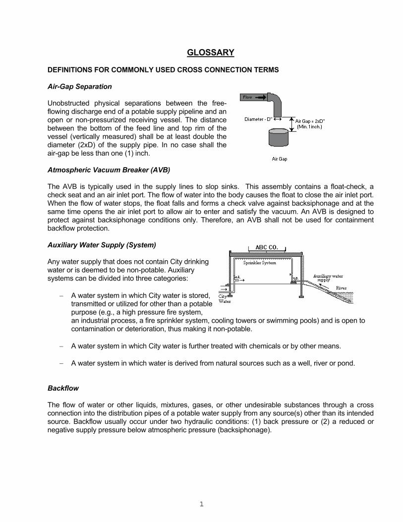
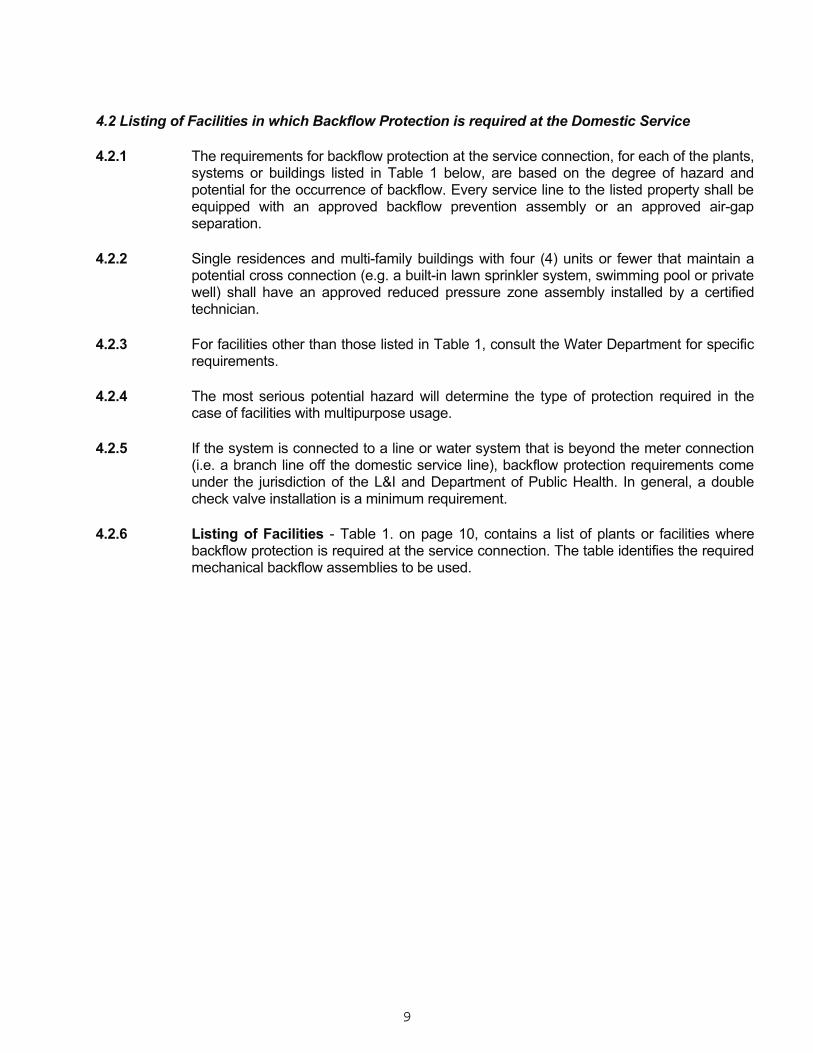
GLOSSARY DEFINITIONS FOR COMMONLY USED CROSS CONNECTION TERMS Air-Gap Separation Unobstructed physical separations between the free-flowing discharge end of a potable supply pipeline and an open or non-pressurized receiving vessel. The distance between the bottom of the feed line and top rim of the vessel (vertically measured) shall be at least double the diameter (2xD) of the supply pipe. In no case shall the air-gap be less than one (1) inch. Atmospheric Vacuum Breaker (AVB) The AVB is typically used in the supply lines to slop sinks. This assembly contains a float-check, a check seat and an air inlet port. The flow of water into the body causes the float to close the air inlet port. When the flow of water stops, the float falls and forms a check valve against backsiphonage and at the same time opens the air inlet port to allow air to enter and satisfy the vacuum. An AVB is designed to protect against backsiphonage conditions only. Therefore, an AVB shall not be used for containment backflow protection. Auxiliary Water Supply (System) Any water supply that does not contain City drinking water or is deemed to be non-potable. Auxiliary systems can be divided into three categories:
� A water system in which City water is stored, transmitted or utilized for other than a potable purpose (e.g., a high pressure fire system, an industrial process, a fire sprinkler system, cooling towers or swimming pools) and is open to contamination or deterioration, thus making it non-potable.
� A water system in which City water is further treated with chemicals or by other means.
� A water system in which water is derived from natural sources such as a well, river or pond.
Backflow The flow of water or other liquids, mixtures, gases, or other undesirable substances through a cross connection into the distribution pipes of a potable water supply from any source(s) other than its intended source. Backflow usually occur under two hydraulic conditions: (1) back pressure or (2) a reduced or negative supply pressure below atmospheric pressure (backsiphonage).

2
Backpressure Elevated pressure in the downstream piping system caused by pumping, elevation head, steam pressure or air pressure that exceeds the pressure in the supply piping. Backsiphonage Is the flowing back of non-potable water from a plumbing fixture or vessel into the drinking water supply due to a negative pressure within the connected drinking water supply system. City Certified Backflow Prevention Technician A City-licensed tradesman who is certified for installation, servicing and testing of backflow prevention devices. (See section 8.2) Containment A strategic approach of applying backflow protection on the service line to a facility, wherein contaminated water is contained within the facility and prevented from affecting other services connected to the same City water main. Contamination This is an impairment of potable water by the introduction or admission of any foreign substance that degrades the water quality and has the potential to create a health hazard.

3
Cross Connection Any physical connection or arrangement of pipes that allows the conveyances between potable and non-potable or questionable water source. Water may flow from one system to the other such that the potable water may become contaminated by the questionable source. Hose connections, bypass arrangements, jumper connections, removal sections, or changeover assemblies or any other temporary or permanent connecting arrangements through which backflow may occur are considered to be cross connections. The direction of flow depends on the pressure differential between the two systems. Double Check Valve Assembly (DCV) One of the type of backflow prevention assemblies which is composed of two independently acting check valves along with tightly closing shutoff valves attached at each end of the device and fitted with test cocks. A DCV assembly is used against backpressure and backsiphonage. In general, a double check valve assembly installation is used in minimum hazard systems. See list of Approved Double Check Valve Assemblies. Pressure Vacuum Breaker (PVB) This assembly contains an independently operating, internally loaded check valve and an independently operating, loaded air inlet valve located on the discharge side of the check valve. This assembly is equipped with test cocks and shutoff valves attached at each end of the assembly. This assembly is designed to protect against backsiphonage only. PVB assembly shall not be used for containment backflow protection. Reduced Pressure Zone Assembly (RPZ) A type of backflow prevention assembly, which contains two independently acting check valves together with a hydraulically operated, mechanically independent, pressure differential relief zone located between the check valves. The assembly includes test cocks and a tightly closing shutoff valve at each end. This assembly is effective against backflow caused by backpressure and backsiphonage. A reduced pressure valve assembly installation is used in high hazard systems. See list of Approved Reduced Pressure Zone Assemblies.

4
1.0 INTRODUCTION 1.1 Purpose of Manual This manual describes the Water Department's policy and the responsibility of each water customer pertaining to cross connection control. General and detailed information is presented in order to provide clear guidance for complying with the Department's cross connection control policy. 1.2 Cross Connection Control in the City of Philadelphia The City's Departments of Water, Licenses & Inspections and Public Health recognize that measures providing for reliable water treatment and conveyance do not necessarily guarantee safe water at the customer's tap because cross connections can exist. There have been numerous reported cases around the country where backflow through cross connections has been responsible for the contamination of a potable supply with disease-causing agents, toxic chemicals and other hazardous substances. In order to prevent contamination resulting from backflow, the Departments of Water, Licenses & Inspections and Public Health share responsibilities for cross connection control. Operational jurisdictions have traditionally been divided into two functional areas: containment and elimination. Containment, which is the concern of the Water Department and this manual, is designed to prevent any contamination on the customer's premises from affecting other customers through the City's water supply. In effect, contamination is "contained" within a facility and prevented from reaching the City main. Elimination of all unprotected cross connections within a facility, for the protection of that and other facilities, is the concern of the Department of Public Health. The Department of Licenses and Inspections administers both policies during the permitting and inspection processes. The Department of Water and Public Health also conduct inspections.

5
2.0 POLICY The Water Department is responsible for providing safe water to every customer at the service connection. In the exercise of this responsibility, the Department must take precautionary measures to protect the City's water distribution system from hazards originating on the premises of its customers which may degrade the community's water. These measures are borne out in the following policies: 2.1 All facilities shall have either an approved air-gap separation or an approved backflow prevention
device consistent with the degree of hazard, as defined by the Department, at the service connections. The backflow protection (in reference to Containment) shall be a properly installed air-gap separation, a double check valve assembly, or a reduced pressure zone assembly.
In addition, all fire systems shall have a Water Department approved reduced pressure zone
assembly or an approved double check valve assembly at the lines leading to the fire systems (Reference - Chapter 4, Containment Requirements).
2.2 The Department requires that the customer shall regularly provide for the testing and
maintenance of backflow devices by a certified backflow prevention technician at least once a year, in order to maintain them in operating condition or whenever failure is suspected. The customer shall also provide, through a certified backflow prevention technician, for the overhaul or replacement of such devices if they are found defective. The customer shall submit records of such tests, repairs, overhauls and replacements. to the Water Department's Cross Connection Control Section. Property owners shall be responsible for keeping records of such tests and related maintenance for a period of at least three (3) years.
2.3 Non-compliance with the preceding requirements after due notification may result in the
discontinuation of the water service. The customer may be required to reimburse the Department for all costs associated with such action. The Department may immediately terminate the water service to a facility if it is determined that a serious contamination potential exists.

6
3.0 AUTHORITY 3.1 The Commonwealth of Pennsylvania In the revised (October 23, 1984) Rules and Regulations of the Department of Environmental Protection, Section 109.709, it is stated: a. No person shall introduce contaminants into a public water supply through a service connection of a public water system. (1) It shall be the responsibility of the customer to eliminate cross-connections or provide
backflow devices to prevent contamination of the distribution system from both backsiphonage and backpressure. Individual backflow preventers shall be acceptable to the public water supplier.
(2) If the customer fails to comply with paragraph (1) within a reasonable period, the water
supplier shall discontinue service after reasonable notice has been made to the customer. b. At the direction of the Department, the public water supplier shall develop and implement a comprehensive control program for the elimination of existing cross-connections or the effective containment of sources of contamination, and prevention of future cross-connections. 3.2 The Philadelphia Water Department In the Philadelphia Water Department Regulations Section 403, (previously known as Regulation No. 77), it is stated: 3.2.1 Backflow protection at connections to the City water mains In order to protect the public water supply from potential cross connection and backflow hazards,
any connection to the City main, including both domestic and fire service connections within the property, shall be provided with adequate backflow protection by the property owner or the water user.
The requirements of this regulation shall generally apply to all water-using structures and
systems, regardless of their sizes, plumbing types and water usage patterns with the exception of single family residences and multi-family buildings with four (4) units or fewer. Where the Water Department has determined that backflow prevention measures are needed at any specific single family residence or multi-family building with four (4) units or fewer, this regulation shall also apply to those buildings. Backflow prevention measures include, but are not limited to, the following requirements:
(1) Any domestic and fire protection service line, including each line of a multiple service line to any
property, shall be equipped with an approved backflow prevention device or an approved air-gap separation on each line. Backflow prevention devices or air-gap separations must be installed where designated by the Water Department at the sole expense of the property owner. Backflow prevention devices or air-gap separations must be from an approved Water Department list or otherwise approved by the Water Department. Installers must refer to the latest edition of the Water Department Cross Connection Control Manual for installation requirements and listings of approved backflow prevention devices. This manual is available upon request from the Departments of Water and Licenses and Inspections.

7
(2) All other connections to the City main, including standpipes leading to elevated tanks, temporary
ferrules and hose connections shall be equipped with approved backflow prevention devices. (3) Only persons certified by the City's designated certification organizations shall install, test and
service backflow prevention devices. Installers are subject to all requirements of the Philadelphia City Code and regulations of the Water Department and the Department of Licenses and Inspections.
(4) Any newly installed backflow prevention device shall be tested prior to the initiation of service.
Backflow prevention devices shall thereafter be tested at least once a year or whenever failure is suspected. Backflow prevention devices must be maintained in proper operating condition at all times. The property owner shall be responsible for arranging for testing and for all costs of testing and related maintenance. Test results shall be submitted to the Water Department's Bureau of Laboratory Services. Property owners shall be responsible for keeping records of such tests and related maintenance for a period of three (3) years.
(5) The Water Department may shut off the water service to any premise and at any connection, if it
determines that there is inadequate backflow protection at the service connection and/or any connection to the main.
Note: In this manual hereafter, the term “backflow prevention assembly” will be used, which refers to the backflow prevention device and its strainer(s) as a unit.

8
4.0 CONTAINMENT REQUIREMENTS This chapter describes the Water Department's cross connection control requirements for all newly constructed and existing facilities. 4.1 Backflow Protection at the Domestic Service Connection for Containment 4.1.1 In order to protect the City's water supply from contamination that originates within a
customer's water system, an approved backflow prevention assembly (Refer to City Approved Backflow Assembly Listing) consistent with the degree of hazard or an approved air-gap separation (Refer to Section 6.0) shall be installed by the owner at the service connection on the outlet side of the meter at the owner's expense.
4.1.2 The degree of hazard is the Water Department's assessment of the potential harm that
may result from potential cross connections within a water-using facility. 4.1.3 High hazard denotes a potential threat of a cross connection problem that is physical,
chemical or biologically hazardous in nature. These pose a danger to the health and safety of the customer or the public.
4.1.4 Low hazard denotes a potential threat to the potability or physical properties of a potable
water system which could cause aesthetic problems or have a detrimental effect but which would not constitute a hazard to the health of the customer or the general public as defined.
4.1.5 A facility that has a high hazard potential or exhibits a high potential for the
occurrence of backflow shall have an approved reduced pressure zone assembly or an approved air gap separation, which conforms to the City's cross connection requirements.
4.1.6 A facility that has a low hazard potential shall have an approved double check valve
assembly which conforms to the City's cross connection requirements. 4.1.7 In order to provide guidance for designers of plumbing systems, the Water Department
has developed a list of systems, plants and buildings for which the backflow prevention requirements have been predetermined (see Section 4.2) based upon the degree of hazard and potential for the occurrence of backflow. For cases which are not listed or where there are questions about installation requirements, the Department will, provide a preliminary opinion on the specific containment requirements.
4.1.8 The customer shall provide for the regular testing of such backflow prevention devices or
air-gap separations at least once a year, or whenever failure is suspected, by a certified backflow prevention technician in order to maintain them in an operating condition. The customer shall also provide for the overhaul or replacement of such devices or air-gap separations by a certified backflow prevention technician if they are found defective. A record of such tests, repairs, overhauls and replacements shall be kept by the customer for a period of at least three (3) years and be submitted to the Water Department's Cross Connection Control Section. (See Chapter 8.0)
9
4.2 Listing of Facilities in which Backflow Protection is required at the Domestic Service 4.2.1 The requirements for backflow protection at the service connection, for each of the plants,
systems or buildings listed in Table 1 below, are based on the degree of hazard and potential for the occurrence of backflow. Every service line to the listed property shall be equipped with an approved backflow prevention assembly or an approved air-gap separation.
4.2.2 Single residences and multi-family buildings with four (4) units or fewer that maintain a
potential cross connection (e.g. a built-in lawn sprinkler system, swimming pool or private well) shall have an approved reduced pressure zone assembly installed by a certified technician.
4.2.3 For facilities other than those listed in Table 1, consult the Water Department for specific
requirements. 4.2.4 The most serious potential hazard will determine the type of protection required in the
case of facilities with multipurpose usage. 4.2.5 If the system is connected to a line or water system that is beyond the meter connection
(i.e. a branch line off the domestic service line), backflow protection requirements come under the jurisdiction of the L&I and Department of Public Health. In general, a double check valve installation is a minimum requirement.
4.2.6 Listing of Facilities - Table 1. on page 10, contains a list of plants or facilities where
backflow protection is required at the service connection. The table identifies the required mechanical backflow assemblies to be used.

10
LEGEND: 1 Reduced Pressure Zone Assembly 2 Double Check Valve Assembly 3 Five units or more with a common water service line 4 Examples of Systems with high hazard potential for the occurrence of backflow:
- Sump systems, sewer ejecting or sewer connected systems, sewage pumping, swimming pool, well, chilled-water, air conditioning systems equipped with cooling tower and circulation units, steam generation, boiler, built-in lawn sprinklers, heat exchanger or water treatment units (e.g. water softener). High-rise building (e.g., four floors or more), booster pump, hydraulically operated equipment, water storage tank, multi-purpose building (e.g. mall).

TABLE 1. LISTING OF FACILITIES DEVICE TYPE No A. Plant or System RPZ1 DCV2
1 Aircraft and Missile Plant x2 Automatic Car Wash x3 Automotive Plant x4 Auxiliary Water system x5 Beverage Bottling Plant x6 Brewery/Distillery x7 Cannery, Packing House and Reduction Plant x8 Chemical Plant(Manufacturing, Processing, Compounding, or Treatment x 9 Dairy and Cold Storage Plant x
10 Dye Handling or Processing x11 Film Processing x12 Irrigation System (Green House, Park, Golf Course, Playground, Estate, Cemetery etc.) x 13 Laboratory x14 Laundry A. Commercial B. Laundromat x15 Manufacturing, Processing, and Fabrication Plant x17 Metal Plating Plant x18 Public Transportation Facility (Airport, Bus or Train Station, etc.) x 19 Pulp and Paper Products Plant x20 Petroleum or Gas Processing or Storage Plant x21 Plating Plant x22 Power Plant (Heating/Ventilation/Refrigeration or Commercial Power) x 23 Radioactive Materials or Substances x24 Rubber Plant (Natural or Synthetic, Processing Plant or Facility Handling, Mfg. Rubber Goods or Tires) x 25 Sand and Gravel Plant (Sand and Gravel Washing or Cement or Concrete Processing) x 26 Sewage or Stormwater Treatment/ Wastewater Processing/Ejector Pumping or Handling Survey Facility x 27 Water Front Facility & Industry x28 Facility where a Cross Connection is to be Maintained x 29 Facility where security requirements or Other Prohibiting restrictions make it impossible to complete a CCC survey x B. Building
30 Apartment Complex3 with a Low Hazard Potential for the Occurrence of Backflow x 31 Apartment Complex with a High Hazard Potential for the Occurrence of Backflow4 x 32 Commercial Buildings including Warehouses x33 Food Handling Establishments including Restaurants x 34 Laboratory x35 Medical Facilities including Hospitals, Clinics, Nursing Homes and Dialysis Units x 36 Morgue and Mortuary x37 Motel and Hotel x38 Multi-Purpose Building x39 Office Building with a Low Hazard Potential for the Occurrence of Backflow x 40 Office Building with a High Hazard Potential for the Occurrence of Backflow4 x 41 Public Building (Federal/State/City/Government) with a Low Hazard Potential for the Occurrence of Backflow x 42 Public Building with a High Hazard Potential for the Occurrence of Backflow4 x 43 Religious buildings (Church, Temple) with a Low Hazard Potential for the Occurrence of Backflow x 44 School, Colleges x45 Supermarket x C. Private Mains (See Appendix)
46 Apartment Complex3 with a Low Hazard Potential for the Occurrence of Backflow x47 Apartment Complex with a High Hazard Potential for the Occurrence of Backflow4 x 48 Commercial Building Complex x49 Industrial, Office & Public Facilities(Federal/State/City/Quasi-Government) x 50 Multi-Purpose x D. Fire System Description
51 Fire system directly connected to City main x 52 Fire system with various chemical additives and/or auxiliary sources x 53 Fire connection on a metered domestic service x 54 Fire connection on a metered domestic service with various chemical additives and/or auxiliary sources x

12
4.3 Backflow Protection for Fire Protection Systems 4.3.1 Any fire sprinkler system, which is directly connected to the City main, shall be equipped with
an approved double check valve (DCV) at the line leading to the sprinkler system. 4.3.2 An approved reduced pressure zone assembly (RPZ) will be required for sprinkler systems that
constitute a significant backflow hazard or systems with a high potential for the occurrence of backflow. These include:
- Sprinkler systems which use foaming substances, antifreeze solutions or biostatic or
chemical additives;
- Facilities which have auxiliary water sources (see Glossary) suitable for fire fighting systems which are connected or available to the sprinkler systems.
- (Note: Facilities in which the fire Siamese connection is within 700 feet of a non potable standing water source such as a pond, creek or river, must consult the Water Department regarding appropriate backflow protection.)
4.3.3 All new underground piping and lead-in connections on the inlet side of the listed backflow
prevention device shall be cement lined ductile iron or copper pipe. Piping for the fire suppression system on the outlet side of the listed backflow prevention device may be of any material permitted by the appropriate installation standard referenced by the 2004 Philadelphia Building Code.
(Note: Consult the Fire Department for the usage of antifreeze or other chemical additives in wet systems and unheated rooms.)

13
5.0 APPROVED BACKFLOW PREVENTION ASSEMBLIES All backflow prevention assemblies must be selected from the City’s approved listing of Reduced Pressure Zone (RPZ), Double Check Valve (DCV), Reduced Pressure Zone Detector (RPZD) and Double Check Valve Detector (DCVD) assemblies. This list is updated periodically with the modification, addition or deletion of backflow prevention assemblies. The approval process for these assemblies is based on the standards of USC and other nationally recognized agencies. The current approved list is an appendix separate from this manual, and can be obtained from the Water Department’s Cross Connection Control unit or its web page.

14
6.0 AIR-GAP SEPARATION USING RECEIVING TANKS 6.0.1 The receiving tank shall be installed within the building and close to the service connection
(meter). The supply line between the meter and the tank shall be permanently exposed for inspection purposes. A facility with an air-gapped system which is located away from the service connection (e.g. a holding tank on the roof) must provide containment protection at the service connection.
6.0.2 There shall be no outlet, tee, tap or connection of any kind to or from the supply pipe between the
meter and the opening from which the water is discharged into the receiving tank. 6.0.3 The free flowing discharge point shall be located at a distance of not less than two times the
diameter of the inlet pipe (minimum one inch) above the flood rim of the tank.

15
7.0 INSTALLATION REQUIREMENTS Drawings in the appendix illustrate the installation design standards for air-gap separation, mechanical devices and the water metering requirements. The same or similar methods as shown should be used and a City certified backflow prevention technician MUST do all work. 7.0.1 Prior to the installation of any backflow prevention assembly, the technician must apply for a
permit and submit drawings to L&I offices for approval. Any variances from typical installations must obtain approval from the Cross Connection Control section of the Philadelphia Water Department.
7.0.2 Prior to the installation of any containment backflow prevention assembly, the technician may
need to caution the owners of certain facilities that the installation of a backflow prevention assembly may create a closed system, thereby creating the potential for thermal expansion pressure build-up.
7.0.3 Prior to installation, backflow prevention assemblies must be selected from the current City-
approved listing maintained by the Water Department. If any unapproved backflow prevention assembly is found on any water service connection, that assembly shall be removed and replaced with a City approved assembly.
7.0.4 Prior to installation, the water line shall be thoroughly flushed to expel all debris. Especially with
the RPZ assembly, debris lodging under one of the check valves is one of the most common causes of malfunctioning assemblies.
7.0.5 No backflow prevention assembly shall be installed creating a safety hazard (i.e. installed over an
electrical panel, steam lines, boilers, or within a ceiling). 7.1 Mechanical Backflow Prevention Assemblies
All backflow prevention assemblies shall be installed in a HORIZONTAL ORIENTATION, unless stated otherwise in the City's latest approved listing, and in accordance with the manufacturer's specifications and the following Water Department instructions: 7.1.1 The backflow unit shall be maintained as an assembly. The backflow assembly shall be
equipped with proper shutoff valves, attached to the device, for maintenance and testing. Shutoff valves shall be the type that are supplied by the same backflow preventer manufacturer or the type that are approved or manufactured to conform to standards set by AWWA, USC, FCCC, ASSE, or UL/FM. Approved assemblies should be shipped from the manufacturer with shutoff valves and test cocks. The assembly shall not be approved without proper shutoff valves and test cocks.
7.1.2 There shall be no outlet, tee, tap or connection of any kind to or from the supply pipe
between the meter or connection to the main when the meter is not present, and the backflow prevention assembly. If a takeoff is necessary, it must be equipped with the proper PWD approved backflow prevention assembly.
7.1.3 An approved backflow prevention assembly when installed within the building on the service
connection shall be located after but close to the meter. If a backflow prevention assembly is required to be installed outdoors, for domestic systems, the device must be installed within 100 ft of the meter. The assembly shall be protected from freezing, flooding and vandalism. Access for routine testing and maintenance shall be provided.

16
7.1.4 For existing fire systems, the backflow prevention assembly must be as close to the point of
entry of the service as possible. In addition, the pipe run to the backflow prevention assembly from the water main shall be less than 100 ft. For new fire systems the backflow prevention assembly must be located as close to the water main as possible.
7.1.5 In some facilities, backflow prevention assemblies installed in parallel on a service line may
be necessary to meet the needs of the facility: 1) If a facility requires continuous uninterrupted service and it is not possible or practical to
provide water service from two separate service lines into the premises, provisions must be made for the installation of two backflow prevention assemblies in parallel.
2) Installing parallel assemblies may be required when the water service line to be protected
is greater than 10" in diameter. 3) If a parallel or by-pass installation is desired, both lines shall be equipped with two same-
type backflow prevention assemblies. The combined hydraulic capacity of the parallel lines/devices shall be equal to or greater than that of the line that is being subdivided. Closed gate valves on the bypass do not constitute protection.
7.1.6 When a backflow prevention assembly is located inside a building, there must be a suitable
means of addressing any discharge without creating a safety or nuisance problem. If an RPZ assembly is to be installed, considerable measures must be taken to provide drainage for the relief-valve port. An RPZ assembly will spill or discharge water under some normal and most abnormal operating conditions. There must be a fixed air gap between the relief port and the drain.
7.1.7 Where siting problems prevent installation, as specified in Sections 7.1.2 - 7.1.6, the
Departments of Water and/or Licenses & Inspections may approve an alternate installation provided that a written request is presented to the Water Department or L&I. All alternative installations must provide at least the same level of backflow protection as the standard installation.
7.1.8 The requirements for installation of backflow prevention assemblies at alternative locations,
in lieu of the service connection within a building, are given below. 7.1.9 Beyond the Service Connection 1) Indoor Installations (a) An approved backflow prevention assembly may be installed on the discharge side of a
pump system when a customer's water-pump system experiences or could experience operational problems due to low City-water pressures in the area surrounding the building.
(b) There shall be no outlet, tee, tap or connection of any kind to or from the supply line
between the meter and the assembly. In situations where a meter is not required, there shall not be any between the assembly and the connection to the water main. If a takeoff is necessary, it must be equipped with a proper backflow prevention assembly designated by the Water Department.

17
2) Outdoor Installations (a) RPZ Installation An RPZ must be installed above ground with a minimum 12" clearance (the distance
between the ground level and the bottom of the assembly) so that it will not become submerged and can drain freely from the atmospheric port. An on-site constructed or pre-manufactured shelter must be installed to provide additional protection against freezing and vandalism.
(b) DCV Installation Preferably, all DCVs should be installed above ground. However, if a DCV needs to be
installed below ground level it must be located in a pit (vault) or chamber that is designed to prevent flooding. If the installation is made in a meter (master) pit, the designer shall follow the Water Department's Meter Pit Standards. (See Appendix, Meter Installation Standards)
All backflow prevention assembly installations in pits or chambers must adhere to the
following provisions: (i) There shall be no outlet, tee, tap or connection of any kind to or from the supply line
between the meter and the backflow prevention assembly. In situations where a meter is not required, there shall not be any between the assembly and the connection to the water main.
(ii) The assembly shall be protected against freezing. Access for routine testing and
maintenance shall be provided. (iii) If a drain in the pit or chamber is absolutely necessary there shall be no connection
between the drain and a sewer or appurtenance that permits the passage of polluted water into the pit or chamber.
(iv) The pit shall be maintained free of standing water so the DCV is not submerged.

18
8.0 TESTING AND MAINTENANCE 8.1 Backflow Prevention Assembly Testing All containment backflow prevention assemblies shall be tested and maintained to insure continued reliability. Tests shall be made within fourteen (14) working days of initial installation, after each repair and annually thereafter. Refer to Philadelphia Water Department Regulations mentioned on page 6. All reports on the testing of each assembly giving pertinent test data and repairs (if any) that were made, are to be documented using the Water Department's form No. 79-770 "Backflow Prevention Assembly Test and Maintenance Record." All assemblies failing to meet the Water Department's performance standards (Refer to Testing Procedures, Section 8.3 on page 20) shall be repaired or replaced and retested promptly. All repairs and replacements must be completed within fourteen (14) days from the initial test. Assemblies, which are found to have a history of not meeting the Water Department's performance standards, should be placed on a semi-annual or quarterly testing schedule. City certified backflow prevention assembly technicians shall perform Backflow prevention testing and maintenance. These certified individuals are trained and competent in this specialized area. An updated listing of the City certified technicians is made available at the Water Department and L&I offices listed in the DIRECTORY, and also will be available on the Water Department web page. All backflow assembly test kits used to test backflow prevention assemblies should be calibrated on a yearly basis. The calibration results of test kits should be recorded and submitted to the Water Department's Cross Connection Control Section at the address listed in the DIRECTORY. 8.2 City Certified Backflow Technician To become a City certified backflow technician, the applicant must successfully complete the four day Backflow Prevention Assembly Technician Training and Certification Course offered in Philadelphia by the New England Water Works Association (NEWWA) or the American Society of Sanitary Engineering (ASSE) and must register with PWD. To qualify for the City approved backflow prevention technicians listing, the PWD Certified Backflow Assembly Technician Registration Form (CR100) must be filled out and submitted to PWD. Certification shall be renewed every three years. 8.2.1 All cross connection control (CCC) work for domestic service systems must be
performed by a certified backflow technician employed as either a City licensed Registered Master Plumber (RMP) or a City licensed Journeyman Plumber. Journeyman Plumbers must work under the supervision of an RMP who is a certified backflow technician. After testing of a containment assembly the results must be signed by a certified RMP and sent to the Water Department.
8.2.2 All CCC work for fire suppression systems must be performed by a certified backflow
technician employed by a City licensed fire suppression contractor (FSC). The backflow technician is required to possess a Department of Licenses & Inspections Class 1-fire suppression systems certificate. After testing of a containment assembly the results must be signed by a certified FSC and sent to the Water Department.

19
8.2.3 The City certified backflow technician has the following responsibilities when employed
by a customer to install, test, repair or maintain any backflow prevention assembly:
� Consult with either the Water Department or L&I offices for approval prior to the installation of any backflow prevention assembly.
� Ensure that the City's testing procedures are used for testing, repairing and maintaining
any backflow prevention assembly (Refer to Section 8.3, Approved Testing Procedures).
� Provide copies of reports of such testing and/or repair for the customer on form #79-
770 - Backflow Prevention Assembly Test and Maintenance Record. The certified technician must include the list of any materials or replacement parts used to repair an assembly.
� Replacement parts must be equal in quality to the parts originally supplied by the
manufacturer of that assembly.

20
8.3 Backflow Prevention Assembly Testing Procedures The following procedures SHALL be used when testing backflow prevention devices: 8.3.1 Test procedure for RPZ assemblies 1. Close No. 2 gate valve
on device and observe relief valve for discharge of water. (Discharge would indicate the first check valve is not holding.)
2. Flush test cocks to
remove rust, debris, etc. 3. Close valve "A" (high)
and valve "C" (low) on test kit. Valve "B" (vent) should be open.
a) Test first check valve for minimum 5 PSI static pressure drop: 1. Connect high-pressure hose to #2 test cock and low pressure hose to #3 test cock. 2. Open #2 test cock and #3 test cock. 3. Slowly open valve "A" (high) and bleed air and water through vent hose; close
valve "A". 4. Slowly open valve "C" (low) and bleed air and water through vent hose. Close
valve "C" and observe differential pressure on gauge (should read a minimum of 5 PSID.)
b) Test second test check valve for tightness against reverse flow: 1. Connect vent hose to #4 test cock and turn on #4 test cock. 2. Open valve "A" and observe gauge reading and relief valve for discharge. 3. The differential pressure reading on the gauge will drop slightly and then remain
steady. If the gauge reading continues to drop (until the relief valve discharges), it indicates that the second check valve is leaking.
c) Test gate valve #2 for tightness: 1. Close #2 test cock. If the pressure differential decreases (approaching zero) the #2
gate is reported to be leaking. 2. Open #2 test cock.

21
NOTE: If gate valve #2 is leaking, test "A" and test "B" are invalid. A jumper hose or another shut
off valve downstream of the device must be utilized. d) Test operation of the differential pressure relief valve:
1. Close valve "B" (vent), (optional). Valve "A" should be open. 2. Very slowly open "C" (low) valve until the differential gauge needle starts to drop.
Note the pressure reading when the relief valve starts to discharge. This gauge reading must be at least 2 PSI.
e) Test conclusion 1. Open #2 gate valve. 2. Close all test cocks. 3. Disconnect VENT hose from test cock #4. 4. Open valves "A", "B" and "C" to drain water pressure from the test gauge. 5. Remove hoses from test cocks #2 and #3 and drain remaining water in the gauge
to prevent freezing.

22
8.3.2 Test procedure for DCV assemblies 1. Close downstream shut-off "B". (Test kit "high" and "low" hose needle valves closed and
"vent" hose needle open). 2. Attach "high" hose to test
cock #2. 3. Attach "low" hose to test cock
#3. 4. Open test cocks #2 and #3. 5. Bleed the air from the "high"
hose. (Open the test kit high needle and bleed water through the vent hose to a bucket).
6. Bleed the air from the "low"
hose. (Open the test kit low needle and bleed water through the vent hose to a bucket). Slowly close the needle valve.
7. Read the differential pressure on the gauge. A minimum of 1 PSID is acceptable. 8. Repeat the above test procedure (steps #2 through #6) for testing the second check, i.e.,
move the hoses over with the "high" hose on test cock #3, and the "low" hose on test cock #4. Read the differential pressure on the gauge. A minimum of 1 PSID is acceptable.
9. Remove the test hoses, drain the test kit, and turn the water back on (open downstream
shut-off B).

23
9.0 APPENDIX Page 9.1 General Notes I-1 9.2 Air-Gap Separation, Indoor Installation I-2 9.3 Double Check Valve (DCV) Assembly 9.3.1 Indoor Installation, N.R.S or O.S.& Y. Valves I-3 For meters sizes less than 3” 9.3.2 Indoor Installation, N.R.S or O.S.& Y. Valves I-4 For meters sizes less than 3” 9.3.3 Indoor Installation, N.R.S or O.S.& Y. Valves I-5 3” to 10” Pipe size 9.3.4 Indoor Installation, N.R.S or O.S.& Y. Valves I-6 For meter sizes 3” or greater 9.3.5 Indoor Installation, N.R.S or O.S.& Y. Valves I-7 For meter sizes 3” or greater 9.3.6 Indoor Installation, N.R.S or O.S.& Y. Valves I-8 For meter sizes less than 3” 9.3.7 Outdoor Installation, N.R.S or O.S. & Y. Valves I-9 For meter sizes less than 3” 9.3.8 Outdoor Installation, N.R.S or O.S. & Y. Valves I-10 Below Ground 9.3.9 Outdoor Installation, N.R.S or O.S. & Y. Valves I-11 Above Ground 9.3.10 Outdoor Installation, N.R.S or O.S. & Y. Valves I-12 Above Ground 98.3.11 Outdoor Installation, N.R.S or O.S. & Y. Valves I-13 Above Ground Only 9.4 Reduced Pressure Zone (RPZ) Assembly 9.4.1 Indoor Installation, N.R.S. or O.S.& Y. Valves I-14 For meter sizes less than 3” 9.4.2 Indoor Installation, N.R.S. or O.S.& Y. Valves I-15 For meter sizes less than 3” 9.4.3 Indoor Installation, N.R.S. or O.S.& Y. Valves I-16 3” to 10” Pipe Size 9.4.4 Indoor Installation, N.R.S. or O.S.& Y. Valves I-17 For meter sizes 3” or greater 9.4.5 Indoor Installation, N.R.S. or O.S.& Y. Valves I-18 For meter sizes 3” or greater 9.4.6 Indoor Installation, N.R.S. or O.S.& Y. Valves I-19 For meter sizes less than 3” 9.4.7 Outdoor Installation, N.R.S. or O.S.& Y. Valves I-20 Above Ground Only 9.4.8 Outdoor Installation, N.R.S. or O.S.& Y. Valves I-21 Above Ground Only

24
9.4.9 Outdoor Installation, N.R.S. or O.S.& Y. Valves I-22 Above Ground Only 9.5 Outdoor Installation, Above Ground Only I-23 Commercially Available Pre-fabricated Shelter 9.6 Outdoor Installation, Above Ground I-24 Pre-cast or Cast In Place Concrete Shelter 9.7 New Construction; Backflow Protection for I-25 Private, Domestic and Fire Water Services 9.8 Existing Facilities; Retro-fitting Existing Private I-26 Domestic and Fire Water Services for Backflow Protection 9.9 Fire Systems Containment I-27 to I-31 9.10 Meter Installation Standards Dwg-1 to Dwg-8