crown land bridge management guidelines - abiriv.com · crown land bridge management guidelines ......
TRANSCRIPT

Crown Land Bridge Management Guidelines February 2008
Ministry of Natural Resources
CROWN LAND BRIDGE MANAGEMENT GUIDELINES
TABLE OF CONTENTS 1. Introduction 1.1 Background ............................................................................................................................ 1 1.2 Objectives ................................................................................................................................ 1 1.3 Legislation and Regulations Pertaining to Roads on Crown Land.................................... 2 1.4 Guiding Principles .................................................................................................................. 4 1.5 Role of the Canadian Highway Bridge Design Code ........................................................... 5 2. Definitions ...................................................................................................................................... 6 3. Policy Statements ....................................................................................................................... 7 4. Standards for Permanent Bridges 4.1 Structural Standards ............................................................................................................. 8 4.2 Other Standards .................................................................................................................... 9 4.3 Material and Construction Standards ............................................................................... 11 5. Standards for Temporary Bridges ............................................................................................. 12 6. Standards for Inspecting Existing Bridges ............................................................................. 13 7. Standards for Bridge File Records ........................................................................................... 14 8. Application and Approval Process ........................................................................................... 15 9. Use of MNR Standard Bridge Design Drawings 9.1 The Advantages of Standard Bridge Designs ................................................................... 15
9.2 The Limitations of MNR Standard Bridge Designs ........................................................... 16
APPENDICES
Appendix A – Application Form and Application Information Checklist ........................................ 17 Appendix B – Approval Process for CFSA Authorized Bridges ....................................................... 23 Appendix C – Bridge Design Record Form ........................................................................................ 25 Appendix D – MNR Suggested Methods for Estimating Design Flow .............................................. 27 Appendix E – Inspection Guidelines and Checklist ......................................................................... 28 Appendix F – Information for Bridge File Record .............................................................................. 34 Appendix G – MNR Standard Design Drawings ................................................................................. 36

1
1. INTRODUCTION 1.1 Background In 1989, in collaboration with the forest industry, the Ministry of Natural Resources (MNR) adopted a policy governing the design, construction, inspection and maintenance of bridges on Crown land. Known as the “Report on Crown Land Bridge Management”, the policy had its basis in the Ontario Highway Bridge Design Code of the day but it allowed variation from the code for bridges with a low-traffic volume, where public and worker safety were not at risk. The policy was implemented by MNR using the same legislation and regulations that are used to authorize the construction of roads and bridges on Crown land. It is recognized that these roads are not highways and there are certain inherent risks for users of Crown land roads, particularly roads used for forest operations. There has been enough change in the intervening years to require the old policy to be updated. The Ontario Highway Bridge Design Code has since been replaced by the Canadian Highway Bridge Design Code as the basis for bridge building in Canada. Portable bridges, which were not addressed specifically in the 1989 policy, have become increasingly common on Crown land as a means of reducing the environmental impacts of road access and the high cost of wood delivery. And, with the conversion of virtually all of the remaining Crown forest management units to sustainable forest licences, the forest industry is now directly responsible for more bridges on Crown land than is MNR itself. As in 1989, the new bridge standards are the result of a collaborative effort with the forest industry. A group of MNR employees and forest industry representatives have spent the last two years developing the bridge standards that appear in this report. The purpose of these guidelines is to ensure that Ontario’s Crown land bridge practices are safe, while at the same time allowing the owners of the bridges to achieve every reasonable economy. 1.2 Objectives The goal of MNR’s bridge policy is to ensure that bridges on Crown land roads are safe for workers, the public and the loads they carry. The policy’s objectives are:
a) to specify the standards and management practices that apply to bridges on Crown land roads,
b) to set out the role of MNR in reviewing and approving bridge proposals,
and
c) to describe the “duty of care” obligations that bridge owners have with respect to the monitoring, maintenance and, where applicable, the removal of bridges on Crown land.
2
1.3 Legislation and Regulations Pertaining to Bridges on Crown land Four provincial statutes and their regulations give the Ministry of Natural Resources jurisdiction over bridges on Crown land and the authority to regulate them. The Public Lands Act (PLA) gives MNR charge over the management, sale and disposition of public lands and forests.1 Section 2(1)(b) of Regulation 453/96 under the PLA prohibits anyone from constructing a road or water crossing on Crown land except under the authority of a work permit. Approval is not required under the PLA if approval has already been granted under the Crown Forest Sustainability Act. 2 It is worth noting that work permits issued under the PLA are used to authorize construction work and that any conditions of approval cease on the date of permit expiry. If there is a need to impose ongoing conditions on the bridge owner to ensure that the bridge is properly inspected and maintained throughout its life, this must be done through a memorandum of understanding (MOU). It is the Provincial Parks and Conservation Reserves Act (PPCRA) rather than the Public Lands Act that applies to Crown land within a provincial park or conservation reserve. A work permit issued under the PPCRA is necessary to authorize the construction of any new road or bridge within a provincial park or conservation reserve.3 As with the PLA, any conditions of approval cease with the expiry of the work permit. Most bridges on Crown land are built by the forest industry on sustainable forest licences and come under the Crown Forest Sustainability Act (CFSA). The CFSA governs all aspects of forest practice on Crown land, including the construction, maintenance, monitoring and removal of bridges. The CFSA applies only to bridges that are part of a forest management undertaking and not to bridges that are constructed by other parties or for other purposes. The details of how forestry roads and bridges are to be planned and how forestry roadwork is to be carried out are contained in the Forest Management Planning Manual for Ontario’s Crown Forests and the forest management plan rather than in the CFSA itself. Bridge activities by forest licensees must be conducted in accordance with the forest management plan and annual work schedule (AWS), as approved,4 and in accordance with the Forest Operations and Silviculture Manual.5 Approval to install a water crossing is required under the Lakes and Rivers Improvement Act only in certain circumstances. Approval is required if the water crossing drains an area greater than five square kilometres, if the stream is to be channelized or if the stream is to be covered for more than 20 metres of its length.6 A
1 Public Lands Act, s. 2. 2 PLA, Reg. 454/96, s. 3) 3 Provincial Parks and Conservation Reserves Act, s. 21. Note that a forestry road within a park or conservation reserve would fall under the Crown Forest Sustainability Act and be authorized through the forest management planning process. 4 Crown Forest Sustainability Act, s. 42. 5 Crown Forest Sustainability Act, s. 43. 6 Regulation 454/96, s. 2.

3
water crossing is a water crossing under the Lakes and Rivers Improvement Act only if it holds back, forwards or diverts water.7 Water crossings that do not meet these criteria do not require approval under the Act. Approval under the Lakes and Rivers Improvement Act is not required for a water crossing to which the Public Lands Act or the Crown Forest Sustainability Act applies.8 Two other pieces of provincial legislation and one federal act are worth noting here. The Occupier’s Liability Act sets the level of care that the occupier of premises must show to people and property while they are on the premises, for the purpose of determining legal liability. An occupier is a person who has possession of premises or who has responsibility and control over them.9 “Premises” means land and structures, and can include a road or bridge. Generally, an occupier must show reasonable care for the safety of people and property while they are on the premises.10 This standard of care does not apply in the case of a private forest road11 where the occupier has not expressly permitted entry, or where a person is using the road for recreational purposes and no fee has been charged for the use of the road. Nor does it apply to trespassers, to people who have entered the premises to commit a crime or to people who have willingly assumed the risk of entry. In no case, however, can the occupier create a danger intentionally or act with reckless disregard for people or property.12 The Occupational Health and Safety Act governs workplace safety practices and provides a process through which unsafe working conditions can be identified and dealt with. The Act is administered by the Ministry of Labour. The Occupational Health and Safety Act identifies haul roads as a workplace, including haul road bridges. Section 118 of R.R.O. 1990 Regulation 851 specifies that: “A bridge on a haul road shall,
a) be structurally adequate to support any load likely to be applied to it; b) have curbs of a height of not less than fifteen centimetres on each side of
the travelled portion of the bridge; c) be of sufficient width between curbs to permit the passage of vehicles
using the bridge; and d) have markers which clearly indicate the width and ends of the bridge.”
The Navigable Waters Protection Act safeguards the navigability of Canada’s waters from shipwrecks, damaging works and other obstacles. The Act is administered by Transport Canada and the Canadian Coast Guard. Under the Act, no work may be done 7 Regulation 454/96, s. 1. 8 Regulation 454/96, s. 3. 9 Occupier’s Liability Act, s. 1. 10 Occupier’s Liability Act, s. 3. 11 The Public Lands Act defines a private forest road on Crown land as “a road occupied under the authority of a document issued under this Act or the regulations” (PLA, s. 48). A land use permit (LUP) is the document used to authorize a private forest road on Crown land. Private forest roads are not open to the public except with the agreement of the LUP holder (PLA, s. 54(4). 12 Occupiers’ Liability Act, s. 4.

4
in or over a navigable watercourse or water body except with the approval of Transport Canada.13 The term “work” includes work on road-related structures such as causeways, bridges, culverts and their approaches.14 A plan and an application are required, and any road structure that is approved must be built and maintained in accordance with the plans, the regulations and the conditions set out in the approval document. Three regulations have been enacted under this legislation. One of these – the Navigable Waters Bridges Regulations – deals specifically with bridges and bridge maintenance. 1.4 Guiding Principles There are six underlying principles that guided the development of the bridge standards contained in this document and the MNR’s approach to their implementation. They are:
1. Bridges on Crown land fall within the jurisdiction of MNR. It is MNR’s responsibility to ensure that the bridge standards and management practices authorized for use on Crown land are sufficient to meet the goal of load, worker and public safety.
2. Ownership of a bridge on Crown land belongs to the party who originally
purchased and installed the bridge or the party to whom its ownership has been legally transferred. Responsibility for the ongoing care of a bridge and, where applicable, its eventual removal rests with the bridge owner.
3. Professional engineers and the conduct of their work are governed and
regulated by the Professional Engineers Act. Responsibility for work that requires the seal of a professional engineer rests with the professional engineer who applied his or her seal to it.
4. An individual who is not a professional engineer but who has sufficient
knowledge and experience with bridges may coordinate a bridge construction project by using standard bridge design drawings that have been designed and sealed by a professional engineer, provided the MNR procedure is followed and there is no alterations to the standard bridge design drawings. They may also inspect bridges, record data and prepare reports outlining the condition of a bridge. The responsibility for the adequacy of the work rests with the bridge owner.
5. Because the primary superstructure components of a bridge may be subject to
sudden failure, the design of these members must be consistent with the Canadian Highway Bridge Design Code.
6. Unlike primary superstructure components, the failure of the substructure or
foundation of a bridge is characterized by settling and rotation over an extended period of time and their change in appearance is noticeable. Some degree of substructure and foundation abnormalities will be tolerated by MNR, provided that bridge owners carry out regular bridge inspections and take corrective action where required to meet the goal of load, worker and public safety.
13 Navigable Waters Protection Act, s. 5. 14 Navigable Waters Protection Act, s. 3.
5
1.5 Role of the Canadian Highway Bridge Design Code
The Canadian Highway Bridge Design Code (CHBDC) applies to the design, evaluation and structural rehabilitation of highway bridges in Canada. Like other provinces, MNR recognizes that the CHBDC is not intended to apply to bridges on low-volume roads on Crown land. In Ontario, the majority of Crown land roads are built and managed by the forest industry and are not subject to the same level of traffic volume as provincial highways or roads in urban centers. In some cases, the alignment and surface conditions of these roads limit the size and type of vehicle that have access to the bridge. In developing its standards for bridges on Crown land, MNR acknowledges that the current Canadian Highway Bridge Design Code is an up-to-date technical reference. The Ministry of Transportation’s (MTO) Structural Manual and its Appendix A (Guidelines for the Design of Bridges on Low Volume Roads) is also a relevant technical document. MTO’s Guidelines for the Design of Bridges on Low Volume Roads provides CHBDC exceptions and modified criteria that may have application to bridges on Crown land. As the legal authority for roads on Crown land, MNR has the option of adopting design criteria that vary from the CHBDC or from the MTO Structural Manual. If a conflict between the content of this policy document, the CHBDC and/or MTO standards should arise, the content of this document shall prevail. The following items are considered to be acceptable variations from the Bridge Code and from MTO’s guidelines for low-volume bridges:
a narrower deck width is permitted,
curb and railing systems are designed to provide deck width delineation only,
standard bridge design drawings can be used for construction, where conditions allow,
a geotechnical investigation is not required unless the professional engineer
responsible for the bridge considers it necessary,
The bridge opening to pass design flows can be determined by using MNR suggested methods listed in Appendix D,
no consideration of deflection criteria is required in cases where pedestrian
traffic is not a factor,
untreated wood may be used to build wear surfaces or temporary bridges
the use of bolts and drift pins that do not meet Code standards is allowed, provided they meet the requirements of MNR’s standard bridge design drawings in Appendix G or have been specified by a professional engineer.
bridge inspections may be performed by a competent person. In this case,
where an inspection reveals any deficiencies or irregularities in the primary
6
superstructure components, the bridge owner must engage a professional engineer to address them.
2. Definitions The following definitions apply to the terms used in this document. AWS: Annual Work Schedule Bridge: a road structure with a span greater than three metres that is intended to convey vehicles from one side of a watercourse or other physical barrier to the other. In the case of multiple-span structures, the length of the longest span shall be used in determining whether the structure is a bridge for the purpose of this policy document. A culvert or any type of structure meeting this definition is a bridge. Bridge Code: the current edition of the Canadian Highway Bridge Design Code (CHBDC). At the time of writing the current edition is CAN/CSA-S6-06. Bridge Design Record Form: a form to confirm a bridge has been designed to meet the standards specified in this policy document. A blank form is provided in Appendix C. Bridge owner: The person or corporation who originally purchased and installed the bridge or the party to whom its ownership has been legally transferred. The bridge owner may be specified in a Forest Management Plan, a Work Permit or a Memorandum of Understanding (MOU). CFSA: Crown Forest Sustainability Act Competent person: a person who, by virtue of his or her experience, knowledge and demonstrated ability, is capable of documenting as-built bridge information or doing bridge inspections in according with the inspection guidelines in Appendix E. Competent project co-ordinator: a person who, by virtue of his or her experience, knowledge and demonstrated ability, is capable of coordinating a bridge construction project by following the guidelines in this document and using the standard bridge design drawings without changes or modifications. Foundation: the prepared ground surface on which the substructure is constructed. MNR standard design drawing: a standard bridge construction drawing that is designed and provided by MNR to bridge proponents for use on Crown land. MNR’s standard bridge design drawings are detailed in Appendix G. Memorandum of Understanding (MOU): an agreement between MNR and the owner of a bridge or bridges setting out the responsibilities and obligations of the owner with respect to bridge construction, inspection, maintenance, repair and, in some cases, removal.

7
New bridge: all permanent bridges, temporary bridges and portable bridges constructed or fabricated after this document has become effective. Permanent bridge: a bridge that is expected to remain in place for more than seven years. Portable bridge: a modular bridge superstructure that has been designed to be used at more than one location during its usable life and that can be moved readily from one location to another. Primary superstructure components: the main support stringers or trusses spanning between abutments (and piers); transverse bracing connecting the stringers or trusses; the transverse deck spanning between and overhanging beyond the stringers. Professional engineer: a person licensed to practice as a professional engineer in the Province of Ontario and experienced in bridge design. The professional engineer is liable, responsible and accountable for his/her work in accordance with the Professional Engineers Act. Where this document refers to two P. Eng. seals, one will be designer and the other will be the checker. Span: the distance from the centre of one bearing point to the centre of the next bearing point. Standard design drawing: a bridge construction drawing that has been prepared by a professional engineer and is on file with MNR, and that is intended for use in more than one location. Substructure: includes any abutments, piers, piles or other components built to support the superstructure of a bridge. Superstructure: includes any trusses, stringers, transverse bracing, deck, curbs or wear surface of a bridge spanning the opening between substructure supports. Temporary bridge: a bridge that is expected to remain in place for seven years or less.
3. Policy Statements
3.1 The standards contained in this document apply to all bridges on Crown land roads that fall within the jurisdiction of MNR. They do not apply to:
bridges on highways or roads falling under the Public Transportation and
Highway Improvement Act or to bridges where the Crown is not the riparian landowner, or to
other bridge types, such as snowmobile bridges, pedestrian bridges and
portable skidder bridges. 3.2 These standards replace the Final Report on Crown Land Bridge
Management (1989), the letter with attached notice to the Forest Industry

8
from George Ross, Assistant Deputy Ministry, Field Services Division dated October 20, 2004 and the Interim Standards for Bridges Authorized under the CFSA issued by MNR on September 21, 2007.
3.3 The standards contained in this document are considered to be the minimum
requirements. 3.4 Bridge owners shall be responsible and held accountable for the design,
construction, inspection, maintenance, repair and, where applicable, the removal of their bridges.
3.5 Where an application for approval to construct a bridge on Crown land is
accompanied by a site-specific design and by a bridge design record form signed by the professional engineer who produced the design, a pre-construction review by an MNR engineer is not required.
3.6 The primary superstructure components of a bridge must be designed to
meet the strength requirements of the latest version of the Canadian Highway Bridge Design Code, as modified by the standards in Sections 4, 5 and 6 of this document.
3.7 The Canadian Highway Bridge Design Code, the MTO Structural Manual, the
Manual’s Appendix A (Guidelines for the Design of Bridges on Low Volume Roads) and the MNR standards contained in this document apply to the design of bridges on Crown land. If a conflict between the content of this policy document, the CHBDC and/or MTO standards should arise, the content of this document shall prevail.
4. Standards for Permanent Bridges This section contains the minimum standards for permanent bridges on Crown land roads. A permanent bridge is a bridge that is expected to be in place for more than seven years and that is built of long-lasting materials, such as pressure-treated wood, steel and concrete. 4.1 Structural Standards 4.1.1 All new permanent bridges and the repairs to the primary superstructure
components of existing bridges are to be designed in one of the following ways:
a) The Owner can use standard bridge design drawings, without any alteration, for construction of bridges up to 24.4 m (80 feet) span, provided the bridge project is coordinated by a competent project co-ordinator. The name of the person responsible for the bridge project is to be recorded and kept on file. A review of the design by MNR engineers is required in this case before the District authorizes construction.
b) A site-specific design may be prepared by a professional engineer regardless of the length of span. A professional engineer may make

9
minor modifications to the bridge superstructure shown on MNR standard bridge designs, provided that the modifications do not decrease the load carrying capacity of the bridge. On design drawings of this type, the seal of one professional engineer is sufficient. A review by an MNR engineer is not required if the bridge is being authorized under the CFSA and if the design is accompanied by a bridge design record form confirming that the design meets the standards of this document.
c) All other designs of primary superstructure components require the seals of two professional engineers. A review of the design by an MNR engineer is not required if the bridge is being authorized under the CFSA and if the design is accompanied by a bridge design record form confirming that the design meets the standards of this document.
4.1.2 Standard bridge designs intended for more than one application require the seals of two professional engineers. They are to provide curb or railing details and connection details between the superstructure and the bearing surface.
4.1.3 For bridges on “private forest roads” authorized under the Public Lands Act,
where off-highway trucks are expected, the actual vehicle loads must be used if they produce more severe loading conditions than the Bridge Code design loads.
4.1.4 In designing timber cross-decks, a wheel load of 16 kips (71 KN) and a live load
factor of 1.42 may be used instead of the values specified in the Bridge Code. 4.1.5 Curbs and railings need not be designed to withstand live loads specified in the
Bridge Code. They are intended to mark the edge of the bridge deck and need not be designed to deflect an impacting vehicle.
4.1.6 Any corrugated steel culvert having a span more than 3 metres requires a site-
specific design by a professional engineer. The design requires only one engineer’s seal and it does not require review by MNR engineers.
4.2 Other Standards 4.2.1 All new bridges are to have a width between curbs of no less than 3.8 m (12’ 6”).
4.2.2 The preparation of construction information and the drawings for substructures
and foundations shall be subject to the following conditions:
a) The Owner can use MNR standard bridge design drawings, without any alteration, for the construction of bridges up to 24.4 m (80 feet) span, provided the bridge project is coordinated by a competent project co-ordinator.
b) A professional engineer may prepare a site-specific substructure design
for timber crib abutments for a superstructure span of any length. In this case, the design drawings require the seal of only one professional engineer.
10
c) The bridge owner must ensure that a record of the foundation conditions and the abutment design are maintained on the bridge file.
d) Any noticeable settlement in the substructure of the bridge is to be
investigated by a professional engineer and timely corrective action is to be taken where necessary.
e) Pile-supported structures are to have a foundation investigation prepared
by a geotechnical engineer. A pile foundation design intended for more than one application must bear the seals of two professional engineers.
4.2.3 Deflection is not a design criterion for one-lane bridges. For bridges wider than
one lane and where pedestrian traffic is a factor, deflection shall not exceed span/400.
4.2.4 Most bridges are to be designed to clear span the normal channel, and have
sufficient height to pass the 25-year flood (Q25), with at least 0.5 m of freeboard. Exceptions include causeways, long multi-span bridges and pile supported trestle bridges. Other regulatory bodies or agencies may require a larger bridge opening. The design flow may be determined using the methods described in Appendix D.
4.2.5 The Q25 water level is to be determined by hydraulic analysis in which the
velocity can be estimated by one of the following methods;
a) by using Manning’s Equation,
b) by measuring the actual water surface elevation and flow velocity, or
c) by assuming a velocity of 1.0 metre/second.
4.2.6 Timber fastening details should be similar to those used in the MNR standard bridge design drawings shown in Appendix G.
4.2.7 Timber deck pieces are to be fastened to each other and to the stringers so as
to remain in position under repeated loads. 4.2.8 All new bridges shall have a visible barrier marking out the edges of the deck. If
curbs alone are used, they are to be no less than 28 cm (11”) above the travel surface with details similar to the MNR standard bridge design drawings shall be the standard. It is recommended that a guard rail barrier for bridge deck and road approaches be considered for high bridges, bridges with poor vertical or horizontal alignments at either road approach, bridges with narrow decks, long bridges, bridges on road systems with high speeds, high traffic volumes, etc. The guide rails, when required, must have details similar to the MNR standard bridge design drawings listed in Appendix G or the services of a professional engineer should be obtained.
4.2.9 Bridge substructures (abutments) that are not constructed of timber require the
seal of two professional engineers on the construction drawings.
11
4.2.10 Bridges are to be signed as follows, using MTO sign standards:
a) Two bridge-ahead warning signs (Wa-24 or Wa-124), to be placed about 150 m (500 feet) from the bridge on each approach, and
b) Four hazard markers (Wa-33L & R), to be placed on the corners of the bridge.
c) For bridges requiring posting provide:
Rb-63 (60x75) or Rb-163 (60x90), single load capacity, or Rb-63A (90x150), tri-level load capacity
4.3 Material and Construction Standards
4.3.1 Primary superstructure components made of timber are to be No. 1 Grade SPF
or better. All other timber components (e.g., cribs) are to be No. 2 Grade SPF or better. All timber is to be pressure-treated to CSA 080 specifications except running planks, which may be of untreated wood.
4.3.2 Bridge construction is to be carried out in accordance with the design drawings. The construction is to be undertaken by a competent and experienced bridge builder with a proven ability and a satisfactory track record. The bridge owner will be responsible for monitoring construction to ensure compliance with the design drawings.
4.3.3 Effective erosion and sediment control techniques will be used to protect fish
habitat and water quality. Construction will comply with MNR’s Environmental Guidelines for Access Roads and Water Crossings.
4.3.4 Upon completion of a bridge construction or repair project with a span of 24.4 m
(80 feet) or less, the work shall be inspected by a competent person to confirm that it was done in general conformance with the approved design. A record of the inspection is to be documented and kept on the bridge file.
4.3.5 Upon completion of new bridge construction or repair of primary superstructure
components or substructure in an existing bridge, with a span greater than 24.4 m (80 feet), the work shall be inspected by a professional engineer to confirm that it was done in general conformance with the approved design. The engineer is to prepare an as-built inspection report and/or as-built drawing to be kept on the bridge file.
12
5. Standards for Temporary Bridges This section contains the minimum standards for temporary bridges on Crown land roads. A temporary bridge is a bridge that is expected to remain in place for seven years or less and that will be removed when it is no longer needed. The standards listed in Section 4 for permanent bridges will apply, except as modified by the following. 5.1 Existing portable bridges that are to be re-used at a new site are not considered
new bridges and do not require re-certification by a professional engineer, provided that all of the following conditions have been met:
a) The portable bridge was originally designed by a professional engineer to
carry truck loads specified in the bridge code applicable at the time of fabrication or to carry off-highway truck loads shown on the design drawing.
b) The bridge was built since 1995.
c) The bridge will be used by trucks licensed for highway use or by trucks no
heavier than the truck load shown on the original design drawing. d) The bridge has been inspected by a competent person and found to have no
significant damage, deformation, defects or deterioration. 5.2 Where an existing portable bridge that is to be re-used at a new site fails to meet
the criteria specified in Section 5.1, the capacity of the bridge is to be determined by a professional engineer in accordance with Section 6.
5.3 Temporary winter road bridges that will be removed before the spring freshet are
not required to be designed for the 25-year flood (Q25). 5.4 Wood used in temporary bridges does not have to be pressure treated. 5.5 Existing temporary bridges less than 3.8 m (12’6”) wide between curbs, including
standard modular type bridges (Bailey Bridge) and older portable bridges may be re-used in new locations and are exempt from the width requirement specified for new bridges.
5.6 Curbs on temporary bridges are to follow the standard design drawings for the
structure. Guide rails not required on temporary bridges.
5.7 Temporary bridges are to have hazard marking signs at the four corners similar to WA-33 signs but they may be non-metallic and smaller in size, but not less than 300 mm x 200 mm. The bridge-ahead warning signs are to be the same size as for permanent bridges.

13
5.8 Temporary bridges with a span of 12.2 m (40 feet) or less that are to be authorized under the CFSA do not require a site-specific review by MNR engineers provided that all of the following conditions are met:
a) A standard bridge design drawing on file with MNR is used for the primary
superstructure components.
b) A bridge identification number for the superstructure is on record.
c) A standard abutment design drawing by MNR or by the bridge owner’s professional engineer is to be used. On bridges used outside the frozen winter season, the abutment is to be founded behind an imaginary 2H:1V line sloping up from the streambed showing no evidence of scouring or erosion.
d) A pre-construction site visit is carried out by a competent person and a record is kept on file describing the water width, water depth, high water mark, flow velocity, substrate soils, foundation soils, foundation suitability, bank height and site preparation work needed.
e) The bridge clearly spans the normal water width. 6. Standards for Inspecting Existing Bridges Bridge owners are responsible for the inspection, maintenance and repair of their bridges so that all bridge components can safely support the expected loads and perform their intended function. To fulfill this duty, bridge owners are to have an inspection and maintenance program and the inspection is to be performed by a competent person following the Inspection Guidelines in Appendix E or by a professional engineer. The standards for inspecting existing bridges are: 6.1 Bridges used for heavy truck hauls are to be inspected at least once a year. 6.2 Bridges on roads not used for heavy truck hauls but open to public travel are to
be inspected at least once every 3 years or upon receipt of a complaint/concern. 6.3 Bridge inspections are to focus on deformation, deterioration and observable
irregularities of primary superstructure components. Bridge substructures, foundation, stream banks and fill slopes are also to be inspected. Deterioration or damage to running planks, curbs and guide rails are to be noted.
6.4 Deficiencies and irregularities observed during the inspection are to be followed
up with appropriate actions by the bridge owners. These may include discussions with and/or inspection by a professional engineer, notation and further monitoring, and correction of the deficiency where indicated.
6.5 Noticeable deficiencies in any primary superstructure components are to be
discussed with a professional engineer, to be followed by the professional engineer’s report and/or recorded inspection.
14
6.6 Bridge owners are to have access to a professional engineer who can follow up
on any reported primary superstructure components deficiencies in a timely manner.
6.7 The capacity of primary superstructure components in existing bridges, both
permanent and temporary bridges, will be determined by a professional engineer in accordance with Section 14 of the CHBDC, except:
a) For the evaluation of timber cross-decks, a wheel load of 16 kips (71 KN)
and a live load factor of 1.42 may be used. b) A professional engineer evaluating timber components of existing bridge
may exercise his/her professional judgement to use different allowable stresses from what are specified in the Bridge Code to reflect the historical change of the bridge code, the previous performance of the bridges of similar type, the material condition and the performance condition of the timber components, their failure mechanism and effects if overstress would happen.
c) For a bridge with a span of 24.4 m (80 feet) or less built of steel stringers with a timber deck, one professional engineer’s stamp is sufficient.
6.8 Posting, when required, will comply with Clause 14.17 of the Code. Signs shall
remain in place until repair or replacement is performed to upgrade the bridge to full capacity. The professional engineer evaluating the bridge, in his/her professional judgement, may decide not to post the load limit on the bridge if the bridge in question was originally designed and sealed by a professional engineer to carry loads specified in the design code applicable at the time of construction or fabrication and there is no evidence of damage or deterioration to any structural members.
6.9 A record of all inspections is to be kept on the bridge file.
7. Standards for Bridge File Records Bridge owners are to maintain a proper and up-to-date file record for each bridge under their responsibility. If the ownership of a bridge changes, the bridge file is to be passed on to the new owner. Every effort must be made to ensure that the information contained in bridge files is as complete as possible. It is recognized, however, that the records of bridges built before this policy came into effect may not be complete and that the retrieval of the missing information may not be possible. For this reason, a separate set of record standards shall apply to older bridges.
7.1. For bridges built on or after April 1, 2008, as a minimum, each bridge record must contain the information set out in Section A of Appendix F.

15
7.2. For bridges built prior to April 1, 2008, as a minimum, each bridge record must contain the information set out in Section B of Appendix F.
7.3. All portable bridges must have a unique identification number that is permanently
affixed to the bridge and that is recorded in the bridge file.
7.4. MNR may conduct bridge audits to ensure that the standards of design, construction, inspection, maintenance and record keeping are in accordance with this document and the conditions of bridge approval and any MOUs in effect. Bridge owners are to make their bridge files available to MNR on request.
8. Application and Approval Process Before a bridge may be built on Crown land, the proponent must make application to MNR under the appropriate legislation and receive approval. For bridges to be approved under the CFSA, the bridge application and its approval are processed through the Forest Management Planning process, with submissions made to the appropriate MNR district office. Based on the standards contained in this document, the district office determines whether review by a MNR engineer is required or not (see Section 4.1 for details). For bridges to be authorized under the Public Lands Act or the Provincial Parks and Conservation Reserves Act, a review by a MNR engineer is required in all cases. 9. Use of MNR Standard Bridge Design Drawings 9.1 The Advantages of Standard Bridge Designs Bridge proponents are encouraged to use a standard bridge design and Appendix G provides a number of standard bridge design drawings for superstructures and substructures that proponents may use. MNR standard bridge design drawings have been around for many years and many bridges have been built using them. With minimal modifications these designs can be adapted to suit a variety of specific water crossings. Standard bridge designs like these are well suited for use on Crown land roads for many reasons:
They are built of appropriate materials. Bridges using timber and steel can be built in winter. Steel stringers are durable and lighter in weight than concrete alternatives.
Minimal engineering supervision is needed to obtain satisfactory quality. Timber cribs provide a substructure that can tolerate minor foundation
settlements. Bridges built using these designs can safely carry licensed trucks in Ontario. They can be constructed economically in remote areas. These bridges generally require little maintenance.

16
9.2 The Limitations of MNR Standard Bridge Designs As with any generic design, there are limitations on the use of MNR standard bridge design drawings and they are not appropriate in all circumstances. Any alterations or modifications to the standard drawings can only be made by a professional engineer. In considering the use of a MNR standard bridge designs, the following limitations should be noted:
The longest standard span length is 24.4 m (80 feet). The shipment of steel longer than this may be difficult and field-splicing, which is not a process recommended by MNR, may be necessary. Water crossings requiring longer span bridges should be designed site specifically by experienced professional engineers.
MNR standard bridge designs are for one-lane bridges only, and therefore
suitable for only roads with low traffic volumes, straight approach alignment and good visibility.
MNR standard designs assume that the foundation can support the spread
footing load imposed by the cribs. A significant site-specific variable that can change from one location to another is the foundation soil material. If there is any doubt about the ability of the underlying soils to support a spread footing, it is recommended that a professional engineer visit the site and prepare a site-specific design. In some cases a soils investigation by a specialized geotechnical engineering consultant may be required.
The height of the standard timber crib abutment designs and other substructure
designs from foundation to road surface are limited to a maximum height specified on the drawings. If a roadway fill is higher than the maximum shown on the standard design drawings, a site-specific design by a professional engineer is required.
17
APPENDIX A
APPLICATION FORM AND APPLICATION INFORMATION CHECKLIST

18
Water Crossing Application Checklist For Work Permit Application
FOR DISTRICT STAFF BOX A: Mandatory information that must be submitted to the District Office
1. Crown Land Water Crossing Application Checklist 2. Part 1: Application for Work Permit 3. Part 4: Road or Trail Construction/Water Crossing 4. Part 4A: Water Crossing Existing and Design Conditions 5. Watershed Hydrology Calculations 6. Site-specific construction drawings (if applicable)
YES YES YES YES YES YES
NO NO NO NO NO NO
* Refer to Bridge Guidelines for definition 1 www.dfo-mpo.gc.ca/regions/central/habitat/os-eo/prov-terr/on/index_e.htm For Bridges Authorized under the CFSA Crossing Number:
FOR DISTRICT STAFF BOX A: Information to be submitted to the District Office
1. Bridge Design Record Form 2. Form Part 4A – Bridge Site Data Form
YES YES
NO NO
BOX B: Design drawings submission for MNR review under the PLA Work Permit Application SUBMIT 1. Superstructure * - Use MNR standard drawings or drawings on file with MNR YES
- Use site-specific design drawings prepared by professional engineers YES 2. Substructure * - Use MNR standard drawings or drawings on file with MNR YES
- Use site-specific design drawings prepared by professional engineers YES 3. Others - Other site-specific designs YES
BOX B: Design drawings submission for MNR review under the PLA Work Permit Application SUBMIT
1. Superstructure - Use MNR standard drawings or drawings on file with MNR NO - Use site-specific design drawings prepared by professional engineers YES
2. Substructure - Use MNR standard drawings or drawings on file with MNR NO - Use site-specific design drawings prepared by professional engineers YES
3. Others - Other site-specific designs YES
BOX C: Additional Supporting Documentation (not mandatory): (a) Erosion and Sediment Control Plan (b) Photographs (c) DFO Operational Statements1 (d) Signed Letter from Transport Canada (e) Others (see comments) Comments

19
20
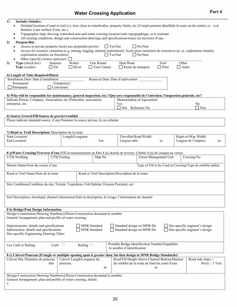
Water Crossing Application 1) Include:/Joindre:
• Detailed location of road or trail (i.e. how close to waterbodies, property limits, etc.)/l’empl.acement détailléde la route ou du sentier, (c. –à-d. distance à une surface d’eau, etc.)
• Topographic map, showing watershed area and water crossing location/carte topographique, et le tournant • All existing conditions, design and construction drawings and specifications/toutes les traverses d’eau.
2) Purpose/But • Access to private property/Accès aux propriétés privées Yes/Oui No/Non • Access for resource extraction (e.g. mining, logging, mineral exploration)/ Accès pour extraction de ressources (p. ex. exploration minière,
exploitation minière ou forestière) Yes/Oui No/Non • Other (specify)/Autres (préciser) __________________________________________________________________________
3) Type (check box) Summer Winter Year Round Haul Road Trail Other Type (cocher) Été Hiver Tout l’année Route de transport Piste Autre 4) Length of Time Required/Durée Installation Date/ Date d’installation ______________ Removal Date/ Date d’enlévement _____________ Permanent/ Termporary/ Permanent Cout terme 5) Who will be responsible for maintenance, general inspection, etc.?/Qui sera responsable de l’entretien, l’inspection générale, etc? Indicate Person, Company, Association, etc./Particulier, association, entreprise, etc.
Memorandum of Agreement/ Yes No
Oui Reference No. Non 6) Source Gravel/Fill/Source de gravier/remblai Please indicate intended source, if any/Nommer la source prévue, le cas échéant 7) Road or Trail Description/ Description de la route Start Location/ End Location/
Length/Longueur km
Travelled Road Width/ Largeur utile m
Right-of-Way Width/ Largeur de l’emprise m
8 a)Water Crossing/Traverse d’eau (Fill in measurements on Part 4 (a) sketch on reverse/ à Partie 4 (a) de croquis au verso) UTM Northing
UTM Easting Map No. Forest Management Unit Crossing No.
Stream Name/Nom du course d’eau Type of Fill to be Used at Crossing/Type de remblai utilisé Road or Trail Name/Nom de la route
Road or Trail Description/Description de la route:
Site Conditions/Condition du site; Terrain, Vegetation, Fish Habitat, Erosion Potential, etc/
Soil Description; shoreland, channel information/Salir la description, le rivage, l’information de channel
8 b) Bridge/Pont Design Information Design-Construction Drawing Number(s)/Desin-Construction dessinant le nombre General Arrangement; plan and profile of water crossing: Superstructure: details and specifications MNR Standard Standard design on MNR file Site-specific engineer’s design Substructure: details and specifications MNR Standard Standard design on MNR file Site-specific engineer’s design Site-specific Engineering Drawing Titles:
Use Curb or Railing Curb Railing Portable Bridge Identification Number/Enjambler le nombre d’identification
8 c) Culvert/Ponceau (If single or multiple opening span is greater than 3m then design to MNR Bridge Standards)/ Culvert Dia./Diamètre du ponceau mm
Culvert Length/Longueur du ponceau m
Road Fill Height Above Channel Bottom/Hauteur du remblai de la route au fond du cours d’eau m
Road side slope = Horiz. / 1 Vert.
Design-Construction Drawing Number(s)/Desin-Construction dessinant le nombre General Arrangement; plan and profile of water crossing, details #
Part 4

21
EXISTING CONDITIONS
PROPOSED BRIDGE DIMENSIONS TYPE A TYPE B TYPE C or SEE ATTACHED SKETCH
CROSSING # BRIDGE SITE DATA FORM
A = Floodplain Width = _______________ Measured Stream Velocity = ____________
B = Bankful Width = ___________ Date Velocity Measured on _____________
C = Channel Width = __________ Watershed:
D(l) = Depth at 25% of Channel = __________ Drainage Area = ________________
D(c) = Depth at 50% of Channel = __________ Lake Area = ___________________
D(r) = Depth at 75% of Channel = ____________ Wetlands Area = _______________
E = Depth of Bankful Flow = ___________ Slope = ______________________
F = Depth of Floodplain = ___________ 25-year Design Flow (Q25) = ____________
G = Bridge length = _____________ Estimating Waterway Capacity
H = Clear opening width = ________ Bridge opening area below 0.5 m freeboard = sq m
I = Freeboard (min. 0.5 m) = ________ Manning’s equation
J = Flood rise = ________________ Manning’s ‘n’ = _______________
K = Fill height = ________________ Channel Slope = _______________ m/m
L = Left slope length = ___________ Calculated velocity = ___________m/sec
M = Left slope rise = _____________ Measured flow velocity = ___________ m/sec
N = Right slope length = _________ Assume 1 m / sec flow velocity
O = Right slope rise = ___________ Waterway capacity (Bridge opening area x velocity)
P = Crib width = _______________ = _____________m3/sec (must be > Q25)
Note: 1. This form is to be kept on owner’s file and submitted to MNR on request.
2. Company’s form recording similar information may be used to replace this form.

22
Sketches for Bridge Site Data Form TYPE A - Bridge supported on sill timber outside 2:1 slope line
TYPE B – Bridge supported by crib abutments outside 2:1 slope line
TYPE C – Bridge supported by crib abutments with crib bottom level with or below streambed
23
Appendix B
Approval Process for CFSA Authorized Bridges

24
Appendix B - Approval Process for CFSA Authorized Bridges
Part 1 AWS REVIEW OF ENVIRONMENTAL ASPECTS
Information provided for AWS Approval Approval based on information provided by SFL for work to be carried out under AWS including: 1. Road locations (Operations Map and AWS Table 4) 2. Water Crossing Location (Operations Map and AWS Table 5) 3. Decommissioning requirements (AWS Table 4 and 5) 4. Fish Risk Evaluation (Appendix 1)
i. Associated special conditions ii. Proposed structure type (i.e. for portable bridges, must be listed in SFL bridge inventory included in AWS) iii. For High risk crossings may also include recommendations arising from site visit iv. DFO advice (i.e. if applicable) v. Site specific sediment control plan requirements (i.e. if applicable) vi. Watershed Hydrology Calculation
5. Mandatory standards to control erosion and sediments (e.g. Tool Kits referenced in AWS or FMP)
Authorized Under CFSA No
Yes
Work Permit Application Non CFSA Owners, Private land,
Provincial Parks, Conservation Areas
Authorized Under PLA
MNR Engineer Review Reviews bridge information submitted. Deals with the bridge owner to sort out deviations from the MNR Crown Land Bridge Management Guidelines. Notify the District when review is complete.
Part 2: PRE-INSTALLATION REVIEW OF STRUCTURAL ASPECTS FOLLOWING AWS APPROVAL
For bridges, will the structure be in place more than 7 years?
For culverts, is any span > 3 m? A site specific design is to be prepared by a professional engineer. The design engineer completes Assurance Form confirming compliance with MNR Crown Land Bridge Management Guidelines.
Yes
No
Temporary Bridge with a span < 12.2 m (40’)? Permanent Bridge designed by the owner’s engineer?
Yes
a) a standard bridge design drawing on file with MNR is used for the primary superstructure components. b) a bridge identification number for the superstructure is on record. c) a standard abutment design drawing by MNR or by the bridge owner’s professional engineer is to be used. On bridges used outside the frozen winter season, the abutment is to be founded behind an imaginary 2H:1V line sloping up from the streambed showing no evidence of scouring or erosion. d) a pre-construction site visit is carried out by a competent person and a record is kept on file describing the water width, water depth, high water mark, flow velocity, substrate soils, foundation soils, foundation suitability, bank height and site preparation work needed. e) the bridge clearly spans the normal water width.
A bridge project can be proposed without a site specific engineer’s design provided: a) an experienced and competent project co-ordinator is responsible for the construction. b) standard bridge designs are used without modification. c) the bridge spans less than 24.4 m (80’). d) a record is kept on file and submitted to MNR describing the water width, water depth, high water mark, flow velocity, substrate soils, foundation soils, foundation suitability, bank height and site preparation work needed. e) The bridge clearly spans the normal water width.
Yes
The owner’s representative completes Bridge Design Record Form confirming compliance with MNR Crown Land Bridge Management
Guidelines.
The competent project designer completes Bridge Design Record Form confirming compliance with MNR Crown Land Bridge Management Guidelines.
Yes
Yes
Yes
No MNR Engineer Review required
A site-specific design can be made by the owner’s engineer, subject to the following standards: a) changes can be made to the MNR standard drawings by the owner’s engineer for bridges less than 24.4 m (80’) span provided the modifications do not decrease the load carrying capacity. b) for bridges other than the MNR standard drawings, the primary superstructure component design requires the seals of two professional engineers. c) the owner’s engineer can design the sub-structure for any bridge length, with one engineer seal. d) the engineer’s drawing indicates the water width, water depth, flood level, flow velocity, substrate soils, foundation soils, foundation suitability, bank height and site preparation work needed.
The design engineer completes Bridge Design Record Form confirming
compliance with MNR Crown Land Bridge Management Guidelines.
Yes
MNR District Review For crossings approved under Part 1 above (AWS), District receives the Bridge Design
Record Form and MNR Regional Engineer review (when required).
Authorization to install / construct the bridge.
Yes
No
No
No

25
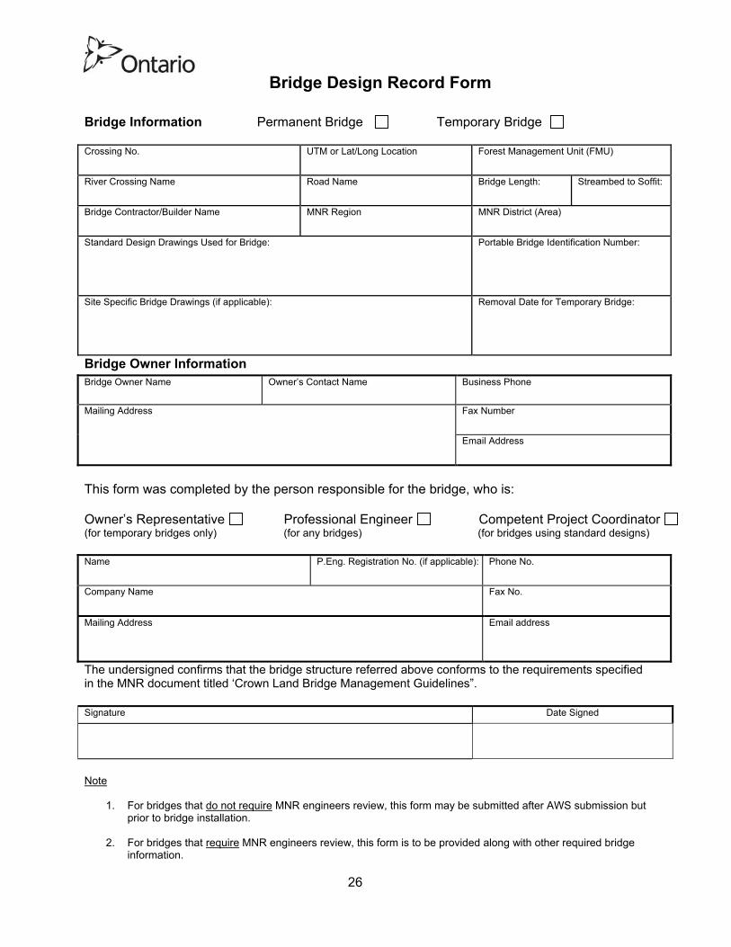
APPENDIX C
BRIDGE DESIGN RECORD FORM
26
Bridge Design Record Form Bridge Information Permanent Bridge Temporary Bridge Crossing No. UTM or Lat/Long Location Forest Management Unit (FMU)
River Crossing Name
Road Name Bridge Length: Streambed to Soffit:
Bridge Contractor/Builder Name
MNR Region MNR District (Area)
Standard Design Drawings Used for Bridge:
Portable Bridge Identification Number:
Site Specific Bridge Drawings (if applicable):
Removal Date for Temporary Bridge:
Bridge Owner Information Bridge Owner Name Owner’s Contact Name Business Phone
Fax Number
Mailing Address Email Address
This form was completed by the person responsible for the bridge, who is: Owner’s Representative Professional Engineer Competent Project Coordinator (for temporary bridges only) (for any bridges) (for bridges using standard designs) Name P.Eng. Registration No. (if applicable): Phone No.
Company Name
Fax No.
Mailing Address
Email address
The undersigned confirms that the bridge structure referred above conforms to the requirements specified in the MNR document titled ‘Crown Land Bridge Management Guidelines”. Signature Date Signed
Note
1. For bridges that do not require MNR engineers review, this form may be submitted after AWS submission but prior to bridge installation.
2. For bridges that require MNR engineers review, this form is to be provided along with other required bridge information.
27
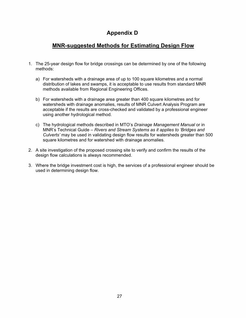
Appendix D
MNR-suggested Methods for Estimating Design Flow
1. The 25-year design flow for bridge crossings can be determined by one of the following
methods:
a) For watersheds with a drainage area of up to 100 square kilometres and a normal distribution of lakes and swamps, it is acceptable to use results from standard MNR methods available from Regional Engineering Offices.
b) For watersheds with a drainage area greater than 400 square kilometres and for watersheds with drainage anomalies, results of MNR Culvert Analysis Program are acceptable if the results are cross-checked and validated by a professional engineer using another hydrological method.
c) The hydrological methods described in MTO’s Drainage Management Manual or in MNR’s Technical Guide – Rivers and Stream Systems as it applies to ‘Bridges and Culverts’ may be used in validating design flow results for watersheds greater than 500 square kilometres and for watershed with drainage anomalies.
2. A site investigation of the proposed crossing site to verify and confirm the results of the
design flow calculations is always recommended. 3. Where the bridge investment cost is high, the services of a professional engineer should be
used in determining design flow.

28
APPENDIX E
BRIDGE INSPECTION GUIDELINES
There are normally two levels of inspection. The first level of inspection can be undertaken by a competent person designated by the bridge owner to observe indications of change to the bridge components since the last inspection. This document provides guidance for such an inspection by the competent person. Any deficiencies detected in the primary superstructure components must be discussed with an engineer who will decide if a more detailed inspection is required or not. An evaluation, subsequent to a more detailed inspection by an engineer, may be conducted to determine the overall condition and to assess the structural capacity of the structure. Most bridge data does not change from year to year. Details such as span, clearance, material types, width, etc., are recorded once and should not have to be re-checked. However, the performance and condition of the various bridge components should be inspected and recorded according to the schedule specified in the Bridge Standards document. During the inspection, the competent person should look for obvious changes of the bridge components since the last inspection. Inspection by Competent Person The first inspection of the bridge will produce geometric data and a starting list of defects, which can then be monitored and observed in the subsequent reviews. Future inspections are intended to observe obvious changes in bridge conditions. A suggested format for the inspection report in the form of inspection checklist is provided. The bridge owner shall review the inspection reports and any deficiencies or irregularities are to be followed up with appropriate actions. These may include discussions with and/or inspection by a professional engineer, file notation and further monitoring, or correction of the deficiency. Any action taken to correct deficiencies is to be recorded on file, including any engineering reports. At this stage, when the inspection is considered as complete, the inspection report should be filed away with the rest of the individual bridge record. Bridge Inspection Checklist A bridge structure can be divided into various components and the condition of each is normally examined individually. The inspector should assess each component for two criteria: what is the condition of the material of each component; and, how well is each component performing the job it is expected to do. This is done by visual observation using a checklist to ensure all items are reviewed. The inspector should have all previous data about the bridge condition on hand at the time of the inspection. Each component should be examined and a comparison made between its observed performance and material condition to that reported in the last inspection. At least two photographs should be taken at every inspection and more if changes are detected. Items suggested for examination during the inspection are listed below.

29
Bridge Opening These items should be checked to confirm the water opening is adequate to pass flood flows without endangering the structure and to ensure adequate environmental protection measures are in place. High Water Marks - Look for high water marks and signs of bridge over topping. If this has occurred, record the high water mark relative to the deck. Erosion - Erosion of fill slopes, ditch lines, or river banks that could cause sediment to enter the water or that could undermine the bridge substructure should be noted and corrected. Clear Waterways - Channel blockages or debris in the water opening should be noted. Bridge Substructure (abutments, piers, piles & foundation) Performance defects in the foundations, abutments, or piers relate to their ability to support the bridge components above them. The following should be checked and any change noted: Vertical Walls - Out of plumb walls, leaning, or rotation of bearing surfaces. Loss of Fill - Loss of fill material through abutments and wingwalls. Settlement - Abrupt drop or kinks in the bridge deck profile that could indicate settlement. Pile Support - Pile settlement, pile caps should bear on all piles. Undermining - Scour of support material and undermining of the abutments or piers. Integrity - Failure of a crib or pile bent to act as a solid unit due to distortion or members breaking away. Timber Condition – the condition of timber such as such as rot, cracking or crushing. Bridge Stringers Performance defects relate to the ability of the stringers to support the dead loads and live loads between solid supports. During the inspection, the following should be checked: Stringer Failure - Look for failed stringers that have fallen out of position or overstressing cracks at the bottom of the stringers near mid span or cracks of significance at the end areas of stringers Integrity - Check the integrity of the structural components. Are the bolts tight, do all the stringers make good contact with the support surfaces, any corrosion or cracking of steel, etc.?

30
Bridge Deck A bridge deck inspection should look for: Loose Decking - Loose or missing parts in wood decks. Nails - Nails protruding out of wood decks. Support Deck - Decay/rot in the support deck that could lead to a wheel breaking through between the stringers. Record any holes in the deck. Gap on Deck - material from the deck continuously entering the water body. Bridge Approaches The surface condition of the access road leading to a bridge site will give an indication of the traffic using it. Observations of the following should be recorded: Signs - The presence or absence of signs (six of them altogether) relating to the bridge should be recorded. Road Use - Any change in road use, for example, from active heavy truck hauling to light recreational traffic Traffic Volume - Traffic volumes and frequency of usage.
31
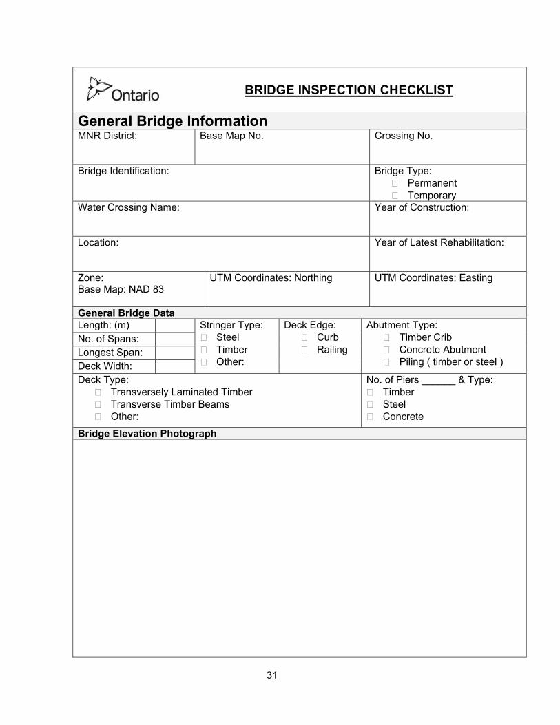
BRIDGE INSPECTION CHECKLIST
General Bridge Information MNR District: Base Map No. Crossing No.
Bridge Identification:
Bridge Type: Permanent Temporary
Water Crossing Name:
Year of Construction:
Location:
Year of Latest Rehabilitation:
Zone: Base Map: NAD 83
UTM Coordinates: Northing UTM Coordinates: Easting
General Bridge Data Length: (m) No. of Spans: Longest Span: Deck Width:
Stringer Type: Steel Timber Other:
Deck Edge: Curb Railing
Abutment Type: Timber Crib Concrete Abutment Piling ( timber or steel )
Deck Type: Transversely Laminated Timber Transverse Timber Beams Other:
No. of Piers ______ & Type: Timber Steel Concrete
Bridge Elevation Photograph
32
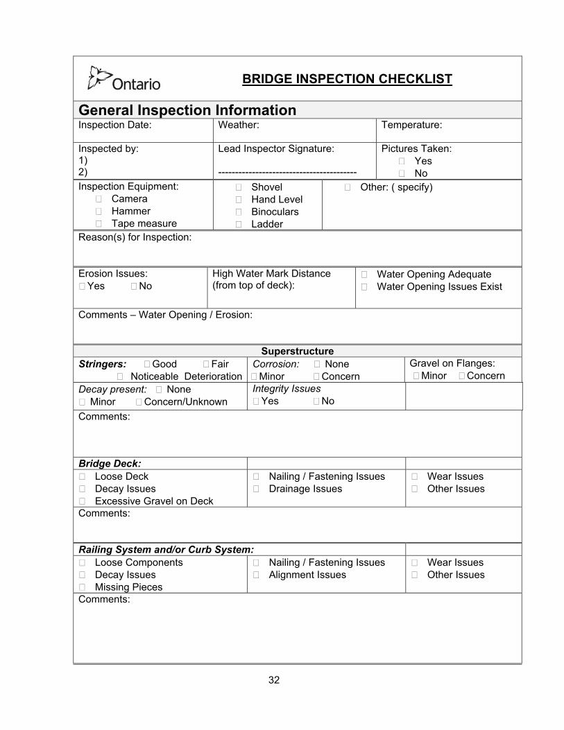
BRIDGE INSPECTION CHECKLIST
General Inspection Information Inspection Date: Weather:
Temperature:
Inspected by: 1) 2)
Lead Inspector Signature: -----------------------------------------
Pictures Taken: Yes No
Inspection Equipment: Camera Hammer Tape measure
Shovel Hand Level Binoculars Ladder
Other: ( specify)
Reason(s) for Inspection: Erosion Issues:
Yes No High Water Mark Distance (from top of deck):
Water Opening Adequate Water Opening Issues Exist
Comments – Water Opening / Erosion:
Superstructure Stringers: Good Fair
Noticeable DeteriorationCorrosion: None Minor Concern
Gravel on Flanges: Minor Concern
Decay present: None Minor Concern/Unknown
Integrity Issues Yes No
Comments: Bridge Deck:
Loose Deck Decay Issues Excessive Gravel on Deck
Nailing / Fastening Issues Drainage Issues
Wear Issues Other Issues
Comments: Railing System and/or Curb System:
Loose Components Decay Issues Missing Pieces
Nailing / Fastening Issues Alignment Issues
Wear Issues Other Issues
Comments:
33
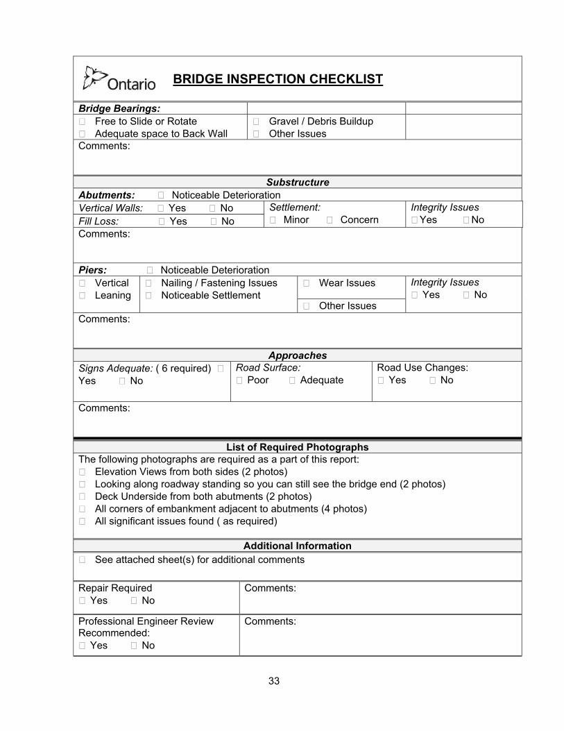
BRIDGE INSPECTION CHECKLIST
Bridge Bearings:
Free to Slide or Rotate Adequate space to Back Wall
Gravel / Debris Buildup Other Issues
Comments:
Substructure Abutments: Noticeable Deterioration Vertical Walls: Yes No Fill Loss: Yes No
Settlement: Minor Concern
Integrity Issues Yes No
Comments: Piers: Noticeable Deterioration
Wear Issues Vertical Leaning
Nailing / Fastening Issues Noticeable Settlement
Other Issues
Integrity Issues Yes No
Comments:
Approaches Signs Adequate: ( 6 required) Yes No
Road Surface: Poor Adequate
Road Use Changes: Yes No
Comments:
List of Required Photographs The following photographs are required as a part of this report:
Elevation Views from both sides (2 photos) Looking along roadway standing so you can still see the bridge end (2 photos) Deck Underside from both abutments (2 photos) All corners of embankment adjacent to abutments (4 photos) All significant issues found ( as required)
Additional Information
See attached sheet(s) for additional comments
Repair Required Yes No
Comments:
Professional Engineer Review Recommended:
Yes No
Comments:

34
Appendix F
Information for Bridge File Record
A. For bridges built on or after April 1, 2008, each bridge file is to contain the following documents:
Design information must include: 1. the pre-construction inspection report,
2. site-specific bridge design drawings, if any were prepared
3. reference to any standard bridge designs used in the project,
4. the name of the bridge designer,
5. any engineering reports associated with the project,
6. the documents submitted for bridge approval and MNR’s conditions of bridge
approval. Material purchase information should include: 7. lists of construction materials,
8. supplier names,
9. supplier certificates verifying the actual steel or timber grades and pickup or delivery
dates. Construction information must include: 10. the name of the bridge builder,
11. the dates of construction,
12. the post-construction inspection report by a professional engineer (for spans greater
than 24.4 m) or a competent person (for spans 24.4 m or less) or an Engineer’s as-built drawing (> 24.4 m spans).
Bridge inspections must include: 13. all inspection reports by competent persons,
14. all professional engineer’s reports, and
15. all reports documenting the bridge owner’s action in response to inspections.
35
B. For bridges built before April 1, 2008, every reasonable effort must be made to ensure that the bridge file is as complete as possible. Each bridge file should contain the following documents:
1. the physical geometry of the bridge in plan, profile, and cross-section,
2. a sketch of the bridge cross-section,
3. the actual dimensions (measurements) of primary superstructure components,
4. photographs of the bridge showing its profile, deck, stringers, substructure and any
deficiencies,
5. a confirmation that the required signage is present, with verifying photographs,
6. all inspection reports by competent persons, any engineer’s reports and all reports documenting the bridge owner’s action in response to inspections.
36
Appendix G
MNR Standard Design Drawings
1. MNR Standard Drawings Bridges on Crown Land (a total of 6 drawings in imperial unit)
2. MNR Standard Drawings Bridges on Crown Land (a total of 6 drawings in metric unit)
3. MNR Portable 2 stringer Bridge Drawings (a total of 5 drawings in imperial unit)
4. 16 ft. x 8 ft. Timber Crib Substructure for bridge deck not wider than 14 ft. 5. 16 ft. x 4 ft. Timber Crib Shallow Substructure for bridge deck not wider than 14 ft.
6. Sill log/square timber support for temporary bridges