crp lined pipe brochure
TRANSCRIPT
Lined Pipe and Fittings PDS LPF/UK/01 Iss. 14 This information is for general guidance only, no warranty is given for it’s accuracy and CRP reserve the right to change specifications without notice © CRP
Page Page 11 www.crp.co.uk
PTFE Lined Piping and Fittings Full Product Catalogue
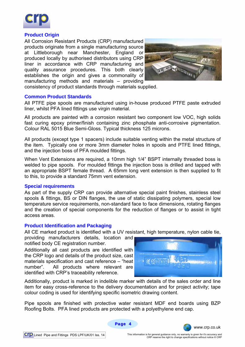
Van Stone Pipe Spool Manufacture
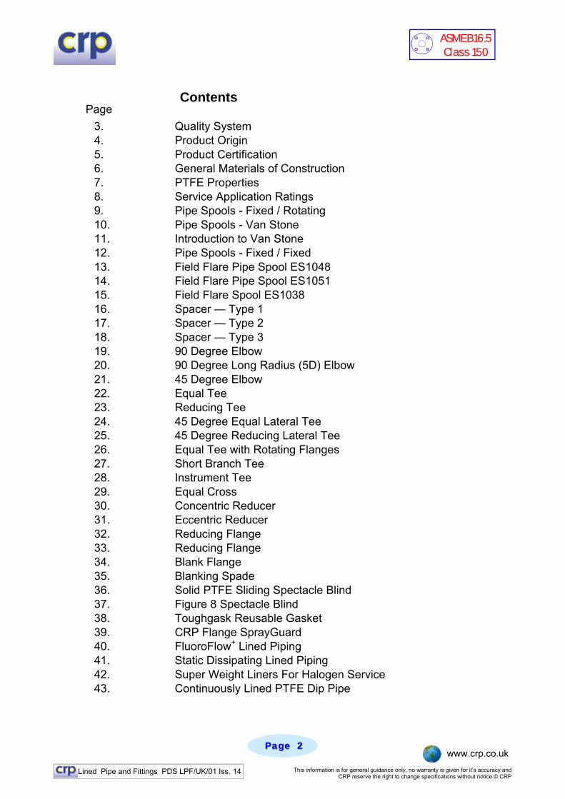
Paste Extrusion PTFE Facility Automated PFA Moulding
Lined Pipe and Fittings PDS LPF/UK/01 Iss. 14 This information is for general guidance only, no warranty is given for it’s accuracy and CRP reserve the right to change specifications without notice © CRP
Page Page 22 www.crp.co.uk
Contents
3. Quality System 4. Product Origin 5. Product Certification 6. General Materials of Construction 7. PTFE Properties 8. Service Application Ratings 9. Pipe Spools - Fixed / Rotating 10. Pipe Spools - Van Stone 11. Introduction to Van Stone 12. Pipe Spools - Fixed / Fixed 13. Field Flare Pipe Spool ES1048 14. Field Flare Pipe Spool ES1051 15. Field Flare Spool ES1038 16. Spacer — Type 1 17. Spacer — Type 2 18. Spacer — Type 3 19. 90 Degree Elbow 20. 90 Degree Long Radius (5D) Elbow 21. 45 Degree Elbow 22. Equal Tee 23. Reducing Tee 24. 45 Degree Equal Lateral Tee 25. 45 Degree Reducing Lateral Tee 26. Equal Tee with Rotating Flanges 27. Short Branch Tee 28. Instrument Tee 29. Equal Cross 30. Concentric Reducer 31. Eccentric Reducer 32. Reducing Flange 33. Reducing Flange 34. Blank Flange 35. Blanking Spade 36. Solid PTFE Sliding Spectacle Blind 37. Figure 8 Spectacle Blind 38. Toughgask Reusable Gasket 39. CRP Flange SprayGuard 40. FluoroFlow+ Lined Piping 41. Static Dissipating Lined Piping 42. Super Weight Liners For Halogen Service 43. Continuously Lined PTFE Dip Pipe
Page
ASME B16.5 Class 150

Lined Pipe and Fittings PDS LPF/UK/01 Iss. 14 This information is for general guidance only, no warranty is given for it’s accuracy and CRP reserve the right to change specifications without notice © CRP
Page Page 33 www.crp.co.uk
Quality System Corrosion Resistant Products is an ISO 9001:2000 approved company. Originally accredited to BS5750 Part 1 in 1992, CRP maintains this accreditation through a process of continuous third party surveillance with, six monthly, annual and triennial audits taking place. The company was one of the first in the UK to obtain approval to the upgraded version ISO 9001:2000. All of the company’s manufacturing and test procedures fall within this regime.
Design and Test Standards
Products are all manufactured and tested to national and international standards where applicable, with fundamental design qualification having been undertaken via the approval process required to comply with the Pressure Equipment Directive 97/23/EC.
Qualification Testing: To EDSPIP 53.01C and ASTM F423/ASTM F1545. Rating: Full vacuum to Class 150 at 200°C for sizes up to and
including 150NB. Design: ASME B16.5 Class 150 (except instrument tees, since these
are not covered by any standard). Instrument tees – in-house design, approved under Pressure Equipment Directive, and line with relevant ASME standards.
Terminations: Fixed flanges fitted off centres. Dimensions: Fitting centreline to face and face to face dimensions are in
accordance with those laid down in ASME B16.5 where relevant.
Product Traceability
All CRP manufactured Lined Pipe & Fittings are backwards traceable from the f inished component to the manufacturing tests, processes and lining materials. Each spool has one flange stamped with the reference of the liner batch used in its construction. This provides traceability back to the liner manufacture, the tests undertaken and the materials certification of the polymer. PFA moulded items likewise are stamped with a mould reference which again provide traceability back to the manufacturing and test activities and the material certification of the polymers used.
Lined Pipe and Fittings PDS LPF/UK/01 Iss. 14 This information is for general guidance only, no warranty is given for it’s accuracy and CRP reserve the right to change specifications without notice © CRP
Page Page 44 www.crp.co.uk
Product Origin All Corrosion Resistant Products (CRP) manufactured products originate from a single manufacturing source at Littleborough near Manchester, England or produced locally by authorised distributors using CRP liner in accordance with CRP manufacturing and quality assurance procedures. This both clearly establishes the origin and gives a commonality of manufacturing methods and materials – providing consistency of product standards through materials supplied.
Common Product Standards All PTFE pipe spools are manufactured using in-house produced PTFE paste extruded liner, whilst PFA lined fittings use virgin material.
All products are painted with a corrosion resistant two component low VOC, high solids fast curing epoxy primer/finish containing zinc phosphate anti-corrosive pigmentation. Colour RAL 5015 Blue Semi-Gloss. Typical thickness 125 microns.
All products (except type 1 spacers) include suitable venting within the metal structure of the item. Typically one or more 3mm diameter holes in spools and PTFE lined fittings, and the injection boss of PFA moulded fittings.
When Vent Extensions are required, a 10mm high 1/4” BSPT internally threaded boss is welded to pipe spools. For moulded fittings the injection boss is drilled and tapped with an appropriate BSPT female thread. A 65mm long vent extension is then supplied to fit to this, to provide a standard 75mm vent extension.
Special requirements As part of the supply CRP can provide alternative special paint finishes, stainless steel spools & fittings, BS or DIN flanges, the use of static dissipating polymers, special low temperature service requirements, non-standard face to face dimensions, rotating flanges and the creation of special components for the reduction of flanges or to assist in tight access areas.
Product Identification and Packaging All CE marked product is identified with a UV resistant, high temperature, nylon cable tie, providing manufacturers details, location and notified body CE registration number. Additionally all cast products are identified with the CRP logo and details of the product size, cast materials specification and cast reference – “heat number”. All products where relevant are identified with CRP’s traceability reference.
Additionally, product is marked in indelible marker with details of the sales order and line item for easy cross-reference to the delivery documentation and for project activity; tape colour coding is used for identifying specific isometric drawing content.
Pipe spools are finished with protective water resistant MDF end boards using BZP Roofing Bolts. PFA lined products are protected with a polyethylene end cap.
Lined Pipe and Fittings PDS LPF/UK/01 Iss. 14 This information is for general guidance only, no warranty is given for it’s accuracy and CRP reserve the right to change specifications without notice © CRP
Page Page 55 www.crp.co.uk
Product Certification Standard product certification comprises a certificate of compliance and test to EN10204 type 2.2, confirming that the products supplied meet the relevant specifications, that fluoropolymers meet the requirements of the FDA regulation reference 21 CFR 177.1550 and details of the product tests undergone. Project documentation – to customer specification. The following documentation can be supplied as evidence of quality control: Quality Plan, Product Drawings, Weld Procedures, Welder Qualifications, NDT Procedures, NDT Operator Qualification, Material Certification (2.2 or 3.1) and CRP Certificate of Conformance. Testing • All virgin PTFE/PFA lined products are subject to an electrostatic spark test at 25kV.
All pipe spools and certain fittings are also subject to Hydrotest at 29 bar(g) for three minutes, followed by a relaxation dwell to atmospheric pressure and a repeat.
• All spools and fittings lined in static dissipating PTFE/PFA are subject to Hydrotest
at 29 bar(g) for three minutes, followed by a relaxation dwell to atmospheric pressure and a repeat.
• All spools and fittings are visually examined, particularly the flare faces, to ensure
that there are no defects that would prevent the item sealing against adjacent items. • The mechanical properties and the specific gravity of representative samples of
PTFE liner, selected from each sinter batch, are tested PTFE and PFA Specifications
Liner Type Specification Properties
Virgin PTFE Paste Extruded ASTM D4895 Minimum Tensile Strength: 20.7 MPa Minimum Elongation at Break: 250% Specific Gravity: 2.14 – 2.18 (when tested to ASTM D792 or D1505)
Static Dissipating PTFE Paste Extruded ASTM D4895
Minimum Tensile Strength: 20.7 MPa Minimum Elongation at Break: 250% Specific Gravity: 2.14 – 2.18 (when tested to ASTM D792 or D1505) Volume Resistivity: <107 Ω.cm
Virgin PFA ASTM D3307 Minimum Tensile Strength: 26.2 MPa Minimum Elongation at Break: 300% Specific Gravity: 2.12 – 2.17 (when tested to ASTM D792 or D1505) Melt Flow Rate: 1-2.5g/10mins (when tested to ASTM D3307 at 372°C
Static Dissipating PFA ASTM D3307
Minimum Tensile Strength: 26.2 MPa Minimum Elongation at Break: 300% Specific Gravity: 2.12 – 2.17 (when tested to ASTM D792 or D1505) Melt Flow Rate: 1-2.5g/10mins (when tested to ASTM D3307 at 372°C Volume Resistivity: <107 Ω.cm
Virgin PTFE Isostatically Moulded ASTM D4894
Minimum Tensile Strength: 17.3 MPa Minimum Elongation at Break: 250% Specific Gravity: 2.14 – 2.18 (when tested to ASTM D792 or D1505)
Static Dissipating PTFE Isostatically Moulded ASTM D4894
Minimum Tensile Strength: 17.3 MPa Minimum Elongation at Break: 250% Specific Gravity: 2.14 – 2.18 (when tested to ASTM D792 or D1505) Volume Resistivity: <107 Ω.cm
Lined Pipe and Fittings PDS LPF/UK/01 Iss. 14 This information is for general guidance only, no warranty is given for it’s accuracy and CRP reserve the right to change specifications without notice © CRP
Page Page 66 www.crp.co.uk
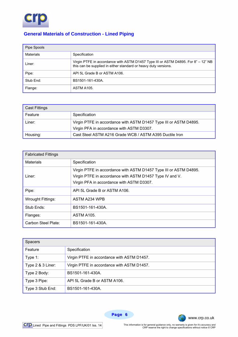
Materials Specification
Liner: Virgin PTFE in accordance with ASTM D1457 Type III or ASTM D4895. For 8” – 12” NB this can be supplied in either standard or heavy duty versions.
Pipe: API 5L Grade B or ASTM A106.
Stub End: BS1501-161-430A.
Flange: ASTM A105.
Pipe Spools
Cast Fittings
Feature Specification
Liner: Virgin PTFE in accordance with ASTM D1457 Type III or ASTM D4895. Virgin PFA in accordance with ASTM D3307.
Housing: Cast Steel ASTM A216 Grade WCB / ASTM A395 Ductile Iron
Materials Specification
Liner: Virgin PTFE in accordance with ASTM D1457 Type III or ASTM D4895. Virgin PTFE in accordance with ASTM D1457 Type IV and V. Virgin PFA in accordance with ASTM D3307.
Pipe: API 5L Grade B or ASTM A106.
Stub Ends: BS1501-161-430A.
Flanges: ASTM A105.
Fabricated Fittings
Wrought Fittings: ASTM A234 WPB
Carbon Steel Plate: BS1501-161-430A.
Spacers
Feature Specification
Type 1: Virgin PTFE in accordance with ASTM D1457.
Type 2 & 3 Liner: Virgin PTFE in accordance with ASTM D1457.
Type 2 Body: BS1501-161-430A.
Type 3 Pipe: API 5L Grade B or ASTM A106.
Type 3 Stub End: BS1501-161-430A.
General Materials of Construction - Lined Piping
Lined Pipe and Fittings PDS LPF/UK/01 Iss. 14 This information is for general guidance only, no warranty is given for it’s accuracy and CRP reserve the right to change specifications without notice © CRP
Page Page 77 www.crp.co.uk
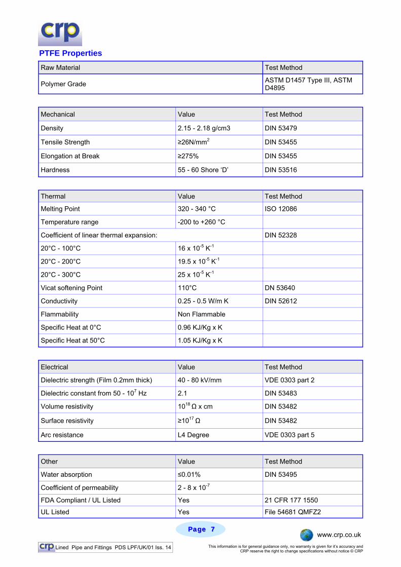
PTFE Properties Raw Material Test Method
Polymer Grade ASTM D1457 Type III, ASTM D4895
Mechanical Value Test Method
Density 2.15 - 2.18 g/cm3 DIN 53479
Tensile Strength ≥26N/mm2 DIN 53455
Elongation at Break ≥275% DIN 53455
Hardness 55 - 60 Shore ‘D’ DIN 53516
Thermal Value Test Method
Melting Point 320 - 340 °C ISO 12086
Temperature range -200 to +260 °C
Coefficient of linear thermal expansion: DIN 52328
20°C - 100°C 16 x 10-5 K-1
20°C - 200°C 19.5 x 10⁻⁵ K-1
20°C - 300°C 25 x 10-5 K-1
Vicat softening Point 110°C DN 53640
Conductivity 0.25 - 0.5 W/m K DIN 52612
Flammability Non Flammable
Specific Heat at 0°C 0.96 KJ/Kg x K
Specific Heat at 50°C 1.05 KJ/Kg x K
Electrical Value Test Method
Dielectric strength (Film 0.2mm thick) 40 - 80 kV/mm VDE 0303 part 2
Dielectric constant from 50 - 107 Hz 2.1 DIN 53483
Volume resistivity 1018 Ω x cm DIN 53482
Surface resistivity ≥1017 Ω DIN 53482
Arc resistance L4 Degree VDE 0303 part 5
Other Value Test Method
Water absorption ≤0.01% DIN 53495
Coefficient of permeability 2 - 8 x 10⁻⁷
FDA Compliant / UL Listed Yes 21 CFR 177 1550
UL Listed Yes File 54681 QMFZ2

Lined Pipe and Fittings PDS LPF/UK/01 Iss. 14 This information is for general guidance only, no warranty is given for it’s accuracy and CRP reserve the right to change specifications without notice © CRP
Page Page 88 www.crp.co.uk
ASME 300 Lined Piping Systems
ASME 150 Lined Piping Systems
Service Application Ratings The Graph below shows the pressure / temperature performance curve for CRP’s lined pipe and fittings. For products up to and including 6 in NB, they are rated for full vacuum up to 200 degrees C. Above 6 in NB please consult CRP for vacuum performance.
Lined Pipe and Fittings PDS LPF/UK/01 Iss. 14 This information is for general guidance only, no warranty is given for it’s accuracy and CRP reserve the right to change specifications without notice © CRP
Page Page 99 www.crp.co.uk
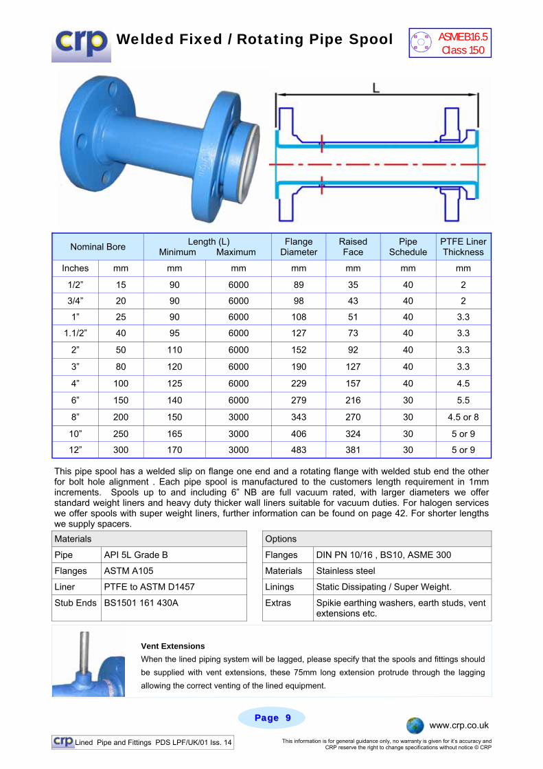
Welded Fixed / Rotating Pipe Spool
Nominal Bore Length (L) Minimum Maximum
Flange Diameter
Raised Face
Pipe Schedule
PTFE Liner Thickness
Inches mm mm mm mm mm mm mm
1/2” 15 90 6000 89 35 40 2
3/4” 20 90 6000 98 43 40 2
1” 25 90 6000 108 51 40 3.3
1.1/2” 40 95 6000 127 73 40 3.3
2” 50 110 6000 152 92 40 3.3
3” 80 120 6000 190 127 40 3.3
4” 100 125 6000 229 157 40 4.5
6” 150 140 6000 279 216 30 5.5
8” 200 150 3000 343 270 30 4.5 or 8
10” 250 165 3000 406 324 30 5 or 9
12” 300 170 3000 483 381 30 5 or 9
This pipe spool has a welded slip on flange one end and a rotating flange with welded stub end the other for bolt hole alignment . Each pipe spool is manufactured to the customers length requirement in 1mm increments. Spools up to and including 6” NB are full vacuum rated, with larger diameters we offer standard weight liners and heavy duty thicker wall liners suitable for vacuum duties. For halogen services we offer spools with super weight liners, further information can be found on page 42. For shorter lengths we supply spacers. Materials
Pipe API 5L Grade B Flanges DIN PN 10/16 , BS10, ASME 300
Flanges ASTM A105 Materials Stainless steel
Liner PTFE to ASTM D1457 Linings Static Dissipating / Super Weight.
Stub Ends BS1501 161 430A Extras Spikie earthing washers, earth studs, vent extensions etc.
Options
Vent Extensions When the lined piping system will be lagged, please specify that the spools and fittings should be supplied with vent extensions, these 75mm long extension protrude through the lagging allowing the correct venting of the lined equipment.
ASME B16.5 Class 150
Lined Pipe and Fittings PDS LPF/UK/01 Iss. 14 This information is for general guidance only, no warranty is given for it’s accuracy and CRP reserve the right to change specifications without notice © CRP
Page Page 1010 www.crp.co.uk
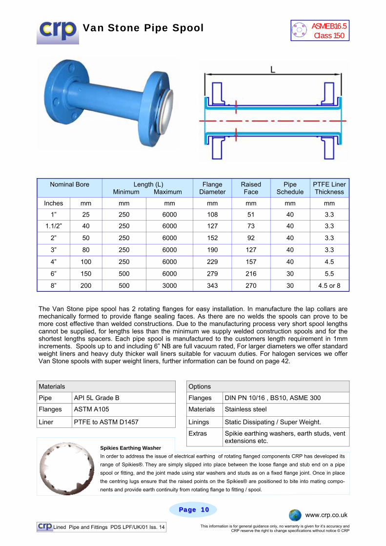
Van Stone Pipe Spool
Nominal Bore Length (L) Minimum Maximum
Flange Diameter
Raised Face
Pipe Schedule
PTFE Liner Thickness
Inches mm mm mm mm mm mm mm
1” 25 250 6000 108 51 40 3.3
1.1/2” 40 250 6000 127 73 40 3.3
2” 50 250 6000 152 92 40 3.3
3” 80 250 6000 190 127 40 3.3
4” 100 250 6000 229 157 40 4.5
6” 150 500 6000 279 216 30 5.5
8” 200 500 3000 343 270 30 4.5 or 8
The Van Stone pipe spool has 2 rotating flanges for easy installation. In manufacture the lap collars are mechanically formed to provide flange sealing faces. As there are no welds the spools can prove to be more cost effective than welded constructions. Due to the manufacturing process very short spool lengths cannot be supplied, for lengths less than the minimum we supply welded construction spools and for the shortest lengths spacers. Each pipe spool is manufactured to the customers length requirement in 1mm increments. Spools up to and including 6” NB are full vacuum rated, For larger diameters we offer standard weight liners and heavy duty thicker wall liners suitable for vacuum duties. For halogen services we offer Van Stone spools with super weight liners, further information can be found on page 42.
Materials
Pipe API 5L Grade B Flanges DIN PN 10/16 , BS10, ASME 300
Flanges ASTM A105 Materials Stainless steel
Liner PTFE to ASTM D1457 Linings Static Dissipating / Super Weight.
Extras Spikie earthing washers, earth studs, vent extensions etc.
Options
Spikies Earthing Washer In order to address the issue of electrical earthing of rotating flanged components CRP has developed its range of Spikies®. They are simply slipped into place between the loose flange and stub end on a pipe spool or fitting, and the joint made using star washers and studs as on a fixed flange joint. Once in place the centring lugs ensure that the raised points on the Spikies® are positioned to bite into mating compo-nents and provide earth continuity from rotating flange to fitting / spool.
ASME B16.5 Class 150
Lined Pipe and Fittings PDS LPF/UK/01 Iss. 14 This information is for general guidance only, no warranty is given for it’s accuracy and CRP reserve the right to change specifications without notice © CRP
Page Page 1111 www.crp.co.uk
Introduction to Van Stone Piping
CRP currently leads the UK market with our Van Stone PTFE lined piping system for both carbon steel and stainless steel piping. The process of manufacturing a pipe spool with both flanges rotating without the use of conventionally welded or screw threaded collars is known as the “Conrac” or more properly the “Van Stone” system. The process essentially forms a lap collar by spinning over the parent tube at right angles to the original tube axis. The use of the term “Conrac” which is the most widely recognised name for this process, is derived from the name of the machinery manufacturer who did much to develop the special machinery and promote the use of this flanging system. The “Conrac Corporation of California”. Product Development The development of this process was born of a need to make the manufacture of pipework cheaper, easier and technically superior. Traditionally pipework sections had been joined by fitting screwed flanges and to use a taper pipe thread, which would lock and form a seal. The steel tubes used for screw threading were very heavy and therefore expensive, the screwed flanges were also costly, prone to leakage and corrosion. The use of all welded systems was an improvement but for pre fabricated sections the quality of set up es-pecially of flange squareness and bolt hole alignment was critical. If the setting out was not done correctly it was often necessary to butcher the system to make it fit or even remake it complete. The twin needs of lower cost and ease of fabrication whilst maintaining piping integrity drove the development of the tafted lap collar. The original developments were mostly in the use of thin wall expensive exotic metals where welding was at best unreliable and often impossible. The process was then taken up for pre-fabricated sections of marine pipework where being able to fit rotating flanges to relatively light wall piping had a marked effect on speed of build, overall weight and costs.
From the very early days of PTFE lined pipe systems the use of Van Stone flanged pipe spools was adopted as the preferred method of flanging and remains the favoured choice of most international lined pipe manufacturers and users alike.
Product Testing To improve the overall quality and cost effectiveness of CRP lined pipe systems CRP purchased a Conrac machine in November 1995 and began to develop the skills and disciplines required for this type of flanging method. In the months between CRP acquiring the machine and product coming to the market place in mid 1996 a large number of tests were made. Physical Testing Sample pipe spools were manufactured and then subjected to the extended steam and cold water cycle qualification tests demanded in ASTM F423. They were also tested for vacuum and heat ageing perform-ance as well as the usual hydrostatic and electrostatic tests; all samples passed without incident. To assess the joint integrity suitably flanged spools were pressure tested to levels of 65 Bar g without any failure being observed. This pressure is substantially in excess of the 52 Bar g maximum pressure test permitted on ASME class 300 and over twice the test level for class 150. Product Advantages Accuracy Because the collar is mechanically formed, it is square and flat which helps produce very sound joints. Transition Radius Forming produces a smooth transition radius between the bore and the collar face. This gives the best sur-face for the minimisation stress in the PTFE flare. Assembly With two rotating flanges site assembly is easy enabling bolt holes to be lined up. Cost Moreover, the use of low cost rotating flanges on pipe spool reduces the need to order pipe fittings with ro-tating flanges. This in turn means that less expensive fixed flange cast fittings can be specified more often. The piping system is in its own right less expensive than a conventionally welded system. Corrosion The bolts required are much shorter giving much less shank exposed to gather dirt and get corroded.
Lined Pipe and Fittings PDS LPF/UK/01 Iss. 14 This information is for general guidance only, no warranty is given for it’s accuracy and CRP reserve the right to change specifications without notice © CRP
Page Page 1212 www.crp.co.uk
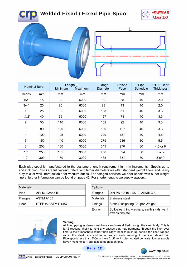
Welded Fixed / Fixed Pipe Spool
Nominal Bore Length (L) Minimum Maximum
Flange Diameter
Raised Face
Pipe Schedule
PTFE Liner Thickness
Inches mm mm mm mm mm mm mm
1/2” 15 90 6000 89 35 40 2.0
3/4” 20 90 6000 98 43 40 2.0
1” 25 90 6000 108 51 40 3.3
1.1/2” 40 95 6000 127 73 40 3.3
2” 50 110 6000 152 92 40 3.3
3” 80 120 6000 190 127 40 3.3
4” 100 125 6000 229 157 40 4.5
6” 150 140 6000 279 216 30 5.5
8” 200 150 3000 343 270 30 4.5 or 8
10” 250 165 3000 406 324 30 5 or 9
12” 300 170 3000 483 381 30 5 or 9
Each pipe spool is manufactured to the customers length requirement in 1mm increments. Spools up to and including 6” NB are full vacuum rated, with larger diameters we offer standard weight liners and heavy duty thicker wall liners suitable for vacuum duties. For halogen services we offer spools with super weight liners, further information can be found on page 42. For shorter lengths we supply spacers.
Venting All lined piping systems must have vent holes drilled through the steel body. This is for 2 reasons, firstly to vent any gasses that may permeate through the liner over time to the atmosphere rather than allow them to build up behind the liner trapped within the steel pipe and to act as an early warning if the liner should fail. Pipe spools less than 500mm have 2 off vent holes located centrally, longer spools have 4 vent holes 1 pair at located at each end.
Materials
Pipe API 5L Grade B Flanges DIN PN 10/16 , BS10, ASME 300
Flanges ASTM A105 Materials Stainless steel
Liner PTFE to ASTM D1457 Linings Static Dissipating / Super Weight.
Extras Spikie earthing washers, earth studs, vent extensions etc.
Options
ASME B16.5 Class 150
Lined Pipe and Fittings PDS LPF/UK/01 Iss. 14 This information is for general guidance only, no warranty is given for it’s accuracy and CRP reserve the right to change specifications without notice © CRP
Page Page 1313 www.crp.co.uk
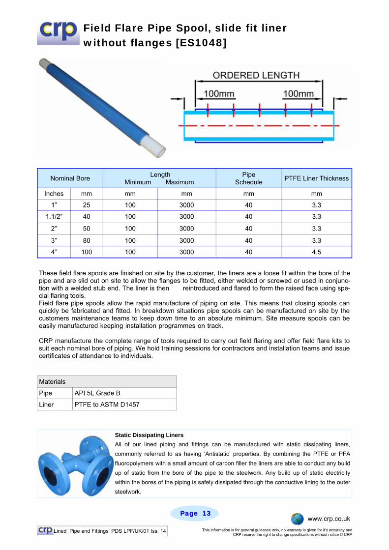
Field Flare Pipe Spool, slide fit liner without flanges [ES1048]
Nominal Bore Length Minimum Maximum
Pipe Schedule PTFE Liner Thickness
Inches mm mm mm mm mm
1” 25 100 3000 40 3.3
1.1/2” 40 100 3000 40 3.3
2” 50 100 3000 40 3.3
3” 80 100 3000 40 3.3
4” 100 100 3000 40 4.5
These field flare spools are finished on site by the customer, the liners are a loose fit within the bore of the pipe and are slid out on site to allow the flanges to be fitted, either welded or screwed or used in conjunc-tion with a welded stub end. The liner is then reintroduced and flared to form the raised face using spe-cial flaring tools. Field flare pipe spools allow the rapid manufacture of piping on site. This means that closing spools can quickly be fabricated and fitted. In breakdown situations pipe spools can be manufactured on site by the customers maintenance teams to keep down time to an absolute minimum. Site measure spools can be easily manufactured keeping installation programmes on track. . CRP manufacture the complete range of tools required to carry out field flaring and offer field flare kits to suit each nominal bore of piping. We hold training sessions for contractors and installation teams and issue certificates of attendance to individuals.
Static Dissipating Liners All of our lined piping and fittings can be manufactured with static dissipating liners, commonly referred to as having ‘Antistatic’ properties. By combining the PTFE or PFA fluoropolymers with a small amount of carbon filler the liners are able to conduct any build up of static from the bore of the pipe to the steelwork. Any build up of static electricity within the bores of the piping is safely dissipated through the conductive lining to the outer steelwork.
Materials
Pipe API 5L Grade B
Liner PTFE to ASTM D1457
Lined Pipe and Fittings PDS LPF/UK/01 Iss. 14 This information is for general guidance only, no warranty is given for it’s accuracy and CRP reserve the right to change specifications without notice © CRP
Page Page 1414 www.crp.co.uk
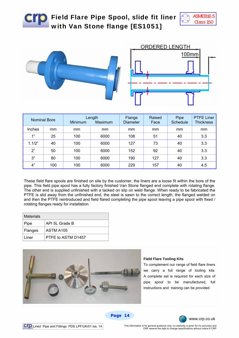
Field Flare Pipe Spool, slide fit liner with Van Stone flange [ES1051]
These field flare spools are finished on site by the customer, the liners are a loose fit within the bore of the pipe. This field pipe spool has a fully factory finished Van Stone flanged end complete with rotating flange. The other end is supplied unfinished with a tacked on slip on weld flange. When ready to be fabricated the PTFE is slid away from the unfinished end, the steel is sawn to the correct length, the flanged welded on and then the PTFE reintroduced and field flared completing the pipe spool leaving a pipe spool with fixed / rotating flanges ready for installation.
Field Flare Tooling Kits To complement our range of field flare liners we carry a full range of tooling kits. A complete set is required for each size of pipe spool to be manufactured, full instructions and training can be provided.
Nominal Bore Length Minimum Maximum
Flange Diameter
Raised Face
Pipe Schedule
PTFE Liner Thickness
Inches mm mm mm mm mm mm mm
1” 25 100 6000 108 51 40 3.3
1.1/2” 40 100 6000 127 73 40 3.3
2” 50 100 6000 152 92 40 3.3
3” 80 100 6000 190 127 40 3.3
4” 100 100 6000 229 157 40 4.5
Materials
Pipe API 5L Grade B
Flanges ASTM A105
Liner PTFE to ASTM D1457
ASME B16.5 Class 150
Lined Pipe and Fittings PDS LPF/UK/01 Iss. 14 This information is for general guidance only, no warranty is given for it’s accuracy and CRP reserve the right to change specifications without notice © CRP
Page Page 1515 www.crp.co.uk
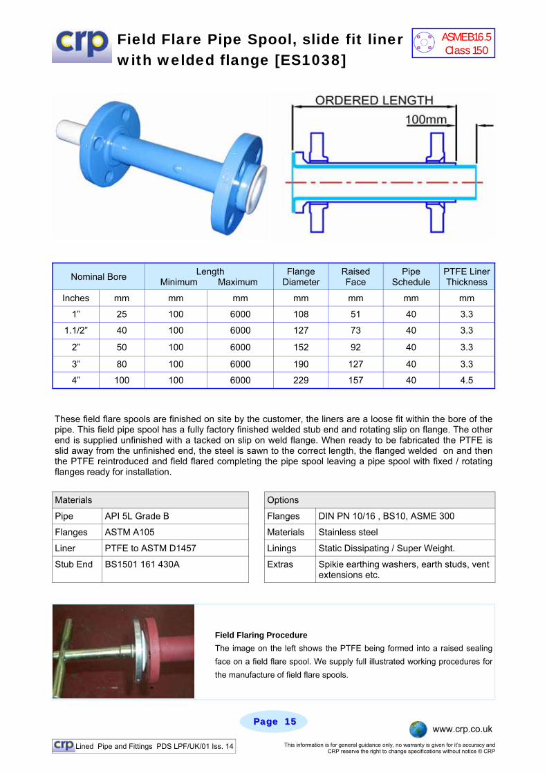
Field Flare Pipe Spool, slide fit liner with welded flange [ES1038]
These field flare spools are finished on site by the customer, the liners are a loose fit within the bore of the pipe. This field pipe spool has a fully factory finished welded stub end and rotating slip on flange. The other end is supplied unfinished with a tacked on slip on weld flange. When ready to be fabricated the PTFE is slid away from the unfinished end, the steel is sawn to the correct length, the flanged welded on and then the PTFE reintroduced and field flared completing the pipe spool leaving a pipe spool with fixed / rotating flanges ready for installation.
Field Flaring Procedure The image on the left shows the PTFE being formed into a raised sealing face on a field flare spool. We supply full illustrated working procedures for the manufacture of field flare spools.
Nominal Bore Length Minimum Maximum
Flange Diameter
Raised Face
Pipe Schedule
PTFE Liner Thickness
Inches mm mm mm mm mm mm mm
1” 25 100 6000 108 51 40 3.3
1.1/2” 40 100 6000 127 73 40 3.3
2” 50 100 6000 152 92 40 3.3
3” 80 100 6000 190 127 40 3.3
4” 100 100 6000 229 157 40 4.5
Materials
Pipe API 5L Grade B Flanges DIN PN 10/16 , BS10, ASME 300
Flanges ASTM A105 Materials Stainless steel
Liner PTFE to ASTM D1457 Linings Static Dissipating / Super Weight.
Stub End BS1501 161 430A Extras Spikie earthing washers, earth studs, vent extensions etc.
Options
ASME B16.5 Class 150
Lined Pipe and Fittings PDS LPF/UK/01 Iss. 14 This information is for general guidance only, no warranty is given for it’s accuracy and CRP reserve the right to change specifications without notice © CRP
Page Page 1616 www.crp.co.uk
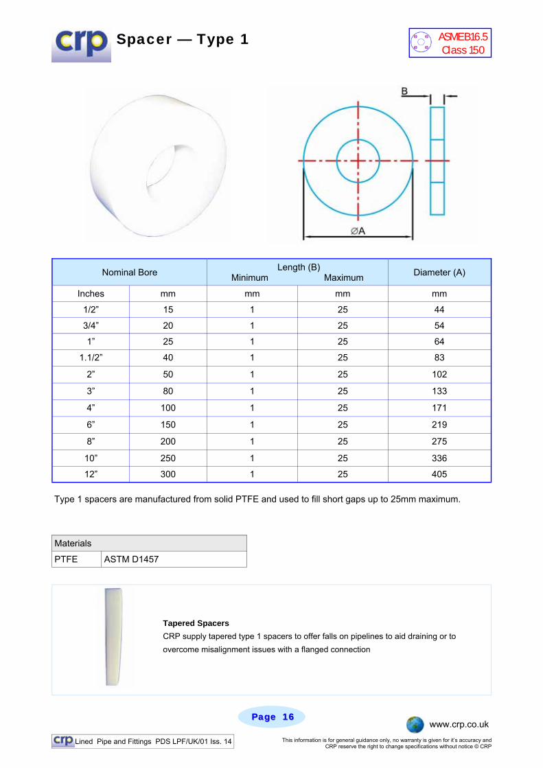
Spacer — Type 1
Type 1 spacers are manufactured from solid PTFE and used to fill short gaps up to 25mm maximum.
Tapered Spacers CRP supply tapered type 1 spacers to offer falls on pipelines to aid draining or to overcome misalignment issues with a flanged connection
Materials
PTFE ASTM D1457
Nominal Bore Length (B) Minimum Maximum Diameter (A)
Inches mm mm mm mm
1/2” 15 1 25 44
3/4” 20 1 25 54
1” 25 1 25 64
1.1/2” 40 1 25 83
2” 50 1 25 102
3” 80 1 25 133
4” 100 1 25 171
6” 150 1 25 219
8” 200 1 25 275
10” 250 1 25 336
12” 300 1 25 405
ASME B16.5 Class 150
Lined Pipe and Fittings PDS LPF/UK/01 Iss. 14 This information is for general guidance only, no warranty is given for it’s accuracy and CRP reserve the right to change specifications without notice © CRP
Page Page 1717 www.crp.co.uk
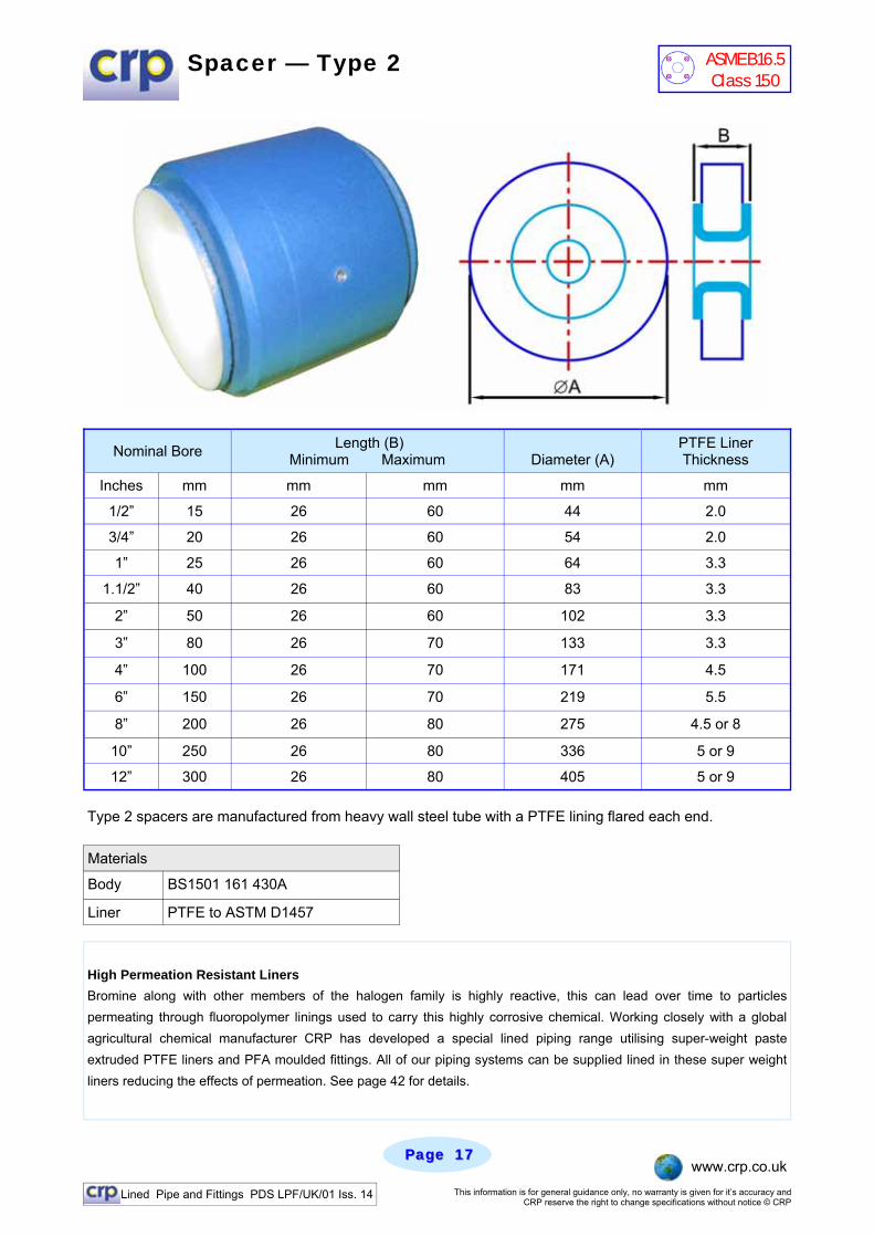
Spacer — Type 2
Type 2 spacers are manufactured from heavy wall steel tube with a PTFE lining flared each end.
High Permeation Resistant Liners Bromine along with other members of the halogen family is highly reactive, this can lead over time to particles permeating through fluoropolymer linings used to carry this highly corrosive chemical. Working closely with a global agricultural chemical manufacturer CRP has developed a special lined piping range utilising super-weight paste extruded PTFE liners and PFA moulded fittings. All of our piping systems can be supplied lined in these super weight liners reducing the effects of permeation. See page 42 for details.
Nominal Bore Length (B) Minimum Maximum
Diameter (A)
PTFE Liner Thickness
Inches mm mm mm mm mm
1/2” 15 26 60 44 2.0
3/4” 20 26 60 54 2.0
1” 25 26 60 64 3.3
1.1/2” 40 26 60 83 3.3
2” 50 26 60 102 3.3
3” 80 26 70 133 3.3
4” 100 26 70 171 4.5
6” 150 26 70 219 5.5
8” 200 26 80 275 4.5 or 8
10” 250 26 80 336 5 or 9
12” 300 26 80 405 5 or 9
Materials
Body BS1501 161 430A
Liner PTFE to ASTM D1457
ASME B16.5 Class 150
Lined Pipe and Fittings PDS LPF/UK/01 Iss. 14 This information is for general guidance only, no warranty is given for it’s accuracy and CRP reserve the right to change specifications without notice © CRP
Page Page 1818 www.crp.co.uk
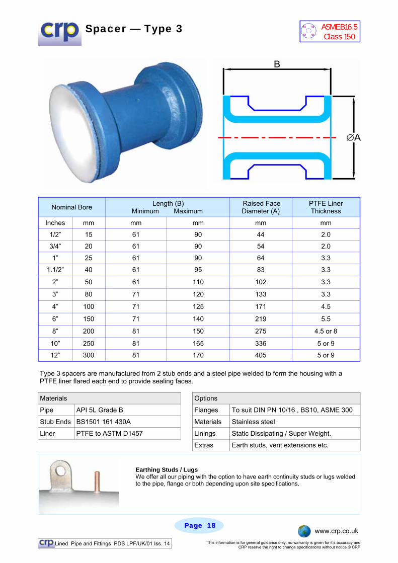
Spacer — Type 3
Type 3 spacers are manufactured from 2 stub ends and a steel pipe welded to form the housing with a PTFE liner flared each end to provide sealing faces.
Nominal Bore Length (B) Minimum Maximum
Raised Face Diameter (A)
PTFE Liner Thickness
Inches mm mm mm mm mm
1/2” 15 61 90 44 2.0
3/4” 20 61 90 54 2.0
1” 25 61 90 64 3.3
1.1/2” 40 61 95 83 3.3
2” 50 61 110 102 3.3
3” 80 71 120 133 3.3
4” 100 71 125 171 4.5
6” 150 71 140 219 5.5
8” 200 81 150 275 4.5 or 8
10” 250 81 165 336 5 or 9
12” 300 81 170 405 5 or 9
Materials
Pipe API 5L Grade B Flanges To suit DIN PN 10/16 , BS10, ASME 300
Stub Ends BS1501 161 430A Materials Stainless steel
Liner PTFE to ASTM D1457 Linings Static Dissipating / Super Weight.
Extras Earth studs, vent extensions etc.
Options
Earthing Studs / Lugs We offer all our piping with the option to have earth continuity studs or lugs welded to the pipe, flange or both depending upon site specifications.
ASME B16.5 Class 150

Lined Pipe and Fittings PDS LPF/UK/01 Iss. 14 This information is for general guidance only, no warranty is given for it’s accuracy and CRP reserve the right to change specifications without notice © CRP
Page Page 1919 www.crp.co.uk
90 Degree Elbow
Materials - PFA lined Castings Specials
Casting ASTM A216 Grade WCB
Lining PFA to ASTM D3307
Materials - PTFE lined Fabrications
Pipe API 5L Grade B / ASTM A234
Flanges ASTM 105
Lining PTFE to ASTM D1457
As well as standard 45 and 90 degree elbows, CRP can supply special elbows with any angle from 1 degree up to 180 degrees which are commonly found on heat exchangers. Whilst we would encourage using standard dimensioned elbows to ASME B16.5 dimensions we can supply special elbows with swept bends for slurry duty or to overcome installation problems etc. For elbows with angles less than 45 degrees the centre-line to face dimension adopted would be the same as 45 degree elbows, For elbows with angles above 45 degrees we adopt the 90 degree centre-line to face dimensions.
Nominal Bore Centre Line to Face (A)
Flange Diameter Raised Face Steel
Thickness Liner
Thickness
Inches mm mm mm mm mm mm
1/2” 15 100 89 35 3.0 2.5
3/4” 20 75 98 43 3.0 2.5
1” 25 89 108 51 4.5 4.1
1.1/2” 40 102 127 73 5.0 4.5
2” 50 114 152 92 6.0 4.7
3” 80 140 190 127 6.0 6.5
4” 100 165 229 157 6.5 9.0
6” 150 203 279 216 7.5 9.5
8” 200 229 343 270 8.0 9.5
10” 250 279 406 324 8.0 11.0
12” 300 305 483 381 8.0 11.0
180 Degree Elbow
ASME B16.5 Class 150
Lined Pipe and Fittings PDS LPF/UK/01 Iss. 14 This information is for general guidance only, no warranty is given for it’s accuracy and CRP reserve the right to change specifications without notice © CRP
Page Page 2020 www.crp.co.uk
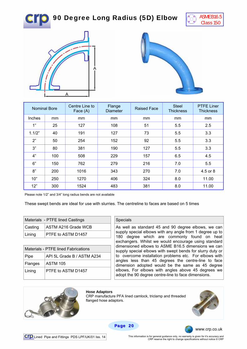
Please note 1/2” and 3/4” long radius bends are not available These swept bends are ideal for use with slurries. The centreline to faces are based on 5 times
90 Degree Long Radius (5D) Elbow
Materials - PTFE lined Castings Specials
Casting ASTM A216 Grade WCB
Lining PTFE to ASTM D1457
Materials - PTFE lined Fabrications
Pipe API 5L Grade B / ASTM A234
Flanges ASTM 105
Lining PTFE to ASTM D1457
As well as standard 45 and 90 degree elbows, we can supply special elbows with any angle from 1 degree up to 180 degree which are commonly found on heat exchangers. Whilst we would encourage using standard dimensioned elbows to ASME B16.5 dimensions we can supply special elbows with swept bends for slurry duty or to overcome installation problems etc. For elbows with angles less than 45 degrees the centre-line to face dimension adopted would be the same as 45 degree elbows, For elbows with angles above 45 degrees we adopt the 90 degree centre-line to face dimensions.
Nominal Bore Centre Line to Face (A)
Flange Diameter Raised Face Steel
Thickness PTFE Liner Thickness
Inches mm mm mm mm mm mm
1” 25 127 108 51 5.5 2.5
1.1/2” 40 191 127 73 5.5 3.3
2” 50 254 152 92 5.5 3.3
3” 80 381 190 127 5.5 3.3
4” 100 508 229 157 6.5 4.5
6” 150 762 279 216 7.0 5.5
8” 200 1016 343 270 7.0 4.5 or 8
10” 250 1270 406 324 8.0 11.00
12” 300 1524 483 381 8.0 11.00
Hose Adaptors CRP manufacture PFA lined camlock, triclamp and threaded flanged hose adaptors.
ASME B16.5 Class 150
Lined Pipe and Fittings PDS LPF/UK/01 Iss. 14 This information is for general guidance only, no warranty is given for it’s accuracy and CRP reserve the right to change specifications without notice © CRP
Page Page 2121 www.crp.co.uk
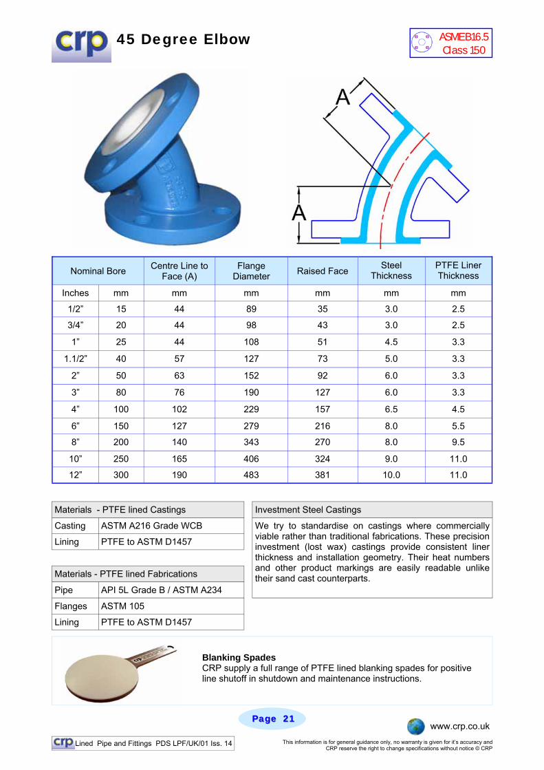
45 Degree Elbow
Materials - PTFE lined Castings Investment Steel Castings
Casting ASTM A216 Grade WCB
Lining PTFE to ASTM D1457
Materials - PTFE lined Fabrications
Pipe API 5L Grade B / ASTM A234
Flanges ASTM 105
Lining PTFE to ASTM D1457
We try to standardise on castings where commercially viable rather than traditional fabrications. These precision investment (lost wax) castings provide consistent liner thickness and installation geometry. Their heat numbers and other product markings are easily readable unlike their sand cast counterparts.
Nominal Bore Centre Line to Face (A)
Flange Diameter Raised Face Steel
Thickness PTFE Liner Thickness
Inches mm mm mm mm mm mm
1/2” 15 44 89 35 3.0 2.5
3/4” 20 44 98 43 3.0 2.5
1” 25 44 108 51 4.5 3.3
1.1/2” 40 57 127 73 5.0 3.3
2” 50 63 152 92 6.0 3.3
3” 80 76 190 127 6.0 3.3
4” 100 102 229 157 6.5 4.5
6” 150 127 279 216 8.0 5.5
8” 200 140 343 270 8.0 9.5
10” 250 165 406 324 9.0 11.0
12” 300 190 483 381 10.0 11.0
Blanking Spades CRP supply a full range of PTFE lined blanking spades for positive line shutoff in shutdown and maintenance instructions.
ASME B16.5 Class 150
Lined Pipe and Fittings PDS LPF/UK/01 Iss. 14 This information is for general guidance only, no warranty is given for it’s accuracy and CRP reserve the right to change specifications without notice © CRP
Page Page 2222 www.crp.co.uk
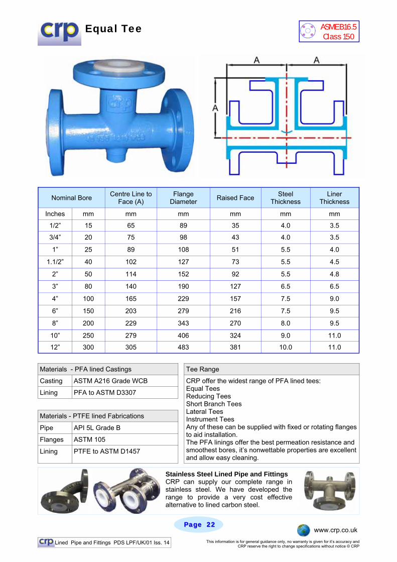
Equal Tee
Materials - PFA lined Castings Tee Range
Casting ASTM A216 Grade WCB
Lining PFA to ASTM D3307
Materials - PTFE lined Fabrications
Pipe API 5L Grade B
Flanges ASTM 105
Lining PTFE to ASTM D1457
CRP offer the widest range of PFA lined tees: Equal Tees Reducing Tees Short Branch Tees Lateral Tees Instrument Tees Any of these can be supplied with fixed or rotating flanges to aid installation. The PFA linings offer the best permeation resistance and smoothest bores, it’s nonwettable properties are excellent and allow easy cleaning.
Nominal Bore Centre Line to Face (A)
Flange Diameter Raised Face Steel
Thickness Liner
Thickness
Inches mm mm mm mm mm mm
1/2” 15 65 89 35 4.0 3.5
3/4” 20 75 98 43 4.0 3.5
1” 25 89 108 51 5.5 4.0
1.1/2” 40 102 127 73 5.5 4.5
2” 50 114 152 92 5.5 4.8
3” 80 140 190 127 6.5 6.5
4” 100 165 229 157 7.5 9.0
6” 150 203 279 216 7.5 9.5
8” 200 229 343 270 8.0 9.5
10” 250 279 406 324 9.0 11.0
12” 300 305 483 381 10.0 11.0
Stainless Steel Lined Pipe and Fittings CRP can supply our complete range in stainless steel. We have developed the range to provide a very cost effective alternative to lined carbon steel.
ASME B16.5 Class 150
Lined Pipe and Fittings PDS LPF/UK/01 Iss. 14 This information is for general guidance only, no warranty is given for it’s accuracy and CRP reserve the right to change specifications without notice © CRP
Page Page 2323 www.crp.co.uk
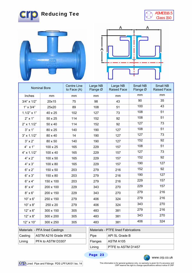
Reducing Tee
Materials - PFA lined Castings
Casting ASTM A216 Grade WCB Pipe API 5L Grade B
Lining PFA to ASTM D3307 Flanges ASTM A105
Materials - PTFE lined Fabrications
Lining PTFE to ASTM D1457
Nominal Bore Centre Line to Face (A)
Large NB Flange Ø
Large NB Raised Face
Small NB Flange Ø
Small NB Raised Face
Inches mm mm mm mm mm mm
3/4” x 1/2” 20x15 75 98 43 90 35
1” x 3/4” 25x20 89 108 51 100 43
1.1/2” x 1” 40 x 25 102 127 73 108 51
2” x 1” 50 x 25 114 152 92 108 51
2” x 1.1/2” 50 x 40 114 152 92 127 73
3” x 1” 80 x 25 140 190 127 108 51
3” x 1.1/2” 80 x 40 14 190 127 127 73
3” x 2” 80 x 50 140 190 127 152 92
4” x 1” 100 x 25 165 229 157 108 51
4” x 1.1/2” 100 x 40 165 229 157 127 73
4” x 2” 100 x 50 165 229 157 152 92
4” x 3” 100 x 80 165 229 157 190 127
6” x 2” 150 x 50 203 279 216 152 92
6” x 3” 150 x 80 203 279 216 190 127
6” x 4” 150 x 100 203 279 216 229 157
8” x 4” 200 x 100 229 343 270 229 157
8” x 6” 200 x 150 229 343 270 279 216
10” x 6” 250 x 150 279 406 324 279 216
10” x 8” 250 x 20 279 406 324 343 270
12” x 8” 300 x 200 305 483 381 343 270
12” x 10” 300 x 250 305 483 381 406 324
12” x 6” 300 x 150 305 483 381 279 216
ASME B16.5 Class 150
Lined Pipe and Fittings PDS LPF/UK/01 Iss. 14 This information is for general guidance only, no warranty is given for it’s accuracy and CRP reserve the right to change specifications without notice © CRP
Page Page 2424 www.crp.co.uk
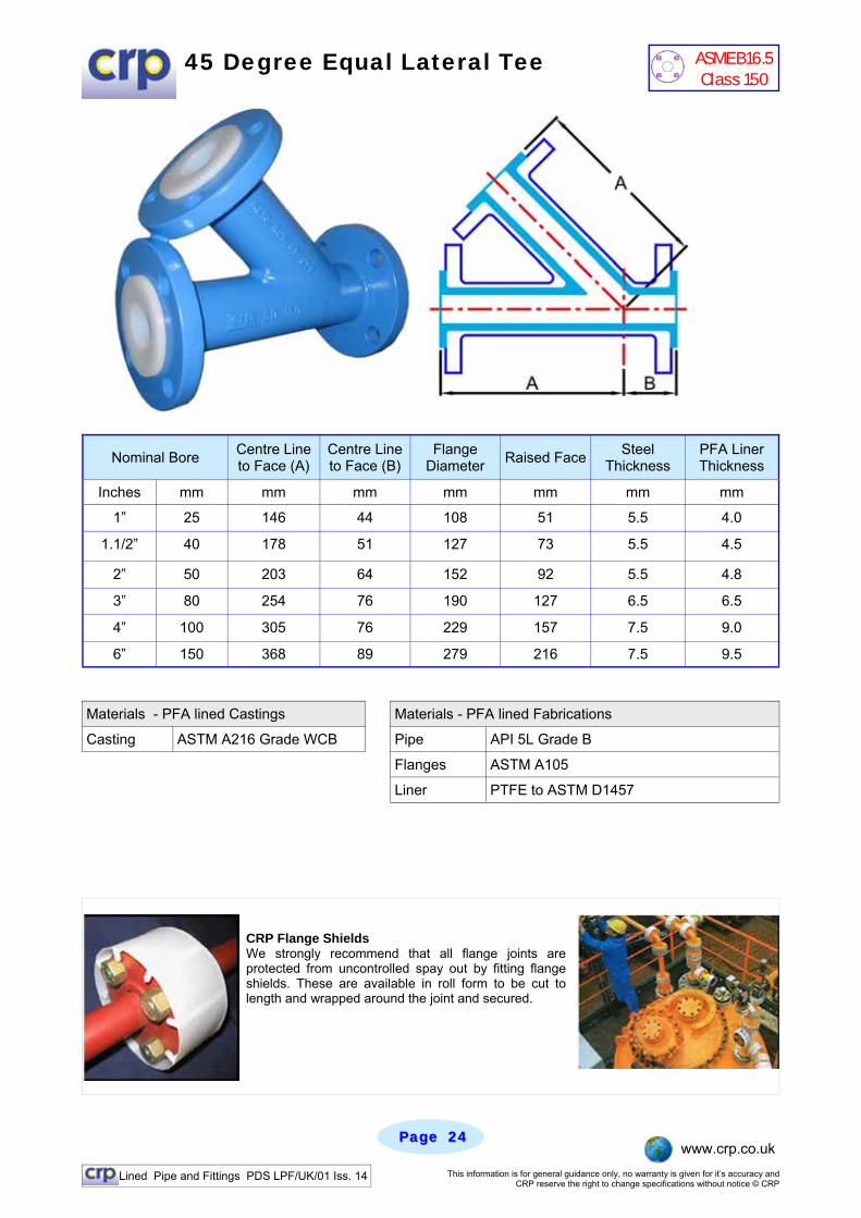
45 Degree Equal Lateral Tee
Nominal Bore Centre Line to Face (A)
Centre Line to Face (B)
Flange Diameter Raised Face Steel
Thickness PFA Liner Thickness
Inches mm mm mm mm mm mm mm
1” 25 146 44 108 51 5.5 4.0
1.1/2” 40 178 51 127 73 5.5 4.5
2” 50 203 64 152 92 5.5 4.8
3” 80 254 76 190 127 6.5 6.5
4” 100 305 76 229 157 7.5 9.0
6” 150 368 89 279 216 7.5 9.5
CRP Flange Shields We strongly recommend that all flange joints are protected from uncontrolled spay out by fitting flange shields. These are available in roll form to be cut to length and wrapped around the joint and secured.
Materials - PFA lined Castings Materials - PFA lined Fabrications
Casting ASTM A216 Grade WCB Pipe API 5L Grade B
Flanges ASTM A105
Liner PTFE to ASTM D1457
ASME B16.5 Class 150

Lined Pipe and Fittings PDS LPF/UK/01 Iss. 14 This information is for general guidance only, no warranty is given for it’s accuracy and CRP reserve the right to change specifications without notice © CRP
Page Page 2525 www.crp.co.uk
45 Degree Reducing Lateral Tee
Nominal Bore Centre Line to Face (A)
Large NB Flange Ø
Large NB Raised Face
Small NB Flange Ø
Small NB Raised Face
Inches mm mm mm mm mm mm
1.1/2” x 1” 40 x 25 178 127 73 108 51
2” x 1” 50 x 25 203 152 92 108 51
2” x 1.1/2” 50 x 40 203 152 92 127 73
3” x 1” 80 x 25 254 190 127 108 51
3” x 1.1/2” 80 x 40 254 190 127 127 73
3” x 2” 80 x 50 254 190 127 152 92
4” x 1.5” 100 x 40 305 229 157 127 73
4” x 2” 100 x 50 305 229 157 152 92
4” x 3” 100 x 80 305 229 157 190 127
Centre Line to Face (B)
mm
51
64
64
76
76
76
76
76
76
6” x 2” 150 x 50 368 89 279 216 152 92
6” x 3” 150 x 80 368 89 279 216 190 127
6” x 4” 150 x 100 368 89 279 216 229 157
Materials - PFA lined Castings Specials
Casting ASTM A216 Grade WCB
Lining PFA to ASTM D1457
Materials - PFA lined Fabrications
Pipe API 5L Grade B
Flanges ASTM 105
Lining PFA to ASTM D3307
C R P c a n manufacture many special components, All lined in PTFE or PFA. Here on the left is a custom pH probe housing.
ASME B16.5 Class 150
Lined Pipe and Fittings PDS LPF/UK/01 Iss. 14 This information is for general guidance only, no warranty is given for it’s accuracy and CRP reserve the right to change specifications without notice © CRP
Page Page 2626 www.crp.co.uk
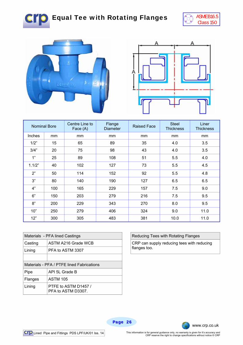
Equal Tee with Rotating Flanges
Materials - PFA lined Castings Reducing Tees with Rotating Flanges
Casting ASTM A216 Grade WCB
Lining PFA to ASTM 3307
Materials - PFA / PTFE lined Fabrications
Pipe API 5L Grade B
Flanges ASTM 105
Lining PTFE to ASTM D1457 / PFA to ASTM D3307.
CRP can supply reducing tees with reducing flanges too.
Nominal Bore Centre Line to Face (A)
Flange Diameter Raised Face Steel
Thickness Liner
Thickness
Inches mm mm mm mm mm mm
1/2” 15 65 89 35 4.0 3.5
3/4” 20 75 98 43 4.0 3.5
1” 25 89 108 51 5.5 4.0
1.1/2” 40 102 127 73 5.5 4.5
2” 50 114 152 92 5.5 4.8
3” 80 140 190 127 6.5 6.5
4” 100 165 229 157 7.5 9.0
6” 150 203 279 216 7.5 9.5
8” 200 229 343 270 8.0 9.5
10” 250 279 406 324 9.0 11.0
12” 300 305 483 381 10.0 11.0
ASME B16.5 Class 150
Lined Pipe and Fittings PDS LPF/UK/01 Iss. 14 This information is for general guidance only, no warranty is given for it’s accuracy and CRP reserve the right to change specifications without notice © CRP
Page Page 2727 www.crp.co.uk
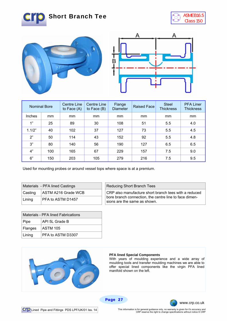
Short Branch Tee
Used for mounting probes or around vessel tops where space is at a premium.
Materials - PFA lined Castings Reducing Short Branch Tees
Casting ASTM A216 Grade WCB
Lining PFA to ASTM D1457
Materials - PFA lined Fabrications
Pipe API 5L Grade B
Flanges ASTM 105
Lining PFA to ASTM D3307
CRP also manufacture short branch tees with a reduced bore branch connection, the centre line to face dimen-sions are the same as shown.
Nominal Bore Centre Line to Face (A)
Centre Line to Face (B)
Flange Diameter Raised Face Steel
Thickness PFA Liner Thickness
Inches mm mm mm mm mm mm mm
1” 25 89 30 108 51 5.5 4.0
1.1/2” 40 102 37 127 73 5.5 4.5
2” 50 114 43 152 92 5.5 4.8
3” 80 140 56 190 127 6.5 6.5
4” 100 165 67 229 157 7.5 9.0
6” 150 203 105 279 216 7.5 9.5
PFA lined Special Components With years of moulding experience and a wide array of moulding tools and transfer moulding machines we are able to offer special lined components like the virgin PFA lined manifold shown on the left.
ASME B16.5 Class 150
Lined Pipe and Fittings PDS LPF/UK/01 Iss. 14 This information is for general guidance only, no warranty is given for it’s accuracy and CRP reserve the right to change specifications without notice © CRP
Page Page 2828 www.crp.co.uk
Materials - PFA lined Castings
Casting ASTM A216 Grade WCB Pipe API 5L Grade B
Lining PFA to ASTM D3307 Flanges ASTM A105
Materials - PTFE / PFA lined Fabrications
Lining PTFE to ASTM D1457 / PFA to ASTM D3307
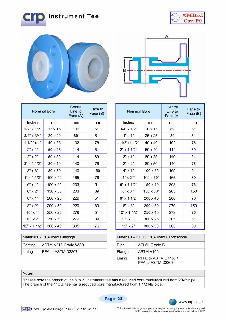
Instrument Tee
Nominal Bore Centre Line to
Face (A)
Face to Face (B) Nominal Bore
Centre Line to
Face (A)
Face to Face (B)
Inches mm mm mm Inches mm mm mm
1/2” x 1/2” 15 x 15 100 51 3/4” x 1/2” 20 x 15 89 51
3/4” x 3/4” 20 x 20 89 51 1” x 1” 25 x 25 89 51
1.1/2” x 1” 40 x 25 102 76 1.1/2”x1.1/2” 40 x 40 102 76
2” x 1” 50 x 25 114 51 2” x 1.1/2” 50 x 40 114 89
2” x 2” 50 x 50 114 89 3” x 1” 80 x 25 140 51
3” x 1.1/2” 80 x 40 140 76 3” x 2” 80 x 50 140 76
3” x 3” 80 x 80 140 150 4” x 1” 100 x 25 165 51
4” x 1.1/2” 100 x 40 165 76 4” x 2”* 100 x 50* 165 89
6” x 1” 150 x 25 203 51 6” x 1.1/2” 150 x 40 203 76
6” x 2” 150 x 50 203 89 6” x 3”* 150 x 80* 203 150
8” x 1” 200 x 25 229 51 8” x 1.1/2” 200 x 40 200 76
8” x 2” 200 x 50 229 89 8” x 3” 200 x 80 279 150
10” x 1” 250 x 25 279 51 10” x 1.1/2” 250 x 40 279 76
10” x 2” 250 x 50 279 89 12” x 1” 300 x 25 305 51
12” x 1.1/2” 300 x 40 305 76 12” x 2” 300 x 50 305 89
Notes
*Please note the branch of the 6” x 3” instrument tee has a reduced bore manufactured from 2”NB pipe. The branch of the 4” x 2” tee has a reduced bore manufactured from 1.1/2”NB pipe.
ASME B16.5 Class 150

Lined Pipe and Fittings PDS LPF/UK/01 Iss. 14 This information is for general guidance only, no warranty is given for it’s accuracy and CRP reserve the right to change specifications without notice © CRP
Page Page 2929 www.crp.co.uk
Equal Cross
Nominal Bore Centre Line to Face (A)
Flange Diameter Raised Face Steel
Thickness Liner
Thickness
Inches mm mm mm mm mm mm
1/2” 15 65 89 35 4.0 3.5
3/4” 20 75 98 43 4.0 3.5
1” 25 89 108 51 5.5 4.0
1.1/2” 40 102 127 73 5.5 4.5
2” 50 114 152 92 5.5 4.8
3” 80 140 190 127 6.5 6.5
4” 100 165 229 157 7.5 9.0
6” 150 203 279 216 7.5 9.5
8” 200 229 343 270 8.0 9.5
10” 250 279 406 324 9.0 11.0
12” 300 305 483 381 10.0 11.0
Materials - PFA lined Castings Reducing Crosses
Casting ASTM A216 Grade WCB
Lining PFA to ASTM D1457
Materials - PTFE / PFA lined Fabrications
Pipe API 5L Grade B
Flanges ASTM 105
Lining PTFE to ASTM D3307 / PFA to ASTM D1457
CRP can also supply reducing crosses upon request, centre line to face dimensions for all branches are dictated by the large nominal bore and are the same as equal crosses.
Stainless Steel Lined Pipe and Fittings CRP can supply our complete range in stainless steel, we have developed the range to provide a very cost effective alternative to lined carbon steel.
ASME B16.5 Class 150
Lined Pipe and Fittings PDS LPF/UK/01 Iss. 14 This information is for general guidance only, no warranty is given for it’s accuracy and CRP reserve the right to change specifications without notice © CRP
Page Page 3030 www.crp.co.uk
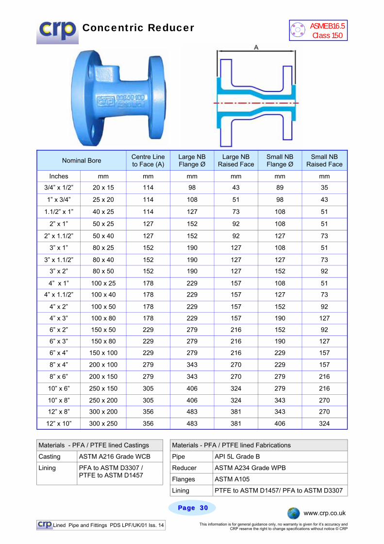
Concentric Reducer
Materials - PFA / PTFE lined Castings Materials - PFA / PTFE lined Fabrications
Casting ASTM A216 Grade WCB Pipe API 5L Grade B
PFA to ASTM D3307 / PTFE to ASTM D1457
Reducer ASTM A234 Grade WPB
Flanges ASTM A105
Lining PTFE to ASTM D1457/ PFA to ASTM D3307
Lining
Nominal Bore Centre Line to Face (A)
Large NB Flange Ø
Large NB Raised Face
Small NB Flange Ø
Small NB Raised Face
Inches mm mm mm mm mm mm
3/4” x 1/2” 20 x 15 114 98 43 89 35
1” x 3/4” 25 x 20 114 108 51 98 43
1.1/2” x 1” 40 x 25 114 127 73 108 51
2” x 1” 50 x 25 127 152 92 108 51
2” x 1.1/2” 50 x 40 127 152 92 127 73
3” x 1” 80 x 25 152 190 127 108 51
3” x 1.1/2” 80 x 40 152 190 127 127 73
3” x 2” 80 x 50 152 190 127 152 92
4” x 1” 100 x 25 178 229 157 108 51
4” x 1.1/2” 100 x 40 178 229 157 127 73
4” x 2” 100 x 50 178 229 157 152 92
4” x 3” 100 x 80 178 229 157 190 127
6” x 2” 150 x 50 229 279 216 152 92
6” x 3” 150 x 80 229 279 216 190 127
6” x 4” 150 x 100 229 279 216 229 157
8” x 4” 200 x 100 279 343 270 229 157
8” x 6” 200 x 150 279 343 270 279 216
10” x 6” 250 x 150 305 406 324 279 216
10” x 8” 250 x 200 305 406 324 343 270
12” x 8” 300 x 200 356 483 381 343 270
12” x 10” 300 x 250 356 483 381 406 324
ASME B16.5 Class 150
Lined Pipe and Fittings PDS LPF/UK/01 Iss. 14 This information is for general guidance only, no warranty is given for it’s accuracy and CRP reserve the right to change specifications without notice © CRP
Page Page 3131 www.crp.co.uk
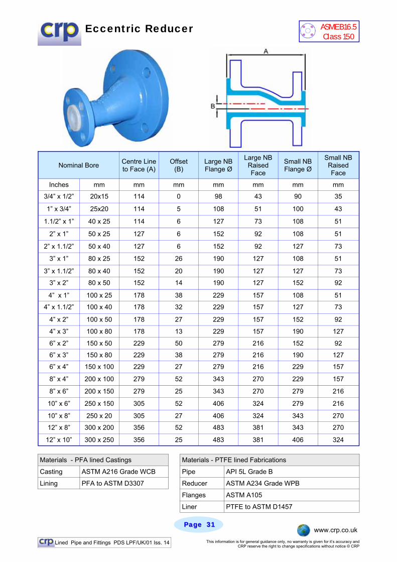
Eccentric Reducer
Materials - PFA lined Castings
Casting ASTM A216 Grade WCB Pipe API 5L Grade B
Lining PFA to ASTM D3307 Reducer ASTM A234 Grade WPB
Flanges ASTM A105
Liner PTFE to ASTM D1457
Materials - PTFE lined Fabrications
Nominal Bore Centre Line to Face (A)
Large NB Flange Ø
Large NB Raised Face
Small NB Flange Ø
Small NB Raised Face
Inches mm mm mm mm mm mm
3/4” x 1/2” 20x15 114 98 43 90 35
1” x 3/4” 25x20 114 108 51 100 43
1.1/2” x 1” 40 x 25 114 127 73 108 51
2” x 1” 50 x 25 127 152 92 108 51
2” x 1.1/2” 50 x 40 127 152 92 127 73
3” x 1” 80 x 25 152 190 127 108 51
3” x 1.1/2” 80 x 40 152 190 127 127 73
3” x 2” 80 x 50 152 190 127 152 92
4” x 1” 100 x 25 178 229 157 108 51
4” x 1.1/2” 100 x 40 178 229 157 127 73
4” x 2” 100 x 50 178 229 157 152 92
4” x 3” 100 x 80 178 229 157 190 127
6” x 2” 150 x 50 229 279 216 152 92
6” x 3” 150 x 80 229 279 216 190 127
6” x 4” 150 x 100 229 279 216 229 157
8” x 4” 200 x 100 279 343 270 229 157
8” x 6” 200 x 150 279 343 270 279 216
10” x 6” 250 x 150 305 406 324 279 216
10” x 8” 250 x 20 305 406 324 343 270
12” x 8” 300 x 200 356 483 381 343 270
12” x 10” 300 x 250 356 483 381 406 324
Offset (B)
mm
0
5
6
6
6
26
20
14
38
32
27
13
50
38
27
52
25
52
27
52
25
ASME B16.5 Class 150
Lined Pipe and Fittings PDS LPF/UK/01 Iss. 14 This information is for general guidance only, no warranty is given for it’s accuracy and CRP reserve the right to change specifications without notice © CRP
Page Page 3232 www.crp.co.uk
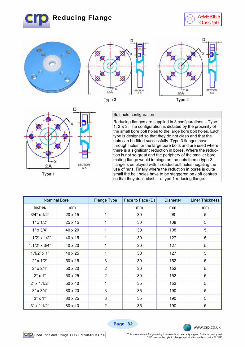
Reducing Flange
Nominal Bore Flange Type Face to Face (D) Diameter Liner Thickness
Inches mm mm mm mm
3/4” x 1/2” 20 x 15 1 30 98 5
1” x 1/2” 25 x 15 1 30 108 5
1” x 3/4” 40 x 20 1 30 108 5
1.1/2” x 1/2” 40 x 15 1 30 127 5
1.1/2” x 3/4” 40 x 20 1 30 127 5
1.1/2” x 1” 40 x 25 1 30 127 5
2” x 1/2” 50 x 15 3 30 152 5
2” x 3/4” 50 x 20 2 30 152 5
2” x 1” 50 x 25 2 30 152 5
2” x 1.1/2” 50 x 40 1 35 152 5
3” x 3/4” 80 x 20 3 35 190 5
3” x 1” 80 x 25 3 35 190 5
3” x 1.1/2” 80 x 40 2 35 190 5
Type 3 Type 2
Type 1
Bolt hole configuration
Reducing flanges are supplied in 3 configurations – Type 1, 2 & 3, The configuration is dictated by the proximity of the small bore bolt holes to the large bore bolt holes. Each type is designed so that they do not clash and that the nuts can be fitted successfully. Type 3 flanges have through holes for the large bore bolts and are used where there is a significant reduction in bores. Where the reduc-tion is not so great and the periphery of the smaller bore mating flange would impinge on the nuts then a type 2 flange is employed with threaded bolt holes negating the use of nuts. Finally where the reduction in bores is quite small the bolt holes have to be staggered on / off centres so that they don’t clash – a type 1 reducing flange.
ASME B16.5 Class 150
Lined Pipe and Fittings PDS LPF/UK/01 Iss. 14 This information is for general guidance only, no warranty is given for it’s accuracy and CRP reserve the right to change specifications without notice © CRP
Page Page 3333 www.crp.co.uk
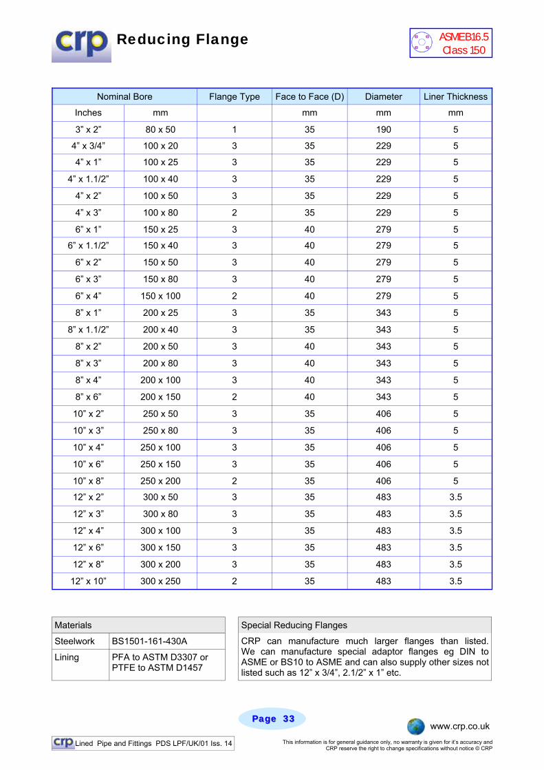
Reducing Flange
Materials Special Reducing Flanges
Steelwork BS1501-161-430A
Lining PFA to ASTM D3307 or PTFE to ASTM D1457
CRP can manufacture much larger flanges than listed. We can manufacture special adaptor flanges eg DIN to ASME or BS10 to ASME and can also supply other sizes not listed such as 12” x 3/4”, 2.1/2” x 1” etc.
Nominal Bore Flange Type Face to Face (D) Diameter Liner Thickness
Inches mm mm mm mm
3” x 2” 80 x 50 1 35 190 5
4” x 3/4” 100 x 20 3 35 229 5
4” x 1” 100 x 25 3 35 229 5
4” x 1.1/2” 100 x 40 3 35 229 5
4” x 2” 100 x 50 3 35 229 5
4” x 3” 100 x 80 2 35 229 5
6” x 1” 150 x 25 3 40 279 5
6” x 1.1/2” 150 x 40 3 40 279 5
6” x 2” 150 x 50 3 40 279 5
6” x 3” 150 x 80 3 40 279 5
6” x 4” 150 x 100 2 40 279 5
8” x 1” 200 x 25 3 35 343 5
8” x 1.1/2” 200 x 40 3 35 343 5
8” x 2” 200 x 50 3 40 343 5
8” x 3” 200 x 80 3 40 343 5
8” x 4” 200 x 100 3 40 343 5
8” x 6” 200 x 150 2 40 343 5
10” x 2” 250 x 50 3 35 406 5
10” x 3” 250 x 80 3 35 406 5
10” x 4” 250 x 100 3 35 406 5
10” x 6” 250 x 150 3 35 406 5
10” x 8” 250 x 200 2 35 406 5
12” x 2” 300 x 50 3 35 483 3.5
12” x 3” 300 x 80 3 35 483 3.5
12” x 4” 300 x 100 3 35 483 3.5
12” x 6” 300 x 150 3 35 483 3.5
12” x 8” 300 x 200 3 35 483 3.5
12” x 10” 300 x 250 2 35 483 3.5
ASME B16.5 Class 150
Lined Pipe and Fittings PDS LPF/UK/01 Iss. 14 This information is for general guidance only, no warranty is given for it’s accuracy and CRP reserve the right to change specifications without notice © CRP
Page Page 3434 www.crp.co.uk
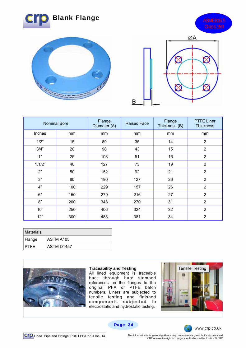
Blank Flange ASME B16.5 Class 150
Nominal Bore Flange Diameter (A) Raised Face Flange
Thickness (B) PTFE Liner Thickness
Inches mm mm mm mm mm
1/2” 15 89 35 14 2
3/4” 20 98 43 15 2
1” 25 108 51 16 2
1.1/2” 40 127 73 19 2
2” 50 152 92 21 2
3” 80 190 127 26 2
4” 100 229 157 26 2
6” 150 279 216 27 2
8” 200 343 270 31 2
10” 250 406 324 32 2
12” 300 483 381 34 2
Materials
Flange ASTM A105
PTFE ASTM D1457
Traceability and Testing All lined equipment is traceable back through hard stamped references on the flanges to the original PFA or PTFE batch numbers. Liners are subjected to tensile testing and finished c o m p o n e n t s s u b j e c t e d t o electrostatic and hydrostatic testing.
Tensile Testing

Lined Pipe and Fittings PDS LPF/UK/01 Iss. 14 This information is for general guidance only, no warranty is given for it’s accuracy and CRP reserve the right to change specifications without notice © CRP
Page Page 3535 www.crp.co.uk
Blanking Spade
Nominal Bore Spade Diameter (A) Handle Length (B) PTFE Liner
Thickness
Inches mm mm mm mm
1/2” 15 44 102 2
3/4” 20 54 110 2
1” 25 63 148 2
1.1/2” 40 82 156 2
2” 50 102 162 2
3” 80 133 178 2
4” 100 171 194 2
6” 150 219 220 2
8” 200 277 250 2
10” 250 337 300 2
12” 300 407 340 2
Materials
Flange ASTM A105
PTFE ASTM D1457
Orifice Plates CRP can supply solid PTFE orifice plates with holes drilled to suit your application. Orifice plates can be used to control flow or help in flow measurement. We can supply them to suit a wide range of pipe nominal bores, they are generally supplied in virgin PTFE but other materials can be provided.
ASME B16.5 Class 150

Lined Pipe and Fittings PDS LPF/UK/01 Iss. 14 This information is for general guidance only, no warranty is given for it’s accuracy and CRP reserve the right to change specifications without notice © CRP
Page Page 3636 www.crp.co.uk
Solid PTFE Sliding Spectacle Blind
Nominal Bore Flange Diameter (A) Dimension (B) Face to Face (C)
Inches mm mm mm mm
1/2” 15 89 60 10
3/4” 20 98 70 10
1” 25 108 79 10
1.1/2” 40 127 98 10
2” 50 152 121 16
3” 80 190 152 16
4” 100 229 191 27
6” 150 279 241 27
8” 200 343 298 27
10” 250 406 362 27
12” 300 483 432 27
Materials
PTFE ASTM D1457
Installation and Operating Guidance Detailed storage, installation and operation guidance can be found for all CRP products in our handy “User Manual” This is supplied with all deliveries and can also be downloaded from our website from the Technical Info section.
ASME B16.5 Class 150
Lined Pipe and Fittings PDS LPF/UK/01 Iss. 14 This information is for general guidance only, no warranty is given for it’s accuracy and CRP reserve the right to change specifications without notice © CRP
Page Page 3737 www.crp.co.uk
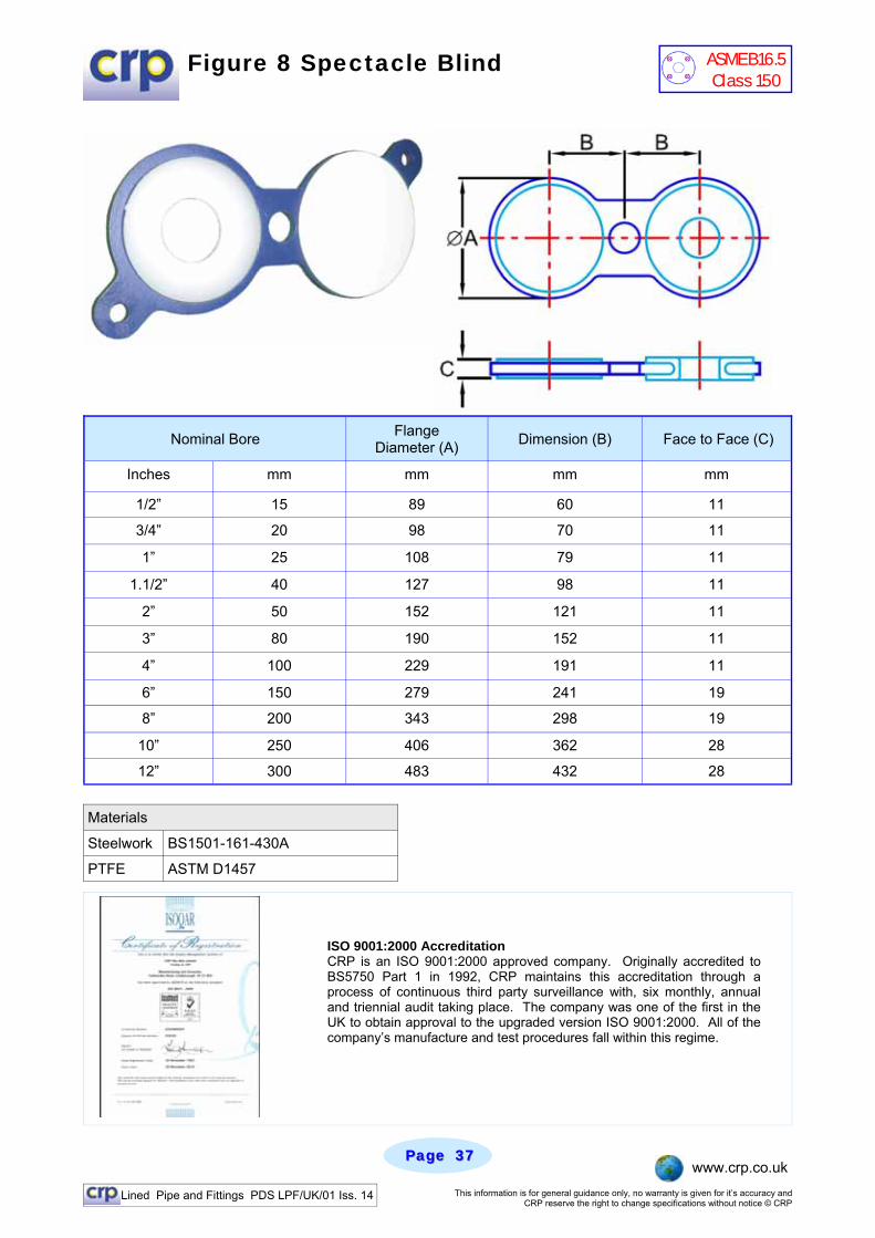
Figure 8 Spectacle Blind
Nominal Bore Flange Diameter (A) Dimension (B) Face to Face (C)
Inches mm mm mm mm
1/2” 15 89 60 11
3/4” 20 98 70 11
1” 25 108 79 11
1.1/2” 40 127 98 11
2” 50 152 121 11
3” 80 190 152 11
4” 100 229 191 11
6” 150 279 241 19
8” 200 343 298 19
10” 250 406 362 28
12” 300 483 432 28
Materials
Steelwork BS1501-161-430A
PTFE ASTM D1457
ISO 9001:2000 Accreditation CRP is an ISO 9001:2000 approved company. Originally accredited to BS5750 Part 1 in 1992, CRP maintains this accreditation through a process of continuous third party surveillance with, six monthly, annual and triennial audit taking place. The company was one of the first in the UK to obtain approval to the upgraded version ISO 9001:2000. All of the company’s manufacture and test procedures fall within this regime.
ASME B16.5 Class 150
Lined Pipe and Fittings PDS LPF/UK/01 Iss. 14 This information is for general guidance only, no warranty is given for it’s accuracy and CRP reserve the right to change specifications without notice © CRP
Page Page 3838 www.crp.co.uk
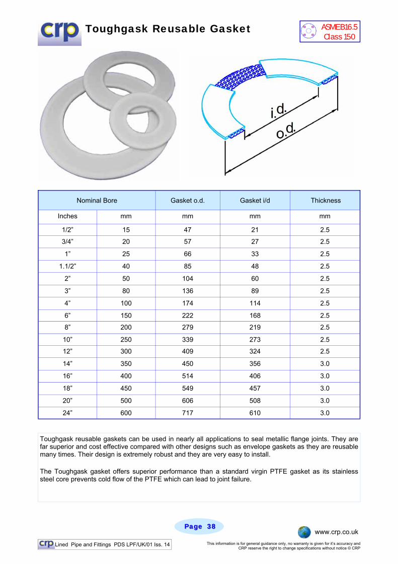
Toughgask Reusable Gasket
Nominal Bore Gasket o.d. Gasket i/d Thickness
Inches mm mm mm mm
1/2” 15 47 21 2.5
3/4” 20 57 27 2.5
1” 25 66 33 2.5
1.1/2” 40 85 48 2.5
2” 50 104 60 2.5
3” 80 136 89 2.5
4” 100 174 114 2.5
6” 150 222 168 2.5
8” 200 279 219 2.5
10” 250 339 273 2.5
12” 300 409 324 2.5
14” 350 450 356 3.0
16” 400 514 406 3.0
18” 450 549 457 3.0
20” 500 606 508 3.0
24” 600 717 610 3.0
Toughgask reusable gaskets can be used in nearly all applications to seal metallic flange joints. They are far superior and cost effective compared with other designs such as envelope gaskets as they are reusable many times. Their design is extremely robust and they are very easy to install.
The Toughgask gasket offers superior performance than a standard virgin PTFE gasket as its stainless steel core prevents cold flow of the PTFE which can lead to joint failure.
ASME B16.5 Class 150
Lined Pipe and Fittings PDS LPF/UK/01 Iss. 14 This information is for general guidance only, no warranty is given for it’s accuracy and CRP reserve the right to change specifications without notice © CRP
Page Page 3939 www.crp.co.uk
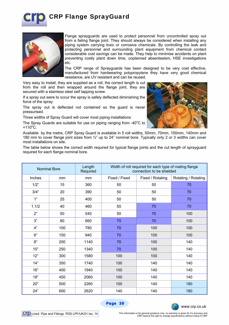
CRP Flange SprayGuard
Flange sprayguards are used to protect personnel from uncontrolled spray out from a failing flange joint. They should always be considered when installing any piping system carrying toxic or corrosive chemicals. By controlling the leak and protecting personnel and surrounding plant equipment from chemical contact considerable cost savings can be made. They help to minimise accidents on plant preventing costly plant down time, unplanned absenteeism, HSE investigations etc. The CRP range of Sprayguards has been designed to be very cost effective, manufactured from hardwearing polypropylene they have very good chemical resistance, are UV resistant and can be reused.
Very easy to install, they are supplied as a roll, the correct length is cut from the roll and then wrapped around the flange joint, they are secured with a stainless steel self tapping screw. If a spray out were to occur the spray is safely deflected diminishing the force of the spray. The spray out is deflected not contained so the guard is never pressurised. Three widths of Spray Guard will cover most piping installations The Spray Guards are suitable for use on piping ranging from -40oC to +110oC. Available by the metre, CRP Spray Guard is available in 5 roll widths, 50mm, 70mm, 100mm, 140mm and 180 mm to cover flange joint sizes from ½” up to 24” nominal bore. Typically only 2 or 3 widths can cover most installations on site. The table below shows the correct width required for typical flange joints and the cut length of sprayguard required for each flange nominal bore.
Nominal Bore Length Required
Inches mm mm Fixed / Fixed Fixed / Rotating Rotating / Rotating
1/2” 15 360 50 50 70
3/4” 20 390 50 50 70
1” 25 400 50 50 70
1.1/2 40 460 50 70 70
2” 50 540 50 70 100
3” 80 660 70 70 100
4” 100 780 70 100 100
6” 150 940 70 100 100
8” 200 1140 70 100 140
10” 250 1340 70 100 140
12” 300 1580 100 100 140
14” 350 1740 100 140 140
16” 400 1940 100 140 140
18” 450 2060 100 140 140
20” 500 2260 100 140 180
24” 600 2620 140 140 180
Width of roll required for each type of mating flange connection to be shielded
Lined Pipe and Fittings PDS LPF/UK/01 Iss. 14 This information is for general guidance only, no warranty is given for it’s accuracy and CRP reserve the right to change specifications without notice © CRP
Page Page 4040 www.crp.co.uk
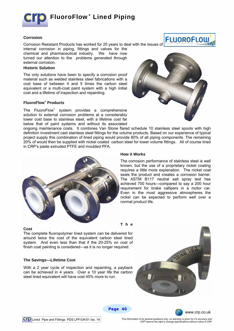
FluoroFlow+ Lined Piping
Corrosion Corrosion Resistant Products has worked for 25 years to deal with the issues of internal corrosion in piping, fittings and valves for the chemical and pharmaceutical industry. We have now turned our attention to the problems generated through external corrosion. Historic Solution The only solutions have been to specify a corrosion proof material such as welded stainless steel fabrications with a cost base of between 4 and 5 times the carbon steel equivalent or a multi-coat paint system with a high initial cost and a lifetime of inspection and repainting. FluoroFlow+ Products
The FluoroFlow+ system provides a comprehensive solution to external corrosion problems at a considerably lower cost base to stainless steel, with a lifetime cost far below that of paint systems and without its associated ongoing maintenance costs. It combines Van Stone flared schedule 10 stainless steel spools with high definition investment cast stainless steel fittings for the volume products. Based on our experience of typical project supply this combination of lined piping would provide 80% of all piping components. The remaining 20% of would then be supplied with nickel coated carbon steel for lower volume fittings. All of course lined in CRP’s paste extruded PTFE and moulded PFA.
How it Works
The corrosion performance of stainless steel is well known, but the use of a proprietary nickel coating requires a little more explanation. The nickel coat seals the product and creates a corrosion barrier. The ASTM B117 neutral salt spray test has achieved 700 hours—compared to say a 200 hour requirement for brake callipers in a motor car. Even in the most aggressive atmospheres the nickel can be expected to perform well over a normal product life. T h e
Cost The complete fluoropolymer lined system can be delivered for around twice the cost of the equivalent carbon steel lined system. And even less than that if the 20-25% on cost of finish coat painting is considered—as it is no longer required.
The Savings—Lifetime Cost
With a 2 year cycle of inspection and repainting, a payback can be achieved in 4 years. Over a 10 year life the carbon steel lined equivalent will have cost 45% more to run.
Lined Pipe and Fittings PDS LPF/UK/01 Iss. 14 This information is for general guidance only, no warranty is given for it’s accuracy and CRP reserve the right to change specifications without notice © CRP
Page Page 4141 www.crp.co.uk
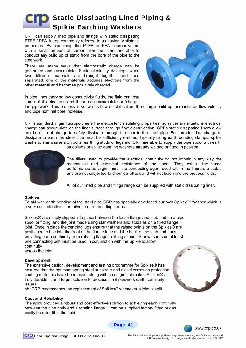
Static Dissipating Lined Piping & Spikie Earthing Washers
CRP can supply lined pipe and fittings with static dissipating PTFE / PFA liners, commonly referred to as having ‘Antistatic’ properties. By combining the PTFE or PFA fluoropolymers with a small amount of carbon filler the liners are able to conduct any build up of static from the bore of the pipe to the steelwork. There are many ways that electrostatic charge can be generated and accumulate. Static electricity develops when two different materials are brought together and then separated, one of the materials acquires electrons from the other material and becomes positively charged. In pipe lines carrying low conductivity fluids, the fluid can lose some of it’s electrons and these can accumulate or ‘charge’ the pipework. This process is known as flow electrification, the charge build up increases as flow velocity and pipe nominal bore increase. CRPs standard virgin fluoropolymers have excellent insulating properties, so in certain situations electrical charge can accumulate on the liner surface through flow electrification. CRPs static dissipating liners allow any build up of charge to safely dissipate through the liner to the steel pipe. For the electrical charge to dissipate to earth the steel pipe must be sufficiently earthed, typically using earth bonding clamps, spikie washers, star washers on bolts, earthing studs or lugs etc. CRP are able to supply the pipe spool with earth
studs/lugs or spikie earthing washers already welded or fitted in position. The fillers used to provide the electrical continuity do not impair in any way the mechanical and chemical resistance of the liners. They exhibit the same performance as virgin liners, the conducting agent used within the liners are stable and are not subjected to chemical attack and will not leach into the process fluids. All of our lined pipe and fittings range can be supplied with static dissipating liner.
Spikies To aid with earth bonding of the steel pipe CRP has specially developed our own Spikey™ washer which is a very cost effective alternative to earth bonding straps. Spikies® are simply slipped into place between the loose flange and stub end on a pipe spool or fitting, and the joint made using star washers and studs as on a fixed flange joint. Once in place the centring lugs ensure that the raised points on the Spikies® are positioned to bite into the front of the flange face and the back of the stub end, thus providing earth continuity from rotating flange to fitting / spool. Star washers on at least one connecting bolt must be used in conjunction with the Spikie to allow continuity across the joint. Development The extensive design, development and testing programme for Spikies® has ensured that the optimum spring steel substrate and nickel corrosion protection coating materials have been used, along with a design that makes Spikies® a truly durable fit and forget solution to process plant pipework earth continuity issues. nb. CRP recommends the replacement of Spikies® whenever a joint is split. Cost and Reliability The spiky provides a robust and cost effective solution to achieving earth continuity between the pipe body and a rotating flange. It can be supplied factory fitted or can easily be retro-fit in the field.

Lined Pipe and Fittings PDS LPF/UK/01 Iss. 14 This information is for general guidance only, no warranty is given for it’s accuracy and CRP reserve the right to change specifications without notice © CRP
Page Page 4242 www.crp.co.uk
Super Weight Liners For Halogen Service
Bromine along with other members of the halogen family is highly reactive, this can lead over time to particles permeating through fluoropolymer linings used to carry this highly corrosive chemical. Working closely with a global agricultural chemical manufacturer CRP has developed a special lined piping range utilising super-weight paste extruded PTFE liners and PFA moulded fittings. PFA is well known for its excellent permeation resistance properties often double that of PTFE and a natural choice for Bromine applications. Life spans of piping are extended by supplying extra heavy wall PTFE liners up to 50% thicker than our standard heavy wall liners Super Weight Piping Specification
• PFA lined fittings – Heavy wall typically 5mm or more thick. • PTFE paste extruded liners. Offer superior permeation resistance than isostatically formed liners • ¼” vent bosses supplied at each end of pipe spools, fitted with PTFE vent plugs, help minimise local
corrosion. • All piping supplied spray painted in yellow preventing product mix up on site. • All usual CRP quality, testing & inspection standards adhered to.
Lined Pipe and Fittings PDS LPF/UK/01 Iss. 14 This information is for general guidance only, no warranty is given for it’s accuracy and CRP reserve the right to change specifications without notice © CRP
Page Page 4343 www.crp.co.uk
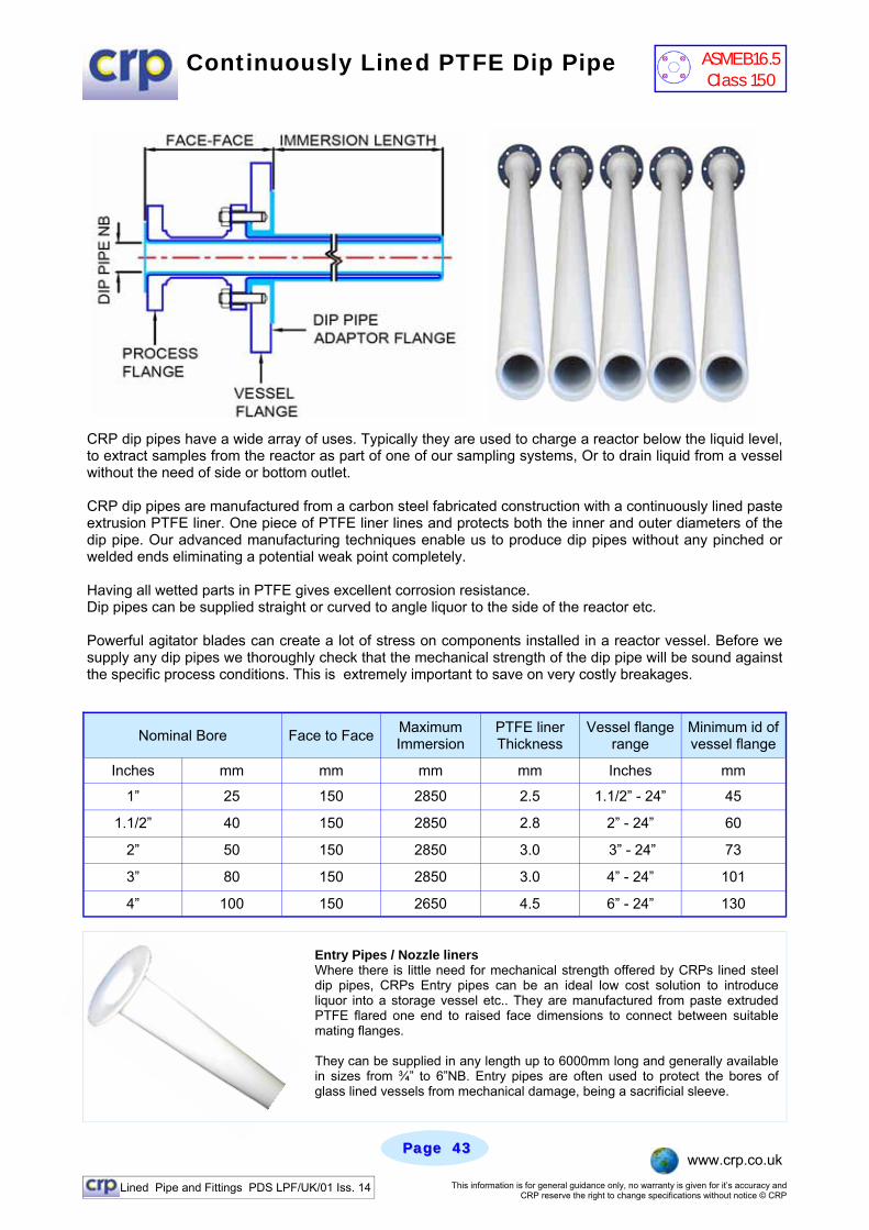
Continuously Lined PTFE Dip Pipe
CRP dip pipes have a wide array of uses. Typically they are used to charge a reactor below the liquid level, to extract samples from the reactor as part of one of our sampling systems, Or to drain liquid from a vessel without the need of side or bottom outlet. CRP dip pipes are manufactured from a carbon steel fabricated construction with a continuously lined paste extrusion PTFE liner. One piece of PTFE liner lines and protects both the inner and outer diameters of the dip pipe. Our advanced manufacturing techniques enable us to produce dip pipes without any pinched or welded ends eliminating a potential weak point completely. Having all wetted parts in PTFE gives excellent corrosion resistance. Dip pipes can be supplied straight or curved to angle liquor to the side of the reactor etc. Powerful agitator blades can create a lot of stress on components installed in a reactor vessel. Before we supply any dip pipes we thoroughly check that the mechanical strength of the dip pipe will be sound against the specific process conditions. This is extremely important to save on very costly breakages.
Nominal Bore Face to Face Maximum Immersion
PTFE liner Thickness
Vessel flange range
Minimum id of vessel flange
Inches mm mm mm mm Inches mm
1” 25 150 2850 2.5 1.1/2” - 24” 45
1.1/2” 40 150 2850 2.8 2” - 24” 60
2” 50 150 2850 3.0 3” - 24” 73
3” 80 150 2850 3.0 4” - 24” 101
4” 100 150 2650 4.5 6” - 24” 130
Entry Pipes / Nozzle liners Where there is little need for mechanical strength offered by CRPs lined steel dip pipes, CRPs Entry pipes can be an ideal low cost solution to introduce liquor into a storage vessel etc.. They are manufactured from paste extruded PTFE flared one end to raised face dimensions to connect between suitable mating flanges. They can be supplied in any length up to 6000mm long and generally available in sizes from ¾” to 6”NB. Entry pipes are often used to protect the bores of glass lined vessels from mechanical damage, being a sacrificial sleeve.
ASME B16.5 Class 150