crs39-03-0100-132 rev 3 - silicon sensing | … sensor temperature coef fi cient, mv/ c-13.7 -11.7...
TRANSCRIPT
Analogue Angular Rate Sensor
High Performance MEMS Gyroscope
CRS39 Technical Datasheet
© Copyright 2016 Silicon Sensing Systems Limited. All rights reserved. Silicon Sensing is an Atlantic Inertial Systems, Sumitomo Precision Products joint venture company.Specifi cation subject to change without notice.
Page 1CRS39-03-0100-132 Rev 3
Features• Proven and Robust silicon MEMS vibrating ring structure
• FOG-like performance
• DTG-like size and performance
• Low Bias Instability (0.1°/h)
• Excellent Angle Random Walk (0.01°/h)
• Ultra-low noise (<0.006°/s rms, 10Hz)
• Optimised for low rate range environments (e.g. North Finding)
• Precision analogue output
• Wide range from -10°C to +110°C
• High shock and vibration rejection
• Three temperature sensors for precision thermal compensation
• MEMS frequency output for precision thermal compensation
• RoHS Compliant
• Packaged and unpackaged options
Applications• Platform Stabilization
• Precision Surveying
• Downhole Surveying
• North Finding
• Maritime Guidance and Control
• Gyro-compassing and Heading Control
• Autonomous Vehicles and ROVs
• Rail Track monitoring
• Robotics
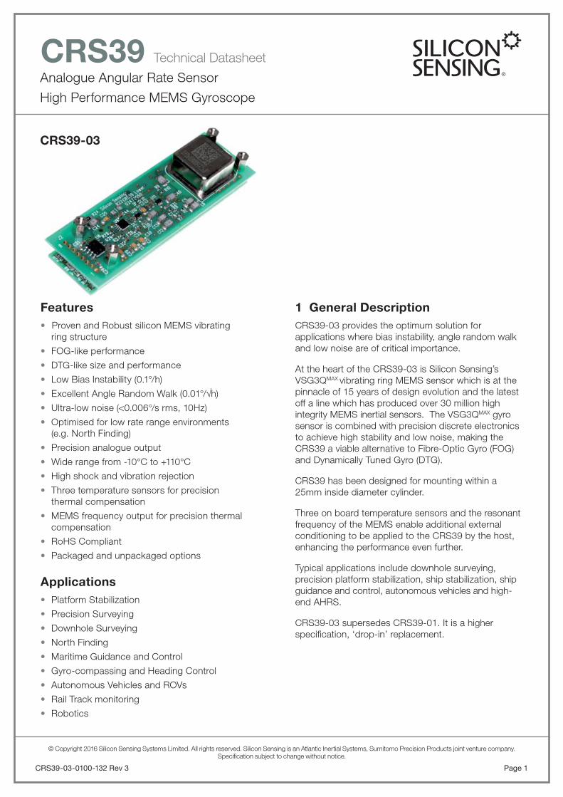
1 General DescriptionCRS39-03 provides the optimum solution for applications where bias instability, angle random walk and low noise are of critical importance.
At the heart of the CRS39-03 is Silicon Sensing’s VSG3QMAX vibrating ring MEMS sensor which is at the pinnacle of 15 years of design evolution and the latest off a line which has produced over 30 million high integrity MEMS inertial sensors. The VSG3QMAX gyro sensor is combined with precision discrete electronics to achieve high stability and low noise, making the CRS39 a viable alternative to Fibre-Optic Gyro (FOG) and Dynamically Tuned Gyro (DTG).
CRS39 has been designed for mounting within a 25mm inside diameter cylinder.
Three on board temperature sensors and the resonant frequency of the MEMS enable additional external conditioning to be applied to the CRS39 by the host, enhancing the performance even further.
Typical applications include downhole surveying, precision platform stabilization, ship stabilization, ship guidance and control, autonomous vehicles and high-end AHRS.
CRS39-03 supersedes CRS39-01. It is a higher specifi cation, ‘drop-in’ replacement.
CRS39-03
Analogue Angular Rate Sensor
High Performance MEMS Gyroscope
CRS39 Technical Datasheet
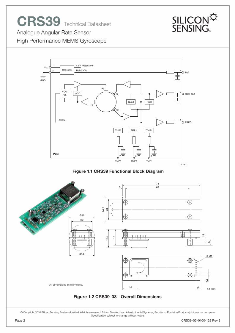
Figure 1.2 CRS39-03 - Overall Dimensions
Figure 1.1 CRS39 Functional Block Diagram
CRS39-03-0100-132 Rev 3Page 2
© Copyright 2016 Silicon Sensing Systems Limited. All rights reserved. Silicon Sensing is an Atlantic Inertial Systems, Sumitomo Precision Products joint venture company.Specifi cation subject to change without notice.
Quad Real
SD
PD
PP
SP
Rate_Out
Vcc
GND
4.6V (Regulated)
Ref (2.4V)
3
Ref
FREQ8
AGCVCOPLL
Regulator
TMP3 TMP2 TMP1
28kHz
C.G.18617
42
1
TMP3
7
TMP2
6
TMP1
5PCB
All dimensions in millimetres.
75
20
20
Ø25
7-2
8-Ø1
16
17.9
24.5
24.5
16 4
1
8
62
+
3
77
1.8
6
C.G. 18621

Analogue Angular Rate Sensor
High Performance MEMS Gyroscope
CRS39 Technical Datasheet
Page 3CRS39-03-0100-132 Rev 3
© Copyright 2016 Silicon Sensing Systems Limited. All rights reserved. Silicon Sensing is an Atlantic Inertial Systems, Sumitomo Precision Products joint venture company.Specifi cation subject to change without notice.
2 Ordering Information
Part Number Package DescriptionOverall
Dimensions
mm
CRS39-03-0100Single - axis high performance
MEMS gyro (unpackaged).
Bare PCB assembly is intended for mounting within the user’s application such as a tube (25mm diameter), or
other enclosure.
75 x 24.5 x 19.0
3 Specifi cationUnless otherwise specifi ed the following specifi cationvalues assume Vdd = 4.9 to 5.25 V over the temperaturerange -10 to +110°C.
Parameter Minimum Typical Maximum Notes
Angular Rate Range, °/s <-25 – >+25 –
Bias Setting Error, Volts -0.10 ±0.030 +0.10Bias setting error at
+45°C
Bias Variation OverTemperature, °/h
-500 ±60 +500Referenced to the
setting point at +45°C
Bias Instability, °/h – 0.10 –
As measured using the Allan Variance method,
at constant ambient temperature
Angle Random Walk, °/h – 0.015 –
As measured using the Allan Variance method,
at constant ambient temperature
Bandwidth, Hz. 15 25 35 -3dB point
Scale Factor, mV/°/sat +45°C
79.6 80.0 80.4 –
Scale Factor Error over Temperature, %
-1.0 ±0.2 +1.0Referenced to the
setting point at +45°C
Scale Factor Non-Linearity Error, % of Full Scale
– 0.006 0.05 –
Noise to 10Hz, °/s rms – 0.006 0.01 –
Wideband Noise, °/s rms – 0.03 0.05 –
Start Up Time, seconds – – 1.0Full performance will
require additional time for thermal stability
Cross Axis Sensitivity, %-3.5%(-2.0°)
±1.2%(0.7°)
+3.5%(+2.0°)
–

Analogue Angular Rate Sensor
High Performance MEMS Gyroscope
CRS39 Technical Datasheet
CRS39-03-0100-132 Rev 3Page 4
© Copyright 2016 Silicon Sensing Systems Limited. All rights reserved. Silicon Sensing is an Atlantic Inertial Systems, Sumitomo Precision Products joint venture company.Specifi cation subject to change without notice.
4 Power Requirements
Parameter Minimum Typical Maximum Notes
Supply Voltage, Vdd, Volts 4.9 5.0 5.25Minimum of 4.9V is required for internal
regulation
Current, mA – 80 100 –
Noise13.5kHz to 14.5kHz
– – 0.5mVPower supplyripple (pk - pk)
Noise40.5kHz to 43.5kHz
– – 5.0mVPower supplyripple (pk - pk)
5 Frequency and Temperature Output Characteristics
Parameter Minimum Typical Maximum Notes
Frequency output, kHz 27.0 28.0 29.0
This signal is 2x resonant frequency of
the MEMS structure and can be used to measure the MEMS temperature
Resonant Frequency Temperature Coeffi cient, Hz/°C
-0.90 -0.80 -0.70 –
TMP1, 2 and 3, Volts at +45°C
-1.16 -1.06 -0.96 Referenced to Ref.
Temperature Sensor Temperature Coeffi cient, mV/°C
-13.7 -11.7 -9.7LM20B temperature
sensor
6 Operating and Storage Environmental
Parameter Minimum Typical Maximum Notes
Operating Temperature Range °C
-10 – +110 –
Non-operating Temperature Range °C
-40 – +130 –
OperationalShock, g
– – 250 For 1.7ms half-sine
Powered andNon-operational Shock Survival, g
– – 1,000 For 1.0ms half-sine
Note: The shape of the CRS39-03 can make it susceptible to resonances when used in an environment with high shock or vibration levels. In these circumstances, it is recommended that additional supports along the edgesof the PCB are provided.
Analogue Angular Rate Sensor
High Performance MEMS Gyroscope
CRS39 Technical Datasheet
Page 5CRS39-03-0100-132 Rev 3
© Copyright 2016 Silicon Sensing Systems Limited. All rights reserved. Silicon Sensing is an Atlantic Inertial Systems, Sumitomo Precision Products joint venture company.Specifi cation subject to change without notice.
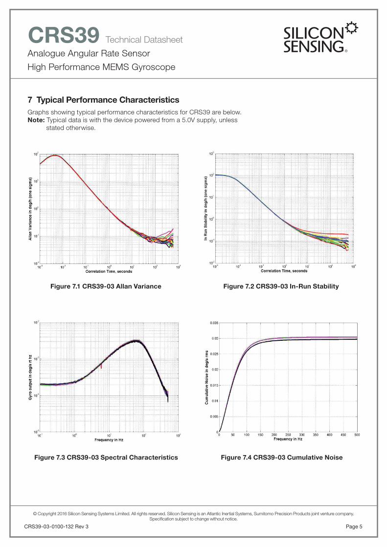
Figure 7.3 CRS39-03 Spectral Characteristics
7 Typical Performance CharacteristicsGraphs showing typical performance characteristics for CRS39 are below. Note: Typical data is with the device powered from a 5.0V supply, unless stated otherwise.
Figure 7.4 CRS39-03 Cumulative Noise
Figure 7.1 CRS39-03 Allan Variance Figure 7.2 CRS39-03 In-Run Stability

Analogue Angular Rate Sensor
High Performance MEMS Gyroscope
CRS39 Technical Datasheet
CRS39-03-0100-132 Rev 3Page 6
© Copyright 2016 Silicon Sensing Systems Limited. All rights reserved. Silicon Sensing is an Atlantic Inertial Systems, Sumitomo Precision Products joint venture company.Specifi cation subject to change without notice.
Typical Performance Characteristics Continued
Figure 7.7 CRS39-03 Normalised Bias Error (dph) vs Temperature
Figure 7.8 CRS39-03 Normalised Scale Factor Error (%) vs Temperature
Figure 7.5 CRS39-03 Bias Error (dph)vs Temperature
Figure 7.6 CRS39-03 Scale Factor Error (%)vs Temperature

Analogue Angular Rate Sensor
High Performance MEMS Gyroscope
CRS39 Technical Datasheet
Page 7CRS39-03-0100-132 Rev 3
© Copyright 2016 Silicon Sensing Systems Limited. All rights reserved. Silicon Sensing is an Atlantic Inertial Systems, Sumitomo Precision Products joint venture company.Specifi cation subject to change without notice.
Typical Performance Characteristics Continued
Figure 7.11 CRS39-03 Bias (Volts Single Ended)vs Temperature
Figure 7.12 CRS39-03 Bias Error (dps)vs Temperature
Figure 7.9 CRS39-03 Bias Setting Distribution (dps) at 45°C
Figure 7.10 CRS39-03 Scale Factor SettingDistribution at 45°C

Analogue Angular Rate Sensor
High Performance MEMS Gyroscope
CRS39 Technical Datasheet
CRS39-03-0100-132 Rev 3Page 8
© Copyright 2016 Silicon Sensing Systems Limited. All rights reserved. Silicon Sensing is an Atlantic Inertial Systems, Sumitomo Precision Products joint venture company.Specifi cation subject to change without notice.
Typical Performance Characteristics Continued
Figure 7.15 CRS39-03 Non-Linearity Error (%) vs Temperature
Figure 7.16 CRS39-03 Ring Frequency (%)vs Temperature
Figure 7.13 CRS39-03 Bias (Volts ref VRef)vs Temperature
Figure 7.14 CRS39-03 Bias Setting Distribution (Volts) at 45°C
Analogue Angular Rate Sensor
High Performance MEMS Gyroscope
CRS39 Technical Datasheet
Typical Performance Characteristics Continued
Page 9CRS39-03-0100-132 Rev 3
© Copyright 2016 Silicon Sensing Systems Limited. All rights reserved. Silicon Sensing is an Atlantic Inertial Systems, Sumitomo Precision Products joint venture company.Specifi cation subject to change without notice.
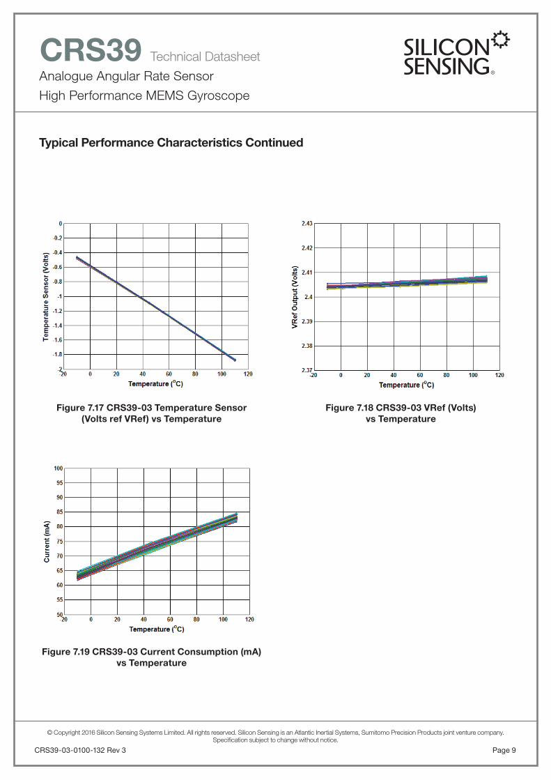
Figure 7.19 CRS39-03 Current Consumption (mA)vs Temperature
Figure 7.17 CRS39-03 Temperature Sensor(Volts ref VRef) vs Temperature
Figure 7.18 CRS39-03 VRef (Volts)vs Temperature
Analogue Angular Rate Sensor
High Performance MEMS Gyroscope
CRS39 Technical Datasheet
INTERNALBUFFERS/FILTERS
RECOMMENDEDCONNECTIONS
1
Vcc+5V (4.9V to 5.25V)+5V
2
GND
3
Rate
4
Ref
5
TMP1
6
TMP2
7
TMP3
8
FRQ
Ground (0V)
(Note 1)
Amplifier
+
-
DifferentialInstrumentationAmplifier
CMOS Schmitt Gate(e.g. 74HC14, TS7S14F)
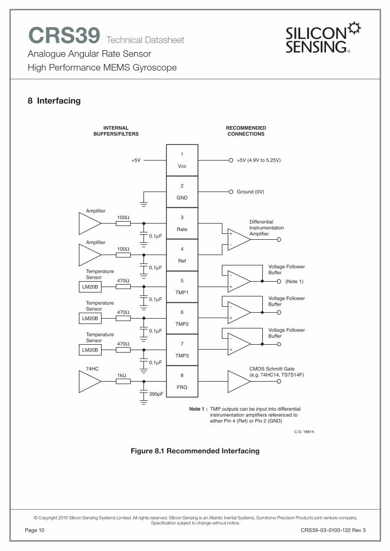
Note 1 : TMP outputs can be input into differential instrumentation amplifiers referenced to either Pin 4 (Ref) or Pin 2 (GND)
Voltage FollowerBuffer
Voltage FollowerBuffer
Voltage FollowerBuffer
100Ω
Amplifier
TemperatureSensor
LM20B
100Ω
470Ω-
+
-
+
-
+
TemperatureSensor
LM20B470Ω
TemperatureSensor
LM20B470Ω
0.1μF
0.1μF
74HC1kΩ
390pF
0.1μF
0.1μF
0.1μF
C.G. 18614
CRS39-03-0100-132 Rev 3Page 10
© Copyright 2016 Silicon Sensing Systems Limited. All rights reserved. Silicon Sensing is an Atlantic Inertial Systems, Sumitomo Precision Products joint venture company.Specifi cation subject to change without notice.
8 Interfacing
Figure 8.1 Recommended Interfacing
Analogue Angular Rate Sensor
High Performance MEMS Gyroscope
CRS39 Technical Datasheet
Page 11CRS39-03-0100-132 Rev 3
© Copyright 2016 Silicon Sensing Systems Limited. All rights reserved. Silicon Sensing is an Atlantic Inertial Systems, Sumitomo Precision Products joint venture company.Specifi cation subject to change without notice.
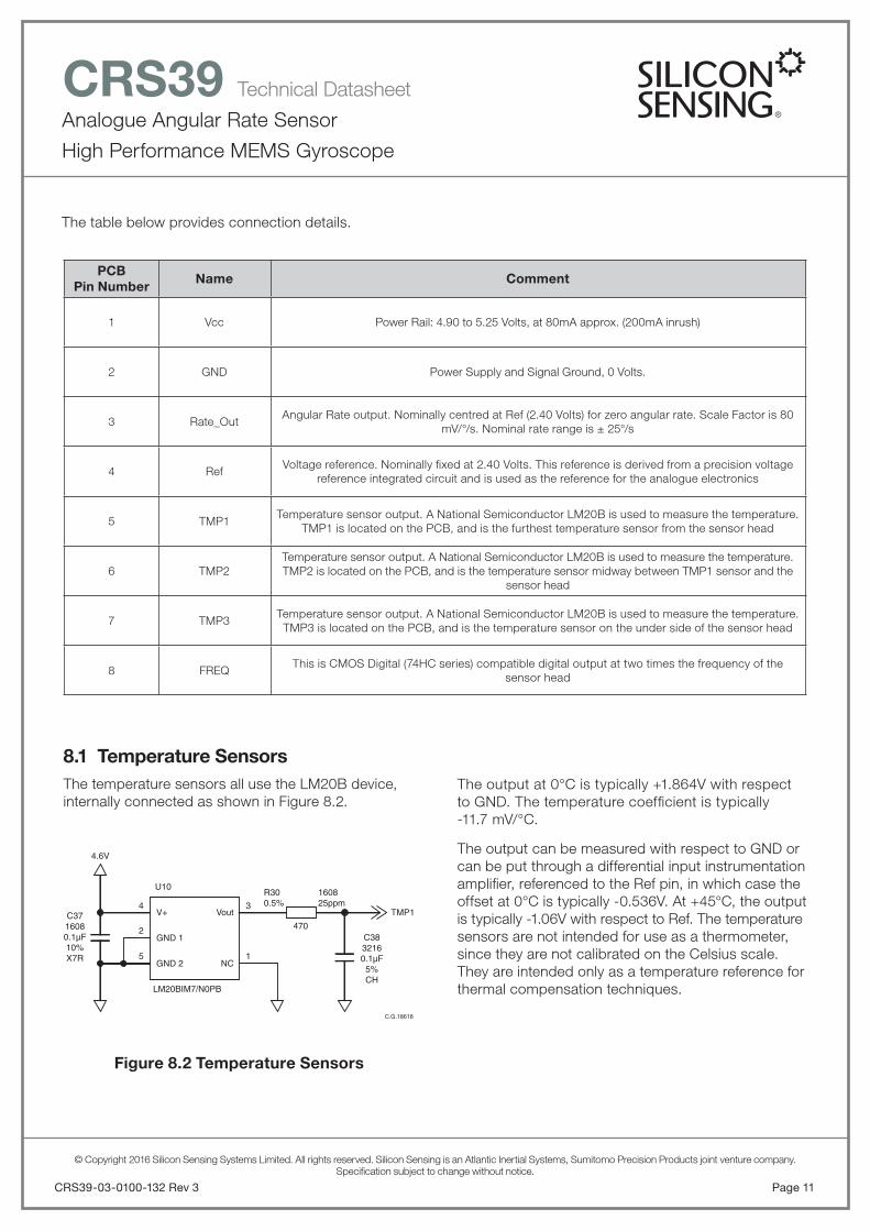
8.1 Temperature SensorsThe temperature sensors all use the LM20B device, internally connected as shown in Figure 8.2.
The output at 0°C is typically +1.864V with respectto GND. The temperature coeffi cient is typically-11.7 mV/°C.
The output can be measured with respect to GND or can be put through a differential input instrumentation amplifi er, referenced to the Ref pin, in which case the offset at 0°C is typically -0.536V. At +45°C, the output is typically -1.06V with respect to Ref. The temperature sensors are not intended for use as a thermometer, since they are not calibrated on the Celsius scale. They are intended only as a temperature reference for thermal compensation techniques.
Figure 8.2 Temperature Sensors
4 3Vout
NC
U10
4.6V
C3716080.1µF10%X7R
C3832160.1µF5%CH
470
TMP1
C.G.18618
V+
GND 1
GND 2
LM20BIM7/N0PB
160825ppm
R300.5%
1
2
5
The table below provides connection details.
PCBPin Number
Name Comment
1 Vcc Power Rail: 4.90 to 5.25 Volts, at 80mA approx. (200mA inrush)
2 GND Power Supply and Signal Ground, 0 Volts.
3 Rate_OutAngular Rate output. Nominally centred at Ref (2.40 Volts) for zero angular rate. Scale Factor is 80
mV/°/s. Nominal rate range is ± 25°/s
4 RefVoltage reference. Nominally fi xed at 2.40 Volts. This reference is derived from a precision voltage
reference integrated circuit and is used as the reference for the analogue electronics
5 TMP1Temperature sensor output. A National Semiconductor LM20B is used to measure the temperature.
TMP1 is located on the PCB, and is the furthest temperature sensor from the sensor head
6 TMP2Temperature sensor output. A National Semiconductor LM20B is used to measure the temperature. TMP2 is located on the PCB, and is the temperature sensor midway between TMP1 sensor and the
sensor head
7 TMP3Temperature sensor output. A National Semiconductor LM20B is used to measure the temperature. TMP3 is located on the PCB, and is the temperature sensor on the under side of the sensor head
8 FREQThis is CMOS Digital (74HC series) compatible digital output at two times the frequency of the
sensor head
Analogue Angular Rate Sensor
High Performance MEMS Gyroscope
CRS39 Technical Datasheet
9 Glossary of Terms
ADC Analogue to Digital Converter
ARW Angular Random Walk
BW Bandwidth
C Celsius or Centigrade
DAC Digital to Analogue Converter
DPH Degrees Per Hour
DPS Degrees Per Second
DRIE Deep Reactive Ion Etch
EMC Electro-Magnetic Compatibility
ESD Electro-Static Damage
F Farads
h Hour
HBM Human Body Model
Hz Hertz, Cycle Per Second
K Kilo
MEMS Micro-Electro Mechanical Systems
mV Mili-Volts
NEC Not Electrically Connected
NL Scale Factor Non-Linearity
PD Primary Drive
PP Primary Pick-Off
RC Resistor and Capacitor fi lter
s Seconds
SF Scale Factor
SMT Surface Mount Technology
SOG Silicon On Glass
SD Secondary Drive
SP Secondary Pick-Off
T.B.A. To Be Announced
T.B.D. To Be Described
Wrt With respect to
V Volts
CRS39-03-0100-132 Rev 3Page 12
© Copyright 2016 Silicon Sensing Systems Limited. All rights reserved. Silicon Sensing is an Atlantic Inertial Systems, Sumitomo Precision Products joint venture company.Specifi cation subject to change without notice.
8.2 Rate and Ref OutputsBoth the Rate and the Ref outputs are passed through a simple RC low pass fi lter before the output pins.The resistor value is 100 ohms. The capacitor valueis 0.1μF.
It is recommended that the Rate Output (signal Highor +) is differentially sensed using a precision instrumentation amplifi er, referenced to the Ref output (signal Low or -).
The Offset of the instrumentation amplifi er should be derived from the host stage (e.g. derived from theADC Ref Voltage) or from the signal ground if the following stage is an analogue stage.
8.3 Frequency OutputsThis is CMOS Digital (74HC series) compatible digital output at two times the frequency of the sensor head. It is provided to give an indication of the temperatureof the MEMS sensor head. The nominal frequency is 28KHz with a typical temperature coeffi cient of-0.8Hz/°C.
The signal is protected with a 1Kohm resistor before being output from the CRS39. It is recommended that this signal is buffered with a CMOS Schmitt Gate such as 74HC12, or TC7S14F. The signal can be used to accurately measure the temperature of the MEMS structure.
An example of measuring the MEMS temperature is to use a precision crystal oscillator (operating at a very high frequency, for example 20, 40 or 60MHz) to measure the frequency of the ring by measuring the time (oscillator clock cycles) to count to a defi ned number of ring cycles.

Analogue Angular Rate Sensor
High Performance MEMS Gyroscope
CRS39 Technical Datasheet
Page 13CRS39-03-0100-132 Rev 3
© Copyright 2016 Silicon Sensing Systems Limited. All rights reserved. Silicon Sensing is an Atlantic Inertial Systems, Sumitomo Precision Products joint venture company.Specifi cation subject to change without notice.
11 Silicon MEMS Ring Sensor (Gyro)At the heart of the CRS39-03 is Silicon Sensing’s VSG3QMAX vibrating ring MEMS sensor which is at the pinnacle of 15 years of design evolution and the latest off a line which has produced over 30 million high integrity MEMS inertial sensors. The VSG3QMAX gyro sensor is combined with precision discrete electronics to achieve high stability and low noise, making the CRS39-03 a viable alternative to Fibre-Optic Gyro (FOG) and Dynamically Tuned Gyro (DTG).
The silicon MEMS ring is 6mm diameter by 100μm thick, fabricated by Silicon Sensing Systems using a DRIE (Deep Reactive Ion Etch) bulk silicon process.The ring is supported in free-space by sixteen pairs of ‘dog-leg’ shaped symmetrical legs which support the ring from the supporting structure on the outside of the ring.
Figure 11.1 Silicon MEMS Ring
The bulk silicon etch process and unique patented ring design enable close tolerance geometrical properties for precise balance and thermal stability and, unlike other MEMS gyros, there are no small gaps to create problems of interference and stiction. These features contribute signifi cantly to CRS39’s bias and scale factor stability over temperature, and vibration immunity. Another advantage of the design is its inherent immunity to acceleration induced rate error, or ‘g-sensitivity’.
C.G. 18619
10 Part MarkingsCRS39-03 is uniquely identifi ed by the part markings onthe SGH03 sensor; the large through-hole metal can device. These markings consist of the following information.
SGH03 Part Number SGH03-11
SGH03 Manufacturing Code 0300000VVXX00YYMMPPWWWCCCCSSS
Content DetailNo ofDigits
Cumulative Digits
0300000VV Product variant 9 9
XX
Relates to the revision level of the product
specifi catione.g. issue 04 = ‘04’
2 11
00 Product variant 2 13
YY
Year - the last two digits of the year of
manufacture 2008 will be shown as ‘08’
2 15
MM
Month - the numerical value of the month of manufacture where:
‘01’ equates to January, and
‘12’ equates to December
2 17
PP
Production Line - at present there is only
one line at SSP, Japan, this will be
denoted as site ‘01’
2 19
WWW
Wafer Lot Number equates to the production lot
number, as defi ned in manufacturing,
consisting of 3 numerical digits
3 22
CCCC
Counter is the series number of the unit
within the production batch, driven by the
sequence off the production line
4 26
SSS Supplier’s internal coding 3 29
The SGH03 Part Number and Manufacturing Code is also stored in the 2D Data Matrix Code printed on the sensor.

Analogue Angular Rate Sensor
High Performance MEMS Gyroscope
CRS39 Technical Datasheet
CRS39-03-0100-132 Rev 3Page 14
© Copyright 2016 Silicon Sensing Systems Limited. All rights reserved. Silicon Sensing is an Atlantic Inertial Systems, Sumitomo Precision Products joint venture company.Specifi cation subject to change without notice.
Figure 11.2 MEMS Sensor Head
The ring is essentially divided into 8 sections with two conductive tracks in each section. These tracks enter and exit the ring on the supporting legs. The silicon ring is bonded to a glass pedestal which in turn is bonded to a glass support base. A magnet, with upper and lower poles, is used to create a strong and uniform magnetic fi eld across the silicon ring. The complete assembly is mounted within a hermetic can with a high internal vacuum.
The tracks along the top of the ring form two pairs of drive tracks and two pairs of pick-off tracks. Each section has two loops to improve drive and pick-off quality.
One pair of diametrically opposed tracking sections, known as the Primary Drive PD section, is used to excite the cos2 mode of vibration on the ring. This is achieved by passing current through the tracking, and because the tracks are within a magnetic fi eld causes motion on the ring. Another pair of diametrically opposed tacking sections is known as the Primary Pick-off PP section is used to measure the amplitude and phase of the vibration on the ring. The Primary Pick-off sections are in the sections 90° to those of the Primary Drive sections. The drive amplitude and frequency is controlled by a precision closed loop electronic architecture with the frequency controlled by a Phase Locked Loop (PLL), operating with a Voltage Controlled Oscillator (VCO), and amplitude controlled with an Automatic Gain Control (AGC) system. The primary loop therefore establishes the vibration on the ring and the closed loop electronics is used to track frequency changes and maintain the optimal amplitude of vibration over temperature and life. The loop is designed to operate at about 14kHz.
Can Lid
Can Base
Upper Pole
Lower PoleC.G. 18620
Support GlassPedestal Glass
Silicon
Magnet
Figure 11.3 Primary Vibration Mode
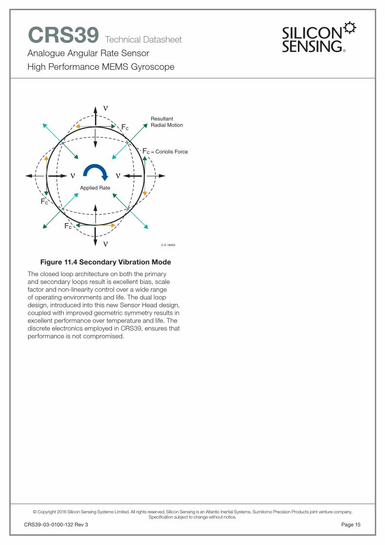
Having established the cos2 mode of vibration on the ring, the ring becomes a Coriolis Vibrating Structure Gyroscope. When the gyroscope is rotated about its sense axis the Coriolis force acts tangentially on the ring, causing motions at 45° displaced from the primary mode of vibration. The amount of motion at this point is directly proportional to the rate of turn applied to the gyroscope. One pair of diametrically opposed tracking sections, known as the Secondary Pick-off SP section, is used to sense the level of this vibration. This is used in a secondary rate nulling loop to apply a signal to another pair of secondary sections, known as the Secondary Drive SD. The current applied to the Secondary Drive to null the secondary mode of vibration is a very accurate measure of the applied angular rate. All of these signals occur at the resonant frequency of the ring. The Secondary Drive signal is demodulated to baseband to give a voltage output directly proportional to the applied rate in free space.
C.G 18623
Zero RadialMotion
at thesepoints
Cos2θVibrationMode at14kHz
ν
ν ν
ν
Analogue Angular Rate Sensor
High Performance MEMS Gyroscope
CRS39 Technical Datasheet
Page 15CRS39-03-0100-132 Rev 3
© Copyright 2016 Silicon Sensing Systems Limited. All rights reserved. Silicon Sensing is an Atlantic Inertial Systems, Sumitomo Precision Products joint venture company.Specifi cation subject to change without notice.
Figure 11.4 Secondary Vibration Mode
The closed loop architecture on both the primary and secondary loops result is excellent bias, scale factor and non-linearity control over a wide range of operating environments and life. The dual loop design, introduced into this new Sensor Head design, coupled with improved geometric symmetry results in excellent performance over temperature and life. The discrete electronics employed in CRS39, ensures that performance is not compromised.
C.G 18400
ResultantRadial Motion
Fc = Coriolis Force
Fc
Fc
Fc
Applied Rate
ν
ν ν
ν

Analogue Angular Rate Sensor
High Performance MEMS Gyroscope
CRS39 Technical Datasheet
© Copyright 2016 Silicon Sensing Systems Limited. All rights reserved. Silicon Sensing is an Atlantic Inertial Systems, Sumitomo Precision Products joint venture company.Specifi cation subject to change without notice.
Specifi cation subject to change without notice.
© Copyright 2016Silicon Sensing Systems LimitedAll rights reserved.
Printed in England 06/2016Date 13/06/2016
CRS39-03-0100-132 Rev 3DCR No. 710011153
Silicon Sensing Systems LimitedClittaford Road SouthwayPlymouth DevonPL6 6DE United Kingdom
T: +44 (0)1752 723330F: +44 (0)1752 723331E: [email protected]: siliconsensing.com
Silicon Sensing Systems Japan Limited1-10 Fuso-ChoAmagasakiHyogo 6600891 Japan
T: +81 (0)6 6489 5868F: +81 (0)6 6489 5919E: [email protected]: siliconsensing.com
CRS39-03-0100-132 Rev 3Page 16
Notes