crud in pwr/vver coolant - ant · pdf filethe importance of an adequate coolant crud control...
TRANSCRIPT
C R U D I N P W R / V V E R C O O L A N T
© October 2015
Advanced Nuclear Technology International
Analysvägen 5, SE-435 33 Mölnlycke
Sweden
www.antinternational.com
CRUD in PWR/VVER Coolant Volume II – Control of CRUD in the PWR/VVER
Coolant and Mitigation Tools
Author
Suat Odar Erlangen, Germany
Reviewed by
Peter Rudling ANT International, Mölnlycke, Sweden

C R U D I N P W R / V V E R C O O L A N T
Copyright © Advanced Nuclear Technology International Europe AB, ANT International, 2015.
I(III)
Disclaimer
The information presented in this report has been compiled and analysed by
Advanced Nuclear Technology International Europe AB (ANT International®)
and its subcontractors. ANT International has exercised due diligence in this work,
but does not warrant the accuracy or completeness of the information.
ANT International does not assume any responsibility for any consequences
as a result of the use of the information for any party, except a warranty
for reasonable technical skill, which is limited to the amount paid for this assignment
by each LCC programme member.

C R U D I N P W R / V V E R C O O L A N T
Copyright © Advanced Nuclear Technology International Europe AB, ANT International, 2015.
II(III)
Contents
1 Introduction 1-1
2 Background Information 2-1
3 Coolant CRUD behaviour 3-1
3.1 Passive oxide layers as CRUD source 3-1 3.2 CRUD release and transportation in PWR/VVER coolant 3-5 3.3 In-core CRUD deposition on fuel assemblies 3-10 3.4 Core CRUD release and radiation field build-up 3-20
4 Preventive tools to minimize CRUD inventory and Radiation fields during plant design phase 4-1
4.1 Selection of steam generator tubing material 4-1 4.2 Steam generator tube manufacturing 4-3 4.3 Cobalt reduction for radiation field control 4-7
4.3.1 Stellite replacement materials 4-8 4.3.2 Control of cobalt content of RCS materials 4-12
4.4 Summary of Section 4 4-16
5 Hot Functional Tests 5-1
5.1 Classical hot functional test for producing passive oxide layers 5-1 5.2 Recent zinc injection for producing passive oxide layers 5-6 5.3 Summary of Section 5 5-9
6 Control of CRUD by Operating Coolant Chemistry 6-1
6.1 Coolant pHT control 6-1 6.1.1 Influence of pHT on CRUD control 6-1 6.1.2 Application at field 6-6
6.2 Zinc injection 6-9 6.2.1 Influence of zinc 6-9 6.2.2 Application at field 6-15 6.2.3 Zinc surveillance programs 6-22 6.2.4 Control of zinc addition 6-26
6.3 Low dissolved hydrogen 6-33 6.3.1 Influence of hydrogen on fuel deposits 6-33 6.3.2 Application at field 6-38
6.4 Use of Enriched Boric Acid (EBA) 6-42 6.4.1 Background information 6-42 6.4.2 Field experience with EBA 6-43 6.4.3 Possible influence of using EBA on AOA 6-45
6.5 Summary of Section 6 6-45
7 CRUD and Radiation Field Control during Plant Shutdown Operations 7-1
7.1 Background information 7-1 7.2 Shutdown chemistry 7-4 7.3 PWR Shutdown Chemistry Guideline recommendations 7-7
7.3.1 EPRI Guideline recommendations 7-7 7.3.2 EdF Shutdown Guideline recommendations 7-8
7.4 PWR shutdown practices 7-11 7.4.1 US PWR plants 7-13 7.4.2 EdF PWR plants 7-14 7.4.3 Siemens designed PWR plants 7-16 7.4.4 Other European PWR plants 7-17 7.4.5 Asian PWR plants 7-23

C R U D I N P W R / V V E R C O O L A N T
Copyright © Advanced Nuclear Technology International Europe AB, ANT International, 2015.
III(III)
7.5 VVER shutdown information 7-25 7.5.1 Loviisa VVER plant in Finland 7-26 7.5.2 VVER plants in Czech and Slovak Republics 7-28 7.5.3 VVER plants in Russia 7-31 7.5.4 VVER plants in Hungary 7-32
7.6 Summary of the Section 7 7-33
8 High-temperature mechanical filtration (VVER-1000 Strategy) 8-1
8.1 Design of the high-temperature filters 8-1 8.2 Field experience 8-3 8.3 Summary of Section 8 8-7
9 Decontamination 9-1
9.1 Background information 9-1 9.2 Chemical decontamination 9-2
9.2.1 General information regarding PWR/VVER industry 9-2 9.2.2 Chemical decontamination processes 9-7 9.2.3 Comparison of chemical decontamination technologies 9-15 9.2.4 Recontamination post decontamination 9-19 9.2.5 VVER decontamination experience 9-23
9.3 Mechanical decontamination 9-25 9.3.1 Sivablast process 9-25 9.3.2 Application at CANDU HPWR plants 9-26
9.4 Summary for Section 9 9-29
10 Fuel CRUD removal 10-1
10.1 Ultrasonic fuel cleaning 10-1 10.1.1 Background information 10-1 10.1.2 High Efficiency Ultrasonic Fuel Cleaning (HE-UFC) system 10-8
10.2 Chemical decontamination 10-11 10.2.1 Background information 10-11 10.2.2 Incident at Paks Unit 2 10-13 10.2.3 Root cause and lessons learned 10-17
10.3 Summary of Section 10 10-18
11 Conclusive summary and recommendations 11-1
11.1 Preventive tools to minimize CRUD inventory and radiation fields during plant design phase 11-1
11.2 Hot functional tests 11-2 11.3 Control of CRUD by operating coolant chemistry 11-2 11.4 CRUD and radiation field control during plant shutdown operations 11-5 11.5 High-temperature mechanical filtration (VVER-1000 strategy) 11-8 11.6 Decontamination 11-9 11.7 Fuel CRUD removal 11-10
12 References 12-1
Nomenclature
Unit conversion

C R U D I N P W R / V V E R C O O L A N T
Copyright © Advanced Nuclear Technology International Europe AB, ANT International, 2015.
1-1(1-2)
1 Introduction As explained in Volume I of this STR, according to anecdotes the acronym “CRUD” stays for the term “Chalk River Unidentified Deposits”, where first time in the PWR industrial history some deposits on the fuel assemblies in the research reactor of the Chalk River Laboratories of AECL was observed. Since then this term is frequently used by PWR industry only for the corrosion products in the reactor coolant system. For the corrosion products in the feed-water or in the secondary side of the steam generators this term is not used.
The importance of an adequate coolant CRUD control (i.e. stable oxide layers to protect the structural material integrity, which produces the CRUD, and minimizing the core deposits) to achieve improved plant performance was already recognized at the beginning of PWR operations in1960s. Accordingly, since then lot of investigations were performed and are still on going to understand the stability behaviour of oxide layers in the reactor system as well as the complex function of their release, transport and in-core deposition.
ANT International published a Special Topic Report (STR) entitled: “CRUD in PWR/VVER and BWR Primary Circuits” in the LCC2 programme in 2006, which summarized the information available till end of 2005. Since 2005, significant plant experience was gained especially with respect to fuel deposits. In the Volume I of this two-volume report (issued in LCC10 programme) up-dated insight into different types of phenomena was provided, like solubility, transportation, deposition and release of CRUD that helps to better understand the CRUD behaviour under PWR/VVER operating conditions. The published up-dated information including the CANDU field experience was summarized and evaluated with emphasis to practical aspects of the PWR/VVER operation.
The purpose of the Volume II of this report is to describe the tools and their application to adequately control the coolant CRUD in order to improve the fuel and out-core radiation performance. Its content is given in the following:
• Background information (Section 2) describing the importance and meaning of the coolant CRUD control;
• Coolant CRUD behaviour (Section 3) summarizes the information given in the volume I with the objective to enable the readers for better understanding the application of the mitigation tools for CRUD control without reading the Volume I report;
• Preventive tools to minimize CRUD inventory and Radiation fields during plant design phase (Section 4) summarises the laboratory investigation results as possible tools to improve the passive oxide layers with the objective to reduce the CRUD source term;
• Hot functional test (Section 5) that describes the chemistry procedures to be applied during the hot functional tests to improve the passive oxide layers with the objective to reduce the CRUD source term;
• Control of the coolant CRUD during power operation (Section 6) that describes the possible coolant chemistry programs to improve the coolant CRUD control;
• CRUD and radiation field control during plant shutdown operations (Section 7), which describes the chemistry praxis to mitigate the shutdown chemistry release from the core area;
• High temperature mechanical filtration (Section 8), describes the field experience of the mechanical filtration technology applied during the power operation in VVER 1000 plants;
• Decontamination (Section 9) summarizes the chemical and mechanical CRUD removal from the reactor coolant system and/or from its components;

C R U D I N P W R / V V E R C O O L A N T
Copyright © Advanced Nuclear Technology International Europe AB, ANT International, 2015.
1-2(1-2)
• Fuel CRUD removal (Section 10), describes the CRUD deposit removal processes from the core to improve fuel operational performance;
• Conclusive summary (Section 11), concludes finally the information given in the Volume II of this two-volume report.
The information given in the Volume II report:
• Can support the plant chemists to establish their coolant chemistry strategy to achieve the plant specific goals with respect to coolant CRUD control.
• In addition the information given in this report is also valuable for fuel vendors and plant fuel engineers to evaluate the possible ways of improving the fuel performance. In a similar way, this information helps the Regulators at properly examining the relative importance of various CRUD Control Mitigating Tools to ensuring an improved fuel performance for safe operation.

C R U D I N P W R / V V E R C O O L A N T
Copyright © Advanced Nuclear Technology International Europe AB, ANT International, 2015.
2-1(2-2)
2 Background Information All materials used in nuclear power plants are, as bare material (steels and/or alloys), are not stable in the reactor water and dissolve by corrosion. They are protected by passive oxide layers formed by the corrosion attack of the water under operating conditions. The protective effect of these oxide layers is based on their low solubility in the water. However, to some small extend these oxide layers dissolve in the reactor coolant and are transported as corrosion products (called also CRUD) to the reactor core. There they deposit on the fuel assemblies and are activated. The deposition of the CRUD on fuel assemblies and their release to coolant influences highly the core and plant performance with respect to fuel cladding integrity and radiation fields. Based on more than 50 years of PWR/VVER industry experience an inadequate coolant CRUD control can result in serious plant problems not only in-core problems like enhanced fuel cladding corrosion, pressure (and reactivity) drop across the core, AOA occurrence; but also out-of-core high radiation fields. The main PWR performance problems caused and/or influenced by CRUD are:
• Primary Water Stress Corrosion Cracking (PWSCC) of nickel based alloys in in-core and/or out-core areas, which occurs by degradation of protective oxide layers under tensile stresses at high temperatures;
• High out-core radiation fields due to deposited activated CRUD that cause exposure of the plant staff and maintenance personnel to ionizing radiation;
• Heavy fuel deposits, leading to higher fuel cladding temperatures due to increased thermal resistance, which may cause enhanced fuel cladding corrosion, pressure (and reactivity) drop across the core, and Axial Offset Anomaly (AOA) generation, which is also called Chemistry Induced Power Shift (CIPS).
The importance of an adequate coolant CRUD control, i.e. stable oxide layers to protect the material integrity and minimizing the core deposits, to achieve improved plant performance was already recognized at the beginning of PWR operations in1960s. Accordingly, since then lot of effort was done to understand the stability behaviour of oxide layers in the reactor system as well as the complex function of their release, transport and in-core deposition. Based on achieved experience coolant chemistry was modified continuously to address the needs of adequate CRUD control. However, the economical demands force the PWR industry to increase the core duty using more enriched uranium and/or MOX fuel assemblies for longer fuel cycles. This core duty evolution is some how in contradiction to the demands of coolant chemistry for adequate CRUD control and makes extremely difficult to achieve the coolant chemistry goals. Therefore, it is essential to understand the CRUD behaviour at different locations with changing chemistry conditions (pHT and Redox Potential) around the non-isothermal Reactor Coolant System for tailoring the coolant chemistry program plant specific to achieve at least acceptable results of CRUD control. All these CRUD behaviour and its characteristics are explained in detail in Volume I of this report.
“Adequate CRUD Control” means actually minimization of the CRUD deposits on fuel assemblies, which can be achieved by
• Improving the passive oxide layers (i.e. inner oxide layers) on the surfaces of the structural materials so that less corrosion products are released from the outer oxide layers into reactor coolant that are transported to core area (source term reduction) and,
• Counteracting the CRUD deposition mechanism by increasing the CRUD solubility across the reactor core by selection of adequate coolant chemistry program and finally if necessary
• Applying mechanical and/or chemical fuel cleaning technologies.

C R U D I N P W R / V V E R C O O L A N T
Copyright © Advanced Nuclear Technology International Europe AB, ANT International, 2015.
2-2(2-2)
All these measures applied for the “CRUD Control” improve the fuel performance and plant radiation fields. However, among all these the improvement of the passive oxide layers on the steam generator tubing material might be the important mitigation tool. Because the steam generator tubing with highest surface area of about 70–75% of the total RCS surfaces is the major source for the coolant CRUD. Therefore, a reduction of the metal release rates from these surfaces results in source term reduction and hence has the highest contribution to adequate coolant CRUD control. This oxide layer improvement can be and is done in many periods of the lifetime of the PWR and VVER plants, even as preventive measure starting before the construction of the plants. These are:
• Selection of the contractual materials of the reactor coolant system,
• The manufacturing of the steam generator tubes by using adequate manufacturing process,
• Hot functional tests during construction and commissioning of the plants, and finally
• Power operation by applying adequate coolant chemistry.
In the following Sections of the Volume II of this report the application of the all possible mechanical and/or chemical tools are explained that can be performed starting with selection of reactor coolant system materials and during steam generator tube manufacturing and then after during different plant operation modes, such as commissioning (Hot Functional Tests), plant shutdown and power operation, to achieve adequate CRUD control with the objective to mitigate and/or avoid the problems that are caused or induced by coolant CRUD. However, for better understanding of the explanation of these tools a brief summary of the coolant CRUD behaviour that is discussed in detail in Volume I of this report will be given first in the following Section 3.

C R U D I N P W R / V V E R C O O L A N T
Copyright © Advanced Nuclear Technology International Europe AB, ANT International, 2015.
3-1(3-31)
3 Coolant CRUD behaviour In this Section a brief summary of the coolant CRUD behaviour that was described in the Volume I of this report is given, with the aim to enable the reader for better understanding the available tools to achieve an adequate CRUD control.
3.1 Passive oxide layers as CRUD source Under PWR operational conditions oxide layers build-up on the structural materials (stainless steels, nickel- and/or iron-based alloys) that protects the materials against corrosion. These oxide layers are consisting of duplex oxide layers, an inner oxide layer and overlying outer oxide layer (see Figure 3-1). Actually the inner oxide layer consists of two sub-layers: “Internal” or “barrier” layer with chemical composition of Cr2O3; and a chromium rich “intermediate” layer of mixed spinel oxides so called chromites. The “external layer” or former so-called “outer-oxide layer” has the chemical composition of spinel-type nickel ferrites and this layer is on stainless steels almost chromium free (<5% Cr) and on nickel-based alloys completely chromium free.
Figure 3-1: Schematic illustration of oxide film growth by ion transportation through the oxide layers, after [Combrade et al, 2005] and [Bojinov et al, 2002].
The Cr2O3 “internal” or “barrier” layer, which is built on the steels and/or alloys surfaces having ≥10% chromium, has extremely thin thickness of few nm. The Cr2O3 internal layer is formed very rapidly on the bare surface and its thickness increases with the Cr content of the alloy. It is believed that this Cr2O3 internal layer is actually the real protective passive layer. Therefore, for achieving adequate coolant CRUD control, actually this “barrier” layer needs to be improved; so that it prevents or slow-downs the nickel and/or iron metal ion transport from base metal to outer oxide layers, where they are released to coolant by dissolution under the PWR/VVER operating coolant reducing conditions.
C R U D I N P W R / V V E R C O O L A N T
Copyright © Advanced Nuclear Technology International Europe AB, ANT International, 2015.
3-2(3-31)
As shown in Figure 3-1, the inner oxide layer (or intermediate layer) grows at the metal/oxide interface as the water penetrates through the crystal defects such as pores and cracks in the oxide layer to the metal surface, where it reacts with the metal ions to build oxides. It grows mainly by anion mass transport towards the oxide/metal interface although there is clearly iron and nickel cation transport in the reverse direction. The driving force for this metal cation diffusion is the metal ion concentration difference between the metal surface and the coolant. However, the different chemical behaviour of the metal ions (iron, nickel and chromium) influences their diffusion behaviour across the inner oxide layers: In contrast to iron and nickel, chromium has smaller diffusion rate as trivalent cation (Cr3+) compared to divalent cations (Fe2+ and Ni2+) and builds extremely insoluble Cr2O3 compound. Hence, chromium that is released from alloy surface builds immediately Cr2O3 layers, whereas iron and nickel can diffuse further towards oxide/coolant interface. Subsequently still unbound chromium can build, because of its higher thermodynamically stability, iron- and/or nickel-chromites on Cr2O3 barrier layer. Therefore, the inner part of the protective oxide layer becomes chromium-rich, whereas the outer part is iron and nickel-rich and almost free of chromium (see Figure 3-2). Overall thickness of the inner oxide layer varies with the surface conditions of the steels and/or alloys; and can be up to several nano-meters. Such different surface conditions are “as received”, electro-polished and mechanically polished.
Figure 3-2: TEM cross-sectional image of the oxide film formed on AISI 361 SS and Alloy 600 under simulated PWR operating coolant conditions at 320°C for 380 and 1730 hours respectively [Terachi et al, 2008].

C R U D I N P W R / V V E R C O O L A N T
Copyright © Advanced Nuclear Technology International Europe AB, ANT International, 2015.
3-3(3-31)
The outer oxide layer is a result of the interaction between the reactor coolant and the oxide layers; like solubility and precipitation of the corrosion products. The thickness of the outer oxide layer depends on the chemical conditions of the coolant such as redox potential and coolant nickel and iron concentrations; and also on the cation permeability behaviour of the inner oxide layers. It forms only in coolant saturated by corrosion products (nickel and iron) due to high solubility of the iron and nickel in spinels under reduced alkaline PWR coolant conditions (see Figure 3-3). In iron-saturated coolant, large crystals of iron/nickel spinel oxide usually exist in this outer oxide layers that are produced by precipitation of corrosion products from the saturated coolant. Usually these outer oxide layers are thicker than the inner oxide layers. However, in the case of existing dense inner oxide layers (e.g. with zinc addition from the beginning on) these outer oxide layers are much thinner than the inner oxide layers as confirmed at the field. The chemical composition of these outer-oxide layers consists of a mixture of iron and nickel spinel oxides. The nickel content of this oxide layers depends on the steam generator tubing material that is used (see Table 3-1 for the chemical composition of the SG tubing materials).
Figure 3-3: Iron, nickel and chromium solubility at 300°C and neutral pH from thermodynamic calculations, after [Ahlberg & Rebensdorff, 1992].
Table 3-1: Main components of the nickel- and iron-based alloys and stainless steel used as SG tubing materials in PWR and VVER plants.
SG tubing material Ni [%] Cr [%] Fe [%] Ni/Fe Ratio
Alloy 600 MA/TT >72 14–17 6–10 7–12
Alloy 690 TT >58 27–31 7–11 8–5
Alloy 800 NG 30-35 19–23 42–51 0.6–0.8
Alloy 18-10Ti* 10–11.5 17–19 69.5–73 0.13–0.16
* VVER SG tubing material (stainless steel) ANT International, 2014

C R U D I N P W R / V V E R C O O L A N T
Copyright © Advanced Nuclear Technology International Europe AB, ANT International, 2015.
3-4(3-31)
In the case of VVER plants with stainless steel steam generator tubing, the nickel content of the outer oxide layers is very low; it can be described as magnetite that contains some nickel. If iron base Alloy 800 is used the outer oxide layers consist of nickel ferrites without excess nickel. In the case of nickel base steam generator tubing materials like Alloy 600 and Alloy 690, the nickel content is very high with Ni/Fe ratio >0.5 than that of nickel ferrites. In this case excess nickel exists as metallic nickel in addition to nickel ferrites in the outer-oxide layers. The outer-oxide layers have no protective behaviour for the structural materials. They are in equilibrium with the reactor coolant saturated by corrosion products and depending on the CRUD concentration of the coolant, which may change due to operational events, either they release corrosion products to coolant or corrosion products precipitate on the outer oxide layers. Accordingly they contribute highly to fuel deposits and in turn to out-of-core radiation build-up. The outer oxide layer has direct contact with the reactor coolant and in contrast to inner oxide layer, serves almost alone as CRUD source for the fuel deposits. The chemical composition of the fuel deposits (see Table 3-2) that have insignificant amount of chromium indicates that inner oxide layers do not contribute significantly to CRUD transportation to core area. Therefore, for adequate coolant CRUD control, excess growth of these outer oxide layers needs to be counteracted by improving the inner oxide layers that reduces the iron and nickel transport from the base metal to outer oxide layers (source term reduction).
Table 3-2: Fuel CRUD elemental composition in Westinghouse plants per 1986 (10 plants during 1–3 cycles, after [Polley & Pick, 1986].
Element Composition Range
Iron 68±7% 57–80%
Nickel 29±6% 19–38%
Chromium 3±2% 1–6%
Cobalt 0.2±0.2% 0.03–0.5% ANT International, 2014
The outer oxide layer is clearly influenced by coolant environment and its outer most layer is covered with hydroxyl groups by coolant hydration. The hydroxyl groups form by dissociation of the adsorbed H2O molecules and chemisorption of the dissociated protons (H+ ions) on oxygen atoms in the neighbourhood. These surface hydroxyl groups are ampholytes being able to acid dissociation and/or to proton receiving thus creating negative and/or positive surface charges depending on coolant pH values. At pH values where the surface has no charges the point of pH value is called “Point of Zero Charge” (PZC).

C R U D I N P W R / V V E R C O O L A N T
Copyright © Advanced Nuclear Technology International Europe AB, ANT International, 2015.
3-5(3-31)
Figure 3-4: (a): Cross section of the outer most oxide layer on the RCS structural material: 1): Surface metal ions show low coordination (e.g. in dry form); 2): In coolant surface metal ions coordinate H2O molecules; 3): Dissociative chemisorption of H2O molecules leads to hydroxylated surfaces, after [Schindler, 1981]. (b): Origin of the surface charge on oxide films on metal surfaces, after [Hettiarachchi, 2013].
This oxide surface charges and the resulting Zeta potential are responsible for the adsorption of the charged coolant ingredients (corrosion products as soluble cations and/or as colloids) on the outer oxide layers. With respect to electrostatic interaction there exists repulsive forces between the surfaces with same charges and attraction between surfaces with opposite charges.
Incorporation of zinc in spinel oxide layers stabilizes the spinels, which results in reduction in source term of corrosion products.
3.2 CRUD release and transportation in PWR/VVER coolant
The solubility of the spinel oxide films is actually very low and they protect the materials very well. Accordingly, the associated metal ion release is extremely low and their concentrations in the reactor coolant are in trace levels (e.g. iron in the range of few µg/kg; nickel by factor 5-10 lower than iron, usually less than 1 µg/kg; and cobalt significantly lower than the nickel). Even so, at the liquid-oxide interface some metal oxide does dissolve mainly from the outer oxide layers and are transported by coolant flow to the core area, where they precipitate by boiling and/or due to their decreased solubility by increasing temperature.
Metal release and corrosion rates of different steam generator tubing materials and of a stainless steel including their nickel release data are given as comparison in Figure 3-5.

C R U D I N P W R / V V E R C O O L A N T
Copyright © Advanced Nuclear Technology International Europe AB, ANT International, 2015.
3-6(3-31)
Figure 3-5: Comparison of corrosion and metal release rates of Alloy 600, Alloy 690, Alloy 800 and stainless steel 304 SS, after [Riess & Odar, 2011].
Steam generator tubing has the largest surface area; hence, they are the main sources for the coolant corrosion products by metal release. However, this metal release and precipitation mechanism occur on both in-core and out-core surfaces. Due to boiling on the fuel rod surfaces the CRUD deposition in the core area is more significant than on the steam generator tube surfaces. The subsequent release of the dissolved activated corrosion products from core can re-precipitate on out-of-core surfaces and thereby build radiation fields.
The metal release rate of all PWR structural materials with fresh surfaces is at the beginning high, which decreases with a time of exposure to the coolant after several fuel cycles due to growth of protective oxide layers. This behaviour was also observed in old PWR plants after installing new replacement components such as steam generators and/or reactor pressure vessel head. A schematic illustration of the radiation field evolution during the lifetime of PWR plants as a result of metal release is shown in Figure 3-6. Manufacturing processes and/or surface conditions of the structural materials can also influence the metal release rate significantly, as it was confirmed by replacement steam generators at the field and not only by laboratory testing. Figure 3-7 illustrates good example of nickel and 58Co release during plant shutdown operations experienced with replacement steam generators manufactured by different manufactures at US PWR plants.

C R U D I N P W R / V V E R C O O L A N T
Copyright © Advanced Nuclear Technology International Europe AB, ANT International, 2015.
3-7(3-31)
ANT International, 2012
mSv
/h
0
20
40
60
80
100
120
0 2 4 6 8 10 12 14 16 18 20 22
Metal release
Dose-rate development
Activation ofthe Inventory
SGR VHR
Cycle #
1
2
3
mg/d
m2 x
mo
Figure 3-6: Schematically illustration of a general scenario for activity build-up, after [Riess & Odar, 2011].
Figure 3-7: Cumulative probability distribution of long-term shutdown nickel and 58Co release rates separated by tube manufacturer, after [Marks et al, 2012].
Metal release behaviour of stainless steels and nickel- and/or iron-base alloys can also be positively influenced by zinc addition to reactor coolant (see Figure 3-8). Zinc incorporation in the spinel oxide layers stabilizes the oxide layers that result in drastically reduction of structural material corrosion and release rates. However, for the long term reduction of the coolant corrosion product source term continuous zinc injection is necessary. It is important to mention that the introduction of zinc injection in older PWR plants results usually in increase of corrosion product release at the beginning for several fuel cycles, because zinc replaces these corrosion product cations from the spinel oxides by incorporation. For long term this enhanced metal release decreases due to decreased source term of corrosion products.
C R U D I N P W R / V V E R C O O L A N T
Copyright © Advanced Nuclear Technology International Europe AB, ANT International, 2015.
3-8(3-31)
Figure 3-8: Metal corrosion and metal release rates with and without zinc addition, after [Esposito et al, 1991].
The circulating coolant corrosion products consist of soluble, particulate and colloidal species of different size in diameter. Usually, particulate species having less than 1 µm diameter size is called colloids. However, based on the use of micro pore filters of 0.45 µm size for filterable coolant corrosion products in the PWR plants, all species that have diameter size bigger than 0.45 µm are called “suspended particles”; and all species with size diameters smaller than 0.45 µm are defined as soluble corrosion products in the PWR industry. The detailed field investigations with the use of micro pore filters of different size down to 10 nm (0.01 µm) revealed that this so-called soluble fraction actually consists of colloids with up to tiny size in diameters even smaller than 0.01 µm. In the fraction of colloidal corrosion products with diameters smaller than 0.01 µm size it was found that small part of them are in real soluble form with a content of in ng/kg (ppt) range!
The plant observations confirm that the particulate corrosion products with diameter size bigger than 1 µm are usually mechanically released from surface deposits, mainly from core area by control rod movements, during the power change or shutdown operations. Even though the coolant mass concentration of this bigger size particulate CRUD might be relatively large due to their higher mass, their numerical particle concentration is small during the steady state power operation. An increase in their concentration was experienced usually during shutdown operations or during sudden power changes. Based on detailed plant investigations, during the undisturbed power operation the majority of the circulating coolant corrosion products (>90%) are in colloidal form with diameter size of less than 200 nm (0.2 µm). Their origin is the solubility of the outer oxide layers on the structural materials and/or nucleation in the reactor coolant that is saturated by corrosion products.
All these particulate and colloidal corrosion products have surface charges and zeta potential (see Figure 3-9a) due to hydroxide groups formed in the coolant by hydration, similar to the outer oxide layers on the structural materials. This surface charges and zeta potential, which depends on the coolant pHT values, are responsible for their interactions on the outer oxide layers and in the circulating coolant with other species (see Figure 3-9b). Especially the colloidal corrosion products with small size diameter (<200 nm) that have the highest population in the coolant are the major carrier of the radio-cobalts due to their higher surface areas.

C R U D I N P W R / V V E R C O O L A N T
Copyright © Advanced Nuclear Technology International Europe AB, ANT International, 2015.
3-9(3-31)
Figure 3-9: (a): A schematic of electrical double layer generation around a colloidal particle and showing the origin of the zeta (ζ) potential, (b): Charge titration curves for two surfaces (CRUD particles and oxide layers on pipe surfaces) having different Points of Zero Charges (PZC), after [Hettiarachchi, 2013].
Reactor coolant is saturated by corrosion products and is in equilibrium with the huge outer-oxide layers on the structural materials and with the fuel CRUD deposits in the core area. During the undisturbed steady state power operation the coolant corrosion product concentration is relatively constant. In case of some operational actions such as power change that cause increase in coolant CRUD concentration due to release of corrosion products or during make-up water injection that results in decrease of coolant CRUD concentration by dilution this equilibrium is disturbed. However, based on field experience quick response of the system takes place to compensate this disturbance by precipitation of coolant CRUD on outer-oxide surfaces or release of corrosion products from there. An example of the influence of make-up water injection on coolant CRUD concentration dilution and its subsequent make-up by release of corrosion products from the outer oxide layers on the RCS surfaces is shown in Figure 3-10.
Figure 3-10: Influence of make-up water injection on coolant corrosion product concentration, after [Bolz et al, 1996].
Based on plant observations, the purification rate of CVCS is too slow to reduce the increased coolant concentration of the particulate corrosion products caused by transient CRUD release; usually they are removed from the coolant mainly by re-deposition on the surfaces rather than by CVCS purification.

C R U D I N P W R / V V E R C O O L A N T
Copyright © Advanced Nuclear Technology International Europe AB, ANT International, 2015.
3-10(3-31)
An indication was also observed during the detail measurements at Belgian PWR plants with nickel base Alloy 600 steam generator tubing material that the corrosion product particles of bigger size growth with the plant age at cost of particles of smaller size.
3.3 In-core CRUD deposition on fuel assemblies The reactor core is a very efficient filter to collect the circulating coolant corrosion products. This results in a continuous release of corrosion products from the outer oxide layers to compensate the corrosion product removal by fuel assemblies due to equilibrium between the reactor coolant and the outer-oxide layers on the structural material surfaces.
Since the earliest PWR operating experience in 1960s it is known that corrosion products in the coolant are depositing on the irradiated heat-transfer surfaces in the core area on the fuel rod surfaces. The corrosion product deposition on the fuel rods is driven by boiling on the fuel surfaces and the CRUD mass is proportional to the degree of Sub-cooled Nucleate Boiling (SNB), which is the main driving force for the deposition. Since SNB does not occur until the upper spans of the fuel assembly surfaces, CRUD deposit is typically heavier in spans 5 and 6, where boiling occurs (see Figure 3-12). In the following a simplified deposition mechanism is illustrated (see Figure 3-11).
Figure 3-11: Fuel deposits: (a): Formation of deposits according to Tentative Boiling Model; (b): Principle of Wick boiling, after [Iwahori et al, 1979] and [Pan et al, 1985] respectively.

C R U D I N P W R / V V E R C O O L A N T
Copyright © Advanced Nuclear Technology International Europe AB, ANT International, 2015.
3-11(3-31)
Due to Wick-boiling the fuel CRUD deposits contain usually lot of steam chimneys (see Figure 3-12). These steam chimney pores enhance the heat transfer from the fuel rod surfaces into coolant and thus reduces drastically the thermal resistance of the CRUD layer. Due to these pores, the fuel deposits are porous with less density and high voidage. The estimated density of the PWR fuel deposits is in the range of 1.2 g/cm3. In the case of thin deposits with many boiling chimneys, which provides excellent cooling of the fuel clad surfaces, the cladding surface temperatures do not exceed much above the coolant saturation temperature in the reactor core. This cooling effect of the Wick boiling in the thin deposits is extremely beneficial not only with respect to cladding corrosion but also regarding the concentration of chemical additives and impurities beneath the fuel deposits.
Figure 3-12: Simplified illustration of PWR fuel assembly temperature profile and corrosion product deposits [Odar, 2012a]. (Figure redrawn using the figures from [Bergmann et al, 1985] and [Bengtsson et al, 2008]); including the High magnification SEM of a CRUD flake obtained from Span 6B from Vogtle-2, Cycle 8 [EPRI, 2004c].
In many PWR plants, especially with high duty cores, it was observed that a transfer of fuel CRUD takes place from the older once and/or twice burned fuel assemblies to fresh introduced feed fuels assemblies (see Figure 3-13). This is due to the migration of boiling from once and/or twice burned fuel assemblies that contains some CRUD on their surfaces to the boiling of feed fuel results in a natural feedback loop for CRUD. Therefore, in case of heavy fuel deposits it is extremely important to remove these deposits from once/twice burned fuel assemblies in high duty cores before starting new fuel cycle in order to avoid possible AOA problems.

C R U D I N P W R / V V E R C O O L A N T
Copyright © Advanced Nuclear Technology International Europe AB, ANT International, 2015.
4-1(4-16)
4 Preventive tools to minimize CRUD inventory and Radiation fields during plant design phase
4.1 Selection of steam generator tubing material As in detail already discussed in Volume I of this STR and summarized in previous Section 3 of this Volume II, duplex oxide layers are normally built under PWR, VVER and CANDU coolant operating conditions. Both oxide layers have spinel structure, the inner layer being a regular spinel (chromites) and the outer layer an inverse spinel (ferrites). From these duplex oxide layer the inner oxide layer with its Barrier layer is the protective layer, whereas the outer oxide layers is the only one that stays in interaction equilibrium with the reactor coolant and thus as CRUD source only responsible for the metal release to the coolant. The chemical composition of these oxide spinels depends on the chemical composition of materials exposed to the reactor coolant. As structural materials nickel- and/or iron-based alloys are used for the steam generator tubes; and for the rest of the reactor coolant system components (Reactor Pressure Vessel, Pressurizer and Main Coolant Pumps) and loop piping mainly stainless steels are used. Regarding the coolant CRUD control only steam generator tubing material having the highest surface area is important among all these RCS components. All other stainless steel components and loop piping have total surface area of about 5% of the total RCS surfaces accordingly they can be considered as minor CRUD sources.
For all reactor types the highest surface area has the steam generator tubing with above 70% of the total surface area. Accordingly, steam generator tubing material is dominating the chemical composition of the reactor coolant CRUD as main source and influences highly the fuel deposit characteristics and behaviour (see Section 3). The steam generator tubing materials used in different reactor types like PWR, VVER and CANDU plants and their surface areas are given in Table 4-1. The chemical composition of these different steam generator tubing materials is given Table 4-2. The chemical composition of the oxide layers that grow on the surfaces of the steam generator tube surfaces depends on the chemical composition of the tubing material. In case of nickel-based alloys (Alloy 600, Alloy 690) and/or iron-based alloy (Alloy 800), which are used as steam generator tubing material in PWR and CANDU plants, the nickel content of the oxide layers are higher than in VVER plants using stainless steels for their steam generator tubes, because of higher nickel content of these alloys (see Table 4-2) with Ni/Fe ratios in the range of 7–12 for Alloy 600 and 5–8 for Alloy 690. If compared with the Ni/Fe ratios of nickel ferrites (0.5–1) experienced in PWR surface oxide layers; this indicates a nickel excess of these alloys. Accordingly, if nickel-base alloy is used for the SG tubing, in that case the outer oxide layers on out-of-core surfaces usually contain besides nickel ferrites also metallic nickel under reducing coolant conditions. Hence this excess nickel is also transported to core area where it deposits on fuel-clad surfaces. On fuel assembly rods, nickel exists in metallic form only in the lower part of the core, whereas in the upper part, where due to higher temperatures boiling is expected, nickel exists usually as nickel oxide deposit (see Section 3). This excess nickel, especially nickel oxide, in the fuel deposits is the main source of the CRUD induced problems such as densification of the fuel deposits resulting in enhanced cladding corrosion and/or AOA phenomenon due to densification of the fuel deposits (NiO has about 80% more volume compared to metallic nickel), and in increased radiation fields caused by 58Co and high 58Co release during shutdown operations.
In contrast to nickel-base alloys, iron-base Alloy 800 has Ni/Fe ratio in the range of 0.6–0.8, which corresponds well to the nickel ferrite composition. Accordingly the PWR plants with Alloy 800 SG tubing have the composition of iron chromites as inner oxide layer and nickel ferrites as outer oxide layer without having excess nickel. This results in less nickel content in the fuel deposits, as expected and confirmed by field experience.

C R U D I N P W R / V V E R C O O L A N T
Copyright © Advanced Nuclear Technology International Europe AB, ANT International, 2015.
4-2(4-16)
Keeping in mind the problems caused in the primary side of the PWR plants by excess nickel in the fuel deposits, Alloy 800 would be the best selection for the steam generator of the PWR and CANDU plants. Unfortunately, the discussion about the most suitable steam generator tubing material was determined by the steam generator Secondary Side problems. Even though, Alloy 800 has also now more than 45 years of excellent Secondary Side performance, due to demanding influence of US PWR industry and EPRI a new Alloy 690TT was developed and which is selected by most of the PWR Utilities for their replacement steam generators.
Table 4-1: Estimated relative surface areas of reactor materials in PWR, CANDU, after [Berry & Diegle, 1979] and VVER plants (calculated by author from data given in [Yurmanov et al, 1997]).
Reactor Type Components Material Relative Surface Area
PWR
Steam Generator Alloy 600, Alloy 690 and Alloy 800
70–75%
Fuel Cladding Zry-4, Zirlo, M5 20–25%
Loop pipe work, Pressure Vessel, Pressurizer, Main Coolant Pump
Stainless Steels ∼5%
CANDU (PHWR)
Steam Generator Monel 400*, Alloy 600 or Alloy 800
∼77%
Fuel Cladding Zircaloy 4 ∼13%
Loop pipe work, Pressure Vessel, Pressurizer, Main Coolant Pump
Carbon Steel ∼10%
VVER 440/1000
Steam Generator Stainless Steel ∼77%/∼72%
Fuel Cladding Zirconium 1% Niobium ∼20%/∼21%
Loop pipe work, Pressure Vessel, Pressurizer, Main Coolant Pump
Stainless Steel ∼3%/∼7%
* Monel 400 is used only in oldest CANDU plants ANT International, 2015
Table 4-2: Main components of the nickel- and iron-based alloys and stainless steel used as SG tubing materials in PWR and VVER plants.
SG tubing material Ni [%] Cr [%] Fe [%] Ni/Fe Ratio
Alloy 600 MA/TT >72 14–17 6–10 7–12
Alloy 690 TT >58 27–31 7–11 8–5
Alloy 800 NG 30–35 19–23 42–51 0.6–0.8
Alloy 18-10Ti* 10–11.5 17–19 69.5–73 0.13–0.16
* VVER SG tubing material (stainless steel) ANT International, 2015

C R U D I N P W R / V V E R C O O L A N T
Copyright © Advanced Nuclear Technology International Europe AB, ANT International, 2015.
4-3(4-16)
In the following Section the improvements with respect to CRUD control, which can be achieved by adequate tube manufacturing processes will be explained. This information might be important especially for the new PWR plant owners that have decided to select steam generators with Alloy 690TT tubes or for the owners of the older plants that decided to purchase replacement steam generators with Alloy 690TT tubing.
4.2 Steam generator tube manufacturing Based on the PWR field experience and also laboratory investigations using industrial steam generator tubing materials it is known that the manufacturing processes have significant influence on metal release rate of the tubes under operating conditions. Due to need for huge number of replacement steam generators in the 1990s, lot of laboratory investigations were performed worldwide, mainly in France, USA and Japan, to optimize the manufacturing processes with the aim to reduce the metal release rates of the steam generator tubing materials. Most of these investigations were performed with Alloy 690TT that was used mostly for replacement steam generators. These investigations revealed that, the manufacturing processes, such as techniques of pilger-rolling and/or drawing for tube manufacturing, atmosphere of treatment, surface cleaning treatments, and last thermal treatment at about 700°C, has significant impact on the formation of the geometrical, metallurgical and physico-chemical state of the alloy surface layers, which in turn influence the formation and the growth and also the properties of the oxide layers formed on alloy surfaces. For example, the French investigations revealed that the tube samples with highest metal release rate had cloud of chromium carbides in their grains (up to 60 µm) and small grains at the alloy surface with surface pollutions by aluminium particles. In contrast to this, the tube samples with low metal release behaviour had homogeneous grain size throughout the whole tube sample without any small grains at the alloy surface, pollution by aluminium was at low-level; and there were no visible chromium carbides in the grains (see Figure 4-1) [Clauzel et al, 2010].
Figure 4-1: Correlation between the surface properties of the Alloy 690 and their metal release behaviour [Clauzel et al, 2010].
Different tube manufacturing processes can result in different metal release rate of the same tubing Alloy as it was confirmed by laboratory testing (see Figure 4-2).
C R U D I N P W R / V V E R C O O L A N T
Copyright © Advanced Nuclear Technology International Europe AB, ANT International, 2015.
4-4(4-16)
Figure 4-2: Metal release kinetics of tested industrial Alloy 690 tubes in simulated PWR coolant conditions at 325°C, after [Carrette et al, 2006].
Same results were also confirmed by nickel and 58Co release rate at field, which is a measure for the metal release rate from steam generator tubes, experienced during plant shutdown operations at PWR plants having Alloy 690TT steam generator tubing from different manufacturers (see Figure 4-3).
Figure 4-3: Comparison of cumulative nickel released (normalized by SG tube surface area) vs. EFPY for different trends with time, after [Marks et al, 2012].
Based on these worldwide investigations the tube manufacturers have successively improved also their manufacturing processes, which are mainly consists of:
• Suppression of sand blasting the SG tubes by corundum particles,
• Annealing only under H2 atmosphere, instead of NH3 + H2 atmosphere like in the past,

C R U D I N P W R / V V E R C O O L A N T
Copyright © Advanced Nuclear Technology International Europe AB, ANT International, 2015.
4-14(4-16)
Top View
Rod Cluster Control
Top Nozzle304 L Stainless SteelSpringsInconel 718
Control Rod304 L Stainless SteelClad
Fuel CladdingZry-4/M5, ZIRLO,DUPLEX
SpacersZry-4/M5/ZIRLOInconel 625
Bottom Nozzle304 L Stainless SteelDebris Filter304 L Stainless Steel
Bottom View
Top SpacerZry-4/Inconel 625
Guide TubeInstrument TubeZry-4/M5/ZIRLO
Bottom SpacerZry-4/Inconel 625
ANT International, 2007
Figure 4-10: PWR fuel assembly with Alloy 718 spacer grids.
The Borssele staff’s observations prompted Westinghouse first review differences in the channel head dose rate trends for Westinghouse-designed PWRs that had changed from Inconel to Zircaloy grids within the first four cycles of operation (D. C. Cook 1, Prairie Island 1 and 2, and Kewaunee) and others that either did not change from Inconel to Zircaloy grids or changed in later cycles (Beznau 1 and 2, Beaver Valley 1, Farley 1, Indian Point 2, and North Anna 2). Westinghouse reported that channel head dose rates for the first group of plants levelled out at 5 to 7 R/hr, while the comparable steady-state values for the second group were about a factor of three higher. Then after, with the available evidence from Borssele, an investigation was undertaken to estimate the cobalt impurity concentration that could have been present in the nickel plating used to fabricate Inconel fuel grids manufactured by Westinghouse. This study showed that the cobalt concentration in the nickel plating could have ranged from 0.04 to 1.3% for grid spacers fabricated from the late 1960s to early 1978. This confirms the similar experience with fuel manufacturing was done worldwide.
The Ringhals data are of interest with respect to high radiation field increase caused by high cobalt impurity concentration in nickel brazed Inconel spacer grids, since they reflect plants that have had varying sources of cobalt progressively as follows:

C R U D I N P W R / V V E R C O O L A N T
Copyright © Advanced Nuclear Technology International Europe AB, ANT International, 2015.
5-1(5-9)
5 Hot Functional Tests Hot Functional Tests (HFT) are the tests that are performed during the commissioning of the nuclear power plants to check if the plant systems are operating according to their design criteria. These tests are performed in several stages, which may differ for different plants depending on detailed plant design criteria and plant vendor experience. During these HFTs the structural material surfaces of the reactor coolant system are exposed first time to high-temperature water. Accordingly, in nuclear industry it is believed that the HFT during the plant commissioning is being of crucial importance to its subsequent operational performance and behaviour in view of the need to minimize radiation fields and the dose to the operators and to the general public and finally because of the potential vulnerability of the steam generators to tube degradation processes. For these reasons, a so-called “Passivation” process is integrated in these HFTs with the aim to produce adequate passive oxide layers on the surfaces of structural materials that protects the materials against corrosion and reduces the metal release rates. In the following sections the chemistry of this passivation process is described.
5.1 Classical hot functional test for producing passive oxide layers
In general, the HFTs are applied in several stages due to their purpose of testing the operability of the plant systems under their designed operating conditions. Usually in the first stage, called also HFT1, the plant systems are tested without core (fuel) loaded in the Reactor Pressure Vessel, by heating up the Reactor Coolant System (RCS) by Main Coolant Pumps (MCP). During the HFT1 there is no need to inject boric acid and hydrogen gas into RCS due to absence of core in the RPV; on the other side, usually plant commissioning management don’t want to inject potential hazardous chemicals before successful testing the leak tightness and function capability of the plant system and components. During the subsequent HFT2 and further HFT stages the functional tests are performed at designed operating temperature with core loaded in the RPV starting with criticality and progressive power escalations. In these HFT stages boric acid and hydrogen gas are injected into RCS and functionality of the injection systems are proven. Some plant vendors commissioning team combines the tests for proof of the functionality of boric acid and hydrogen injection system with HFT1 by injecting these chemicals after confirmation of the RCS leak tightness at the end of HFT1 without having core in the RPV.
Because the HFT1 is the first time where the surfaces of the RCS structural materials are exposed to high-temperature water, the “Passivation” process is integrated in this HFT1. The coolant chemistry recommendations for the Passivation Process during the HFT1 are aimed at producing an adequate passive oxide film on the internal surfaces of the RCS, which would minimize the release of corrosion products during subsequent power operation. Reducing corrosion product release rates resulting in reduced deposition in-core, activation to radionuclides especially such as 58Co and 60Co that cause out-of-core radiation fields and Occupational Radiological Exposure (ORE).
The only chemistry program, which found a broader basis within the plant vendors for the application of passivation during HFT, is the establishment of slightly alkaline and reducing conditions. The chemistry specifications from different plant vendors to be applied during the HFT for surface passivation are given in Table 5-1, Table 5-2 and Table 5-3.

C R U D I N P W R / V V E R C O O L A N T
Copyright © Advanced Nuclear Technology International Europe AB, ANT International, 2015.
5-2(5-9)
Table 5-1: Water chemistry specifications for HFT of Siemens designed PWR plants.
Parameter Limit Remarks
Duration [hrs] >50 In practice extended up to 6 weeks due to length of HFT
Temperature [°C] >260 Effective at >290°C
Oxygen [µg/kg] <5 By N2H4 injection and/or by Degasification system
Lithium [mg/kg] 1–2 pH25: 9–10
Chloride [µg/kg] <200
∑ Corrosion products [µg/kg] <100 ANT International, 2015
In most HFTs, alkaline conditions have been obtained using natural lithium hydroxide that contains 7.5% 6Li. However, 6Li is a significant source of tritium during power operation and it was, therefore, considered that the use of natural lithium during HFT could lead to a risk of some lithium hydroxide being trapped in dead legs, with the consequent risk of increased tritium production during the first fuel cycle. Therefore, to avoid this risk, Siemens use only lithium-7 hydroxide for HFTs that also used at some Westinghouse PWR plants during HFTs.
The time duration of the passivation step is specified from > 50 hours (e.g. Siemens) up to 240 hours (e.g. EdF) or even up to 4 weeks (672 hours) by Westinghouse. However, according to some field data evaluation results the time duration of the HFTs should not have significant influence on coolant CRUD behaviour during the subsequent power operation of several fuel cycles [Garbett, 1994] and [Cubitt et al, 2004].
Table 5-2: Westinghouse specifications and guidelines for Reactor Fluid Systems during Hydrostatic and Hot Functional Prestartup Testing, after [Garbett, 1994].
Specification Parameters Value
Lithium(a) [mg/kg] 1–2
Chloride(b) [µg/kg] ≤150
Fluoride(b) [µg/kg] ≤150
Oxygen(c) [µg/kg] ≤100
Guideline Parameters Value
pH at 77°F (30°C) Variable
Silica [µg/kg], max prior to boration 200
Boron [mg/kg], if BTRS*) testing performed 0–2000
RCS passivation requires at least 4 weeks total exposure at temperatures above 500°F (260°C) prior to core loading. Target for system passivation is met when suspended solids concentration is less than 100 µg/kg (d)
(a): The specified lithium concentration must be established prior to heat-up beyond 150°F (65°C). Lithium is used in the form of lithium hydroxide (b): Halogen concentrations must be maintained below the specification values at all times. (c): During prestartup testing, dissolved oxygen must be controlled to less than 100 µg/kg whenever the reactor temperature is above 180°F (82°C). (d): Solids concentration determine by filtration through a filter having 0.45 µ pore size, or by nephelometry. *): BTRS is Boron Thermal Regeneration System
ANT International, 2015

C R U D I N P W R / V V E R C O O L A N T
Copyright © Advanced Nuclear Technology International Europe AB, ANT International, 2015.
5-3(5-9)
Table 5-3: VVER water chemistry specifications for hot functional testing, after [Zmitko et al, 2004].
Parameter Limit Remarks
pH25C 5.6–7.5 Before KOH dosing
pH25C 9–10.5 After KOH dosing
pH300C 6.9–7.5 After KOH dosing
Chloride and Floride [mg/kg] <0.1
Potassium [mg/kg] 2–5 After KOH dosing
Oxygen [mg/kg] <0.02 At >120°C
Silica (SiO2) [mg/kg] <0.2
Suspended solids [mg/kg] <0.2
Dissolved hydrogen [Nml/kg] 2–5 Expected level ANT International, 2015
End of 1980s and beginning of 1990s information published by Japanese PWR industry suggested that preconditioning during HFT in the presence of hydrogen was beneficial with respect to metal release rates for Alloy 600 and Alloy 690TT. According to their investigation, the metal release rates for Alloy 600 and Alloy 690TT under PWR operating conditions are reduced if the preconditioning during HFTs is performed in a lithium hydroxide/hydrogen medium. Based on this information, at Sizewell B a modified HFT chemistry was adopted using hydrogen injection in addition to lithium hydroxide [Cubitt et al, 2004]. The modification differed the Sizewell B HFTs conditions from Westinghouse HFT recommendation given in Table 5-2. The detailed information regarding the plant parameters and chemistry specifications are given in Table 5-4:

C R U D I N P W R / V V E R C O O L A N T
Copyright © Advanced Nuclear Technology International Europe AB, ANT International, 2015.
6-1(6-48)
6 Control of CRUD by Operating Coolant Chemistry
With respect to coolant CRUD control, the mechanism of the operating coolant chemistry serves two ways by:
1) Improving the passive oxide layers on the surfaces of the structural materials of the Reactor Coolant System; thus reducing the metal release rates, which results in reduced fuel deposits. This mechanism is called “Source Term Reduction”. This can be achieved by selecting adequately high alkalinity under reducing conditions; and/or by zinc injection.
2) Reducing the residence (retention) time of the CRUD in the core area by increasing the solubility of the corrosion products with increasing temperature across the core in axial direction. This again can be achieved mainly by selecting an adequate coolant pHT values for the entire fuel cycle. In addition, a remarkable influence of coolant dissolved hydrogen concentration on reduction of nickel content of the fuel deposits has been also experienced. This is especially important for the PWR plants having steam generators with nickel base Alloys (600 MA/TT and/or 690TT) and operating with high duty cores; particularly due to AOA risk, which is affected by excess nickel in the fuel deposits.
To achieve these goals coolant chemistry has three mitigating tools that are applied during power operation for coolant CRUD control. These are the Coolant pHT values, zinc injection and finally the Coolant Dissolved Hydrogen concentration. In the following sections brief description of their mechanism as background information will be given und their application at field is explained.
6.1 Coolant pHT control
6.1.1 Influence of pHT on CRUD control
Importance of the reactor coolant alkalization and of the operating pHT value of the PWR coolant was recognized during early PWR operation in the 1960s. Lot of in-core problems caused by CRUD deposits on fuel assemblies, such as pressure drop across the core, loss of core reactivity, were experienced due to insufficient pHT values and/or operation without alkalization. Especially, among all these problems, the influence of alkalinity on reactor reactivity was very important due to its safety issue:
During the demonstration program regarding the feasibility of using boric acid for chemical shim at Saxton PWR plant, it was observed that there was loss of core reactivity with decreasing coolant pH. As the coolant pH was increased, there was regain of this reactivity. Figure 6-1 shows the change of core reactivity with coolant pH at Saxton PWR plant [Weisman & Bartnoff, 1965]. During this test, pH was decreased by lithium removal caused by putting the CVCS cation exchange resin filter into service over a period of about 12 hours. During this period with low pH in the coolant, a loss of reactivity was observed (indicated by temperature decrease), with the maximum effect achieved in about 24 hours after termination of lithium removal. The increase of reactivity following subsequent lithium addition was quicker. Similar experience gained at Saxton PWR plant was also observed at Yankee, Indian Point I and BR-3 PWR plants. Because of its potential relationship to the safety of PWR plant operation; this so-called “pH-Effect on Reactor Reactivity” was investigated in great detail. As a result of this investigation study, it was found that the core reactivity loss was due to increase in fuel temperature caused by fuel deposits, which had handicapped the thermal heat transfer from the fuel to the coolant. Fuel deposition is favoured at low pH values while increase in coolant pH value favours the corrosion product dissolution. Hence, the reactivity lost could be re-gained by pH increase.

C R U D I N P W R / V V E R C O O L A N T
Copyright © Advanced Nuclear Technology International Europe AB, ANT International, 2015.
6-2(6-48)
All these experiences regarding fuel deposition gained during early PWR operation in 1960s confirmed that alkalization of coolant is crucial for safe and reliable PWR operation. Therefore, this subject was investigated in detail by Westinghouse in 1960s. As a result of these investigations Lithium/Boric Acid chemistry under reducing conditions is born for PWR operation, which was continuously improved up to present based on the needs.
Figure 6-1: Change of reactivity with coolant pH at Saxton, 20 MW PWR plant, after [Weisman & Bartnoff, 1965].
Lithium-7-hydroxide is injected for the alkalinisation of the coolant that contains boric acid as chemical shim. In the first step, lithium hydroxide was added to the coolant adjusting the lithium concentration between 1–2 mg/kg. This so-called “1–2 ppm lithium chemistry” had no pH strategy but just to alkalinize the boric acid solution to avoid heavy fuel deposits and to mitigate the radiation fields. Even though this coolant alkalization was able to avoid heavy fuel deposits; it was not satisfactory with respect to radiation field build-up. The positive influence of the coolant pHT increase on the radiation field build-up was recognized in the 1960s and 1970s at field. Thus, the pHT increase program was introduced and improved worldwide stepwise according to the needs caused by core duty increase due to economic reasons. The lithium/pHT control strategies that were developed and introduced stepwise since early 1980s up to present are summarized schematically in Figure 6-2.

C R U D I N P W R / V V E R C O O L A N T
Copyright © Advanced Nuclear Technology International Europe AB, ANT International, 2015.
6-3(6-48)
Figure 6-2: Coolant chemistry lithium/pHT strategies developed and used worldwide to optimize the radiation field control [Odar, 2011].
The improvements of coolant chemistry with respect to lithium/pHT control started in the mid of 1970s–early 1980s with “Classical Coordinated Chemistry” that had the objective to control the coolant pH300 constant at 6.9. This pH300 of 6.9 was selected based on magnetite solubility behaviour that has its solubility minimum at pH300 6.9. Based on field data evaluation the change from “1–2 ppm lithium Chemistry” to “Classical Coordinated Chemistry” resulted in dose rate reduction of about 18% at plants with nickel base alloy steam generator tubes [EPRI, 2004c]. After it was found that the reactor coolant system surface oxide layers has nickel ferrite composition rather than magnetite, several PWR plants have changed their coolant chemistry to so-called “Elevated Lithium Chemistry” with higher lithium concentration of 3.5 mg/kg, which considers the minimum solubility of nickel ferrites at pH300 of 7.4. The plants with Alloy 600 steam generator tubes that applied this chemistry have experienced a dose rad reduction of ~25% compared to “Classical Coordinated Chemistry” [EPRI, 2004c].
Even though, this Elevated Lithium Chemistry regime was very successful in reducing the dose rates (see Figure 6-3) it was terminated at the beginning of 1990s due to concerns of PWSCC in SG Alloy 600MA tubes that may be caused by longer exposure of this material to higher lithium concentration. Therefore, so-called “Modified Chemistry” was introduced in 1990s for the PWR plants operating with longer fuel cycles, which has the target pH300 of 7.4 and considers the lithium concentration limits (~2.1 mg/kg) given by fuel vendors due to fuel cladding corrosion concerns. This chemistry regime allows with approval of fuel vendors, depending on fuel cycle length, a lithium concentration of >2.2 to <3.5 mg/kg (for a short time) at the beginning of cycle (BOC), in order to avoid pHT of <6.9, which was experienced to be detrimental for radiation control. The modified chemistry applied at Siemens-KWU designed PWR plants differs slightly from this modified chemistry described above by limiting the BOC lithium concentration to 2.1 mg/kg. This is because these plants are operating with 12 months fuel cycles with BOC boron concentration of about 1200 mg/kg that doesn’t require to increase the BOC lithium concentration above 2.1 mg/kg. For those Siemens designed PWR plants this modified chemistry was very successful with respect to minimize the out-of-core radiation fields (see Figure 6-4). Also, based on an evaluation of field results it was confirmed that the introduction of Modified Chemistry resulted in dose rate reductions of 15–25% in US PWR plants with Alloy 600 steam generator tubes [EPRI, 2004c].

C R U D I N P W R / V V E R C O O L A N T
Copyright © Advanced Nuclear Technology International Europe AB, ANT International, 2015.
7-1(7-35)
7 CRUD and Radiation Field Control during Plant Shutdown Operations
Worldwide within PWR industry it is believed that Shutdown Chemistry Procedure is one of the most important and powerful coolant chemistry tools for control of Coolant CRUD, Fuel Deposits and out-of-core Radiation fields. Due to this knowledge, worldwide excessive investigations and studies were performed in order to gain compressive experience. Accordingly, great emphasis is given in this Section for the Shutdown Chemistry.
7.1 Background information In contrast to steady state power operation, a cold shutdown causes significant changes of the physico-chemical conditions in total reactor coolant system especially in the core area. Four major steps are causing these changes of conditions:
• Power reduction
• Boration of the system
• Temperature decrease equivalent to a pH decrease
• Oxygenation (H2O2 injection; applied mainly in PWRs with nickel base alloy SG tubes)
All these changes in reactor coolant conditions cause significant activated CRUD release from the fuel assembly deposits that can have impacting on shutdown dose rates or particulate contamination levels in the reactor coolant system. Typical plant shutdown process and associated CRUD release results experienced in an EdF PWR plants is illustrated in Figure 7-1 and Figure 7-2.
Figure 7-1: Typical parameters of a cold shutdown in an EdF PWR plant, after [Daquait et al, 2002].

C R U D I N P W R / V V E R C O O L A N T
Copyright © Advanced Nuclear Technology International Europe AB, ANT International, 2015.
7-2(7-35)
Figure 7-2: Total activity in the RCS during cold shutdown in an EdF PWR plant, after [Daquait et al, 2002].
CRUD release can be seen, during all operational steps of shutdown, such like power reduction (due to control rod movements and decrease in core duty, which is the driving force for CRUD deposition), and actions that increase the CRUD solubility such as boration of the reactor coolant system, temperature decrease and typically the maximum release during the forced oxygenation step.
Two major issues need to be considered in the case of heavy fuel deposits, which lead to significant amount of corrosion product release:
• The time for clean-up for radio-nuclides, mainly 58Co and 60Co, will delay the reactor pressure vessel head removal and thus extend the total time of the refuelling outage,
• Contamination of the out-of-core surfaces may increase the personnel radiation exposure during the annual outage maintenance work.
The major goal of the shutdown chemistry procedure is to prepare the plant for a refuelling or mid-cycle outage in a time as short as possible without negatively impacting the outage activities with respect to dose rates and/or particulate contamination levels. This depends on the fuel CRUD loading and composition, which is influenced by the core duty and the steam generator tubing material. The PWR plants with high duty cores that have nickel base alloys for steam generator tubes, especially in the case of Alloy 600, have usually nickel rich heavy fuel deposits. If Alloy 690 instead of Alloy 600 is used as steam generator tubing material, again nickel rich however less fuel CRUD deposits can be expected. The PWR plants having iron base Alloy 800 steam generator tubes don’t have excess nickel in their fuel CRUD deposits; and the CRUD deposit amount is very few, even for high duty cores. The VVER plants with stainless steel steam generator tubes have usually few fuel CRUD deposits with some exceptions, which were influenced by previous chemical decontaminations of the steam generators. The fuel CRUD deposits of VVER plants consist usually of some nickel containing magnetite spinel and they don’t have any excess nickel. Because of these differences from plant to plant, the shutdown chemistry procedures to achieve the goals of shutdown operation without or at least less radiation problems in a time as quick as possible are also plant specific, which is explained in detail in the following Sections.

C R U D I N P W R / V V E R C O O L A N T
Copyright © Advanced Nuclear Technology International Europe AB, ANT International, 2015.
8-1(8-8)
8 High-temperature mechanical filtration (VVER-1000 Strategy)
8.1 Design of the high-temperature filters The High Temperature Filtration (HTF) System (TC or SVO-1) with titanium sponge filter equipment has been implemented at all standard VVER-1000 V320 design plants operating in Ukraine, Russia, Bulgaria and Czech Republic since mid 1980s. Four SVO-1 systems (each a HTF and Cather Filter) were used located across the Main Coolant Pumps (MCP) at each Reactor Coolant System loop (see Figure 8-1). The coolant flow through the HTF is driven by the pressure difference developed over the MCPs. The principle and objectives for filtration of the primary coolant particles in VVER has been described by Kysela in the Section 3.2 of the ANTI STR, “Operational Issues and Practices”, issued under LCC7 [Nordmann et al, 2011].
Figure 8-1: Principle diagram of the VVER-1000 primary coolant high temperature filtration system (SVO-1); (a): Cross section of the HTF equipment; (b): Connection of HTF and Catcher Filter to RCS [Yurmanov et al, 2008].
The SVO-1 Coolant Cleaning Circuit is continuously in service during the power operation. It is disconnected only during RCS failures, annual outages with inspections and in the case of MCP failures. The main operating parameters of the SVO-1 system are given in Table 8-1.
There are two regeneration methods for these filters: the backwash rinsing or the chemical cleaning:
• Backwash rinsing: At the end of the operation cycle, the filters are drained, backwashed and rinsed with a pressurized air and water mixture. This procedure takes place in each cycle after the refuelling.

C R U D I N P W R / V V E R C O O L A N T
Copyright © Advanced Nuclear Technology International Europe AB, ANT International, 2015.
8-2(8-8)
• Chemical cleaning: Each SVO1 system has a separated container for sorbent washing. Sorbent can be moved to this container in order to use alkali and acid cleaning solutions. After this treatment and water rinsing, the sorbent is moved back.
Table 8-1: Main operating parameters of the High Temperature Filtration SVO-1 system, after [Nordmann et al, 2011].
Operating parameters Values
Pressure 160 bar
Temperature 290°C
Linear flow velocity (linear filtration rate) 100 m/h
Flow rate 100 m3/h
Pressure drop (empty filter) 0.1 bar (without filter)
Pressure drop (filled filter) 4 bar (with filter)
Height (height of titanium filter) 820 mm
Pressure drop of particle catcher 0.3 bar
Volume of the titanium sponges in the filter 0.7 t ANT International, 2015
Operating parameters of coolant loops can show significant differences between each other such as pressure drop on each SVO1 system observed at Temeline VVER plant (Figure 8-2). The first and the third filter pressure drop are slightly increasing with the time on the contrary to the second and the fourth SVO1 systems.
Figure 8-2: Pressure drop on high-temperature filters measured at Temelin VVER plant.

C R U D I N P W R / V V E R C O O L A N T
Copyright © Advanced Nuclear Technology International Europe AB, ANT International, 2015.
8-3(8-8)
8.2 Field experience The HFT (SVO-1) circuit was implemented into RCS of the VVER-1000 plants with the intention to remove fine particulate corrosion products from the coolant in order to reduce CRUD deposition on RCS surfaces and accordingly to reduce the radiation exposure of plant personnel. The criterion of the SVO-1 system was to fulfil the water chemistry requirements of the OST 95 962-82 Standard “Primary Circuit Coolant of VVER-1000 NPP – Technical Requirements for Maintaining Water Quality”, which prescribes a maximum reactor coolant iron concentration of 200 µg/kg, [Luzanova & Zadonskij, 1990]. However, as during power operation the coolant contains mainly colloidal corrosion products with particle size much less than µm and only very small amount consists of particulate corrosion products. Accordingly, these filters can mainly be effective during start-up and shutdown operations.
The filtration efficiency can be described as a relation between the concentration of the particles on the filter inlet and the inlet – outlet concentration ratio. A ratio of 1 means no cleaning and the results <1 represents particles releasing. Efficiency data from Zaporozhe VVER 1000 plant (Ukraine) are shown in Figure 8-3. As it can be seen, the high temperature filter efficiency depends on the inlet corrosion product concentration; and the purification (K>1) takes place above some concentration threshold, [Gorbatenko et al, 2005].
Figure 8-3: High temperature filter efficiency depending on the inlet corrosion product (iron) concentration at Zaporozhe, after [Gorbatenko et al, 2005].
Up to now, there exist more than 20 years of field experience on efficiency of the HTF (SVO-1) system from VVER-1000 plants; however, the published field results are inconsistent. Whereas the HFT effectiveness of CRUD removal was confirmed, based on measurements during Hot Functional Tests at Kozloduy Unit 6 plant [Dinov, 1991] and in some VVER-1000 plants (with HTF coolant iron concentration almost in an order of magnitude less than in VVER units without HTF reported), opposite information was also published by Zaporozhe Units based on their detailed survey [Dobrovolska & Arkhypenko, 2007] and [Martykan, 2010], as described in the following:
C R U D I N P W R / V V E R C O O L A N T
Copyright © Advanced Nuclear Technology International Europe AB, ANT International, 2015.
9-1(9-30)
9 Decontamination
9.1 Background information Decontamination is an optional countermeasure against activity build-up on inner surfaces of the reactor systems. The application of decontamination techniques to reactor components, equipment, and systems is essential for reducing occupational exposures, limiting potential releases and uptakes of radioactive materials, permitting the reuse of components, and facilitating waste management. Decontamination processes are carried out during operation, service breaks and in decommissioning of a Nuclear Power Plant (NPP). The decision to decontaminate should be weighed against the total dose and cost. Especially at the component level the benefits of decontamination and of a replacement with a new component have to be carefully evaluated. Decontamination methods have been developed for a number of years for different types of reactors. Practically two main ways to decontaminate exist: mechanical and chemical/ electro-chemical. The selection of the decontamination process in the in-situ case depends on the achievable Decontamination Factor (DF), the material compatibility and the amount of waste that will be generated. Mechanical decontamination is usually applied to single components and includes tens of different techniques. Chemical decontamination, on the other hand, has been applied on both component and system level decontaminations (electrochemical decontamination mainly for components). Chemical decontamination processes are also numerous but during the years a few techniques have turned out to be more applicable than the others. Both ways to decontaminate have gone through a massive development work during the years and also totally new techniques and processes are developed all the time.
In this Section different decontamination techniques are briefly described summarising the studies presented in numerous reports and scientific publications over the last thirty years. The main goal has been to build-up an awareness of the many decontamination processes and techniques used in nuclear industry during the last decades. The purpose of this work has not been to rank the techniques but to collect the descriptions of the most used techniques and to identify their characteristics. Due to the huge amount of data about different decontamination processes and applications presented in literature, the study has been limited mainly to describe processes for use in subsystem/component operational decontamination. Therefore, for example waste management issues and economical aspects related to each technique have not been included in this survey.
Decontamination means removal of radionuclides from the inner surfaces of primary coolant loop or its components in NPPs. On a wider scale decontamination also means removal of oxide layers from material surfaces e.g. in process plants. However, in process industry the more used term for oxide removal is mechanical or chemical cleaning instead of decontamination. In this work decontamination is evaluated only for nuclear environments.
The target for decontamination can be either components (e.g. main coolant pump), a subsystem (e.g. residual heat removal system) or a full system, (e.g. whole PWR and/or VVER plant with or loop without fuel). For the components that can be easily removed from the system the most usual option is to use either mechanical or electrochemical decontamination, whereas in all other cases the chemical decontamination is the only viable method. The selection of a proper decontamination technique must be based on several selection criteria that have been established to rationalise this selection. The criteria are briefly described in following sections.

C R U D I N P W R / V V E R C O O L A N T
Copyright © Advanced Nuclear Technology International Europe AB, ANT International, 2015.
9-2(9-30)
A reason for developing the decontamination technology has been: Starting in 1969, all commercial NPPs were required to submit radiation exposure data for all personnel to the Authorities. These data were published annually e.g. by the US Nuclear Regulatory Commission (NRC) and are easily available to the general public. From 1969 to the early 1980s, the total annual collective exposure increased rapidly but the average dose per worker remained essentially constant. This meant that many more workers were being exposed each year.
Apart from the physiological concerns with such rapidly increasing cumulative exposure, there was also the practical concern of whether there would be a large enough pool of workers to service NPPs in the future if such trends continued. Thus, there was considerable pressure on the nuclear industry to reduce radiation exposure. The dose per worker can be reduced by using more workers to perform a particular job, but detailed audits have shown that this tends to increase the collective dose, exactly the opposite of what is desired. Since any effects of the exposure to the group as a whole are proportional to the collective dose, this procedure has no net benefit and in fact is detrimental. The only way to benefit the group as a whole is to reduce the collective dose. This conclusion is based on the experience of the nuclear community, regarding occupational radiation exposure. In the early days there was a steep increase in the radiation field followed till today by a lowering of these values.
In 1971 the International Committee on Radiation Protection (ICRP) recommended to limit the radiation dose and to implement radiation protection methods. This was the start of many regulations issued by the various Authorities. As a consequence e.g. the terms As Low As Possible (ALAP) and As Low As Reasonably Achievable (ALARA) became guidelines.
In the following sections the decontamination processes are explained, which are available and applied worldwide to reduce the radiation fields in PWR and VVER plants as preparation for the repair and maintenance work that are performed during the annual refuelling outages in order to reduce the radiation exposure of the maintenance personnel. The information given is based on the content of the ANT International STR “Decontamination and Steam generator Chemical Cleaning” issued for LCC5 programme in 2009/2010, [Riess et al, 2009].
9.2 Chemical decontamination
9.2.1 General information regarding PWR/VVER industry
In early PWR operating years before 1970s only some few chemical decontamination work was performed at PWR Test Reactors in USA using mainly concentrated chemical processes. The PWR industry was confident that decontamination work would not be required in the lifetime of the commercial operating PWR plants. This situation changed rapidly at the mid of 1970s due to need for intensive inspection, repair and maintenance work on steam generators and/or Main Coolant Pumps. Accordingly, intensive investigations were performed for the development of the dilute chemistry processes, in order to address the utility concerns regarding the chemical decontamination applications, such as:
• Material compatibility and corrosion performance,
• Possible formation and precipitation of insoluble compounds during the decontamination,
• High radio-active waste volumes that may be produced by decontamination processes,
• Recontamination of the reactor coolant system and/or components in subsequent fuel cycles after decontamination.
As a result of these worldwide research studies several dilute chemical decontamination processes were developed in different countries as follows:

C R U D I N P W R / V V E R C O O L A N T
Copyright © Advanced Nuclear Technology International Europe AB, ANT International, 2015.
9-3(9-30)
• AECL in Canada has developed the Canadian Decontamination Process (CAN-DECON) and Modified CAN-DECON Process (CAN-DEREM) processes, which are described in detail in subsequent sections.
• In England, the CITROX process was used for some time at the Winfrith plant, but concerns with corrosion led to the development of a fundamentally different process – Low Oxidation Metal Ion (LOMI). It is described in detail later in this report. Workers at the Central Electricity Generating Board (CEGB) in England also developed the Nitric Acid Permanganate (NP) oxidation process.
• In Germany decontamination had a low profile till 1976. All work done at this time was based on the formulations summarized by [Ayres, 1970], especially the Alkaline Permanganate-Ammonium Citrate (APAC)-process. Slight modifications of this process were called Modified APAC Process (MOPAC). This situation changed rapidly in 1976 when major repair work on the eight main coolant pumps in Biblis unit A and unit B had to be performed. The radiation field on these pumps was so high, that not enough service personnel were available to do the maintenance work. The solution to this problem was the application of an AP MOPAC solvent. The situation at this time was the lack of professional equipment to perform the process. However, the achieved DFs were sufficient to perform the maintenance work on the main coolant pumps. In order to address the utility concerns regarding the radio-active waste production by decontamination work major effort was performed by Siemens as vendor of chemical decontamination processes to reduce the decontamination waste amount as shown in Figure 9-1. As a result of these efforts so-called HP/CORD UV (see Section 9.2.2.4) was developed, which is as of present the chemical decontamination process that produces worldwide the smallest radioactive waste volume. The details of this process will be explained in the subsequent sections.
Figure 9-1: Reduction of the amount of secondary waste generated by Siemens contamination processes, after [Bertholdt & Papesch, 1998].

C R U D I N P W R / V V E R C O O L A N T
Copyright © Advanced Nuclear Technology International Europe AB, ANT International, 2015.
10-1(10-19)
10 Fuel CRUD removal The reasons for the fuel cleaning in PWR and VVER plants were completely different. In the case of PWR plants only the units that have high duty core and steam generators with nickel base Alloy 600 had to apply fuel cleaning due to AOA problems. In contrast to PWR plants, in VVER plants the reason was the heavy fuel deposits that were caused by enhanced corrosion product release from their steam generator tubes after chemical decontamination, which has affected the core performance, such as flow restrictions, ∆p increase across the core. Whereas many PWR plants that have either experienced AOA or judged to have AOA risk, have applied Ultrasonic fuel cleaning, only one VVER plant decided to remove the fuel deposits using chemical decontamination, although many VVER plants had experienced problems with heavy fuel deposits.
10.1 Ultrasonic fuel cleaning
10.1.1 Background information
The economic reasons of the electric generations require PWR plant utilities to operate their plants with high duty cores, which results in enhanced sub-cooled nucleate boiling in the upper spans of aggressively driven PWR cores. As described in Section 3.3 of this report, and more in detail in Section 6 of ANT International STR CRUD in PWR and VVER plants, Volume I, this sub-cooled boiling is the main driving force for the occurrence of the fuel deposits in the upper spans of the fuel assembly rods. In the case of high-duty core PWR plants with nickel base steam generator tubing materials such as Alloy 600MA/TT and or Alloy 690TT, these fuel deposits are rich in nickel in contrast to the PWRs with iron base Alloy 800 and VVER plants with stainless steel steam generator tubes. Nickel that is transported in metallic form into core converts to NiO in the upper core area fuel deposits due to temperature and redox potential increase (hydrogen gas stripping) as shown in Figure 10-1a. NiO having higher specific volume (about 80% more) than the metallic nickel blocks the boiling chimneys and densify the fuel deposits (see Figure 10-1b and c). The densification of the fuel deposits prevents the proper cooling of the fuel cladding surfaces, which results in highly increase of the cladding temperature up to above 500°C. Under such aggressive thermodynamic conditions increased impurity and boron concentration mechanism can take place in the fuel deposits resulting in tenacious fuel deposits with AOA risk. Figure 10-2 illustrates the inhomogeneous distribution of the boron and nickel together concentrated in the fuel clad surface area, whereas iron and lithium are distributed across the whole fuel deposits. In Figure 10-3 the formation of nickel-boron-iron oxides (Bonaccordite) is described, which was observed in fuel deposit of Callaway PWR plant that had in its 9th fuel cycle the most severe AOA problem within the PWR industry (Figure 10-3b). More detailed information on these figures is given in the Section 3.3 of this report.
Such high-duty core fuel deposits have different morphology, which can only be formed at very high temperatures, if compared with the deposits of the normal-duty core PWR plants. The high-duty core fuel deposits consist of tenacious nickel-boron-iron oxides and cannot be removed by shutdown chemistry procedures like the normal-duty core fuel deposits, which consists of mainly nickel ferrites, metallic nickel and NiO. Therefore, PWR industry recognized the need of using mechanical cleaning technologies to remove such tenacious fuel deposits. An investigation program sponsored by EPRI revealed the Ultra-Sonic cleaning method as the most promising and preferred technology, because it can remove deposits from a fully intact fuel assembly and the process does not produce any ancillary wastes other than the dislodged deposits themselves. However, earlier efforts at ultrasonic fuel cleaning have had limited success, because the planar ultrasonic technology used for these techniques could not direct energy effectively onto the inner fuel rods without simultaneously exciting the peripheral rods excessively. Hence concern for fuel pellet integrity was added to questions of cleaning adequacy.

C R U D I N P W R / V V E R C O O L A N T
Copyright © Advanced Nuclear Technology International Europe AB, ANT International, 2015.
10-2(10-19)
Figure 10-1: Nickel rich fuel deposits; (a): Conversion of metallic nickel to NiO; (b): Enhanced concentration mechanism due to blocking of boiling chimneys by NiO; (c): NiO needles, [Odar, 2015].
Figure 10-2: High duty core fuel deposits; (a): Distribution of the adsorbed chemicals in fuel deposit; (b): Correlation of boron with nickel in fuel deposits; (c) Enhanced boron adsorption in upper core deposits resulting in power distortion (AOA), [Odar, 2015].
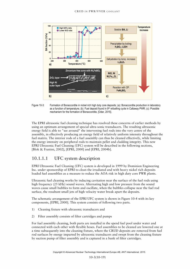
C R U D I N P W R / V V E R C O O L A N T
Copyright © Advanced Nuclear Technology International Europe AB, ANT International, 2015.
10-3(10-19)
Figure 10-3: Formation of Bonaccordite in nickel rich high duty core deposits; (a): Bonaccordite production in laboratory as a function of temperature; (b): Fuel deposit found in 9th refuelling cycle in Callaway PWR; (c): Possible mechanism for the formation of Bonaccordite, [Odar, 2015].
The EPRI ultrasonic fuel cleaning technique has resolved these concerns of earlier methods by using an optimum arrangement of special ultra-sonic transducers. The resulting ultrasonic energy field is able to "see around" the intervening fuel rods into the very centre of the assembly, in effectively producing an energy field of relatively uniform intensity throughout the fuel matrix. The interior rods of a fuel assembly can thus be cleaned effectively, while limiting the energy intensity on peripheral rods to maintain pellet and cladding integrity. This new EPRI Ultrasonic Fuel Cleaning (UFC) system will be described in the following sections, [Blok & Frattini, 2002], [EPRI, 2000] and [EPRI, 2004b].
10.1.1.1 UFC system description
EPRI Ultrasonic Fuel Cleaning (UFC) system is developed in 1999 by Dominion Engineering Inc. under sponsorship of EPRI to clean the irradiated and with heavy nickel rich deposits loaded fuel assemblies as a measure to reduce the AOA risk in high duty core PWR plants.
Ultrasonic fuel cleaning works by inducing cavitation near the surface of the fuel rods using high frequency (25 kHz) sound waves. Alternating high and low pressure from the sound waves cause small bubbles to form and oscillate, when the bubbles collapse near the fuel rod surface, the resultant small jets of high velocity water break apart the deposits.
The schematic arrangement of the EPRI UFC system is shown in Figure 10-4 with its key components, [EPRI, 2000]. This system consists of following two parts.
1) Cleaning fixture with ultrasonic transducers and
2) Filter assembly consists of filter cartridges and pumps
For fuel assembly cleaning, both parts are installed in the spend fuel pool under water and connected with each other with flexible hoses. Fuel assemblies to be cleaned are lowered one at a time subsequently into the cleaning fixture, where the CRUD deposits are removed from fuel rod surfaces by energy imparted by ultrasonic transducers and swept from the cleaning fixture by suction pump of filter assembly and is captured in a bank of filter cartridges.

C R U D I N P W R / V V E R C O O L A N T
Copyright © Advanced Nuclear Technology International Europe AB, ANT International, 2015.
11-1(11-11)
11 Conclusive summary and recommendations The information given in this report is summarized in the following:
11.1 Preventive tools to minimize CRUD inventory and radiation fields during plant design phase
The discussions on preventive tools to minimize CRUD inventory and radiation fields during plant design phase can be summarized as follows:
• The measures to control the coolant CRUD as preventive tool starts actually during the design phase of the PWR plants far before their operation.
• The selection of the steam generator tubing material is one of the most important issue with respect to avoid bad influence on fuel performance and out-of-core radiation field increase caused by nickel release and deposition on fuel assemblies from nickel base alloys. Accordingly the selection of iron base alloys for steam generator tubing with lower nickel content, e.g. Alloy 800, is the better choice with respect to avoid the fuel performance and out-of-core radiation problems caused by excess nickel in the fuel deposits.
• 60Co is produced from 59Co by radiation in the core is the main source for the radiation fields in out-of-core areas the nuclear plant. The sources for 59Co are the cobalt base materials, e.g. stellites, that are used as hard-face (HF) materials in several locations in reactor coolant system such as in reactor pressure vessel internals and valves to reduce the material release by wear and/or corrosion.
• In order to reduce the radiation fields lot of efforts and studies were performed with respect to minimize the cobalt sources in PWR industry. The most important results were achieved by replacement of stellites from the reactor vessel internals performed by Siemens in their PWR plants.
• The progressive improvements performed in Siemens designed PWR plants by stellite replacement with respect to radiation field reduction revealed that the reduction of cobalt base materials out-of-core area, such as in Main Coolant Pumps and/or valves that communicate directly with reactor coolant system does not result in remarkable dose rate reductions as achieved by replacements in reactor pressure vessel.
• In addition to stellite removal program from the core internals, limitation of cobalt impurities in the reactor coolant system structural materials can also contribute remarkable to radiation field control. Based on the field experience, that is the reason why since 1980s limits on cobalt impurity concentrations were specified in reactor coolant system structural materials, especially on steam generator tubing materials due to their huge surface areas (about 70–75% of the total RCS surface area).
• One of the most important events with respect to unexpected radiation field increase that was caused by uncontrolled 60Co impurities in the blazed nickel on Inconel 718 fuel spacer grids during the fuel assembly manufacturing by nickel platting of the grids before blazing. This problem was counterattacked by controlling the cobalt concentration of the nickel bath for electro-nickel platting of Inconel 718 grids or even better by replacing the Inconel 718 spacer grids by zircaloy grids.

C R U D I N P W R / V V E R C O O L A N T
Copyright © Advanced Nuclear Technology International Europe AB, ANT International, 2015.
11-2(11-11)
11.2 Hot functional tests The information about hot functional test measures to control coolant CRUD can be summarized as follows:
• HFT are the tests that are performed during the commissioning of the nuclear power plants to check if the plant systems are operating according to their design criteria. During these HFTs the structural material surfaces of the reactor coolant system are exposed first time to high-temperature water. Accordingly, the adequate chemistry program during the HFT of the plant commissioning is being of crucial importance to its subsequent operational performance and behaviour with respect to coolant CRUD control (reduced fuel deposits and its consequences such as fuel clad corrosion, AOA, out-of-core radiation fields and also steam generator tube degradation). For these reasons, a so-called “Passivation” process is integrated in these HFTs with the aim to produce adequate passive oxide layers on the surfaces of structural materials that protects the materials against corrosion and reduces the metal release rates.
• Almost all plant designer/supplier (Westinghouse, Combustion Engineering, Siemens, etc.) were recommending slightly alkaline and reducing chemistry program for the HFTs. This was applied by injecting lithium hydroxide under oxygen free conditions, which was removed before increasing the coolant temperature to operational conditions (>280°C) either by hydrazine injection or by Deaerators. For alkalization it is recommended to use 6Li depleted lithium-7 hydroxide; because, the natural lithium contains >6% 6Li that is a significant tritium source.
• In 1990s based on published knowledge that hydrogen addition during HFTs has beneficial effect on the improvement of the passive oxide layers resulting in more reduced metal release rates, PWR industry started to consider hydrogen injection for the passivation stage of the HFTs. Sizewell B PWR plant that modified its HFT chemistry program by hydrogen injection claims the HFTs chemistry program with hydrogen injection for their favorable radiation field evolution experienced in their subsequent fuel cycles.
• Siemens performed a further modification of the classical HFT chemistry program beginning of 2000s with zinc addition. Basis for this modification was the field experience gained at zinc PWR plants with significant radiation field reductions. The evaluation of this zinc chemistry experience confirmed that zinc stabilizes the passive oxide layers on the surfaces of structural materials by incorporating in spinel oxide layers, which provides better protection of materials and results in improved CRUD control. The first zinc application during HFT was performed in 2000 at Angra Unit 2 PWR plant in Brazil that was followed later in 2008 by application in Tomari Unit 3 in Japan. In the subsequent fuel cycles, the radiation field data of these both PWR plants that contain stellites in their reactor coolant systems were extremely low, comparable with dose rates experienced at stellite free PWR plants.
11.3 Control of CRUD by operating coolant chemistry
The summary how operating coolant chemistry can influence the CRUD control is explained in the following:
• Adequate coolant CRUD control can be achieved in two ways:
1) By “Source Term Reduction”, i.e. by reducing the corrosion product release from the out-of-core surfaces, especially from the steam generator tubing surfaces that have the highest surface area in RCS by improving the protective oxide layers on these surfaces;

C R U D I N P W R / V V E R C O O L A N T
Copyright © Advanced Nuclear Technology International Europe AB, ANT International, 2015.
11-4(11-11)
• Influence of zinc injection on radiation field reduction by zinc injection by two mechanisms:
1) Based on its highest Site Preference Energy for tetrahedral sites in spinel structure, zinc can replace other cations like, cobalt (58Co and 60Co) but also iron and nickel.
2) Zinc can fill up the vacancies and grain boundary defect locations in the outer oxide layers, and thus seals the oxide surfaces, which prevents the further radio-cobalt up-take from the reactor coolant.
• Based on these properties, zinc injection is accompanied, especially at the beginning, by release of corrosion products, iron and nickel, from the oxide layers on the out-of-core structural material surfaces. Based on this experience, a cautious introduction of zinc injection is mandatory, especially for high duty core PWR plants having nickel base steam generator tubing alloys (Alloy 600MA/TT and Alloy 690TT), which have AOA risk.
• Fuel vendors have criteria to be followed for first cycle (introduction) and subsequent cycle zinc injection applications, which mainly consider limitation of corrosion product and silica concentrations in the coolant; and also time of zinc injection start in the cycle for PWR plants with AOA risk.
• During the introduction of the zinc injection all injected zinc will incorporate into oxide layers, therefore, zinc cannot be monitored in the coolant, till all oxide surfaces are saturated by zinc. This so-called incubation time depends on the amount and morphology of the oxide layer inventory of the RCS and accordingly it is plant specific. Based on field experience incubation time can take from several hours (new plants during hot-functional tests) up to several weeks.
• During power operation, zinc injection should be applied continuously. A break of injection results in release of zinc from the oxide surfaces, which affects the quality of the oxide layers with respect to CRUD control by source term reduction.
• For monitoring of zinc it is recommended to use short and cold sampling line upstream purification mix-bed resin columns in the letdown line of the CVCS; instead of long and high-temperature RCS sampling line. The reason is, the inner surface of the high-temperature sampling is covered with oxide layers, which adsorbs zinc (also corrosion products like Co, Fe and Ni) and biased the sampling results. This was observed and confirmed at field in many PWR plants.
Low hydrogen concentration:
• Lowering of coolant hydrogen concentration decreases the excess nickel content of the fuel deposits, which results in dose reduction on out-of-core surfaces caused by 58Co and can also reduce the shut-down nickel release.
• This coolant chemistry tool for control of fuel nickel content was confirmed at field by Japanese PWR industry at Tsuruga Unit 2 PWR plant. It is mainly important for PWR plants that have nickel base alloys (Alloy 600MA/TT and Alloy 690TT) for their steam generator tubes, which have accordingly excess of nickel in their fuel deposits. For PWRs with iron base Alloy 800 SG tubes and for VVER plants that use stainless steels for their SG tubes, this measure of lowering the coolant hydrogen concentration has less important; because those plants don’t experienced high nickel content in their fuel deposits.
• For low hydrogen strategy it is recommended to operate at the lower limit of the specified hydrogen concentration (about 25 cc/kg or 2 mg/kg). In severe excess nickel deposits lowering of hydrogen concentration can be performed down to 15 cc/kg (1.3 mg/kg). This hydrogen level in the reactor coolant without causing water radiolysis is qualified at field by Japanese PWR industry.
C R U D I N P W R / V V E R C O O L A N T
Copyright © Advanced Nuclear Technology International Europe AB, ANT International, 2015.
12-1(12-10)
12 References Ahlberg E. and Rebensdorff B., In Proc. BNES Conf. water Chemistry Nucl. Reactor Syst. 6,
Bournemouth, UK, 12-15 Oct. 1992, Vol. 2, 278-5/8, 1992.
Aizawa Y., Ouchi K., Hayakawa H., Nakahama S., Nishimura T., Umehara R., Shimizu Y., Kogawa N. and Ojima Z., The Effects of Zinc injection from HFT at TOMARI Unit 3, NPC 2014, International Conference on Water Chemistry of Nuclear Reactor Systems, Sapporo, 2014.
Andresen P. L., Reid R. and Wilson J., SCC mitigation of Ni alloys and weld metals by optimizing dissolved hydrogen, 14th Int. Conf. on Environmental Degradation of Materials in Nuclear Power Systems, Virginia Beach, VA, US, August 23-27, 2009.
Ayres J. A., Decontamination of Nuclear Reactors and Equipment, The Ronald Press Company, New York, 1970.
Barton M. et al., Corrosion product measurements at the Sizewell- B PWR, International Conference on Water Chemistry in Nuclear Reactor systems, Bournemouth, 2000.
Bates C., Garbett K., Hinds K., Lancaster G., Mantell M. and Renn G., Development of Corrosion Product Behaviour and Radiation Fields at the Sizewell B PWR from 1995 to 2008, Proceedings of the International Conference on Water Chemistry in NPP, Berlin, Germany, Oct. 2008.
Baum A., Restricted geometries and deposits, Chapter 6 of the ASME Handbook on Water Technology for Thermal Power Systems. Paul Cohen, Editor-in-Chief, New York: The American Socity of Mechanical Engineers, pp. 279-338, 1989.
Beaman T. A. and Smee J. L., Experience With Dilute Chemical Decontamination, Presented at Decontamination of Nuclear Facilities, International Joint Topical Meeting ANS-CAN, Sheraton Brock Hotel, Niagara Falls, Canada, Sept. 19-22, 1982.
Bell K. E., Heiny R. and Tippetts D., Chemical decontamination of nuclear power plant reactor systems, 6th International Seminar on Primary and Secondary Side Water Chemistry of NPP’s, Budapest, Hungary, May 16-19, 2005.
Bénézeth P., Palmer D. A., Wesolowski D. J. and Xiao C., New measurements of the solubility of zinc oxide from 150 to 350°C, Journal of Solution Chemistry 31, p. 947-973, 2002.
Bengtsson B., Experience concerning corrosion product sampling of reactor coolant, EPRI, RFP-Meeting, Working Group 1 Tampa Florida, Feb. 27-28, 2002.
Bengtsson B., Aronsson P-O., Larsson S. and Andersson P-O., Experience with elevated pH and Lithium in Ringhals PWRs, International Conference on Water Chemistry in Nuclear Reactor System, NPC’08, Paper L1-4s, Berlin, Germany, 2008.
Bengtsson B., Elevated pH and lithium: Possible tool to reduce radiation source terms, WANO Workshop on Reduction of Dose Rate in PWRs, Würzburg, 2009.
Bengtsson B., Svanberg P., Dingee J., Pellman A. and Wells D., Experience with High Efficiency Ultrasonic Fuel Cleaning using a side-stream sampling system at Ringhals Unit 4, International Conference on Water Chemistry of Nuclear Reactor Systems, NPC 2014, Atomic Energy Society of Japan, Sapporo, 26-31 October 2014.
Bergmann C. A., Durkosh D. E., Lindsay W. T. and Roesmer J., The role of coolant chemistry in PWR radiation-field build-up, EPRI Report NP-4247, 1985.

C R U D I N P W R / V V E R C O O L A N T
Copyright © Advanced Nuclear Technology International Europe AB, ANT International, 2015.
12-2(12-10)
Berger M., Brun C. and Clinard M-H., PWR to EPR: Evolutionary Chemistry for the new French Nuclear Power Plants; Design and Operation at Flamanville-3, International Conference on Water Chemistry of Nuclear Reactor Systems P1.14, J, Jeju Island, Korea, October 23–26, 2006.
Berry W. E. and Diegle R. B., Survey of Corrosion Product Generation, Transport and Deposition in Light Water Nuclear Reactors, EPRI Final Report, NP-522, March 1979.
Bertholdt H. O. and Papesch R., EPRI –Chemical Decontamination Conference, The state of the art decon process for every job, Siemens presentations in Embassy Suites, Greenville, South Carolina, May 1998.
Blok J. and Frattini P., Advances in Ultrasonic Fuel Cleaning, International Conference on Water Chemistry in Nuclear Reactor System, BNES 8, 2002.
Bojinov M., Buddas T., Halin M., Helin M., Kinnunen P., Kvarnström R., Laitinen T., Mutilainen E., Mäkelä K., Reinvall A., Saario T., Sirkiä P. and Tompuri K., Water Chemistry in Nuclear Reactor Systems. Operation Optimisation and New Developments, In Proceedings of Chimie 2002, International Conference, Avignon, France, SFEN, French Nuclear Energy Society, paper No.143 (CD-ROM publication), 2002.
Bolz M., Hoffmann W. and Ruehle W., Characterization of colloids in primary coolant, International Conference on Water Chemistry of Nuclear Reactor systems 7, BNES, 1996.
Bolz M., Personnel communication; courtesy of EnBW, 2011.
Bradbury D., Segal M. G., Sellers R. M., Swan T. and Wood C. J., Development of LOMI Chemical Decontamination Technology, EPRI Report NP-3177, July 1983.
Bradbury D., Preliminary unpublished data from Bradtec Decon Technologies, Work in progress, May 1999.
Bretelle J-L., Guinard L., Andrieu C. and Daquait F., EdF strategy for the PWR primary coolant pH, International Conference on Water Chemistry of Nuclear Reactor Systems, San Francisco, 2004.
Brobst G., PWR Shutdown Chemistry Practices, 1998 through 2001, EPRI TR-1007307, Palo Alto, CA, 2002.
Byers W. A., Wang G. and Deshon J. C., The limits of zinc addition in high duty PWRs, International Conference on Water Chemistry in Nuclear Reactor Systems, Berlin 2008.
Carrette F., Cattant F., Legras L., Bardet F., Merrer M. and Guinard L., Impact of the surface state of steam generator tubes on the release of corrosion products in pressurized water reactors, International Conference on Water Chemistry of Nuclear Reactor Systems, Jeju Island, Korea, October 23-26, 2006.
Cattant F., PWR type plants. Reactor coolant system shutdown and start up chemistry. Analysis of some foreign Utilities practices, EDF report HT-44/01/050/A. 2002.
Chen J., Bengtsson B., Bergqvist H. and Jädernäs D., On the phase compositions of fuel CRUD formed in PWRs using steam generator tubing materials of alloy 600 and 690, Proceedings of International Conference on Water Chemistry in Nuclear Reactor systems, Paris, France, 2012.
Chu Fang C., The Ongoing Efforts on Water Chemistry Optimization of BWRs/PWRs in Taiwan, Proceedings Symposium on Water Chemistry and Corrosion of Nuclear Power Plants in Asia, Paper 4, Taipei, Taiwan, September 26-28, 2007.