crushing behavior and energy … international conference on composite materials xi’an, 20-25th...
TRANSCRIPT
21st International Conference on Composite Materials Xi’an, 20-25th August 2017
CRUSHING BEHAVIOR AND ENERGY ABSORPTION OF PVC FOAM: AN ANISOTROPIC VISCO-ELASTIC-PLASTIC-DAMAGE MODEL
Michelle S. Hoo Fatt1, Anish J. Jacob2, Xiaolong Tong3 and Arturo MacHado-Reyes4
1,2,3,4 Department of Mechanical Engineering The University of Akron Akron, OH 44532-3903
Keywords: PVC foam, hysteresis, visco-elastic-plastic-damage response.
ABSTRACT
Structural polymeric foams are used as the core material in lightweight composite sandwich ship structures. There is a need to develop more accurate material models that can be used to predict the crushing behavior, energy absorption and residual properties of polymeric foams. Many of the crushable foam models are based on metal plasticity and do not distinguish the anisotropic, visco-elastic-plastic material characteristics of a polymeric foam. The objective of this research is to develop more accurate foam constitutive models that can be used to predict crushing behavior, energy absorption and damping properties of structural polymeric foams. Experiments were done to determine the multi-axial, elastic-plastic and hysteresis behavior of Divinycell PVC H100 foam. The foam, which was transversely isotropic, exhibited elastic-plastic response followed by viscoelastic hysteresis in compression, shear and combined compression and shear. It was found that once the parent material of the foam yielded, foam cell geometries were permanently altered and the foam responded with reduced modulus and high viscoelastic damping. A Tsai-Wu plasticity model, including combined kinematic and isotropic hardening, was developed to accurately describe multi-axial yielding of the foam. Good agreement was found between the proposed visco-elastic-plastic-damage constitutive model and experimental results. 1 INTRODUCTION
Structural polymeric foams are used as the core material in lightweight composite sandwich ship structures. Traditional sandwich theory suggests that the primary function of the foam core is to transmit shear to the fachesheets, thereby rendering high bending stiffness and strength from a panel with minimum weight penalty. Recent analysis on the underwater blast response of PVC foam-core composite sandwich panel, however, shows that in addition to the above, PVC foams have blast mitigation effects via energy absorption during plastic core crushing. It was found that sandwich panels with softer more ductile foam cores offer better blast resistance than panels with stiffer and stronger foams because of the associated energy dissipation due to core crushing [1]. This is especially true in water blast cases where yielding of the foam is multiaxial, specifically under transverse shear, transverse compression and sometimes in-plane compression.
A foam-core sandwich panel is able to resist blast loading even after the foam has plastically deformed, as long as fracture has not ensued. Plastic deformation of the foam parent material, which is semi-rigid PVC for Divinycell PVC H100 foam, will cause permanent changes in the geometry of the foam cells and hence, a corresponding change in the overall material behavior of the foam. Such behavior after permanent, plastic deformation has not been addressed until very recently [2-5]. Chen and Hoo Fatt [2] characterized the out-of-plane (transverse) and in-plane, elastic-plastic hysteresis behavior of PVC H100 foam in compression and shear. This foam exhibited transversely isotropic properties, with a ratio of out-of-plane to in-plane stiffness and yield strength for the PVC H100 foam to be approximately 3/2 in both the compression and shear modes. Once yielding occurred, the foam underwent permanent damage and exhibited hysteresis, mainly in the form of viscoelasticity. Similar behavior was reported for the form under combined transverse compression and shear in Refs. [4-5]. This research expands on previous work by incorporating tri-axial material stress-strain behavior of

Michelle S. Hoo Fatt, Anish J. Jacob, Xiaolong Tong and Arturo MacHado-Reyes
the foam. There is a need to develop more accurate material models that can be used to predict the crushing
behavior, energy absorption and residual strength properties of polymeric foams. Many of the crushable foam models are based on metal plasticity [6] and do not distinguish the anisotropic, visco-elastic-plastic material characteristics of a polymeric foam. In this paper, we describe an experimental program to determine the tri-axial hysteresis behavior of Divinycell PVC H100 foam. Results from these experiments are used to develop a three-dimensional constitutive model that can be used to predict the crushing behavior and energy absorption of the foam. The proposed study would help quantify the blast mitigation capability of polymer foams (energy absorption, residual strength, damping properties).
2 FOAM HYSTERESIS EXPERIMENTS
A pressure vessel apparatus, as depicted in Fig. 1(a), was made to be used in conjunction with an MTS servo-hydraulic machine to determine tri-axial material properties, including plastic deformation, damage and hysteresis of PVC H100 foam. Inside the pressure vessel, uniaxial tension/compression, shear and bi-axial Arcan/butterfly specimens, as shown in Fig. 1(b), are exposed to pressurized air. The 0 deg Arcan butterfly specimen is used for shear, while the 15, 30, 45, 60 and 75 deg Arcan butterfly specimens are used for combined normal and shear modes. Digital Image Correlation (DIC) is used to determine specimen strains, while the load cell of the MTS machine and pressure gages are used to determine specimen stresses.
(a) (b)
Figure 1 Pressure vessel experiment to obtain tri-axial hysteresis of PVC foam: (a) cut-away view inside pressure chamber and (b) assorted Arcan/butterfly specimen and tension/compression fixtures.
Each specimen is subjected to cyclic under displacement control at a constant displacement rate of 1.27 mm/s. Hysteresis loops are acquired after plastic deformation has occurred at pre-determined maximum displacement amplitudes. This is done for each mode of loading and for several maximum displacement amplitudes. The following sections summarize experimental data that has been acquired in compression (both out-of-plane and in-plane), out-of-plane or transverse shear and combined
15 o0o
75o
30 o60o
45o

21st International Conference on Composite Materials Xi’an, 20-25th August 2017
transverse compression and shear modes. Tri-axial material tests are currently underway, and will be presented at a later time. 2.1 Compression
Compression tests were done on 2.54cm x 2.54cm x 2.54cm cubes, which were sandwiched between platens (blocks rigidly connected to the piston rod of the cylinder.) In previous work [2-3], compression specimens were glued to the platens, but in these experiments the foam is not constrained or glued to the platens and instead allowed to expand freely in the transverse direction. The loading-unloading cycles after reaching maximum displacement are only acquired when the specimen is in contact with the platens. Figures 2(a) and (b) show compressive stress-strain curves for the foam in the out-of-plane and in-plane directions, respectively. Stress and strain are defined as nominal values using dimensions of the entire specimen. For example, strain is equal to the relative displacement between platens divided by the distance between the platens. Tests were done at six maximum displacement amplitudes, and each result shown in Figs. 2(a) and (b) is from a separate specimen.
(a) (b) Figure 2 Compression hysteresis: (a) out-of-plane compressive stress-strain curve and (b) in-plane compressive stress-strain curve.
After initial yield, cells buckle and undergo permanent deformation. The hysteresis loops during unloading reveal viscoelasticity and a reduced modulus. In fact, the foam modulus decreases with increasing maximum displacement amplitude or permanent plastic strains. Such a modulus degradation signifies damage. Hence, we call the unloading behavior a viscoelastic damage process.
2.2 Shear
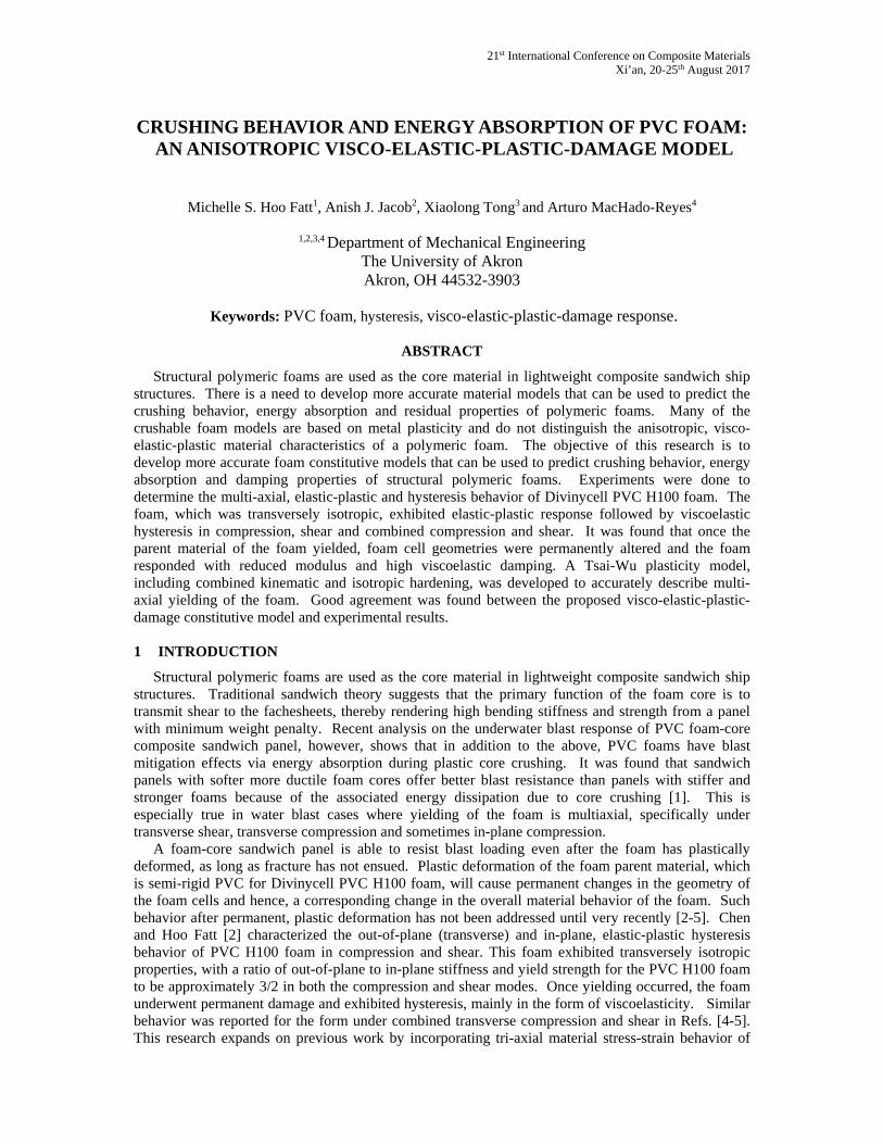
The 0 deg Arcan butterfly specimen, depicted in Fig. 1 (b), is used to obtain transverse shear stress-strain curves. This specimen has an overall dimension of 35mm x 25.54mm x 15mm thick. A fillet radius is 5mm is used to create the neck region. Digital Image Correlation (DIC) with the ncorr software [7] is used to obtain the shear strain in the center of the butterfly specimen. A typical shear strain distribution in the specimen from this software is shown in Fig. 3(a). One can see that the shear is localized and almost uniformly distributed in center of the butterfly specimen. Very highly localized strains also develop near the center region where the fillet radius in the foam specimen ends. Hysteresis stress-strain curves for 0 deg Arcan specimens at various maximum displacements and a constant displacement rate of 1.27 mm/s are shown in Fig. 3(b). As in the case of compression, one can identify viscoelastic damage in the hysteresis loops during unloading.
Michelle S. Hoo Fatt, Anish J. Jacob, Xiaolong Tong and Arturo MacHado-Reyes
(a) (b) Figure 3 Transverse shear hysteresis: (a) shear strain distribution from DIC and (b) shear stress-strain curve.
2.3 Combined Compression and Shear
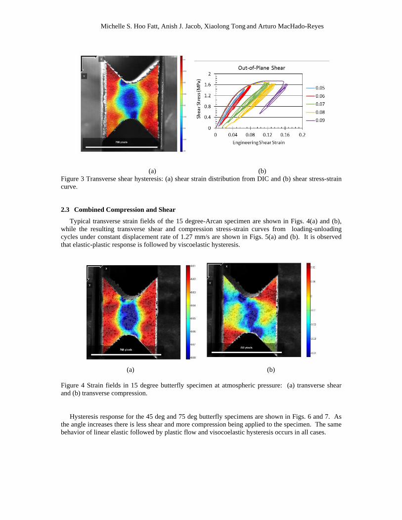
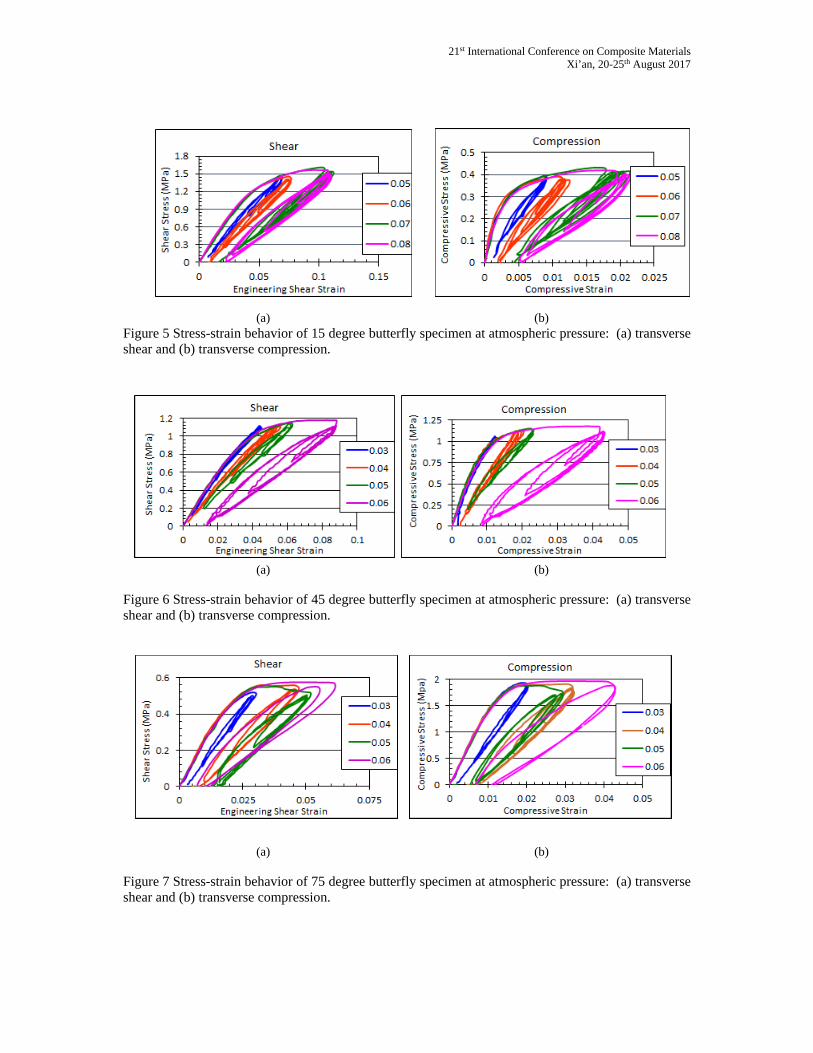
Typical transverse strain fields of the 15 degree-Arcan specimen are shown in Figs. 4(a) and (b), while the resulting transverse shear and compression stress-strain curves from loading-unloading cycles under constant displacement rate of 1.27 mm/s are shown in Figs. 5(a) and (b). It is observed that elastic-plastic response is followed by viscoelastic hysteresis.
(a) (b)
Figure 4 Strain fields in 15 degree butterfly specimen at atmospheric pressure: (a) transverse shear and (b) transverse compression.
Hysteresis response for the 45 deg and 75 deg butterfly specimens are shown in Figs. 6 and 7. As
the angle increases there is less shear and more compression being applied to the specimen. The same behavior of linear elastic followed by plastic flow and visocoelastic hysteresis occurs in all cases.
21st International Conference on Composite Materials Xi’an, 20-25th August 2017
(a) (b)
Figure 5 Stress-strain behavior of 15 degree butterfly specimen at atmospheric pressure: (a) transverse shear and (b) transverse compression.
(a) (b) Figure 6 Stress-strain behavior of 45 degree butterfly specimen at atmospheric pressure: (a) transverse shear and (b) transverse compression.
(a) (b)
Figure 7 Stress-strain behavior of 75 degree butterfly specimen at atmospheric pressure: (a) transverse shear and (b) transverse compression.
Michelle S. Hoo Fatt, Anish J. Jacob, Xiaolong Tong and Arturo MacHado-Reyes
3 VISCO-ELASTIC-PLASTIC DAMAGE MODEL
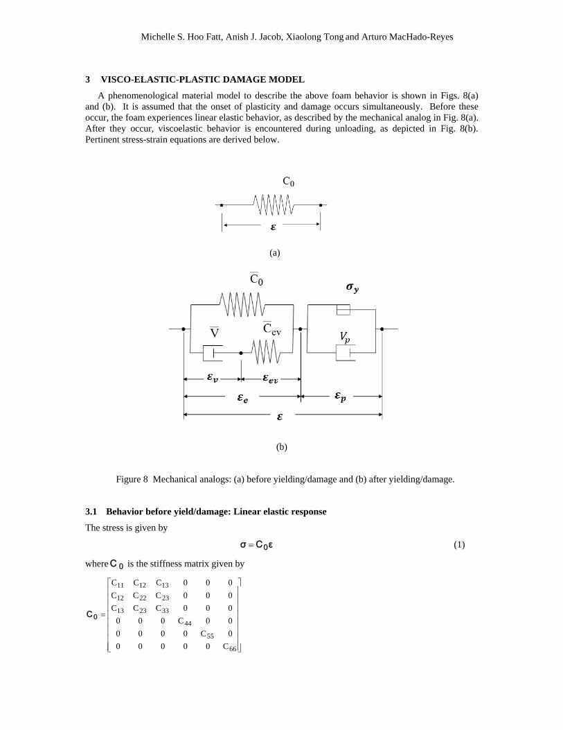
A phenomenological material model to describe the above foam behavior is shown in Figs. 8(a) and (b). It is assumed that the onset of plasticity and damage occurs simultaneously. Before these occur, the foam experiences linear elastic behavior, as described by the mechanical analog in Fig. 8(a). After they occur, viscoelastic behavior is encountered during unloading, as depicted in Fig. 8(b). Pertinent stress-strain equations are derived below.
(a)
(b)
Figure 8 Mechanical analogs: (a) before yielding/damage and (b) after yielding/damage.
3.1 Behavior before yield/damage: Linear elastic response
The stress is given by
εCσ 0 (1)
where 0C is the stiffness matrix given by
66
55
44
332313
232212
131211
C00000
0C0000
00C000
000CCC
000CCC
000CCC
0C
21st International Conference on Composite Materials Xi’an, 20-25th August 2017
and
21133
22322
11EEE
C)(
22113323132212
12EEEE
C)(
33221113231213
EEEC
)(
22233
21311
22EEE
C)(
3322221312112323
EEEEC
)(
33222221211
33EEEE
C)(
2344 GC 1355 GC 1266 GC
and 332223131233112233322
213
222
2122211 EE2EEEEEEE .
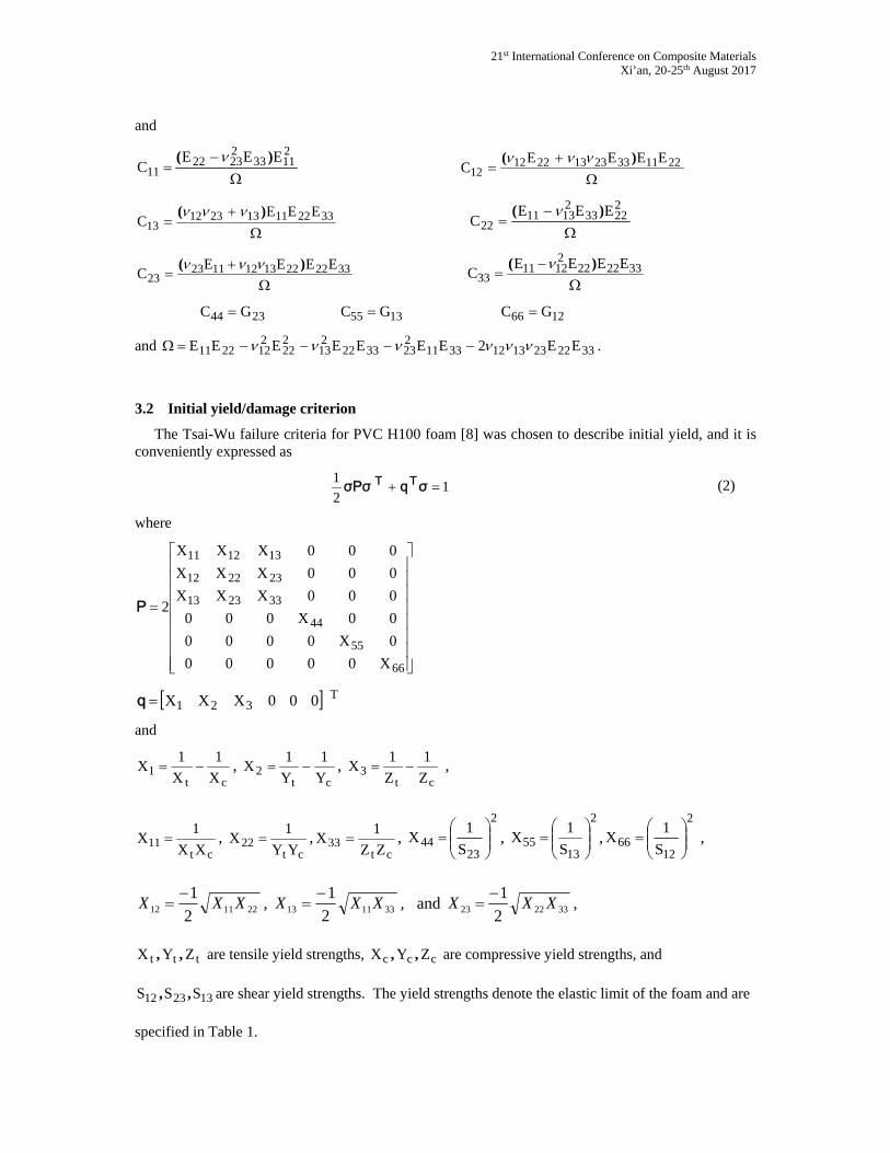
3.2 Initial yield/damage criterion
The Tsai-Wu failure criteria for PVC H100 foam [8] was chosen to describe initial yield, and it is conveniently expressed as
12
1 σqσPσ TT (2)
where
66
55
44
332313
232212
131211
X00000
0X0000
00X000
000XXX
000XXX
000XXX
2P
T321 000XXXq
and
ct1 X
1
X
1X ,
ct2 Y
1
Y
1X ,
ct3 Z
1
Z
1X ,
ct11 XX
1X ,
ct22 YY
1X ,
ct33 ZZ
1X ,
2
2344 S
1X
,
2
1355 S
1X
,
2
1266 S
1X
,
221112 2
1XXX
, 331113 2
1XXX
, and 332223 2
1XXX
,
ttt ZYX ,, are tensile yield strengths, ccc ZYX ,, are compressive yield strengths, and
132312 SSS ,, are shear yield strengths. The yield strengths denote the elastic limit of the foam and are
specified in Table 1.
Michelle S. Hoo Fatt, Anish J. Jacob, Xiaolong Tong and Arturo MacHado-Reyes
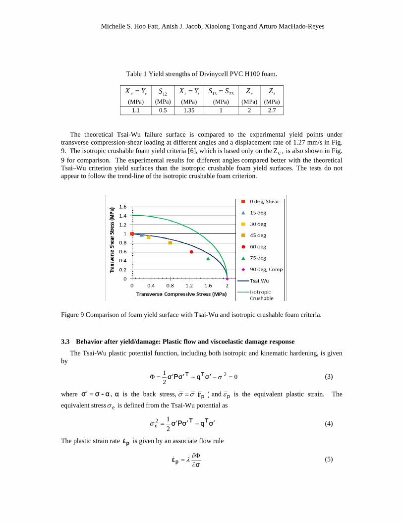
Table 1 Yield strengths of Divinycell PVC H100 foam.
cc YX
(MPa) 12S
(MPa) tt YX
(MPa)
2313 SS
(MPa)
cZ
(MPa)
tZ
(MPa) 1.1 0.5 1.35 1 2 2.7
The theoretical Tsai-Wu failure surface is compared to the experimental yield points under transverse compression-shear loading at different angles and a displacement rate of 1.27 mm/s in Fig. 9. The isotropic crushable foam yield criteria [6], which is based only on the cZ , is also shown in Fig.
9 for comparison. The experimental results for different angles compared better with the theoretical Tsai–Wu criterion yield surfaces than the isotropic crushable foam yield surfaces. The tests do not appear to follow the trend-line of the isotropic crushable foam criterion.
Figure 9 Comparison of foam yield surface with Tsai-Wu and isotropic crushable foam criteria.
3.3 Behavior after yield/damage: Plastic flow and viscoelastic damage response
The Tsai-Wu plastic potential function, including both isotropic and kinematic hardening, is given by
02
1 2 σqσPσ TT (3)
where ,α-σσ α is the back stress, ︶︵p and p is the equivalent plastic strain. The
equivalent stress e is defined from the Tsai-Wu potential as
σqσPσ TT 2
12e (4)
The plastic strain rate pε is given by an associate flow rule
σεp
(5)
21st International Conference on Composite Materials Xi’an, 20-25th August 2017
where is the plastic multiplier. In terms of the P and q , Eq. (5) reduces to
σqσPσ
σqPσσεTT
TTp
2
1 (6)
The back stress is given in terms of a kinematic hardening law
pεHα (7)
where H is the kinematic hardening coefficient matrix.
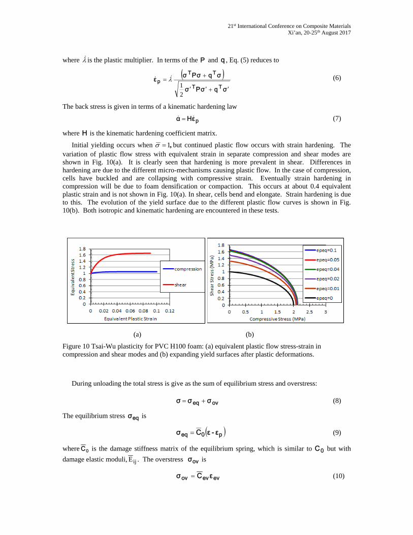
Initial yielding occurs when ,1 but continued plastic flow occurs with strain hardening. The variation of plastic flow stress with equivalent strain in separate compression and shear modes are shown in Fig. 10(a). It is clearly seen that hardening is more prevalent in shear. Differences in hardening are due to the different micro-mechanisms causing plastic flow. In the case of compression, cells have buckled and are collapsing with compressive strain. Eventually strain hardening in compression will be due to foam densification or compaction. This occurs at about 0.4 equivalent plastic strain and is not shown in Fig. 10(a). In shear, cells bend and elongate. Strain hardening is due to this. The evolution of the yield surface due to the different plastic flow curves is shown in Fig. 10(b). Both isotropic and kinematic hardening are encountered in these tests.
(a) (b)
Figure 10 Tsai-Wu plasticity for PVC H100 foam: (a) equivalent plastic flow stress-strain in compression and shear modes and (b) expanding yield surfaces after plastic deformations.
During unloading the total stress is give as the sum of equilibrium stress and overstress:
oveq σσσ (8)
The equilibrium stress eqσ is
p0eq ε-εCσ (9)
where 0C is the damage stiffness matrix of the equilibrium spring, which is similar to 0C but with
damage elastic moduli, ijE . The overstress ovσ is
evevov εCσ (10)
Michelle S. Hoo Fatt, Anish J. Jacob, Xiaolong Tong and Arturo MacHado-Reyes
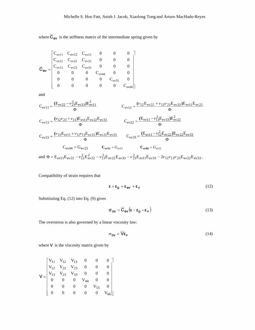
where evC is the stiffness matrix of the intermediate spring given by
ev66
ev55
ev44
ev33ev23ev13
ev23ev22ev12
ev13ev11
C00000
0C0000
00C000
000CCC
000CCC
000CCC ev12
evC
and
2
11ev33ev22322ev
ev11EEE
C)(
22ev11ev33ev231322ev12
ev12EEEE
C)(
33ev22ev11ev132312ev13
EEEC
)(
2
22ev33ev21311ev
ev22EEE
C)(
33ev22ev22ev131211ev23ev23
EEEEC
)(
33ev22ev22ev21211ev
ev33EEEE
C)(
23evev44 GC 13evGev55C 12evGev66C
and 33ev22ev23131233ev11ev22333ev22ev
213
222ev
21222ev11ev EE2EEEEEEE .
Compatibility of strain requires that
vevp εεεε (12)
Substituting Eq. (12) into Eq. (9) gives
vpevov ε-εεCσ (13)
The overstress is also governed by a linear viscosity law:
vov εV (14)
whereV is the viscosity matrix given by
66
55
44
332313
232212
131211
V00000
0V0000
00V000
000VVV
000VVV
000VVV
V
21st International Conference on Composite Materials Xi’an, 20-25th August 2017
and
21133
22322
11V )(
22113323132212
12V )(
33221113231213V
)(
22233
21311
22V )(
3322221312112323V
)(
33222221211
33)(
V
2344V 1355V 1266V
and 332223131233112233322
213
222
2122211 2 .
Combining Eqs. (13) and (14) gives an evolution equation for vε :
vpevv εεεCεV (15)
The total stress is represented as
vpev0 εεεCεCσ (16)
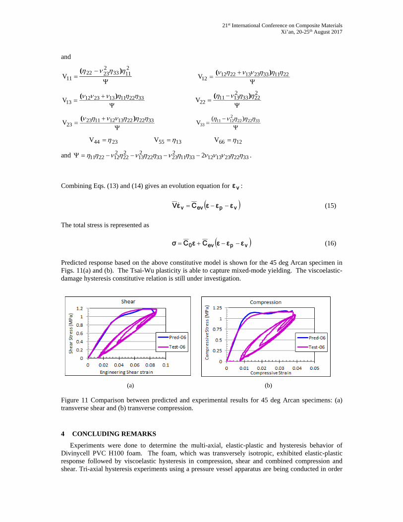
Predicted response based on the above constitutive model is shown for the 45 deg Arcan specimen in Figs. 11(a) and (b). The Tsai-Wu plasticity is able to capture mixed-mode yielding. The viscoelastic-damage hysteresis constitutive relation is still under investigation.
(a) (b)
Figure 11 Comparison between predicted and experimental results for 45 deg Arcan specimens: (a) transverse shear and (b) transverse compression.
4 CONCLUDING REMARKS
Experiments were done to determine the multi-axial, elastic-plastic and hysteresis behavior of Divinycell PVC H100 foam. The foam, which was transversely isotropic, exhibited elastic-plastic response followed by viscoelastic hysteresis in compression, shear and combined compression and shear. Tri-axial hysteresis experiments using a pressure vessel apparatus are being conducted in order
Michelle S. Hoo Fatt, Anish J. Jacob, Xiaolong Tong and Arturo MacHado-Reyes
to expand the material data base beyond biaxial properties, and these will be presented at a later time. A Tsai-Wu plasticity model, including combined kinematic and isotropic hardening, was developed to accurately describe multi-axial yielding of the foam. Good agreement was found between the proposed visco-elastic-plastic-damage constitutive model and experimental results.
ACKNOWLEDGEMENTS
This research was supported under ONR Grant N00014-16-1-2840. The authors thank Dr. Yapa D. S. Rajapakse, Solid Mechanics Program Manager at the Office of Naval Research, for making this work possible, and DIAB for supplying PVC H100 foam panels. We also thank Dale Ertely and Bill Wenzel, Engineering Machine Shop at The University of Akron, for their work and expertise in machining the pressure vessel and specialty fixtures for the experiments.
REFERENCES
[1] M.S. Hoo Fatt and D. Sirivolu, Marine composite sandwich plates under air and water blasts, Marine Structures, 2017 (in press).
[2] L. Chen L and M. S. Hoo Fatt MS, Transversely isotropic mechanical properties of PVC foam under cyclic loading, J Mat Sci 48, 2013, 6786-6796.
[3] M.S. Hoo Fatt and L. Chen, A viscoelastic damage model for hysteresis in PVC H100 foam under cyclic loading, J Cell Plast, 51, 2015, pp. 269–287.
[4] M.S. Hoo Fatt, M. Alkhtany, and D. Sirivolu, Underwater blast resistance and energy absorption of PVC foams in sandwich panel constructions, Proceedings of the 11th International Conference on Sandwich Structures, Ft. Lauderdale, FL, March 20-22, 2016.
[5] M.S. Hoo Fatt, M. Alkhtany, and D. Sirivolu,, Blast mitigation effects of foam-core, composite sandwich structures. in Y.D.S. Rajapakse and S. Gopalakrishnan (Ed.), Blast Mitigation Strategies for Marine Composite and Sandwich Structures, Springer Science & Business Media Singapore Pte Ltd, Singapore, 2017 (in press).
[6] V.S. Deshpande and N. A. Fleck, Multi-axial yield behavior of polymer foams, Acta Mater 49, 2001, 1859–186.
[7] J. Blaber, B. Adair, and A. Antoniou, Ncorr: Open-Source 2D Digital Image Correlation Matlab Software, Experimental Mechanics, 2015.
[8] E.E. Gdoutos, I.M. Daniels and K.-A. Wang, Failure of cellular foams under multiaxial loading, Composite: Part A: Appl Sci Manuf 33, 2002, 163–176.