crystal oscillator - vectron international inc
TRANSCRIPT
Vectron International • 267 Lowell Road, Unit 102, Hudson, NH 03051 • Tel: 1-88-VECTRON-1 • http://www.vectron.com
• Military Systems• Avionics and Instrumentation• Test Equipment• Medical Equipment
Features Applications
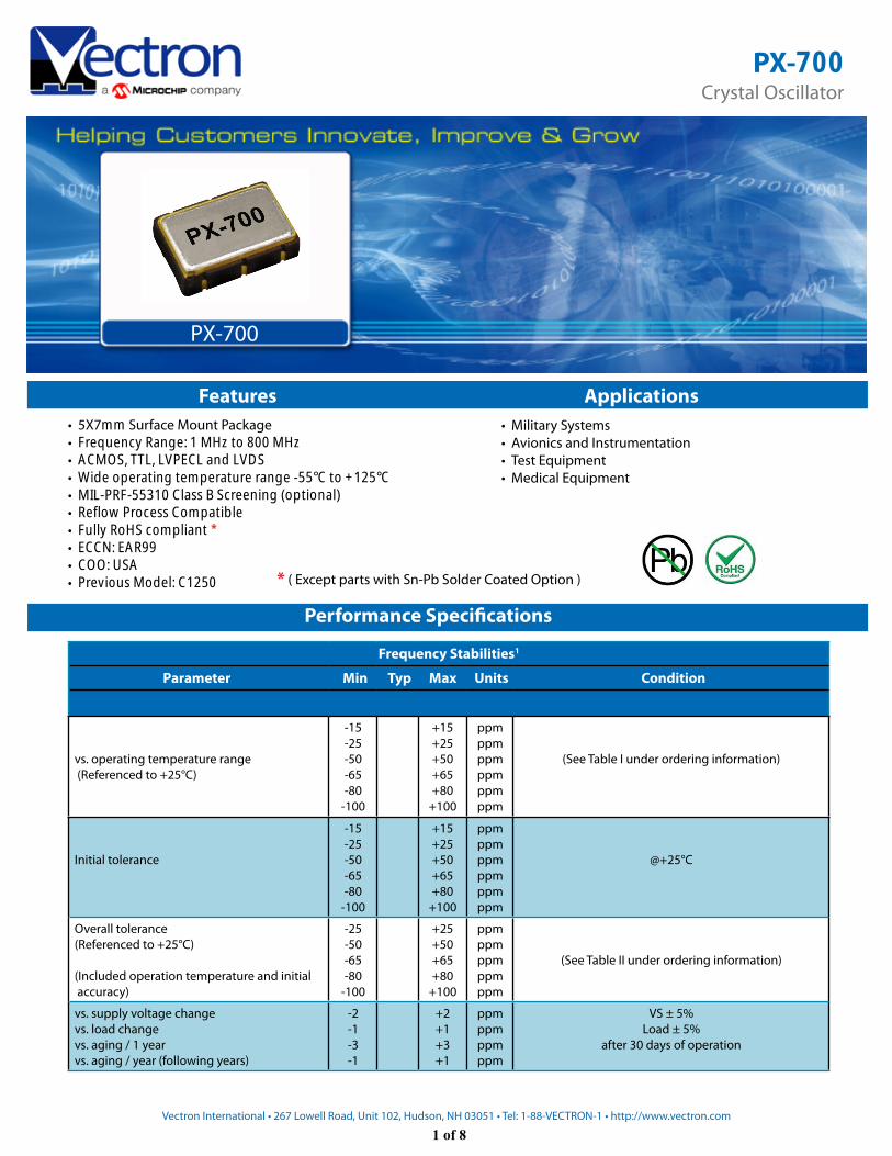
PX-700
* ( Except parts with Sn-Pb Solder Coated Option )
Frequency Stabilities1
Parameter Min Typ Max Units Condition
vs. operating temperature range (Referenced to +25°C)
-15-25-50-65-80
-100
+15+25+50+65+80
+100
ppmppmppmppmppmppm
(See Table I under ordering information)
Initial tolerance
-15-25-50-65-80
-100
+15+25+50+65+80
+100
ppmppmppmppmppmppm
-25-50-65-80
-100
+25+50+65+80
+100
ppmppmppmppmppm
(See Table II under ordering information)
vs. supply voltage changevs. load changevs. aging / 1 yearvs. aging / year (following years)
-2-1-3-1
+2+1+3+1
ppmppmppmppm
VS ± 5% Load ± 5%
after 30 days of operation
Performance Specifications
@+25°C
Overall tolerance(Referenced to +25°C)
• Frequency Range: 1 MHz to 800 MHz• ACMOS, TTL, LVPECL and LVDS• Wide operating temperature range -55°C to +125°C• MIL-PRF-55310 Class B Screening (optional)• Reflow Process Compatible• Fully RoHS compliant *• ECCN: EAR99• COO: USA• Previous Model: C1250
Crystal OscillatorPX-700
(Included operation temperature and initial accuracy)
• 5X7mm Surface Mount Package
1 of 8
Vectron International • 267 Lowell Road, Unit 102, Hudson, NH 03051 • Tel: 1-88-VECTRON-1 • http://www.vectron.com
Parameter Min Typ Max Units Condition
Signal LVDS
Load 60 100 140 ohm Between outputs
Signal Level (Vol) 1.2 VDC
Signal Level (Voh) 1.4 VDC
Differential Voltage (Vod) 240 330 460 mVpeak
Common Mode (Offset) Voltage (Vos) 1.125 1.2 1.375 V
Start-up Time 10 ms
Rise \ Fall Time 600 1000 ps measured @ 20% to 80% of Vod
Duty cycle 45 55 % @ 50% of Vod
Jitter (rms) 51
psps
BW = 10Hz to 20 MHzBW = 12KHz to 20 MHz
Period Jitter (pk-pk) 40 ps 10,000 Samples - Rising edge
Absolute Maximum Ratings
Supply voltage (Vs) 7.0 V with Vs=5.0VDC and 3.3 VDC
Operable temperature range -55 +125 °C
Storage temperature range -62 +125 °C
Additional Parameters
ScreeningVectron Verification
Class B, MIL-PRF-55310, Rev.E
Output Enable
Logic “0“ input = Outputs disabled (Tri-state)Logic “1“ or fl oating input = Outputs enabled) Standard (ACMOS, TTL and LVDS)
Logic “0“ or fl oating input = Outputs enabledLogic “1“ input = Outputs disabled (Tri-state) Standard (LVPECL)
Weight < 2 grams
Processing & Packing Handling & processing note
Standard EnvironmentalsVibration MIL-STD-202, Method 204, Condition G (30 G, 10Hz-2000Hz)
Shock MIL-STD-202, Method 213, Condition I (100 G, 6ms, Sawtooth)
Acceleration MIL-STD-883, Method 2001, Condition A (5000 G, Y1 Plane)
Temperature Cycling MIL-STD-883, Method 1010, Condition B
Solderability MIL-STD-202, Method 208
Leak Test (Fine and Gross) MIL-STD-883, Method 1014, Condition A1 and C1
3 of 8
Thermal Shock MIL-STD-202, Method 107, Condition B
Vectron International • 267 Lowell Road, Unit 102, Hudson, NH 03051 • Tel: 1-88-VECTRON-1 • http://www.vectron.com
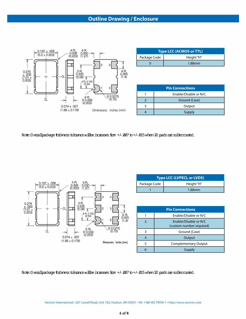
Type LCC (ACMOS or TTL)Package Code Height “H”
0 1.88mm
Pin Connections1 Enable/Disable or N/C
2 Ground (Case)
3 Output
4 Supply
Outline Drawing / Enclosure
Pin Connections1 Enable/Disable or N/C
2 Enable/Disable or N/C(custom number required)
3 Ground (Case)
4 Output
5 Complementary Output
6 Supply
Type LCC (LVPECL or LVDS)Package Code Height “H”
1 1.88mm
4 of 8
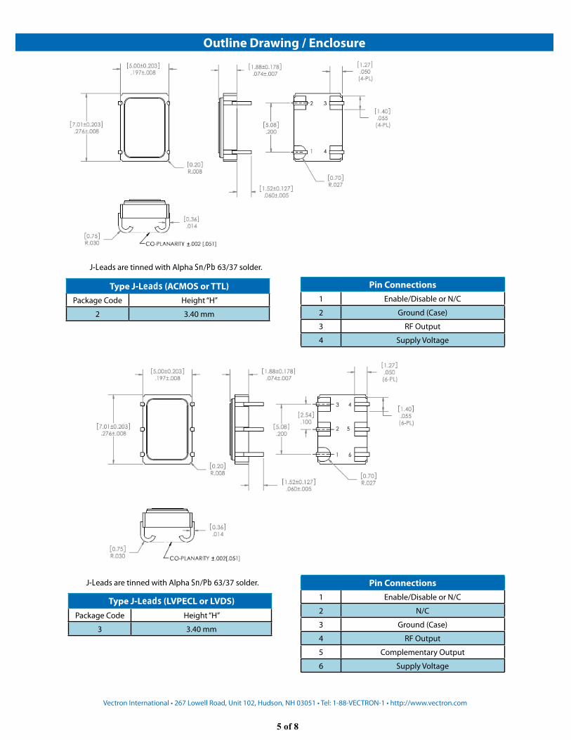
Pin Connections1 Enable/Disable or N/C
2 Ground (Case)
3 RF Output
4 Supply Voltage
Outline Drawing / Enclosure
Pin Connections1 Enable/Disable or N/C
2 N/C
3 Ground (Case)
4 RF Output
5 Complementary Output
6 Supply Voltage
Vectron International • 267 Lowell Road, Unit 102, Hudson, NH 03051 • Tel: 1-88-VECTRON-1 • http://www.vectron.com
Package Code Height “H”
2 3.40 mm
Package Code Height “H”
3 3.40 mm
J-Leads are tinned with Alpha Sn/Pb 63/37 solder.
J-Leads are tinned with Alpha Sn/Pb 63/37 solder.
Type J-Leads (ACMOS or TTL)
Type J-Leads (LVPECL or LVDS)
5 of 8
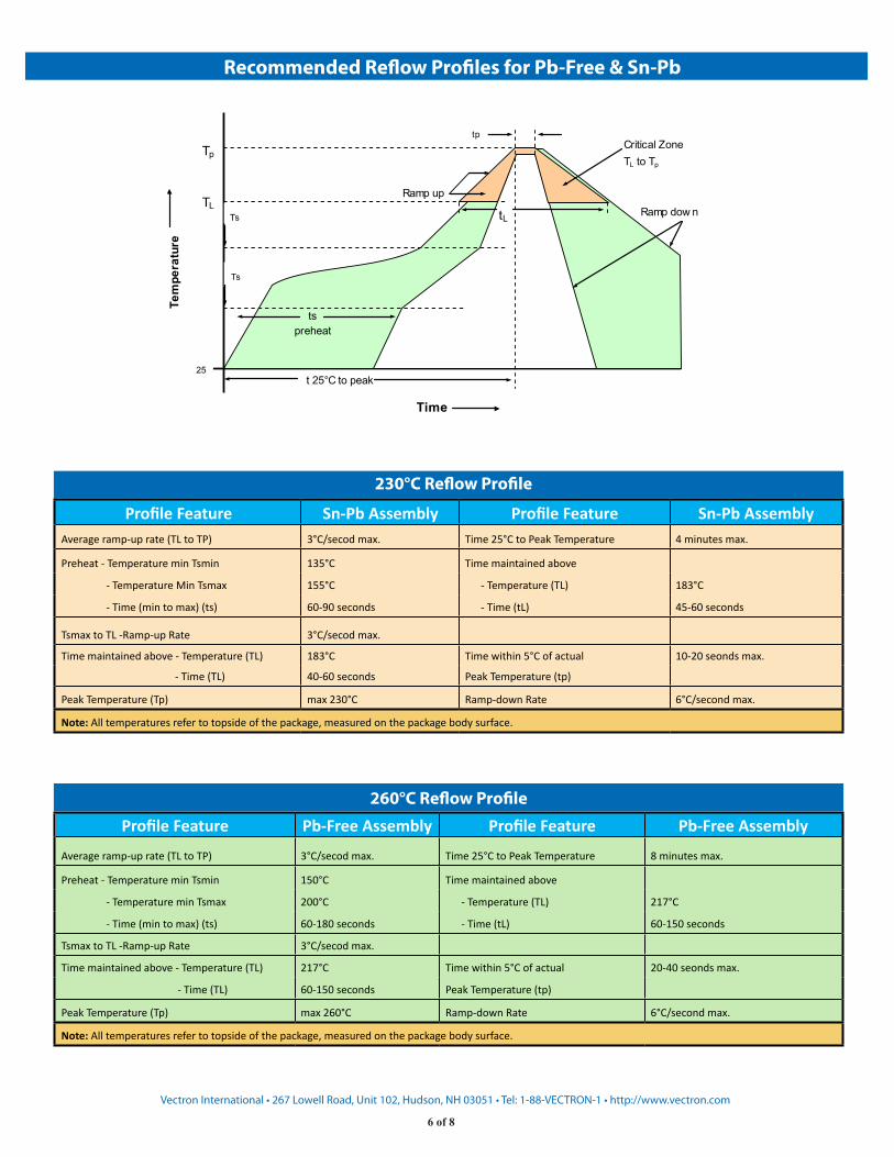
Recommended Reflow Profiles for Pb-Free & Sn-Pb
Vectron International • 267 Lowell Road, Unit 102, Hudson, NH 03051 • Tel: 1-88-VECTRON-1 • http://www.vectron.com
Critical ZoneTL to Tp
Ramp up
Ramp dow n
t 25°C to peak
Tp
Tem
pera
ture
TL
25
Time
Ts
min
Ts
ts preheat
tp
tL
Standard Shipping Method
Average ramp-up rate (TL to TP) 3°C/secod max. Time 25°C to Peak Temperature 8 minutes max.
Preheat - Temperature min Tsmin 150°C Time maintained above
- Temperature min Tsmax 200°C - Temperature (TL) 217°C
- Time (min to max) (ts) 60-180 seconds - Time (tL) 60-150 seconds
Tsmax to TL -Ramp-up Rate 3°C/secod max.
Time maintained above - Temperature (TL) 217°C Time within 5°C of actual 20-40 seonds max.
- Time (TL) 60-150 seconds Peak Temperature (tp)
Peak Temperature (Tp) max 260°C Ramp-down Rate 6°C/second max.
Note: All temperatures refer to topside of the package, measured on the package body surface.
Average ramp-up rate (TL to TP) 3°C/secod max. Time 25°C to Peak Temperature 4 minutes max.
Preheat - Temperature min Tsmin 135°C Time maintained above
- Temperature Min Tsmax 155°C - Temperature (TL) 183°C
- Time (min to max) (ts) 60-90 seconds - Time (tL) 45-60 seconds
Tsmax to TL -Ramp-up Rate 3°C/secod max.
Time maintained above - Temperature (TL) 183°C Time within 5°C of actual 10-20 seonds max.
- Time (TL) 40-60 seconds Peak Temperature (tp)
Peak Temperature (Tp) max 230°C Ramp-down Rate 6°C/second max.
Note: All temperatures refer to topside of the package, measured on the package body surface.
230°C Reflow Profile
260°C Reflow Profile
Profile Feature Sn-Pb Assembly Profile Feature Sn-Pb Assembly
Profile Feature Pb-Free Assembly Profile Feature Pb-Free Assembly
6 of 8
Vectron International • 267 Lowell Road, Unit 102, Hudson, NH 03051 • Tel: 1-88-VECTRON-1 • http://www.vectron.com
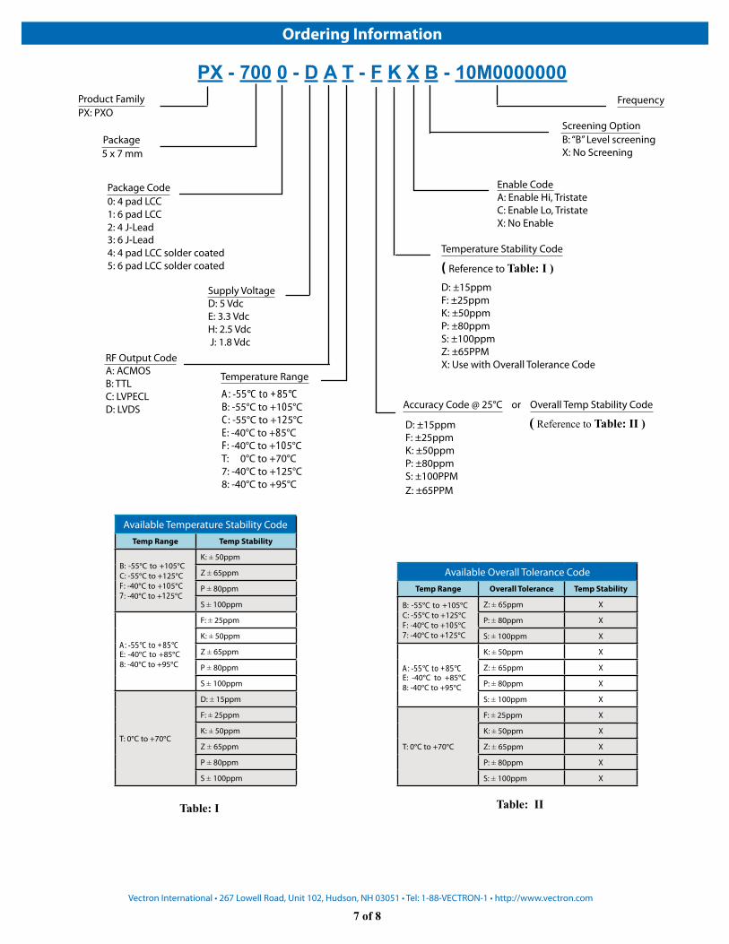
Ordering Information
PX - 700 0 - D A T - F K X B - 10M0000000Product FamilyPX: PXO
Package5 x 7 mm
Package Code0: 4 pad LCC1: 6 pad LCC
4: 4 pad LCC solder coated5: 6 pad LCC solder coated
Supply VoltageD: 5 VdcE: 3.3 VdcH: 2.5 Vdc J: 1.8 Vdc
Accuracy Code @ 25°C or Overall Temp Stability Code
Frequency
Screening OptionB: “B” Level screeningX: No Screening
RF Output CodeA: ACMOSB: TTLC: LVPECLD: LVDS
Temperature Stability Code
( Reference to Table: I )D: ±15ppmF: ±25ppmK: ±50ppmP: ±80ppmS: ±100ppmZ: ±65PPMX: Use with Overall Tolerance Code
Enable CodeA: Enable Hi, Tristate C: Enable Lo, Tristate X: No Enable
Available Temperature Stability CodeTemp Range Temp Stability
K: ± 50ppm
Z ± 65ppm
P ± 80ppm
S ± 100ppm
F: ± 25ppm
K: ± 50ppm
Z ± 65ppm
P ± 80ppm
S ± 100ppm
T: 0°C to +70°C
D: ± 15ppm
F: ± 25ppm
K: ± 50ppm
Z ± 65ppm
P ± 80ppm
S ± 100ppm
Available Overall Tolerance CodeTemp Range Overall Tolerance Temp Stability
Z: ± 65ppm X
P: ± 80ppm X
S: ± 100ppm X
K: ± 50ppm X
Z: ± 65ppm X
P: ± 80ppm X
S: ± 100ppm X
T: 0°C to +70°C
F: ± 25ppm X
K: ± 50ppm X
Z: ± 65ppm X
P: ± 80ppm X
S: ± 100ppm X
Table: I Table: II
D: ±15ppmF: ±25ppmK: ±50ppmP: ±80ppmS: ±100PPMZ: ±65PPM
( Reference to Table: II )
B: -55°C to +105°CC: -55°C to +125°C F: -40°C to +105°C 7: -40°C to +125°C
B: -55°C to +105°CC: -55°C to +125°C F: -40°C to +105°C 7: -40°C to +125°C
Temperature Range
A: -55°C to +85°CE: -40°C to +85°C8: -40°C to +95°C A: -55°C to +85°C
E: -40°C to +85°C8: -40°C to +95°C
A: -55°C to +85°CB: -55°C to +105°CC: -55°C to +125°CE: -40°C to +85°CF: -40°C to +105°CT: 0°C to +70°C7: -40°C to +125°C8: -40°C to +95°C
2: 4 J-Lead3: 6 J-Lead
7 of 8
