crystal structure and microstructure - iit kanpur crystal... · crystal structure and...
TRANSCRIPT
Crystal Structure and MicrostructureCrystal Structure and Microstructure
ANANDH SUBRAMANIAMMaterials Science and Engineering
INDIAN INSTITUTE OF TECHNOLOGY KANPURKanpur-
110016Ph: (+91) (512) 259 7215, Lab: (+91) (512) 259 7147
[email protected]://home.iitk.ac.in/~anandh/
19 Oct 2015MATERIALS SCIENCEMATERIALS SCIENCE
&&ENGINEERING ENGINEERING
AN INTRODUCTORY EAN INTRODUCTORY E--BOOKBOOKhttp://home.iitk.ac.in/~anandh/E-book.htmhttp://home.iitk.ac.in/~anandh/E-book.htm
A Learner’s GuideA LearnerA Learner’’s Guides Guide
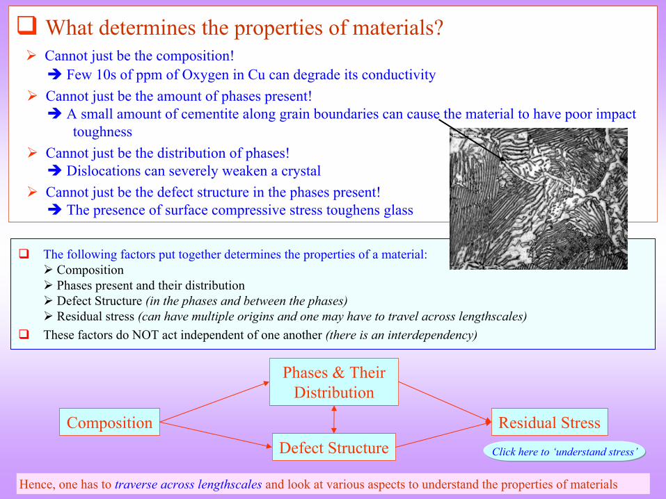
What determines the properties of materials?
Cannot just be the composition!
Few 10s of ppm
of Oxygen in Cu can degrade its conductivity
Cannot just be the amount of phases present!
A small amount of cementite
along grain boundaries can cause the material to have poor impact toughness
Cannot just be the distribution of phases!
Dislocations can severely weaken a crystal
Cannot just be the defect structure in the phases present!
The presence of surface compressive stress toughens glass
Composition
Phases & Their Distribution
Defect StructureResidual Stress
Hence, one has to traverse across lengthscales
and look at various aspects to understand the properties of materials
The following factors put together determines the properties of a material:
Composition
Phases present and their distribution
Defect Structure (in the phases and between the phases)
Residual stress (can have multiple origins and one may have to travel across lengthscales)
These factors do NOT act independent of one another (there is an interdependency)
Click here to ‘understand stress’
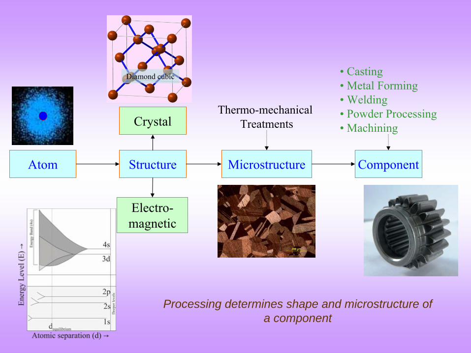
Atom Structure
Crystal
Electro-magnetic
Microstructure Component
Thermo-mechanical Treatments
• Casting• Metal Forming• Welding• Powder Processing• Machining
Processing determines shape and microstructure of a component
Diamond cubic
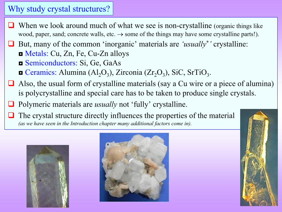
When we look around much of what we see is non-crystalline (organic things like wood, paper, sand; concrete walls, etc. some of the things may have some crystalline parts!).
But, many of the common ‘inorganic’
materials are ‘usually*’
crystalline: ◘
Metals:
Cu, Zn, Fe, Cu-Zn alloys
◘
Semiconductors:
Si, Ge, GaAs ◘
Ceramics: Alumina (Al2
O3
), Zirconia
(Zr2
O3
), SiC, SrTiO3
.
Also, the usual form of crystalline materials (say a Cu wire or a piece of alumina) is polycrystalline and special care has to be taken to produce single crystals.
Polymeric materials are usually not ‘fully’
crystalline.
The crystal structure directly influences the properties of the material
(as we have seen in the Introduction chapter many additional factors come in).
Why study crystal structures?
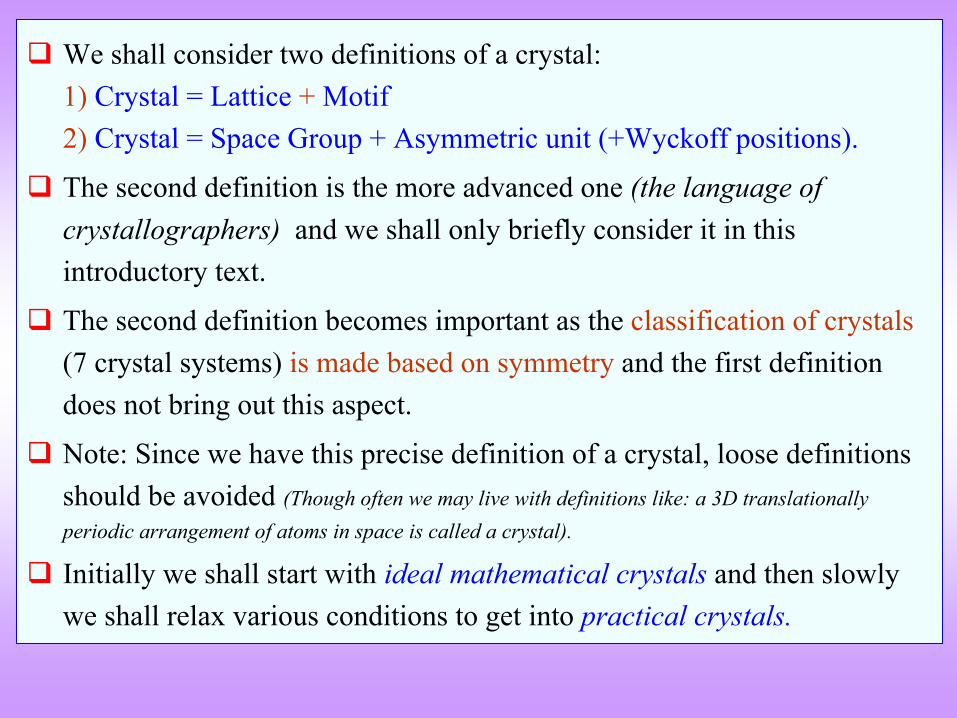
We shall consider two definitions of a crystal: 1)
Crystal = Lattice +
Motif
2) Crystal = Space Group + Asymmetric unit (+Wyckoff positions).
The second definition is the more advanced one (the language of crystallographers) and we shall only briefly consider it in this introductory text.
The second definition becomes important as the classification of crystals (7 crystal systems) is made based on symmetry
and the first definition
does not bring out this aspect.
Note: Since we have this precise definition of a crystal, loose definitions should be avoided (Though often we may live with definitions like: a 3D translationally periodic arrangement of atoms in space is called a crystal).
Initially we shall start with ideal mathematical crystals and then slowly we shall relax various conditions to get into practical crystals.
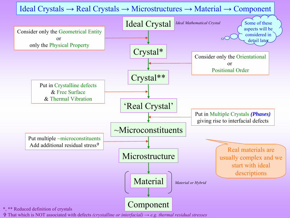
Ideal Crystal
Crystal*
~Microconstituents
‘Real Crystal’
Crystal**
Ideal Crystals → Real Crystals → Microstructures → Material → Component
Consider only the Geometrical Entityor
only the Physical Property
Put multiple ~microconstituentsAdd additional residual stress
Put in Crystalline defects & Free Surface
& Thermal Vibration
Consider only the Orientationalor
Positional Order
Put in Multiple Crystals
(Phases) giving rise to interfacial defects
Microstructure
*, ** Reduced definition of crystals
That which is NOT associated with defects (crystalline or interfacial) → e.g. thermal residual stresses
Some of these aspects will be considered in
detail later
Material
Component
Ideal Mathematical Crystal
Material or Hybrid
Real materials are usually complex and we
start with ideal descriptions
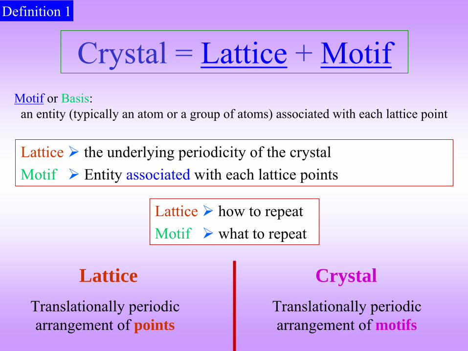
Lattice
the underlying periodicity of the crystalMotif
Entity associated
with each lattice points
Lattice
how to repeatMotif
what to repeat
Crystal = Lattice + MotifMotif
or Basis:
an entity (typically an atom or a group of atoms) associated with each lattice point
Definition 1
Translationally periodic arrangement of motifs
CrystalTranslationally periodic arrangement of points
Lattice
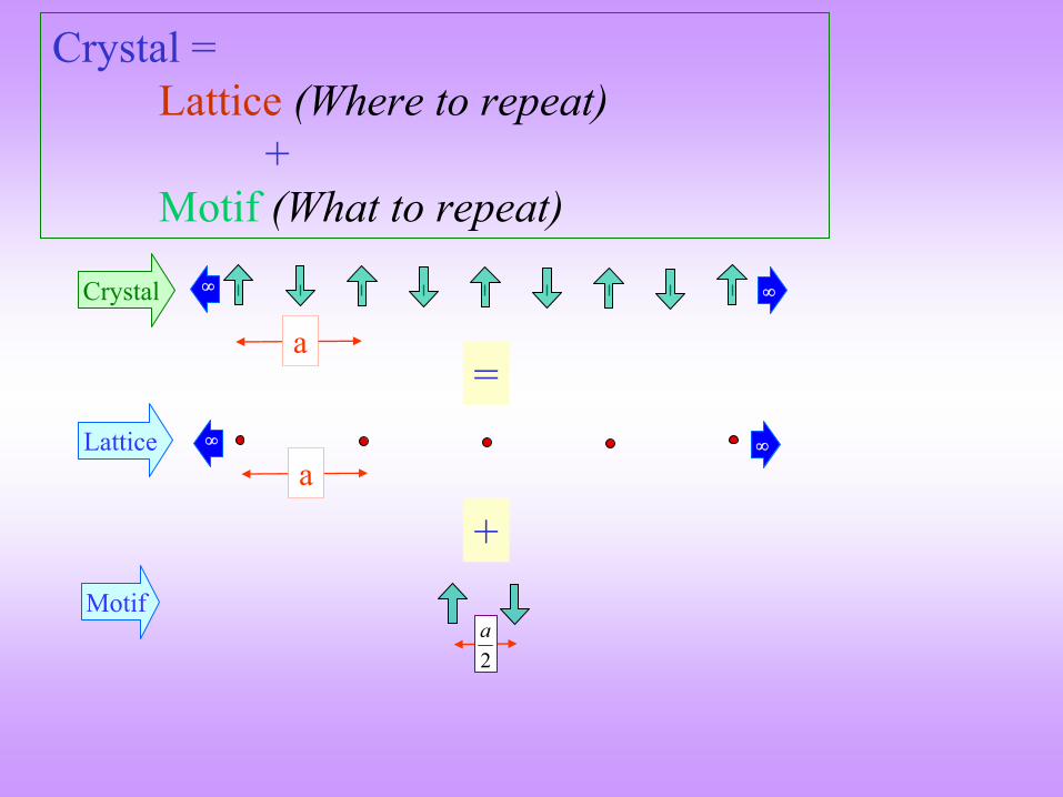
Crystal = Lattice (Where to repeat)
+ Motif (What to repeat)
=
+
a
a
2a
Lattice
Motif
Crystal
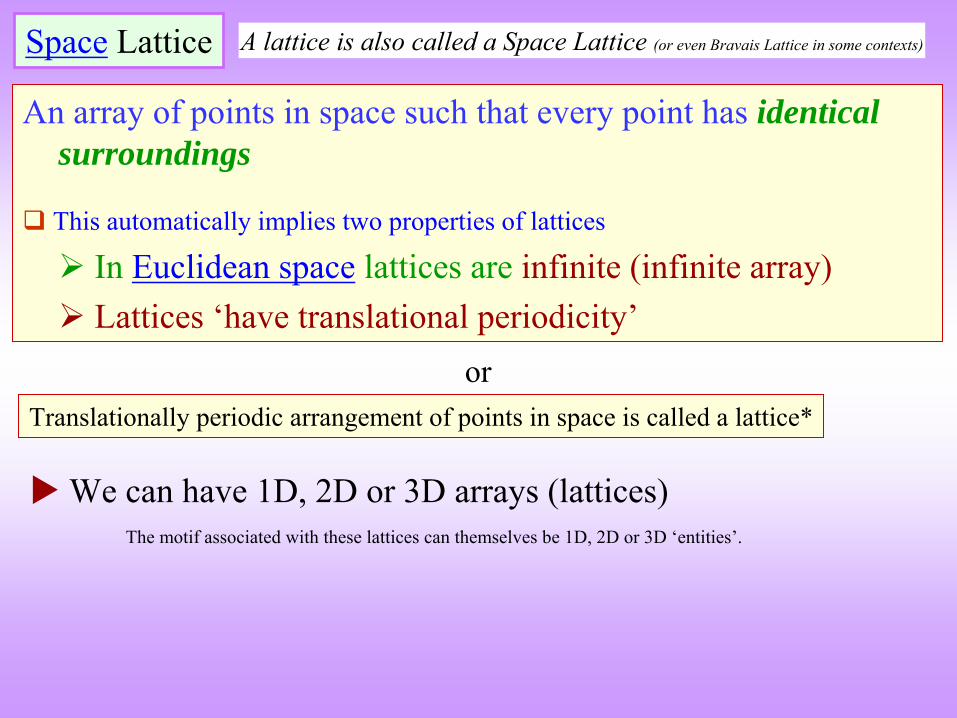
An array of points in space such that every point has identical surroundings
This automatically implies two properties of lattices
In Euclidean space
lattices are infinite (infinite array)
Lattices ‘have translational periodicity’
Space
Lattice
Translationally periodic arrangement of points in space is called a lattice*
or
A lattice is also called a Space Lattice (or even Bravais
Lattice in some contexts)
We can have 1D, 2D or 3D arrays (lattices)The motif associated with these lattices can themselves be 1D, 2D or 3D ‘entities’.
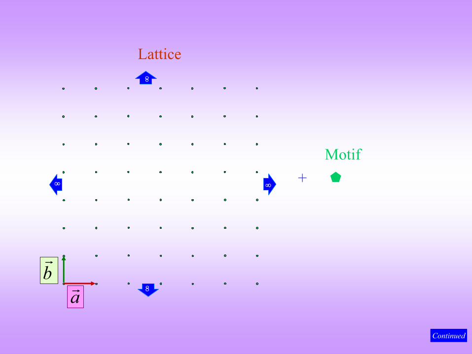
+
Lattice
Motif
ab
Continued
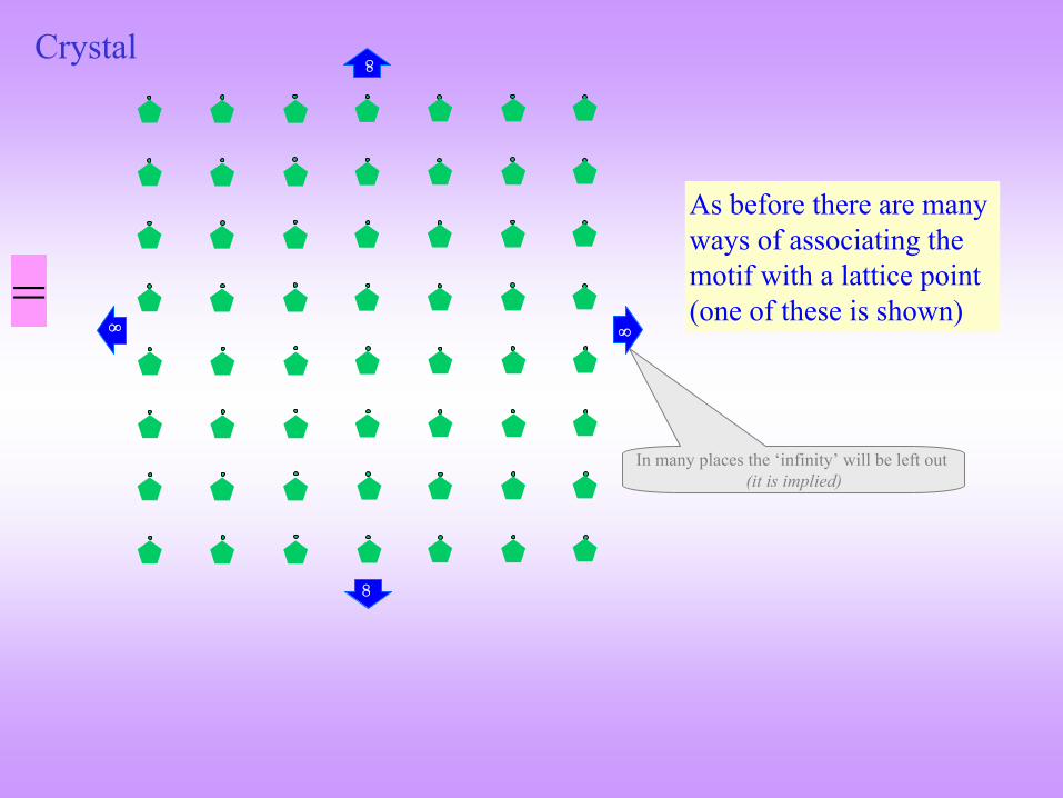
Crystal
=
As before there are many ways of associating the motif with a lattice point (one of these is shown)
In many places the ‘infinity’
will be left out (it is implied)
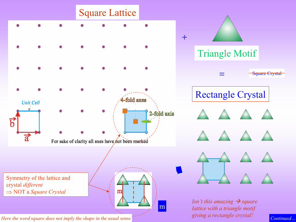
+
Square Lattice
Triangle Motif
=
Rectangle Crystal
Continued…
Symmetry of the lattice and crystal different NOT a Square Crystal
Square Crystal
Here the word square does not imply the shape in the usual sense
mIsn’t this amazing square lattice with a triangle motif giving a rectangle crystal!

Lattices
can be constructed using translation alone
The definition (& classification) of Crystals is based on symmetry
and NOT on
the geometry of the unit cell (as often one might feel after reading some books!)
Crystals based on a particular lattice can have symmetry:
equal to that of the lattice or
lower than that of the lattice
Based on symmetry
crystals are classified into seven
types/categories/systems
known as the SEVEN CRYSTAL SYSTEMS
We can put
all possible crystals into 7
boxes based on symmetry
Crystal system
Symmetry operators
acting at a point can combine in 32
distinct ways to give the 32 point groups
Lattices have 7 distinct point group symmetries which correspond
to the SEVEN CRYSTAL SYSTEMS
Alternate view Advanced concept: readers can return to this point later!
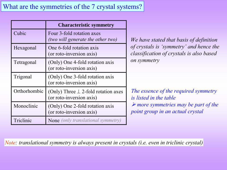
What are the symmetries of the 7 crystal systems?
Characteristic symmetry Cubic Four 3-fold rotation axes
(two will generate the other two) Hexagonal One 6-fold rotation axis
(or roto-inversion axis) Tetragonal (Only) One 4-fold rotation axis
(or roto-inversion axis) Trigonal (Only) One 3-fold rotation axis
(or roto-inversion axis) Orthorhombic (Only) Three 2-fold rotation axes
(or roto-inversion axis) Monoclinic (Only) One 2-fold rotation axis
(or roto-inversion axis) Triclinic None
Note: translational symmetry is always present in crystals (i.e. even in triclinic crystal)
We have stated that basis of definition of crystals is ‘symmetry’
and hence the
classification of crystals is also based on symmetry
The essence of the required symmetry is listed in the table more symmetries may be part of the point group in an actual crystal
(only translational symmetry)
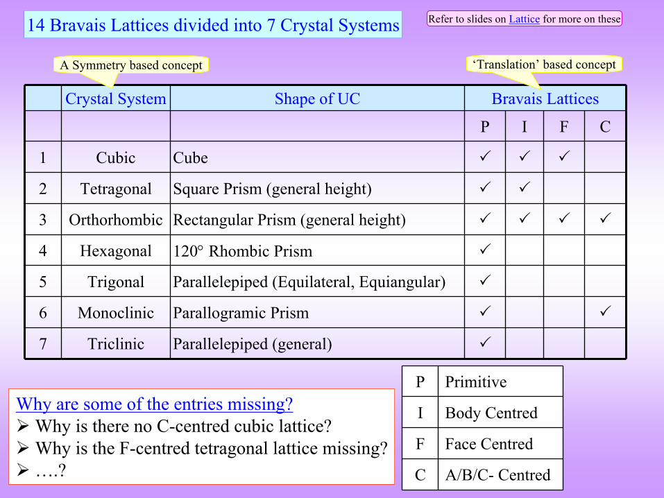
Crystal System Shape of UC Bravais
Lattices
P I F C
1 Cubic Cube
2 Tetragonal Square Prism (general height)
3 Orthorhombic Rectangular Prism (general height)
4 Hexagonal 120
Rhombic Prism
5 Trigonal Parallelepiped (Equilateral, Equiangular)
6 Monoclinic Parallogramic
Prism
7 Triclinic Parallelepiped (general)
Why are some of the entries missing?
Why is there no C-centred cubic lattice?
Why is the F-centred tetragonal lattice missing?
….?
14 Bravais
Lattices divided into 7 Crystal Systems
P Primitive
I Body Centred
F Face Centred
C A/B/C-
Centred
A Symmetry based concept
Refer to slides on Lattice
for more on these
‘Translation’
based concept
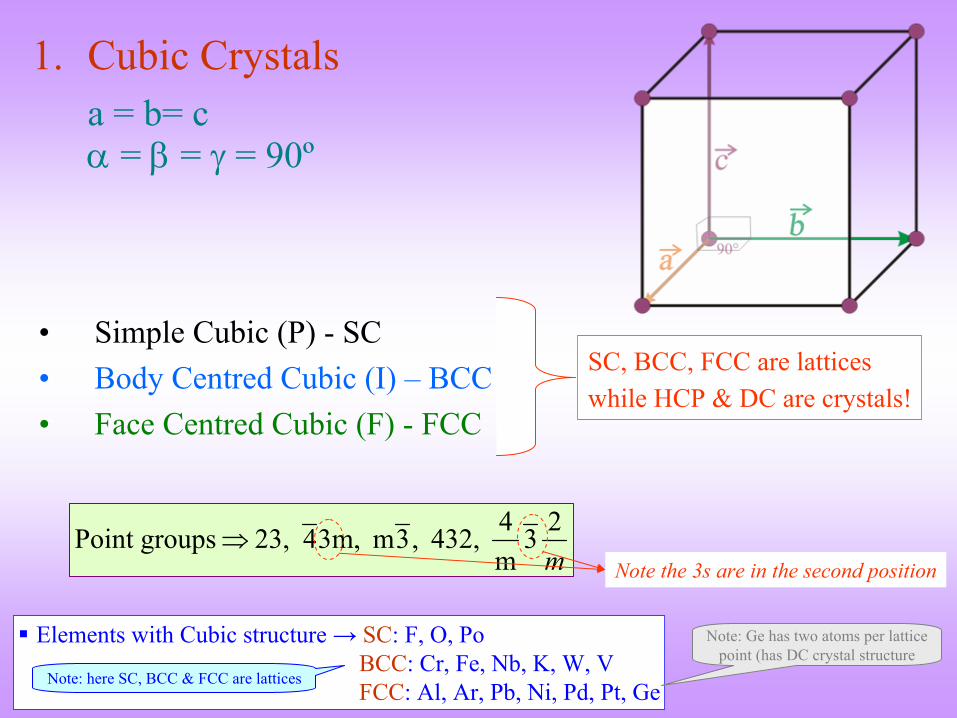
1.
Cubic Crystalsa = b= c
=
=
= 90º
m23
m4 432, ,3m 3m,4 23, groupsPoint
Note the 3s are in the second position
SC, BCC, FCC are latticeswhile HCP & DC are crystals!
•
Simple Cubic (P) -
SC•
Body Centred Cubic (I) –
BCC
•
Face Centred Cubic (F) -
FCC
Elements with Cubic structure → SC: F, O, Po
BCC: Cr, Fe, Nb, K, W, V FCC: Al, Ar, Pb, Ni, Pd, Pt, Ge
Note: here SC, BCC & FCC are lattices
Note: Ge
has two atoms per lattice point (has DC crystal structure
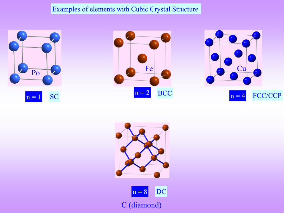
Examples of elements with Cubic Crystal Structure
Po
n = 1 n = 2 n = 4
Fe Cu
BCC FCC/CCPSC
C (diamond)
n = 8 DC
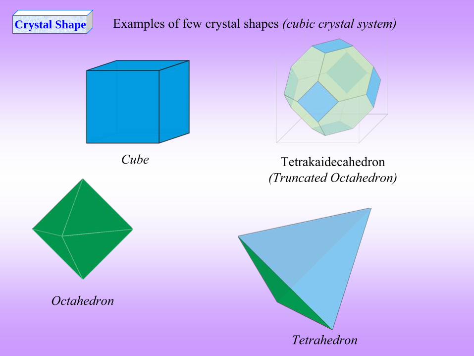
Tetrakaidecahedron(Truncated Octahedron)
Octahedron
Cube
Crystal Shape
Tetrahedron
Examples of few crystal shapes (cubic crystal system)
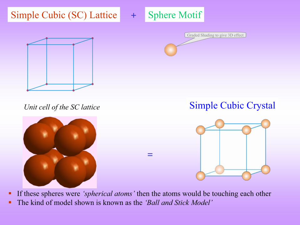
+Simple Cubic (SC) Lattice Sphere Motif
=
Simple Cubic Crystal
Graded Shading to give 3D effect
Unit cell of the SC lattice
If these spheres were ‘spherical atoms’
then the atoms would be touching each other
The kind of model shown is known as the ‘Ball and Stick Model’
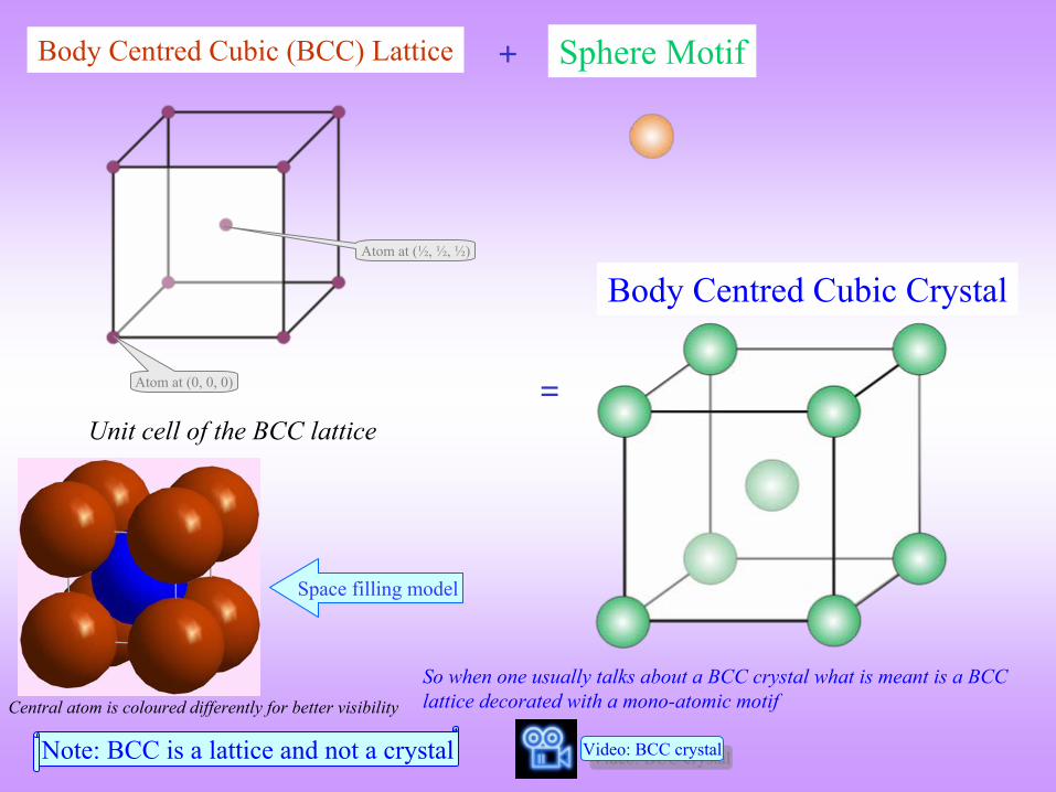
+Body Centred Cubic (BCC) Lattice Sphere Motif
=
Body Centred Cubic Crystal
Note: BCC is a lattice and not a crystal
So when one usually talks about a BCC crystal what is meant is a
BCC lattice decorated with a mono-atomic motif
Unit cell of the BCC lattice
Atom at (½, ½, ½)
Atom at (0, 0, 0)
Space filling model
Central atom is coloured
differently for better visibility
Video: BCC crystalVideo: BCC crystal
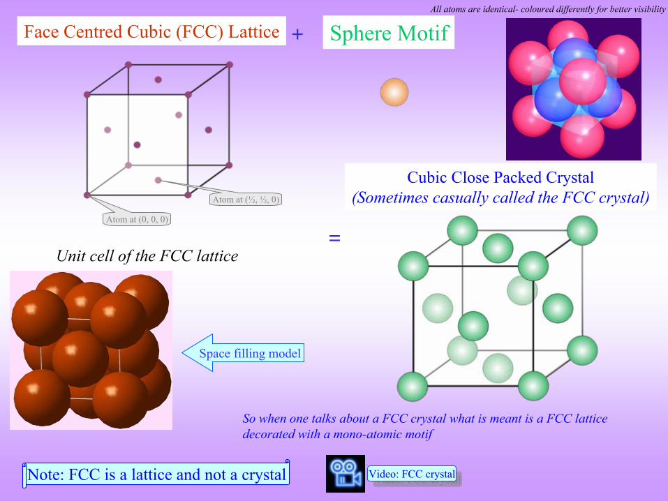
+Face Centred Cubic (FCC) Lattice Sphere Motif
=
Cubic Close Packed Crystal (Sometimes casually called the FCC crystal)
Note: FCC is a lattice and not a crystal
So when one talks about a FCC crystal what is meant is a FCC lattice decorated with a mono-atomic motif
Atom at (½, ½, 0)
Atom at (0, 0, 0)
Unit cell of the FCC lattice
Space filling model
Video: FCC crystalVideo: FCC crystal
All atoms are identical-
coloured
differently for better visibility
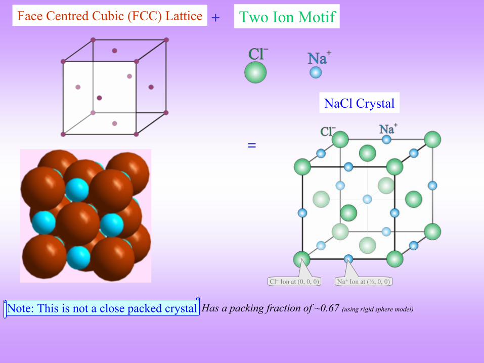
+Face Centred Cubic (FCC) Lattice Two Ion Motif
=
NaCl
Crystal
Note: This is not a close packed crystal Has a packing fraction of ~0.67 (using rigid sphere model)
Na+
Ion at (½, 0, 0)Cl
Ion at (0, 0, 0)
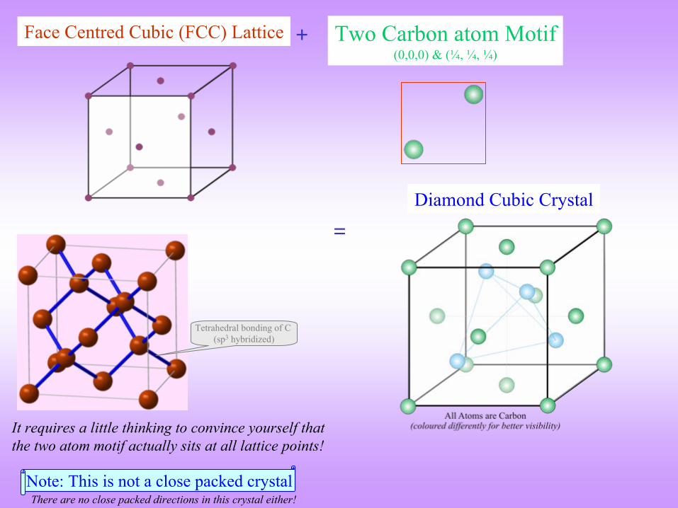
+Face Centred Cubic (FCC) Lattice Two Carbon atom Motif (0,0,0) & (¼, ¼, ¼)
=Diamond Cubic Crystal
Note: This is not a close packed crystal
It requires a little thinking to convince yourself that the two atom motif actually sits at all lattice points!
There are no close packed directions in this crystal either!
Tetrahedral bonding of C (sp3
hybridized)
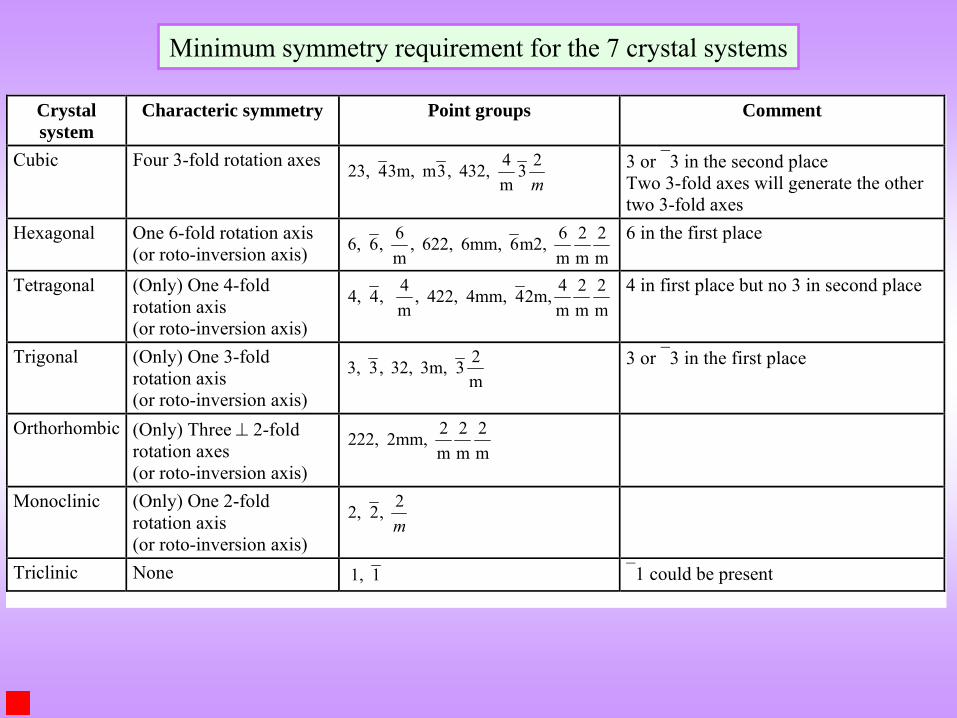
Minimum symmetry requirement for the 7 crystal systems
Crystal system
Characteric symmetry Point groups Comment
Cubic Four 3-fold rotation axes m23
m4 432, ,3m 3m,4 23,
3 or 3 in the second place Two 3-fold axes will generate the other two 3-fold axes
Hexagonal One 6-fold rotation axis (or roto-inversion axis) m
2m2
m6 m2,6 6mm, 622, ,
m6 ,6 6, 6 in the first place
Tetragonal (Only) One 4-fold rotation axis (or roto-inversion axis)
m2
m2
m42m,4 4mm, 422, ,
m4 ,4 4, 4 in first place but no 3 in second place
Trigonal (Only) One 3-fold rotation axis (or roto-inversion axis)
m23 3m, 32, ,3 3,
3 or 3 in the first place
Orthorhombic (Only) Three 2-fold rotation axes (or roto-inversion axis)
m2
m2
m2 2mm, 222,
Monoclinic (Only) One 2-fold rotation axis (or roto-inversion axis)
m2 ,2 2,
Triclinic None 1 1, 1 could be present

SUMMARYSUMMARY
Crystal
= Lattice
+ Motif
There are 14
Bravais
lattices in 3D (which are based on translation)
Motif is any entity (or entities) which is positioned identically with respect to every lattice point
There are 32 different ways in which symmetries (rotation, roto-inversion, mirror, inversion) can combine at a point called the 32 point groups
These Bravais
lattices have 7 different symmetries which correspond to the 7 crystal systems
Conventionally, 7 different unit cells
are chosen for these 7 crystal systems
Real crystals are ‘defected’
in many ways so that some of the symmetries present
in an ideal crystal are ‘disturbed’
(either locally or globally).
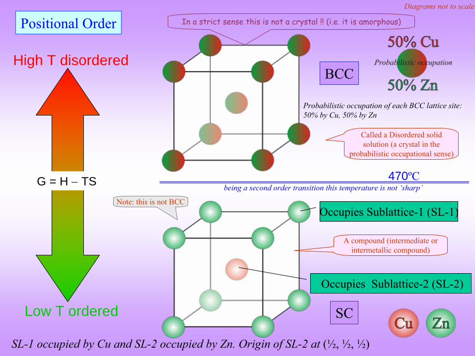
Positional Order
G = H
TS
High T disordered
Low T ordered
470ºC being a second order transition this temperature is not ‘sharp’
Occupies Sublattice-1 (SL-1)
Occupies Sublattice-2 (SL-2)
BCC
SC
SL-1 occupied by Cu and SL-2 occupied by Zn. Origin of SL-2 at (½, ½, ½)
In a strict sense this is not a crystal !! (i.e. it is amorphous)
Probabilistic occupation of each BCC lattice site: 50% by Cu, 50% by Zn
Diagrams not to scale
Note: this is not BCC
Called a Disordered solid solution (a crystal in the
probabilistic occupational sense)
A compound (intermediate or intermetallic compound)

n = 2
Fe
Some examples of BCC crystals
Funda
Check Do BCC crystals have 2 atoms per cell?
n = 58
Mn
cI58-Brass
Cu5
Zn8n = 52
A: need NOT
In the conventional (natural choice of UC) there are no atoms
at (0,0,0) and (½,
½,
½)!!
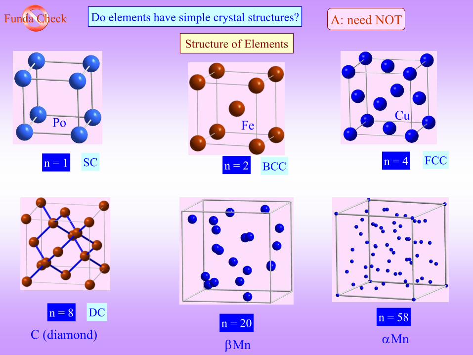
Po
n = 1 n = 2 n = 4
n = 58
Mn
Structure of Elements
Fe
C (diamond)
n = 8
Cu
n = 20
Mn
BCC FCCSC
DC
Funda
Check Do elements have simple crystal structures? A: need NOT
MICROSTRUCTUREMICROSTRUCTURE
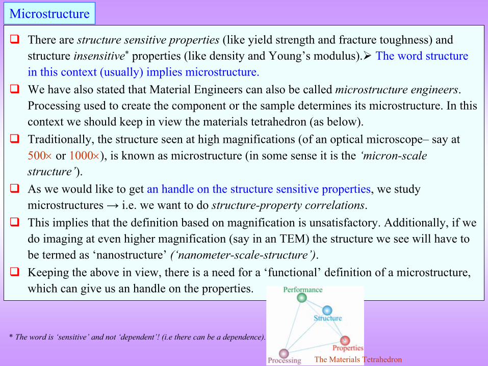
There are structure sensitive properties (like yield strength and fracture toughness) and structure insensitive*
properties (like density and Young’s modulus).
The word structure in this context (usually) implies microstructure.
We have also stated that Material Engineers can also be called microstructure engineers. Processing used to create the component or the sample determines
its microstructure. In this
context we should keep in view the materials tetrahedron (as below).
Traditionally, the structure seen at high magnifications (of an optical microscope–
say at
500
or 1000), is known as microstructure (in some sense it is the ‘micron-scale structure’).
As we would like to get an handle on the structure sensitive properties, we study microstructures → i.e. we want to do structure-property correlations.
This implies that the definition based on magnification is unsatisfactory. Additionally, if we do imaging at even higher magnification (say in an TEM) the structure we see will have to be termed as ‘nanostructure’
(‘nanometer-scale-structure’).
Keeping the above in view, there is a need for a ‘functional’
definition of a microstructure,
which can give us an handle on the properties.
Microstructure
The Materials Tetrahedron
* The word is ‘sensitive’
and not ‘dependent’! (i.e
there can be a dependence).
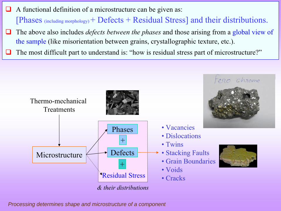
Microstructure
Thermo-mechanical Treatments
Phases
Defects+
• Vacancies• Dislocations• Twins• Stacking Faults• Grain Boundaries• Voids• Cracks
+Residual Stress
Processing determines shape and microstructure of a component
& their distributions
A functional definition of a microstructure can be given as:
[Phases (including morphology) + Defects + Residual Stress] and their distributions.
The above also includes defects between the phases and those arising from a
global view of
the sample (like misorientation between grains, crystallographic texture, etc.).
The most difficult part to understand is: “how is residual stress part of microstructure?”
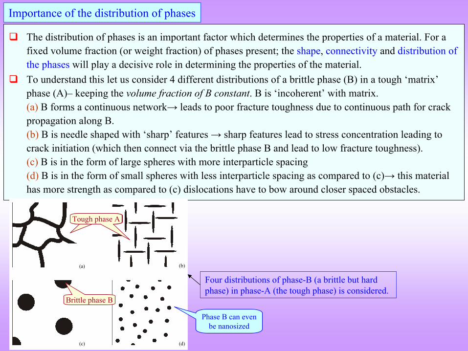
The distribution of phases is an important factor which determines the properties of a material. For a fixed volume fraction (or weight fraction) of phases present; the shape, connectivity
and distribution of the phases
will play a decisive role in determining the properties of the material.
To understand this let us consider 4 different distributions of a brittle phase (B) in a tough ‘matrix’
phase (A)–
keeping the volume fraction of B constant. B is ‘incoherent’
with matrix. (a) B forms a continuous network→ leads to poor fracture toughness due to continuous path for crack propagation along B.
(b)
B is needle shaped with ‘sharp’
features → sharp features lead to stress concentration leading to crack initiation (which then connect via the brittle phase B and
lead to low fracture toughness). (c)
B is in the form of large spheres with more interparticle
spacing (d)
B is in the form of small spheres with less interparticle
spacing as compared to (c)→ this material has more strength as compared to (c) dislocations have to bow around closer spaced obstacles.
Importance of the distribution of phases
(a) (b)
(c) (d)
Four distributions of phase-B (a brittle but hard phase) in phase-A (the tough phase) is considered.
Phase B can even be nanosized
Touch phase ATough phase A
Brittle phase B
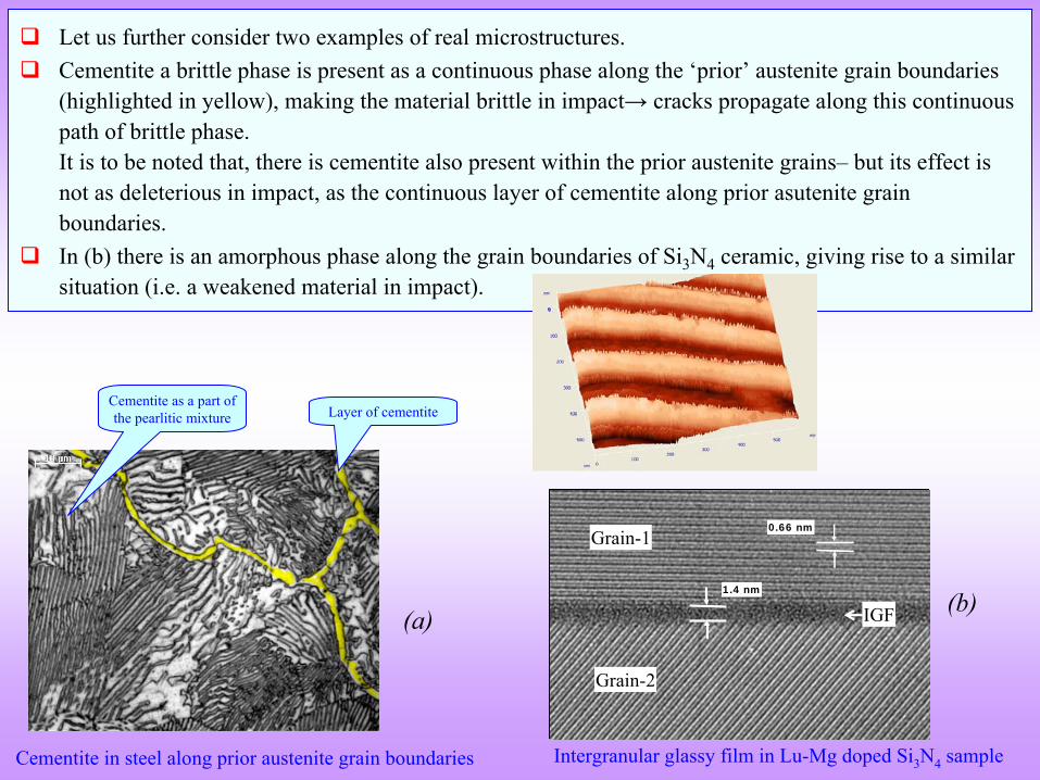
Let us further consider two examples of real microstructures.
Cementite
a brittle phase is present as a continuous phase along the ‘prior’
austenite grain boundaries (highlighted in yellow), making the material brittle in impact→ cracks propagate along this continuous path of brittle phase.
It is to be noted that, there is cementite
also present within the prior austenite grains–
but its effect is not as deleterious in impact, as the continuous layer of cementite
along prior asutenite
grain boundaries.
In (b) there is an amorphous phase along the grain boundaries of
Si3
N4
ceramic, giving rise to a similar situation (i.e. a weakened material in impact).
0.66 nm
1.4 nm
IGF
Grain-1
Grain-2
0.66 nm
1.4 nm
IGF
Grain-1
Grain-2
Cementite
in steel along prior austenite grain boundaries Intergranular
glassy film in Lu-Mg doped Si3
N4
sample
(a)(b)
Layer of cementiteCementite
as a part of the pearlitic
mixture
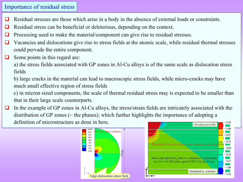
Residual stresses are those which arise in a body in the absence
of external loads or constraints.
Residual stress can be beneficial or deleterious, depending on the context.
Processing used to make the material/component can give rise to residual stresses.
Vacancies and dislocations give rise to stress fields at the atomic scale, while residual thermal stresses could pervade the entire component.
Some points in this regard are: a) the stress fields associated with GP zones in Al-Cu alloys is of the same scale as dislocation stress fields
b) large cracks in the material can lead to macroscopic stress fields, while micro-cracks may have much small effective region of stress fields
c) in micron sized components, the scale of thermal residual stress may is expected to be smaller than that in their large scale counterparts.
In the example of GP zones in Al-Cu alloys, the stress/strain fields are intricately associated with the distribution of GP zones (~ the phases); which further highlights the importance of adopting a definition of microstructure as done in here.
Importance of residual stress
Plot of x stress contours
Edge dislocation stress field
+ 2.44
+ 1.00
+ 0.67
+ 0.33
0.00
− 0.33
− 0.67
− 1.00
− 1.16x
y
z
All values are in GPa
Simulated σy contours
Stress state (plot of y) due to a coherent -Fe precipitate in a Cu–2 wt.%Fe alloy aged at 700 C for (a) 30 min.
+ 2.44
+ 1.00
+ 0.67
+ 0.33
0.00
− 0.33
− 0.67
− 1.00
− 1.16
+ 2.44
+ 1.00
+ 0.67
+ 0.33
0.00
− 0.33
− 0.67
− 1.00
+ 2.44
+ 1.00
+ 0.67
+ 0.33
0.00
− 0.33
− 0.67
− 1.00
− 1.16x
y
z x
y
z
y
zz
All values are in GPa
Simulated σy contours
Stress state (plot of y) due to a coherent -Fe precipitate in a Cu–2 wt.%Fe alloy aged at 700 C for (a) 30 min.
Residual stresses due to an coherent precipitate
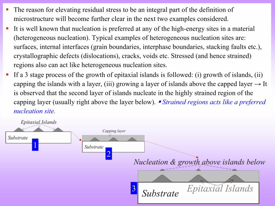
The reason for elevating residual stress to be an integral part of the definition of microstructure will become further clear in the next two examples considered.
It is well known that nucleation is preferred at any of the high-energy sites in a material (heterogeneous nucleation). Typical examples of heterogeneous nucleation sites are: surfaces, internal interfaces (grain boundaries, interphase
boundaries, stacking faults etc.),
crystallographic defects (dislocations), cracks, voids etc. Stressed (and hence strained) regions also can act like heterogeneous nucleation sites.
If a 3 stage process of the growth of epitaxial islands is followed: (i) growth of islands, (ii) capping the islands with a layer, (iii) growing a layer of islands above the capped layer → It is observed that the second layer of islands nucleate in the highly strained region of the capping layer (usually right above the layer below). Strained regions acts like a preferred nucleation site.
3
21