crystallography and structure lec. (3) 1. overview: crystal structure – matter assumes a periodic...
TRANSCRIPT

Crystallography and Structure
Lec. (3)
1

Overview:
Crystal Structure – matter assumes a periodic shapeNon-Crystalline or Amorphous “structures”
exhibit no long range periodic shapesXtal Systems – not structures but potentialsFCC, BCC and HCP – common Xtal
Structures for metals Point, Direction and Planer ID’ing in Xtals X-Ray Diffraction and Xtal Structure
2

• Non dense, random packing
• Dense, ordered packing
Dense, ordered packed structures tend to have lower energies & thus are more stable.
Energy and PackingEnergy
r
typical neighbor bond length
typical neighbor bond energy
Energy
r
typical neighbor bond length
typical neighbor bond energy
3

Means: periodic arrangement of atoms/ions over large atomic distances Leads to structure displaying
long-range order that is Measurable and Quantifiable
All metals, many ceramics, and some polymers exhibit this “High Bond Energy” and a More
Closely Packed Structure
CRYSTAL STRUCTURES
4

Amorphous Materials
These less densely packed lower bond energy “structures” can be found in Metals are observed in
Ceramic GLASS and many “plastics”
Are materials lacking long range order
5
Crystal Systems – Some Definitional information
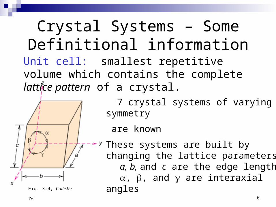
7 crystal systems of varying symmetry
are known
These systems are built by changing the lattice parameters:
a, b, and c are the edge lengths, , and are interaxial angles
Fig. 3.4, Callister 7e.
Unit cell: smallest repetitive volume which contains the complete lattice pattern of a crystal.
6

General Unit Cell Discussion• For any lattice, the unit cell &, thus,
the entire lattice, is UNIQUELY determined by 6 constants (figure):
a, b, c, α, β and γwhich depend on lattice geometry.
• As we’ll see, we sometimes want to calculate the number of atoms in a unit cell. To do this, imagine stacking hard spheres centered at each lattice point & just touching each neighboring sphere. Then, for the cubic lattices, only 1/8 of each lattice point in a unit cell assigned to that cell. In the cubic lattice in the figure, each unit cell is associated with (8) (1/8) = 1 lattice point.
7

Primitive Unit Cells & Primitive Lattice Vectors• In general, a Primitive Unit
Cell is determined by the parallelepiped formed by the Primitive Vectors a1 ,a2, & a3 such that there is no cell of smaller volume that can be used as a building block for the crystal structure.
• As we’ve discussed, a Primitive Unit Cell can be repeated to fill space by periodic repetition of it through the translation vectors
T = n1a1 + n2a2 + n3a3.
• The Primitive Unit Cell volume can be found by vector manipulation:
V = a1(a2 a3) • For the cubic unit cell in
the figure, V = a38

Primitive Unit Cells• Note that, by definition, the Primitive Unit Cell must
contain ONLY ONE lattice point.• There can be different choices for the Primitive Lattice
Vectors, but the Primitive Cell volume must be independent of that choice.
A 2 Dimensional Example!
P = Primitive Unit CellNP = Non-Primitive Unit Cell
9

2-Dimensional Unit CellsArtificial Example: “NaCl”
Lattice points are points with identical environments.
10

2-Dimensional Unit Cells: “NaCl”
The choice of origin is arbitrary - lattice points need not be atoms - but the unit cell size must always be the same.
11

2-Dimensional Unit Cells: “NaCl”These are also unit cells -
it doesn’t matter if the origin is at Na or Cl !
12

2-Dimensional Unit Cells: “NaCl”These are also unit cells -
the origin does not have to be on an atom!
13
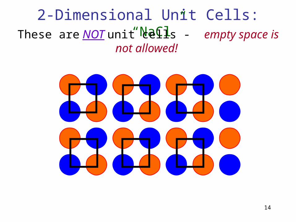
2-Dimensional Unit Cells: “NaCl”
These are NOT unit cells - empty space is not allowed!
14

2-Dimensional Unit Cells: “NaCl”
In 2 dimensions, these are unit cells – in 3 dimensions, they would not be.
15

Crystal Systems
Crystal structures are divided into groups according to unit cell geometry (symmetry).
16

• Tend to be densely packed.
• Reasons for dense packing:- Typically, only one element is present, so all atomic radii are the same.- Metallic bonding is not directional.- Nearest neighbor distances tend to be small in order to lower bond energy.- Electron cloud shields cores from each other
• Have the simplest crystal structures.
We will examine three such structures (those of engineering importance) called: FCC, BCC and HCP – with a nod to Simple Cubic
Metallic Crystal Structures
17

Crystal Structure of Metals – of engineering interest
18
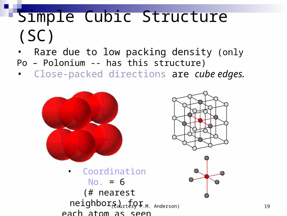
• Rare due to low packing density (only Po – Polonium -- has this structure)• Close-packed directions are cube edges.
• Coordination No. = 6 (# nearest neighbors) for each atom as seen
(Courtesy P.M. Anderson)
Simple Cubic Structure (SC)
19
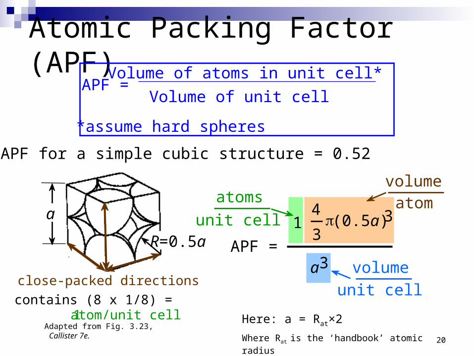
• APF for a simple cubic structure = 0.52
APF = a3
4
3 p (0.5a) 31
atoms
unit cellatom
volume
unit cell
volume
Atomic Packing Factor (APF)APF =
Volume of atoms in unit cell*
Volume of unit cell
*assume hard spheres
Adapted from Fig. 3.23, Callister 7e.
close-packed directions
a
R=0.5a
contains (8 x 1/8) = 1 atom/unit cell Here: a = Rat×2
Where Rat is the ‘handbook’ atomic radius 20
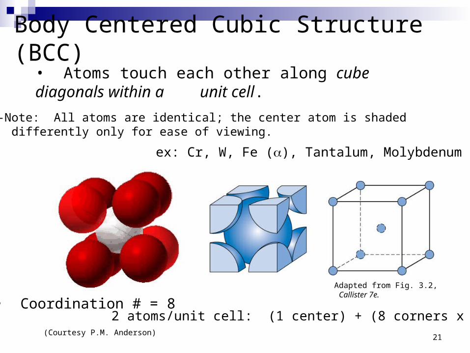
• Coordination # = 8
Adapted from Fig. 3.2, Callister 7e.
(Courtesy P.M. Anderson)
• Atoms touch each other along cube diagonals within a unit cell.
--Note: All atoms are identical; the center atom is shaded differently only for ease of viewing.
Body Centered Cubic Structure (BCC)
ex: Cr, W, Fe (), Tantalum, Molybdenum
2 atoms/unit cell: (1 center) + (8 corners x 1/8)
21

Atomic Packing Factor: BCC
a
APF =
4
3p ( 3a/4)32
atoms
unit cell atom
volume
a3unit cell
volume
length = 4R =Close-packed directions:
3 a
• APF for a body-centered cubic structure = 0.68
Adapted from Fig. 3.2(a), Callister 7e.
a 2
a 3
22

• Coordination # = 12
Adapted from Fig. 3.1, Callister 7e.
(Courtesy P.M. Anderson)
• Atoms touch each other along face diagonals.--Note: All atoms are identical; the face-centered atoms are shaded differently only for ease of viewing.
Face Centered Cubic Structure (FCC)
ex: Al, Cu, Au, Pb, Ni, Pt, Ag
4 atoms/unit cell: (6 face x ½) + (8 corners x 1/8)23

• APF for a face-centered cubic structure = 0.74
Atomic Packing Factor: FCC
The maximum achievable APF!
APF =
4
3 p ( 2a/4)34
atoms
unit cell atom
volume
a3unit cell
volume
Close-packed directions: length = 4R = 2 a
Unit cell contains: 6 x 1/2 + 8 x 1/8 = 4 atoms/unit cell
Adapted fromFig. 3.1(a),Callister 7e.
(a = 22*R)
24
25
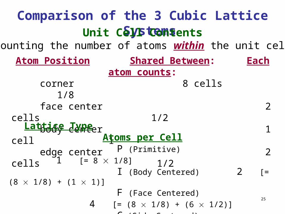
Atom Position Shared Between: Each atom counts: corner 8 cells 1/8 face center 2 cells 1/2 body center 1 cell 1 edge center 2 cells 1/2
Lattice Type Atoms per Cell P (Primitive) 1 [= 8 1/8]
I (Body Centered) 2 [= (8 1/8) + (1 1)]
F (Face Centered) 4 [= (8 1/8) + (6 1/2)]
C (Side Centered) 2 [= (8 1/8) + (2 1/2)]
Counting the number of atoms within the unit cell
Comparison of the 3 Cubic Lattice SystemsUnit Cell Contents
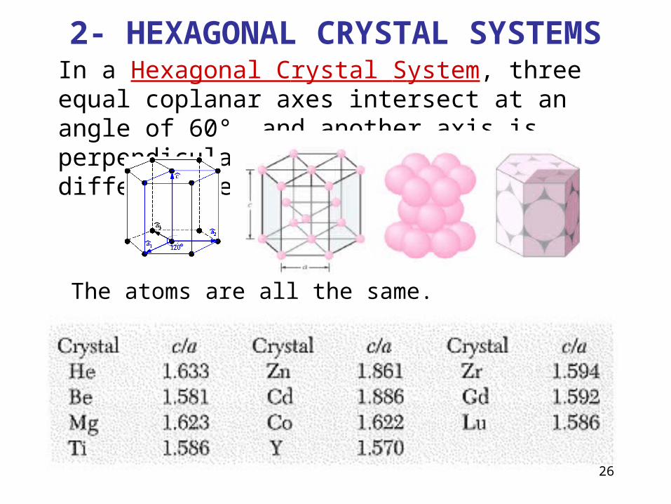
In a Hexagonal Crystal System, three equal coplanar axes intersect at an angle of 60°, and another axis is perpendicular to the others and of a different length.
2- HEXAGONAL CRYSTAL SYSTEMS
The atoms are all the same.
26

• Coordination # = 12
• ABAB... Stacking Sequence
• APF = 0.74
• 3D Projection • 2D Projection
Adapted from Fig. 3.3(a), Callister 7e.
Hexagonal Close-Packed Structure (HCP)
6 atoms/unit cell
ex: Cd, Mg, Ti, Zn
• c/a = 1.633 (ideal)
c
a
A sites
B sites
A sitesBottom layer
Middle layer
Top layer
27

Crystal Structure 28
Bravais Lattice :Hexagonal LatticeHe, Be, Mg, Hf, Re(Group II elements)
ABABAB Type of Stacking
a = bAngle between a & b = 120°
c = 1.633a, basis:
(0,0,0) (2/3a ,1/3a,1/2c)
Hexagonal Close Packed (HCP) Lattice
28
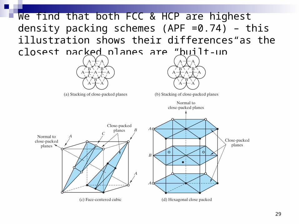
We find that both FCC & HCP are highest density packing schemes (APF =0.74) – this illustration shows their differences as the closest packed planes are “built-up”
29

Crystal Structure 30
A A
AA
AA
A
AAA
AA
AAA
AAA
B B
B
B
B B
B
B
B
BB
C C C
CC
C
C
C C C
Sequence ABABAB..-hexagonal close pack
Sequence ABCABCAB..-face centered cubic close pack
Close pack
B
AA
AA
A
A
A
A A
B
B B
Sequence AAAA…- simple cubic
Sequence ABAB…- body centered cubic
Comments on Close Packing
30

Theoretical Density, r
where n = number of atoms/unit cell A = atomic weight VC = Volume of unit cell = a3 for cubic NA = Avogadro’s number = 6.023 x 10²³ atoms/mol
Density = =
VC NA
n A =
Cell Unit of VolumeTotal
Cell Unit in Atomsof Mass
31

• Ex: Cr (BCC)
A = 52.00 g/mol
R = 0.125 nm
n = 2
a = 4R/3 = 0.2887 nma
R
= a3
52.002
atoms
unit cellmol
g
unit cell
volume atoms
mol
6.023 x 10²³
Theoretical Density, r
theoretical
ractual
= 7.18 g/cm3
= 7.19 g/cm3
32

Locations in Lattices: Point CoordinatesPoint coordinates for unit cell
center are
a/2, b/2, c/2 ½ ½ ½
Point coordinates for unit cell (body diagonal) corner are 111
Translation: integer multiple of lattice constants identical position in another unit cell
z
x
ya b
c
000
111
y
z
2c
b
b
33

Crystallographic Directions
1. Vector is repositioned (if necessary) to pass through the Unit Cell origin.2. Read off line projections (to principal axes of U.C.) in terms of unit cell dimensions a, b, and c3. Adjust to smallest integer values4. Enclose in square brackets, no commas
[uvw]
ex: 1, 0, ½ => 2, 0, 1 => [ 201 ]
-1, 1, 1
families of directions <uvw>
z
x
Algorithm
where ‘overbar’ represents a negative index
[ 111 ]=>
y
34

What is this Direction ?????
Projections:Projections in terms of a,b and c:Reduction:Enclosure [brackets]
x y za/2 b 0c
1/2 1 0
1 2 0
[120]
35

ex: linear density of Al in [110] direction
a = 0.405 nm
Linear Density – considers equivalance and is important in Slip Linear Density of Atoms LD =
a
[110]
Unit length of direction vector
Number of atoms
# atoms
length
13.5 nma2
2LD -==
# atoms CENTERED on the direction of interest!Length is of the direction of interest within the Unit Cell 36
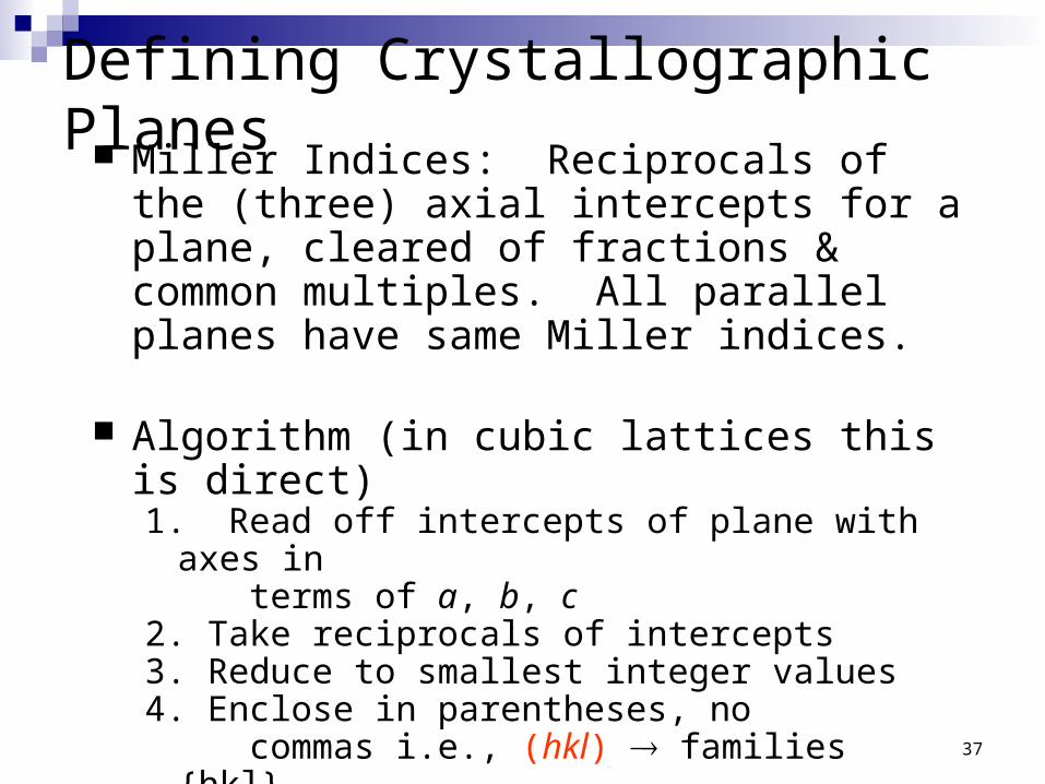
Defining Crystallographic Planes Miller Indices: Reciprocals of the (three) axial
intercepts for a plane, cleared of fractions & common multiples. All parallel planes have same Miller indices.
Algorithm (in cubic lattices this is direct)1. Read off intercepts of plane with axes in terms of a, b, c2. Take reciprocals of intercepts3. Reduce to smallest integer values4. Enclose in parentheses, no commas i.e., (hkl) families {hkl}
37
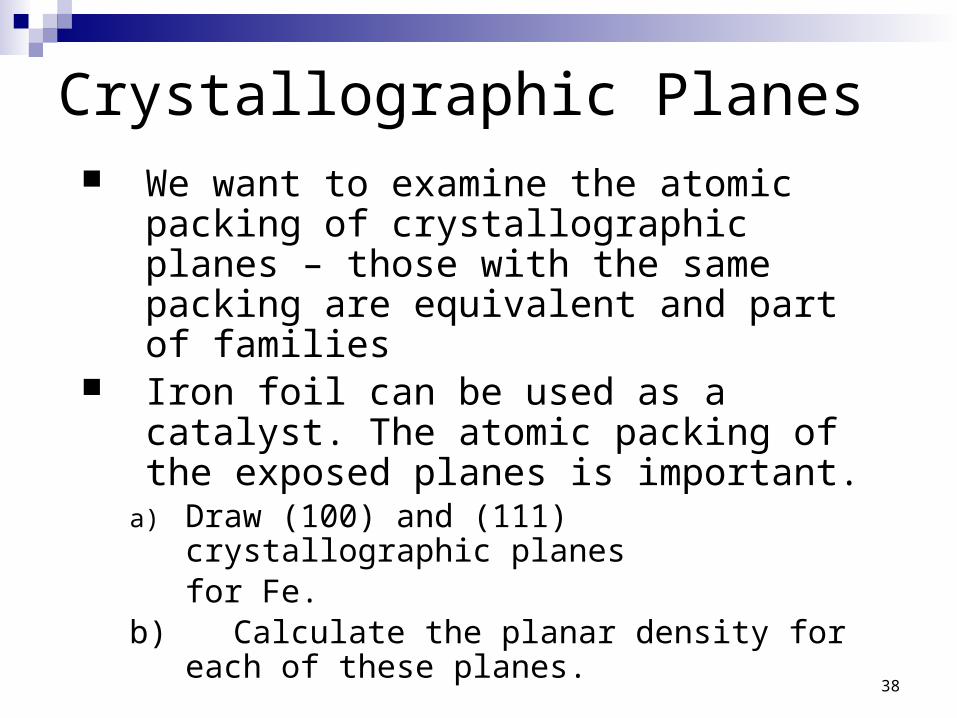
Crystallographic Planes We want to examine the atomic packing of
crystallographic planes – those with the same packing are equivalent and part of families
Iron foil can be used as a catalyst. The atomic packing of the exposed planes is important.
a) Draw (100) and (111) crystallographic planes for Fe.
b) Calculate the planar density for each of these planes.
38

Planar Density of (100) IronSolution: At T < 912C iron has the BCC structure.
(100)
Radius of iron R = 0.1241 nm
R3
34a=
2D repeat unit
= Planar Density = a2
1
atoms
2D repeat unit
= nm2
atoms12.1
m2
atoms= 1.2 x 10¹⁹
12
R3
34area
2D repeat unitAtoms: wholly contained and centered in/on plane within U.C., area of plane in U.C.39
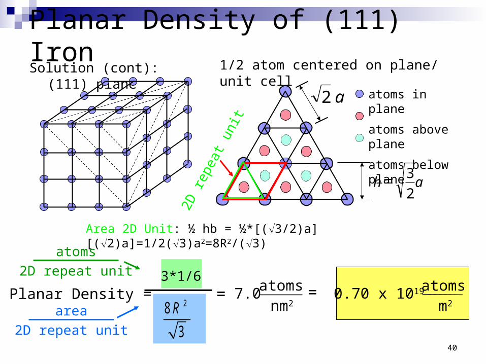
Planar Density of (111) IronSolution (cont): (111) plane 1/2 atom centered on plane/ unit cell
atoms in plane
atoms above plane
atoms below plane
ah2
3=
a 2
2D re
peat
uni
t
3*1/6= =
nm2
atoms7.0m2
atoms0.70 x 1019Planar Density =
atoms
2D repeat unit
area
2D repeat unit
28
3
R
Area 2D Unit: ½ hb = ½*[(3/2)a][(2)a]=1/2(3)a2=8R2/(3)
40