cs 152 computer architecture and engineering lecture …cs152/sp05/lecnotes/lec3-2.pdf · computer...
TRANSCRIPT

UC Regents Spring 2005 © UCBCS 152 L6: Teamwork
2005-2-3John Lazzaro
(www.cs.berkeley.edu/~lazzaro)
CS 152 Computer Architecture and Engineering
Lecture 6 – Teamwork
www-inst.eecs.berkeley.edu/~cs152/
TAs: Ted Hong and David Marquardt

UC Regents Spring 2005 © UCBCS 152 L6: Teamwork
Last Time: Timing and Xilinx
Spartan-3 FPGA Family: Introduction and Ordering Information
2 www.xilinx.com DS099-1 (v1.3) July 13, 20041-800-255-7778 Preliminary Product Specification
6
R
Architectural OverviewThe Spartan-3 family architecture consists of five funda-mental programmable functional elements:• Configurable Logic Blocks (CLBs) contain RAM-based
Look-Up Tables (LUTs) to implement logic and storageelements that can be used as flip-flops or latches.CLBs can be programmed to perform a wide variety oflogical functions as well as to store data.
• Input/Output Blocks (IOBs) control the flow of databetween the I/O pins and the internal logic of thedevice. Each IOB supports bidirectional data flow plus3-state operation. Twenty-four different signalstandards, including seven high-performancedifferential standards, are available as shown inTable 2. Double Data-Rate (DDR) registers areincluded. The Digitally Controlled Impedance (DCI)feature provides automatic on-chip terminations,simplifying board designs.
• Block RAM provides data storage in the form of 18-Kbitdual-port blocks.
• Multiplier blocks accept two 18-bit binary numbers asinputs and calculate the product.
• Digital Clock Manager (DCM) blocks provideself-calibrating, fully digital solutions for distributing,delaying, multiplying, dividing, and phase shifting clocksignals.
These elements are organized as shown in Figure 1. A ringof IOBs surrounds a regular array of CLBs. The XC3S50has a single column of block RAM embedded in the array.Those devices ranging from the XC3S200 to the XC3S2000have two columns of block RAM. The XC3S4000 andXC3S5000 devices have four RAM columns. Each columnis made up of several 18K-bit RAM blocks; each block isassociated with a dedicated multiplier. The DCMs are posi-tioned at the ends of the outer block RAM columns. The Spartan-3 family features a rich network of traces andswitches that interconnect all five functional elements,transmitting signals among them. Each functional elementhas an associated switch matrix that permits multiple con-nections to the routing.
Figure 1: Spartan-3 Family Architecture
DS099-1_01_032703
Notes: 1. The two additional block RAM columns of the XC3S4000 and XC3S5000
devices are shown with dashed lines. The XC3S50 has only the block RAM column on the far left.
wires
From: Xilinx Spartan 3 data sheet, simplified.

UC Regents Spring 2005 © UCBCS 152 L6: Teamwork
Spartan-3 FPGA Family: Introduction and Ordering Information
2 www.xilinx.com DS099-1 (v1.3) July 13, 20041-800-255-7778 Preliminary Product Specification
6
R
Architectural Overview
The Spartan-3 family architecture consists of five funda-mental programmable functional elements:• Configurable Logic Blocks (CLBs) contain RAM-based
Look-Up Tables (LUTs) to implement logic and storageelements that can be used as flip-flops or latches.CLBs can be programmed to perform a wide variety oflogical functions as well as to store data.
• Input/Output Blocks (IOBs) control the flow of databetween the I/O pins and the internal logic of thedevice. Each IOB supports bidirectional data flow plus3-state operation. Twenty-four different signalstandards, including seven high-performancedifferential standards, are available as shown inTable 2. Double Data-Rate (DDR) registers areincluded. The Digitally Controlled Impedance (DCI)feature provides automatic on-chip terminations,simplifying board designs.
• Block RAM provides data storage in the form of 18-Kbitdual-port blocks.
• Multiplier blocks accept two 18-bit binary numbers asinputs and calculate the product.
• Digital Clock Manager (DCM) blocks provideself-calibrating, fully digital solutions for distributing,delaying, multiplying, dividing, and phase shifting clocksignals.
These elements are organized as shown in Figure 1. A ringof IOBs surrounds a regular array of CLBs. The XC3S50has a single column of block RAM embedded in the array.Those devices ranging from the XC3S200 to the XC3S2000have two columns of block RAM. The XC3S4000 andXC3S5000 devices have four RAM columns. Each columnis made up of several 18K-bit RAM blocks; each block isassociated with a dedicated multiplier. The DCMs are posi-tioned at the ends of the outer block RAM columns. The Spartan-3 family features a rich network of traces andswitches that interconnect all five functional elements,transmitting signals among them. Each functional elementhas an associated switch matrix that permits multiple con-nections to the routing.
Figure 1: Spartan-3 Family Architecture
DS099-1_01_032703
Notes:
1. The two additional block RAM columns of the XC3S4000 and XC3S5000 devices are shown with dashed lines. The XC3S50 has only the block RAM column on the far left.
Recap: Why Xilinx wires are so slow ...Wires are slow because (1) each green dot is a transistor switch (2) path may not be shortest length (3) all wires are too long!
The best Xilinx users “write Verilog to the grid”. When Xilinx designs FPGA chips, wiring channels are optimized for (2) & (3).
Connect this
To this

UC Regents Spring 2005 © UCBCS 152 L6: Teamwork
Reminder: What are the green dots?
!"#$%&'())*++,!-.)'/012)*/345647&1'--
!"#$%&$'($)**)+,-,./
01).23#"%)$#%4"#5%.'6
78%*)9#%'$%+$#)9%2$'"":;',<.%
2'<<#2.,'<"%,<%.3#%,<.#$2'<<#2.
=8%5#>,<#%.3#%>4<2.,'<%'>%.3#%-'(,2%
+-'29"
?8%"#.%4"#$%';.,'<"6
89$:;$%':;1'<=&$2'><=2?@
8$%':;1'$%"A:B=A:"A:'><=2?@
8&<=>7<'#1@1:B2<=2?
0@A'<>,(4$).,'<%+,.%".$#)*B%2)<%
+#%-')5#5%4<5#$%4"#$%2'<.$'-6
CD--%-).23#"%)$#%".$4<(%.'(#.3#$%
,<%)%"3,>.%23),<6
01).23:+)"#5%EF,-,<GH%D-.#$)H%IJ
K$#2'<>,(4$)+-#
CL'-).,-#
C$#-).,L#-/%-)$(#8
-).23FFA “cross-point connection”
!"#$%&'())* ++,!-.)'/ 012)*/3456 47&1'-)
!"#$%&'()'*)+,-
. !'/)0)1-%+2%!"#$3-%4)221(%),5
6 789-):'0%/1',-%+2%)/701/1,*),;%
<-1(%7(+;('//'=)0)*9>
6 '((',;1/1,*%+2%),*1(:+,,1:*)+,%
?)(1->%',4
6 *81%='-):%2<,:*)+,'0)*9%+2%*81%
0+;):%=0+:@-A
. B+-*%-);,)2):',*%4)221(1,:1%)-%),%
*81%/1*8+4%2+(%7(+C)4),;%201D)=01%
=0+:@-%',4%:+,,1:*)+,-5%
. $,*)E2<-1%='-14%F1D5%$:*10G
H I+,EC+0'*)01>%(10'*)C109%-/'00
6 2)D14%F,+,E(17(+;('//'=01G
Set during configuration.
One flip-flop and a pass gate for each switch point. In order to have enough wires in the channels to wire up CLBs for most circuits, we need a lot of switch points! Thus, “80%+ of FPGA is for wiring”.


UC Regents Spring 2005 © UCBCS 152 L6: Teamwork
Spartan-3 FPGA Family: Introduction and Ordering Information
2 www.xilinx.com DS099-1 (v1.3) July 13, 20041-800-255-7778 Preliminary Product Specification
6
R
Architectural Overview
The Spartan-3 family architecture consists of five funda-mental programmable functional elements:• Configurable Logic Blocks (CLBs) contain RAM-based
Look-Up Tables (LUTs) to implement logic and storageelements that can be used as flip-flops or latches.CLBs can be programmed to perform a wide variety oflogical functions as well as to store data.
• Input/Output Blocks (IOBs) control the flow of databetween the I/O pins and the internal logic of thedevice. Each IOB supports bidirectional data flow plus3-state operation. Twenty-four different signalstandards, including seven high-performancedifferential standards, are available as shown inTable 2. Double Data-Rate (DDR) registers areincluded. The Digitally Controlled Impedance (DCI)feature provides automatic on-chip terminations,simplifying board designs.
• Block RAM provides data storage in the form of 18-Kbitdual-port blocks.
• Multiplier blocks accept two 18-bit binary numbers asinputs and calculate the product.
• Digital Clock Manager (DCM) blocks provideself-calibrating, fully digital solutions for distributing,delaying, multiplying, dividing, and phase shifting clocksignals.
These elements are organized as shown in Figure 1. A ringof IOBs surrounds a regular array of CLBs. The XC3S50has a single column of block RAM embedded in the array.Those devices ranging from the XC3S200 to the XC3S2000have two columns of block RAM. The XC3S4000 andXC3S5000 devices have four RAM columns. Each columnis made up of several 18K-bit RAM blocks; each block isassociated with a dedicated multiplier. The DCMs are posi-tioned at the ends of the outer block RAM columns. The Spartan-3 family features a rich network of traces andswitches that interconnect all five functional elements,transmitting signals among them. Each functional elementhas an associated switch matrix that permits multiple con-nections to the routing.
Figure 1: Spartan-3 Family Architecture
DS099-1_01_032703
Notes:
1. The two additional block RAM columns of the XC3S4000 and XC3S5000 devices are shown with dashed lines. The XC3S50 has only the block RAM column on the far left.
Question: You are Xilinx ...What are your tradeoffs for “wire design” when
you design a new part?
Connect this
To this
Many startups looking at this question ...

UC Regents Spring 2005 © UCBCS 152 L6: Teamwork
The lessons learned from the Fall 04 CS 152 class.
Today: Teamwork
In their own words: The final project presentation from a group whose final project did not make it to board.
Design Notebook: How to keep a design notebook for your team.

UC Regents Spring 2005 © UCBCS 152 L6: Teamwork
2004-12-13 Dave Patterson, John Lazzaro
Doug Densmore, Ted Hong, Brandon Ooi
CS 152 Computer Architecture and Engineering
What Went Right, What Went Wrong
www-inst.eecs.berkeley.edu/~cs152/
End-of-term presentation to CS hardware faculty ...

UC Regents Spring 2005 © UCBCS 152 L6: Teamwork
152 F04: Executive Summary
Successful Start: Lab 2 (Single Cycle Processor) and Lab 3 (Pipelines) went well. Most groups finished on time.
Stressful End: Lab 4 (Caches): 1 groupon time, 3 (?) were late, 1 never worked. Lab 5 (Final Project): 1 perfect project, 1 near miss, 2 worked in simulation.
What did we do after Lab 4? We held a “town meeting” in class ...

UC Regents Spring 2005 © UCBCS 152 L6: Teamwork
Lab 4 “Town Meeting”
Held during one of the last Fall 04 classes ...

UC Regents Spring 2005 © UCBCS 152 L6: Teamwork
Everyone worked hard. Only inretrospect did most students realize they also had to work smart.
Solution: Actually use the Lab Notebook to document processes.An example of working smart.
Example: Only one group member knows how to download to board. Once this member falls asleep, thegroup can’t go on working ...
Lab 4: Reflections from the TAs

UC Regents Spring 2005 © UCBCS 152 L6: Teamwork
A Better Way: Carry notebooks (silicon or paper) to meetings, andforce documentation of the decisions on details.
Example: Group has a long design meeting at start of project. Little is documented about signal names, state machine semantics. Members design incompatible modules, suffer.
Lab 4: Reflections from the TAs

UC Regents Spring 2005 © UCBCS 152 L6: Teamwork
A Better Way: One group spent 10 hours up front writing a cache test module. Brandon “The best cache testing I’ve ever seen”. They finished on time. An example of working smart.
Example: Comprehensive test rigsseen as a “checkoff item” for Lab report, done last. Actual debuggingproceeds in haphazard, painful way.
Lab 4: Reflections from the TAs
UC Regents Spring 2005 © UCBCS 152 L6: Teamwork
Design Notebook

UC Regents Spring 2005 © UCBCS 152 L6: Teamwork
Why should you keep a design notebook?° Keep track of the design decisions and the reasons
behind them• Otherwise, it will be hard to debug and/or refine
the design• Write it down so that can remember in long
project: 2 weeks ->2 yrs• Others can review notebook to see what
happened
° Record insights you have on certain aspect of the design as they come up
° Record of the different design & debug experiments• Memory can fail when very tired
° Industry practice: learn from others mistakes

UC Regents Spring 2005 © UCBCS 152 L6: Teamwork
Why do we keep it on-line?° You need to force yourself to take notes
• Open a window and leave an editor running:1) Acts as reminder to take notes2) Makes it easy to take notes
• 1) + 2) => will actually do it
° Take advantage of the window system’s “cut and paste” features
° It is much easier to read typing than writing° Also, paper log books have problems
• Limited capacity => end up with many books• May not have right book with you.• Can use computer to search files.

UC Regents Spring 2005 © UCBCS 152 L6: Teamwork
How to do it? See “Resources” web page° Keep it simple
• DON’T make it too elaborate (fonts, layout, ...)
° Separate the entries by dates• type “date” command in another window and cut&paste
° Start day with problems going to work on today
° Record output of simulation into log with cut&paste; add date• May help sort out which version of simulation did what
° Record key email with cut&paste
° Record of what works & doesn’t helps team decide what went wrong after you left
° Index: write a one-line summary of what you did at end of each day

UC Regents Spring 2005 © UCBCS 152 L6: Teamwork
1st page of Notebook (Index + Wed. 9/6/95)* Index ==============================================================
Wed Sep 6 00:47:28 PDT 1995 - Created the 32-bit comparator componentThu Sep 7 14:02:21 PDT 1995 - Tested the comparatorMon Sep 11 12:01:45 PDT 1995 - Investigated bug found by Bart in comp32 and fixed it+ ====================================================================Wed Sep 6 00:47:28 PDT 1995
Goal: Layout the schematic for a 32-bit comparator
I've layed out the schemtatics and made a symbol for the comparator. I named it comp32. The files are ~/wv/proj1/sch/comp32.sch ~/wv/proj1/sch/comp32.sym
Wed Sep 6 02:29:22 PDT 1995- ====================================================================
• Add 1 line index at front of log file at end of each session: date+summary• Start with date, time of day + goal• Make comments during day, summary of work• End with date, time of day (and add 1 line summary at front of file)

UC Regents Spring 2005 © UCBCS 152 L6: Teamwork
2nd page of Notebook (Thursday 9/7/95)
+ ====================================================================Thu Sep 7 14:02:21 PDT 1995
Goal: Test the comparator component
I've written a command file to test comp32. I've placed it in ~/wv/proj1/diagnostics/comp32.cmd.
I ran the command file in viewsim and it looks like the comparator is working fine. I saved the output into a log file called ~/wv/proj1/diagnostics/comp32.log
Notified the rest of the group that the comparator is done.
Thu Sep 7 16:15:32 PDT 1995- ====================================================================

UC Regents Spring 2005 © UCBCS 152 L6: Teamwork
3rd page of Notebook (Monday 9/11/95)+ ====================================================================Mon Sep 11 12:01:45 PDT 1995
Goal: Investigate bug discovered in comp32 and hopefully fix it
Bart found a bug in my comparator component. He left the following e-mail.
-------------------From [email protected] Sun Sep 10 01:47:02 1995Received: by wayne.manor (NX5.67e/NX3.0S) id AA00334; Sun, 10 Sep 95 01:47:01 -0800Date: Wed, 10 Sep 95 01:47:01 -0800From: Bart Simpson <[email protected]>To: [email protected], old_man@gokuraku, hojo@sanctuarySubject: [cs152] bug in comp32Status: R
Hey Bruce,I think there's a bug in your comparator. The comparator seems to think that ffffffff and fffffff7 are equal.
Can you take a look at this?Bart----------------

UC Regents Spring 2005 © UCBCS 152 L6: Teamwork
4th page of Notebook (9/11/95 contd)I verified the bug. here's a viewsim of the bug as it appeared.. (equal should be 0 instead of 1)------------------SIM>stepsize 10nsSIM>v a_in A[31:0]SIM>v b_in B[31:0]SIM>w a_in b_in equalSIM>a a_in ffffffff\hSIM>a b_in fffffff7\hSIM>simtime = 10.0ns A_IN=FFFFFFFF\H B_IN=FFFFFFF7\H EQUAL=1 Simulation stopped at 10.0ns.-------------------
Ah. I've discovered the bug. I mislabeled the 4th net in the comp32 schematic.
I corrected the mistake and re-checked all the other labels, just in case.
I re-ran the old diagnostic test file and tested it against the bug Bart found. It seems to be working fine. hopefully there aren’t any more bugs:)

UC Regents Spring 2005 © UCBCS 152 L6: Teamwork
5th page of Notebook (9/11/95 continued) On second inspectation of the whole layout, I think I can remove one level of gates in the design and make it go faster. But who cares! the comparator is not in the critical path right now. the delay through the ALU is dominating the critical path. so unless the ALU gets a lot faster, we can live with a less than optimal comparator.
I e-mailed the group that the bug has been fixed
Mon Sep 11 14:03:41 PDT 1995- ====================================================================
• Perhaps later critical path changes; what was idea to make comparator faster? Check log book!

UC Regents Spring 2005 © UCBCS 152 L6: Teamwork
Administrivia: Upcoming deadlines ...
Friday 2/4: “ModelSim Checkoff”, 12-1, 119 Cory. For 61(c) students, 150 Lab Lecture 3”, 1-2 PM, 125 Cory.
Monday 2/14: Lab 2 final report due via the submit program, 11:59 PM.
Friday 2/11: “Xilinx Checkoff”, 12-1, 119 Cory. For 61(c) students, 150 Lab Lecture 4”, 1-2 PM, 125 Cory.

UC Regents Spring 2005 © UCBCS 152 L6: Teamwork
Back to Fall 04 ...

UC Regents Spring 2005 © UCBCS 152 L6: Teamwork
152 F04: Executive Summary
Successful Start: Lab 2 (Single Cycle Processor) and Lab 3 (Pipelines) went well. Most groups finished on time.
Stressful End: Lab 4 (Caches): 1 groupon time, 3 (?) were late, 1 never worked. Lab 5 (Final Project): 1 perfect project, 1 near miss, 2 worked in simulation.
Let’s take a look at the final project presentation of a “worked in simulation, not on the board” group.

UC Regents Spring 2005 © UCBCS 152 L6: Teamwork
Other Teamwork Topics

UC Regents Spring 2005 © UCBCS 152 L6: Teamwork
Lesson: Most CAD has bugs, and we can’t know them all. Be paranoid --never blindly trust any CAD tool !
Example: We recommended using the CoreGen multiplier generators to Fall 04. The tool was buggy (my bad).The most successful groups realized this early and switched methods.
CAD: Never blindly trust a CAD tool

UC Regents Spring 2005 © UCBCS 152 L6: Teamwork
Backups: Use CVS, but also make safety copies off-site regularly (gmail).New CVS users often lose work as they are learning how to use CVS. Beware of CVS NT permissions issues.
Verilog: Carefully written Verilog will yield identical semantics in ModelSim and Synplicity. If you write your code in this way, many “works in Modelsim but not on Xilinx” issues disappear.
CAD: Technical issues ...
Always check log files, and inspect output tools produce!

UC Regents Spring 2005 © UCBCS 152 L6: Teamwork
Schematics: This schematic uses wires ...
1600 IEEE JOURNAL OF SOLID-STATE CIRCUITS, VOL. 36, NO. 11, NOVEMBER 2001
Fig. 1. Process SEM cross section.
The process was raised from [1] to limit standby power.
Circuit design and architectural pipelining ensure low voltage
performance and functionality. To further limit standby current
in handheld ASSPs, a longer poly target takes advantage of the
versus dependence and source-to-body bias is used
to electrically limit transistor in standby mode. All core
nMOS and pMOS transistors utilize separate source and bulk
connections to support this. The process includes cobalt disili-
cide gates and diffusions. Low source and drain capacitance, as
well as 3-nm gate-oxide thickness, allow high performance and
low-voltage operation.
III. ARCHITECTURE
The microprocessor contains 32-kB instruction and data
caches as well as an eight-entry coalescing writeback buffer.
The instruction and data cache fill buffers have two and four
entries, respectively. The data cache supports hit-under-miss
operation and lines may be locked to allow SRAM-like oper-
ation. Thirty-two-entry fully associative translation lookaside
buffers (TLBs) that support multiple page sizes are provided
for both caches. TLB entries may also be locked. A 128-entry
branch target buffer improves branch performance a pipeline
deeper than earlier high-performance ARM designs [2], [3].
A. Pipeline Organization
To obtain high performance, the microprocessor core utilizes
a simple scalar pipeline and a high-frequency clock. In addition
to avoiding the potential power waste of a superscalar approach,
functional design and validation complexity is decreased at the
expense of circuit design effort. To avoid circuit design issues,
the pipeline partitioning balances the workload and ensures that
no one pipeline stage is tight. The main integer pipeline is seven
stages, memory operations follow an eight-stage pipeline, and
when operating in thumb mode an extra pipe stage is inserted
after the last fetch stage to convert thumb instructions into ARM
instructions. Since thumb mode instructions [11] are 16 b, two
instructions are fetched in parallel while executing thumb in-
structions. A simplified diagram of the processor pipeline is
Fig. 2. Microprocessor pipeline organization.
shown in Fig. 2, where the state boundaries are indicated by
gray. Features that allow the microarchitecture to achieve high
speed are as follows.
The shifter and ALU reside in separate stages. The ARM in-
struction set allows a shift followed by an ALU operation in a
single instruction. Previous implementations limited frequency
by having the shift and ALU in a single stage. Splitting this op-
eration reduces the critical ALU bypass path by approximately
1/3. The extra pipeline hazard introduced when an instruction is
immediately followed by one requiring that the result be shifted
is infrequent.
Decoupled Instruction Fetch.A two-instruction deep queue is
implemented between the second fetch and instruction decode
pipe stages. This allows stalls generated later in the pipe to be
deferred by one or more cycles in the earlier pipe stages, thereby
allowing instruction fetches to proceed when the pipe is stalled,
and also relieves stall speed paths in the instruction fetch and
branch prediction units.
Deferred register dependency stalls. While register depen-
dencies are checked in the RF stage, stalls due to these hazards
are deferred until the X1 stage. All the necessary operands are
then captured from result-forwarding busses as the results are
returned to the register file.
One of the major goals of the design was to minimize the en-
ergy consumed to complete a given task. Conventional wisdom
has been that shorter pipelines are more efficient due to re-

UC Regents Spring 2005 © UCBCS 152 L6: Teamwork
This schematic uses labels ...1600 IEEE JOURNAL OF SOLID-STATE CIRCUITS, VOL. 36, NO. 11, NOVEMBER 2001
Fig. 1. Process SEM cross section.
The process was raised from [1] to limit standby power.
Circuit design and architectural pipelining ensure low voltage
performance and functionality. To further limit standby current
in handheld ASSPs, a longer poly target takes advantage of the
versus dependence and source-to-body bias is used
to electrically limit transistor in standby mode. All core
nMOS and pMOS transistors utilize separate source and bulk
connections to support this. The process includes cobalt disili-
cide gates and diffusions. Low source and drain capacitance, as
well as 3-nm gate-oxide thickness, allow high performance and
low-voltage operation.
III. ARCHITECTURE
The microprocessor contains 32-kB instruction and data
caches as well as an eight-entry coalescing writeback buffer.
The instruction and data cache fill buffers have two and four
entries, respectively. The data cache supports hit-under-miss
operation and lines may be locked to allow SRAM-like oper-
ation. Thirty-two-entry fully associative translation lookaside
buffers (TLBs) that support multiple page sizes are provided
for both caches. TLB entries may also be locked. A 128-entry
branch target buffer improves branch performance a pipeline
deeper than earlier high-performance ARM designs [2], [3].
A. Pipeline Organization
To obtain high performance, the microprocessor core utilizes
a simple scalar pipeline and a high-frequency clock. In addition
to avoiding the potential power waste of a superscalar approach,
functional design and validation complexity is decreased at the
expense of circuit design effort. To avoid circuit design issues,
the pipeline partitioning balances the workload and ensures that
no one pipeline stage is tight. The main integer pipeline is seven
stages, memory operations follow an eight-stage pipeline, and
when operating in thumb mode an extra pipe stage is inserted
after the last fetch stage to convert thumb instructions into ARM
instructions. Since thumb mode instructions [11] are 16 b, two
instructions are fetched in parallel while executing thumb in-
structions. A simplified diagram of the processor pipeline is
Fig. 2. Microprocessor pipeline organization.
shown in Fig. 2, where the state boundaries are indicated by
gray. Features that allow the microarchitecture to achieve high
speed are as follows.
The shifter and ALU reside in separate stages. The ARM in-
struction set allows a shift followed by an ALU operation in a
single instruction. Previous implementations limited frequency
by having the shift and ALU in a single stage. Splitting this op-
eration reduces the critical ALU bypass path by approximately
1/3. The extra pipeline hazard introduced when an instruction is
immediately followed by one requiring that the result be shifted
is infrequent.
Decoupled Instruction Fetch.A two-instruction deep queue is
implemented between the second fetch and instruction decode
pipe stages. This allows stalls generated later in the pipe to be
deferred by one or more cycles in the earlier pipe stages, thereby
allowing instruction fetches to proceed when the pipe is stalled,
and also relieves stall speed paths in the instruction fetch and
branch prediction units.
Deferred register dependency stalls. While register depen-
dencies are checked in the RF stage, stalls due to these hazards
are deferred until the X1 stage. All the necessary operands are
then captured from result-forwarding busses as the results are
returned to the register file.
One of the major goals of the design was to minimize the en-
ergy consumed to complete a given task. Conventional wisdom
has been that shorter pipelines are more efficient due to re-
p1
p1
p2
p2
p3
p3
p2
p4
p4
Which is easier to understand?
UC Regents Spring 2005 © UCBCS 152 L6: Teamwork
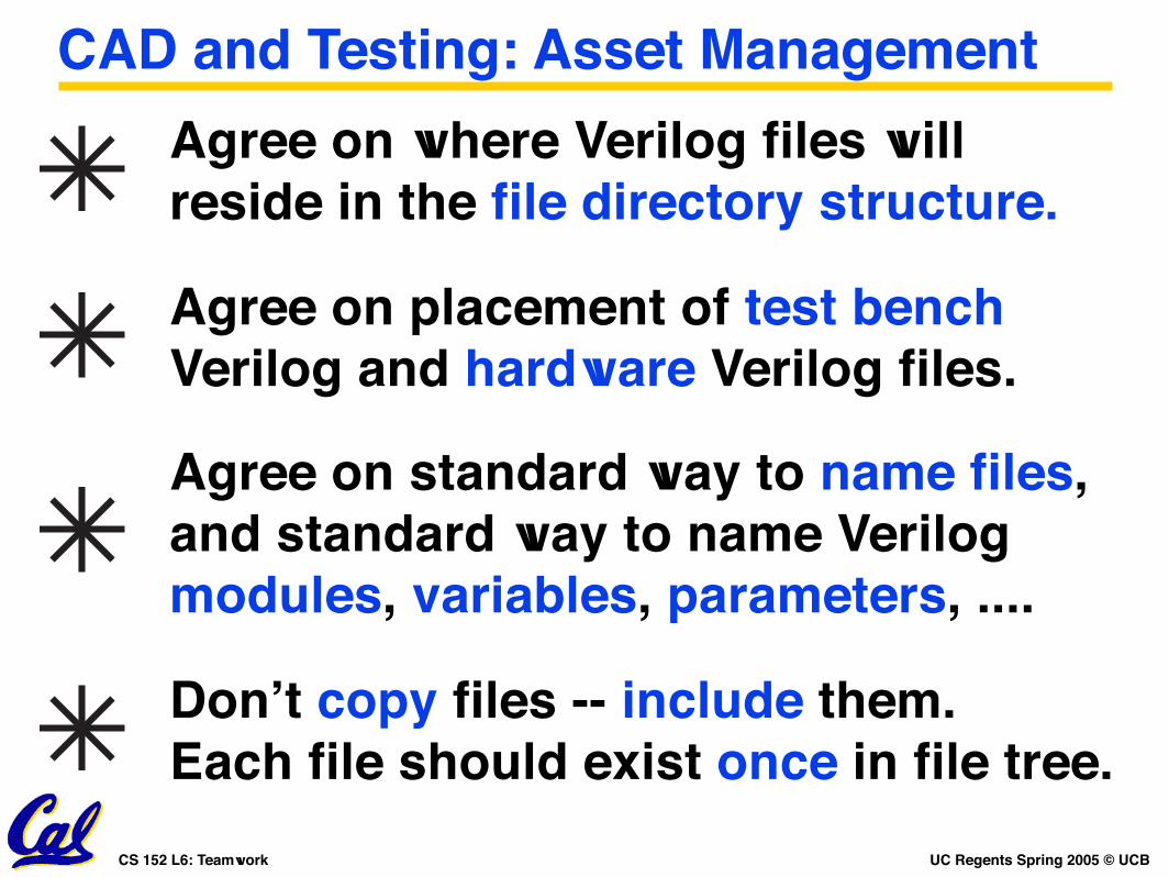
Agree on where Verilog files will reside in the file directory structure.
CAD and Testing: Asset Management
Agree on placement of test benchVerilog and hardware Verilog files.
Agree on standard way to name files,and standard way to name Verilog modules, variables, parameters, ....
Don’t copy files -- include them. Each file should exist once in file tree.

UC Regents Spring 2005 © UCBCS 152 L6: Teamwork
Solution #2: Consensus. Keeping in mind the goal (correctly working CPU on the board on schedule), what option brings the group closer to the goal?
Example: 3 members want to do the design one way; member number 4 does not agree.
Group Dynamics: How to Disagree
Solution #1: Voting. “Fair”. But, what if the “loser” was technically correct?
Never lose sight of the goal !

UC Regents Spring 2005 © UCBCS 152 L6: Teamwork
It is certainly of more consequence to a man, that he has learnt to govern his passions in spite of temptation, to be just in his dealings, to be temperate in his pleasures, to support himself with fortitude under his misfortunes, to behave with prudence in all his affairs and every circumstance of life; I say, it is of much more real advantage to him to be thus qualified, than to be a master of all the arts and sciences in the world beside. Virtue alone is sufficient to make a man great, glorious, and happy. -- Ben Franklin
Group Dynamics: Humility is important!
More at: http://www.cs.berkeley.edu/~dsw/Thanks to Daniel S. Wilkerson

UC Regents Spring 2005 © UCBCS 152 L6: Teamwork
Where we are now, and what is next
Pipelining begins ...
Software for teamwork, group dynamics, etc ...