cs1 series single phase solid state relays - chromalox · high voltage is used in the operation of...
TRANSCRIPT

1
Installation Instructions
CS1 Series Single Phase Solid State Relays
PK5210037-75549
June 2015

2
Important Safeguards
HIGH VOLTAGE is used in the operation of this equipment; DEATH ON CONTACT may result if personnel fail to observe safety precautions.
Learn the areas containing high-voltage con-nections when installing or operating this equipment.
Be careful not to contact high-voltage connec-tions when installing or operating this equip-ment.
Before working inside the equipment, turn power off and ground all points of high poten-tial before touching them.
ELECTRIC SHOCK HAZARD: Any installation in-volving control equipment must be performed by a qualified person and must be effective-ly grounded in accordance with the National Electrical Code to eliminate shock hazard.

3
CS1 - Single Phase Solid State Relay Power Controller
GeneralThe CS1 Series of solid state relays are an ideal, low cost power control solution for switching resistive loads found applications in such as furnaces, ovens, heat treating, injection molding, thermoforming, press platens, commercial food equipment, semiconductor, lighting and drying, just to name a few.
The CS1 Series power controllers feature: • Rugged, industrial design & touch-safe exterior• Conservative, continuous service ratings at 40˚C • Up to 120 Amps and up to 600 VAC• AC and DC Voltage command signals • Zero cross firing• Integrated heat sink• SCR thermal protection with LED indication• Optional over temperature alarm• Optional load / line interrupt alarm• Latching Alarm (DC gated versions only)• USA & Canadian UL component recognition• CE conformity
The owner/installer must provide all necessary safety and protection devices and follow all current electrical wiring standards and regula-tions. Failure to do so may compromise the in-tegrity of the controller and / or cause product failure resulting in a safety risk to operational and service personnel.
This controller utilizes a heat sink which is de-signed to cool the unit during operation. Un-der no circumstance should air flow around the controller be compromised in any way. Failure to do so may result in the overheating of the controller, product failure, product tempera-tures and even fire.
During continuous operation, the heat sink can reach very high temperatures, and keeps a high temperature even after the unit is turned off due to its high thermal inertia.
Higher voltages may be present. DO NOT work on the power section without first cutting out electrical power to the panel. Failure to do so may cause serious injury or death.
To ensure proper performance, maximum safety and reliability, it is essential to install the unit correctly. This includes proper mounting, spacing, hardware and wir-ing. See below:
1. Maximum surrounding air temperature is 40°C in “Open Type Equipment” which is suitable for use in pollution degree 2.
2. Install the unit vertically (max 10° inclination from vertical axis).
Spacing:
- Minimum vertical distance between unit and panel wall: 3.94” (100 mm)
- Minimum horizontal distance between unit and panel wall: .79” (20 mm)
- Minimum vertical distance between adjacent power control units: 11.81” (300 mm)
- Minimum horizontal distance between adjacent power control units: .79” (20 mm)
Installation and Operation

4
Dimensions & Weights
Depth = 5.6” (142)Weight = 2.9 lb (1300 g) 3.7 lb (1700 g)
Depth = 4.2” (107) 5.6” (142) 5.6” (142) 5.6” (142)Weight = .71 lb (320 g) 1.2 lb (540 g) 1.9 lb (900 g) 2.6 lb (1200 g)
(without fan)(without fan)(with fan)
1.97
” (5
0) m
ax.
1.18
” (5
0)
5” (127)3.15” (80)2.36” (60)1.4” (35).95” (24)
3.94
” (1
00)
4.24
” (1
08)
0.5”
(14)
0.7”
(18)
CS1 25 A CS1 40 A CS1 50 A CS1 60 A
CS1 75 ACS1 90 ACS1 120 A
CS1 CS1 CS1 CS1 CS1
Control & Power Connection Points & Indication Logic
LED 1 Red: Input Control Signal Present
Yellow: Overtemperature Condition,Input Control Signal Present
Blank: No Input Control Signal
LED 2 (Optional)Red: Alarm Output ActiveBlank: No Alarm Output
LOAD2 /T1
LINE1 /L1
GROUND
1 2 3 4 5 6 7 8
+Control Signal Input –
24 VDC or 20 - 260 VAC/DC
25 & 40 Amp 50 -120 Amp
ON (Red) OVER TEMP (Yellow)
AL
OptionalExternal - 24 VDC Power Supply
External +24 VDC Power Supply
Alarm Output See Wiring
Alarm OutputDiagrams
2 3
ON
LOAD2 /T1
LINE 1 /L1
GROUND
+–
5
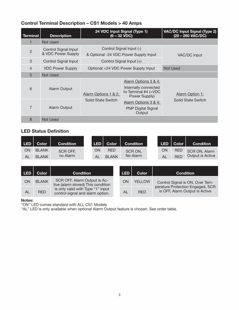
Control Terminal Description – CS1 Models > 40 Amps
Terminal Description24 VDC Input Signal (Type 1)
(6 – 32 VDC)VAC/DC Input Signal (Type 2)
(20 – 260 VAC/DC)
1 Not Used
2 Control Signal Input& VDC Power Supply
Control Signal Input (-)
& Optional -24 VDC Power Supply Input VAC/DC Input
3 Control Signal Input Control Signal Input (+)
4 VDC Power Supply Optional +24 VDC Power Supply Input Not Used
5 Not Used
6 Alarm OutputAlarm Options 1 & 2:
Solid State Switch
Alarm Options 3 & 4:
Internally connected to Terminal #4 (+VDC
Power Supply) Alarm Option 1:
Solid State Switch
7 Alarm OutputAlarm Options 3 & 4:
PNP Digital Signal Output
8 Not Used
LED Status Definition
LED Color Condition LED Color Condition LED Color Condition
ON BLANK SCR OFF, no Alarm
ON RED SCR ON,No Alarm
ON RED SCR ON, Alarm Output is ActiveAL BLANK AL BLANK AL RED
LED Color Condition LED Color Condition
ON BLANK SCR OFF, Alarm Output is Ac-tive (alarm stored) This condition is only valid with Type “1” input control signal and alarm option.
ON YELLOW Control Signal is ON, Over Tem-perature Protection Engaged, SCR
is OFF, Alarm Output is ActiveAL RED AL RED
Notes:“ON” LED comes standard with ALL CS1 Models“AL” LED is only available when optional Alarm Output feature is chosen. See order table.

6
Single Phase Load
CS1 with
20-260 VAC/DCControl Signal
Input
CS1 with6-32 VDC
Control SignalInput
Control Signal Output
Temperature / Process Controller
+ –
Phase
Neutral
Ground
FuseLoad
CS1 with 20- 260 VAC/DC Control Signal Input
CS1 with 6-32 VDC Control Signal Input
Control Signal Output
+ –
Temperature / Process Controller
Delta LoadWye or
Star Load
R R
R
R
R
RFuseFuse
Phase L1Phase L2Phase L3Ground
Controlling 2 Phases (Legs) of a Three Phase (no Neutral) Wye (Star) or Delta Load Configuration
7
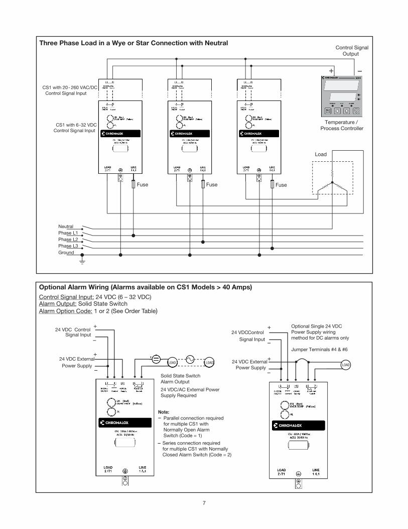
Three Phase Load in a Wye or Star Connection with Neutral
CS1 with 20- 260 VAC/DC Control Signal Input
CS1 with 6-32 VDC Control Signal Input
Control Signal Output
Temperature /
+
Neutral Phase L1 Phase L2 Phase L3 Ground
Fuse Fuse Fuse
Load
–
Fuse
Process Controller
+24 VDC Control
Signal Input
Solid State Switch Alarm Output
24 VDC/AC External PowerSupply Required
Note: Parallel connection required
for multiple CS1 withNormally Open AlarmSwitch (Code = 1)
Series connection requiredfor multiple CS1 with NormallyClosed Alarm Switch (Code = 2)
+24 VDC External Power Supply
LOAD LOAD
+24 VDC Control
Signal Input
+24 VDC External
Power Supply LOAD
Optional Single 24 VDCPower Supply wiringmethod for DC alarms only
Jumper Terminals #4 & #6
–
–
–
–
–
–
Optional Alarm Wiring (Alarms available on CS1 Models > 40 Amps)Control Signal Input: 24 VDC (6 – 32 VDC)Alarm Output: Solid State SwitchAlarm Option Code: 1 or 2 (See Order Table)
8
+24 VDC Control
Signal Input
Digital Logic +24 VDCPNP Output
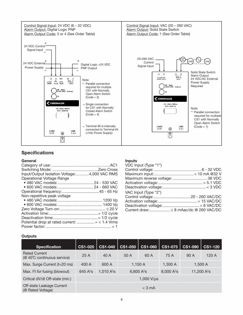
Note: Parallel connectionrequired for multipleCS1 with NormallyOpen Alarm Switch(Code = 3)
Single connectionfor CS1 with NormallyClosed Alarm Switch(Code = 4)
Terminal #6 is internallyconnected to Terminal #4(+Vdc Power Supply)
+ + 20-260 VACControl
Signal Input
Solid State Switch Alarm Output 24 VDC/AC ExternalPower SupplyRequired
Note: Parallel connectionrequired for multipleCS1 with NormallyOpen Alarm Switch(Code = 1)
24 VDC External Power Supply
LOAD
LOAD
–
– –
–
–
–
–
Control Signal Input: 24 VDC (6 – 32 VDC)Alarm Output: Digital Logic PNPAlarm Output Code: 3 or 4 (See Order Table)
Control Signal Input: VAC (20 – 260 VAC)Alarm Output: Solid State SwitchAlarm Output Code: 1 (See Order Table)
GeneralCategory of use: .....................................................AC1Switching Mode: .........................................Zero CrossInput/Output Isolation Voltage: ............4,000 VAC RMSOperational Voltage Range • 480 VAC models: ................................ 24 - 530 VAC • 600 VAC models: ................................ 24 - 660 VACOperational frequency: .................................45 - 65 HzNon-repetitive peak voltage • 480 VAC models: ........................................ 1200 Vp • 600 VAC models: ........................................ 1400 VpZero Voltage Turn-on: ......................................... ≤ 20 VActivation time: ............................................= 1/2 cycleDeactivation time: ........................................= 1/2 cyclePotential drop at rated current: ................ = < 1.4 VrmsPower factor: ........................................................... = 1
InputsVDC Input (Type “1”)Control voltage: ...........................................6 - 32 VDCMaximum input: ....................................< 10 mA @32 VMaximum reverse voltage: ............................... 36 VDCActivation voltage: ........................................ > 5.1 VDCDeactivation voltage: ....................................... < 3 VDCVAC Input (Type “2”)Control voltage: .................................20 - 260 VAC/DCActivation voltage: ................................... > 15 VAC/DCDeactivation voltage: ................................. < 6 VAC/DCCurrent draw: ...................≤ 8 mAac/dc @ 260 VAC/DC
Specifications
Outputs
Specification CS1-025 CS1-040 CS1-050 CS1-060 CS1-075 CS1-090 CS1-120
Rated Current(@ 40˚C continuous service) 25 A 40 A 50 A 60 A 75 A 90 A 120 A
Max. Surge Current (t=20 ms) 400 A 600 A 1,150 A 1,300 A 1,500 A
Max. I2t for fusing (blowout) 645 A2s 1,010 A2s 6,600 A2s 8,000 A2s 11,200 A2s
Critical dV/dt Off-state (min.) 1,000 V/μs
Off-state Leakage Current (@ Rated Voltage) < 3 mA
9
Environment ConditionsOperating Temperature Range: ...................0˚C to 80˚C Maximum Relative Humidity: .....................50% @ 40˚C Max. Installation Altitude: ........2000 m above sea levelPollution Level: ............................................................2Storage Temperature: ............................ -20˚C to +85˚C Junction Temperature: ......................................... 125˚C
This device conforms to European Union Directive 2004/108/CE and 2006/95/CE as amended with refer-ence to generic standards: EN 61000-6-2 (immunity in industrial environment) EN 61000-6-4 (emission in industrial environment) EN 61010-1 (safety regulations).
Alarm OutputsThe alarms are only available only on models rated at 50 Amps and greater. There are two types of alarm outputs:1. Solid State Switch – Controls a connected device
for an alarm event, such as a horn or light. a. Requires external 24 VAC/DC power supply b. Ratings: Imax = 150 mA Vmax = 30 VAC/DC Z close < 15 Ω (impedance) Z open > 1 MΩ (impedance)2. Digital Logic – PNP output signal for logic gated de-
vices, such as PLCs a. Requires external 24 VDC (6-32 VDC) power sup-
ply b. Ratings: Imax = 150 mA Vmax = 30 VAC/DC
Alarm BehaviorThe functionality of the alarm switching varies depend-ing on the type of gating signal
For Models with 24 VDC Input Control SignalThe alarm output function actuates (opens or closes) the isolated solid state output switch (or digital output sig-
nal) when it detects any of the following fault conditions: The control signal is active, but: • There is no current on the load (zero current or inter-
rupted load)• There is no line voltage power supply • The internal temperature limit of the SSR has been
exceeded
Latching Alarm Function On the VDC gated CS1 controllers, the alarm state re-mains latched if the Control Signal is switched off. The Alarm Output will reset (unlatch) once the current load is restored or when the CS1 24 VDC power supply is cycled.
For Models with 20 - 260 VAC/DC Input Control SignalThe alarm output function closes the isolated solid state output switch when it detects any of the following fault conditions:The control signal is active, but: • There is no current on the load (zero current or inter-
rupted load)• There is no line voltage power supply • The internal temperature limit of the SSR has been
exceeded
Latching Note:On the VAC gated CS1 controllers, in the absence of the control signal, the alarm output is always open. The alarm memory latch function is not possible as with the CS1 with VDC control signal.
Integrated Thermal ProtectionThe SSR temperature is constantly monitored. If the maximum temperature limit (230°F/110°C) is exceed-ed, current to the load is interrupted and the YELLOW over-temperature condition LED illuminates.
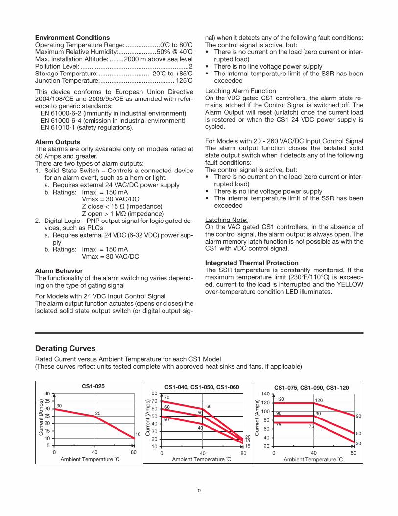
Derating CurvesRated Current versus Ambient Temperature for each CS1 Model(These curves reflect units tested complete with approved heat sinks and fans, if applicable)
30
25
10
5
101520
253035
40
0 40 80
Cur
rent
(Am
ps)
Ambient Temperature ˚C
CS1-025
50
40
15
6050
18
70
60
20
10
20
30
40
50
60
70
80
0 40 80
Cur
rent
(Am
ps)
Ambient Temperature ˚C
CS1-040, CS1-050, CS1-060
75 75
30
90 90
50
120 120
90
20
40
60
80
100
120
140
0 40 80
Cur
rent
(Am
ps)
Ambient Temperature ˚C
CS1-075, CS1-090, CS1-120
10
Limited Warranty:Please refer to the Chromalox limited warranty applicable to this product at
http://www.chromalox.com/customer-service/policies/termsofsale.aspx.
Chromalox, Inc.1347 Heil Quaker Boulevard
Lavergne, TN 37086(615) 793-3900
www.chromalox.com
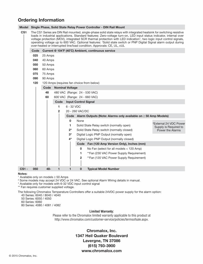
Model Single Phase, Solid State Relay Power Controller - DIN Rail Mount
CS1 The CS1 Series are DIN Rail mounted, single-phase solid state relays with integrated heatsink for switching resistive loads in industrial applications. Standard features: Zero-voltage turn-on, LED input status indicator, internal over voltage protection (MOV), integrated SCR thermal protection with LED indication1, two logic input control signals, operating voltage up to 600 VAC. Optional features: 1Solid state switch or PNP Digital Signal alarm output during over-heated or interrupted line/load condition. Approvals: CE, UL, cUL
Code Current @ 104˚F (40˚C) Ambient, continuous service
025 25 Amps
040 40 Amps
050 50 Amps
060 60 Amps
075 75 Amps
090 90 Amps
120 120 Amps (requires fan choice from below)
Code Nominal Voltage
48 480 VAC (Range: 24 - 530 VAC)
60 600 VAC (Range: 24 - 660 VAC)
Code Input Control Signal
1 6 - 32 VDC
2 20 - 260 VAC/DC
Code Alarm Outputs (Note: Alarms only available on ≥ 50 Amp Models)
0 None
1 Solid State Relay switch (normally open)
2* Solid State Relay switch (normally closed)
3* Digital Logic PNP Output (normally open)
4* Digital Logic PNP Output (normally closed)
Code Fan (120 Amp Version Only), Inches (mm)
0 No Fan (select for all models < 120 Amp)
1 **Fan (230 VAC Power Supply Requirement)
2 **Fan (120 VAC Power Supply Requirement)
CS1 - 050 48- 1 1 0 Typical Model Number
Notes:1 Available only on models ≥ 50 Amps2 Some models may accept 24 VDC or 24 VAC. See optional Alarm Wiring details in manual.* Available only for models with 6-32 VDC input control signal** Fan requires customer supplied voltage.
The following Chromalox Temperature Controllers offer a suitable 24VDC power supply for the alarm option: 40 Series: 6040 / 8040 / 4040 50 Series: 6050 / 4050 60 Series: 6060 80 Series: 4080 / 4081 / 4082
Ordering Information
2External 24 VDC Power Supply is Required to
Power the Alarms
© 2015 Chromalox, Inc.