cs152: computer systems architecture pipelining
TRANSCRIPT
CS152: Computer Systems ArchitecturePipelining
Sang-Woo Jun
Winter 2021
Large amount of material adapted from MIT 6.004, “Computation Structures”,Morgan Kaufmann “Computer Organization and Design: The Hardware/Software Interface: RISC-V Edition”,
and CS 152 Slides by Isaac Scherson

Eight great ideas
❑ Design for Moore’s Law
❑ Use abstraction to simplify design
❑ Make the common case fast
❑ Performance via parallelism
❑ Performance via pipelining
❑ Performance via prediction
❑ Hierarchy of memories
❑ Dependability via redundancy
But before we start…

Performance Measures
❑ Two metrics when designing a system
1. Latency: The delay from when an input enters the system until its associated output is produced
2. Throughput: The rate at which inputs or outputs are processed
❑ The metric to prioritize depends on the applicationo Embedded system for airbag deployment? Latency
o General-purpose processor? Throughput

Performance of Combinational Circuits
❑ For combinational logico latency = tPD
o throughput = 1/tPD
X Y
Is this an efficient way of using hardware?
X
F(X)
G(X)
H(X)
F and G not doing work!Just holding output data
Source: MIT 6.004 2019 L12

Pipelined Circuits
❑ Pipelining by adding registers to hold F and G’s outputo Now F & G can be working on input Xi+1 while H is performing computation on Xi
o A 2-stage pipeline!
o For input X during clock cycle j, corresponding output is emitted during clock j+2.
Y
Assuming latencies of 15, 20, 25…
F(X)
G(X)
H(X)
Assuming ideal registers
15
20
Source: MIT 6.004 2019 L12
25

Pipelined Circuits
20+25=45 25+25=50
Latency Throughput
Unpipelined 45 1/45
2-stage pipelined 50 1/25(Worse!) (Better!)
Source: MIT 6.004 2019 L12
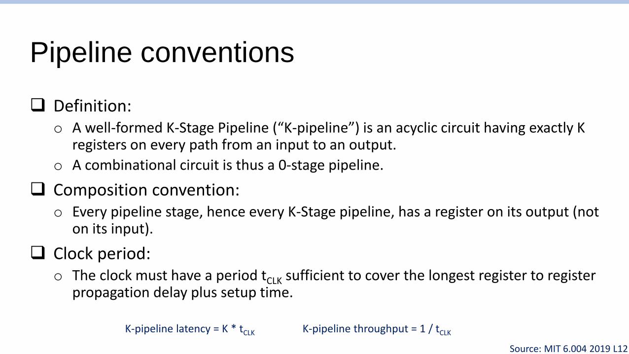
Pipeline conventions
❑ Definition:o A well-formed K-Stage Pipeline (“K-pipeline”) is an acyclic circuit having exactly K
registers on every path from an input to an output.
o A combinational circuit is thus a 0-stage pipeline.
❑ Composition convention:o Every pipeline stage, hence every K-Stage pipeline, has a register on its output (not
on its input).
❑ Clock period:o The clock must have a period tCLK sufficient to cover the longest register to register
propagation delay plus setup time.
K-pipeline latency = K * tCLK K-pipeline throughput = 1 / tCLK
Source: MIT 6.004 2019 L12

Ill-formed pipelines
❑ Is the following circuit a K-stage pipeline? No
❑ Problem:o Some paths have different number of registers
o Values from different input sets get mixed! -> Incorrect results• B(Yt-1,A(Xt)) <- Mixing values from t and t-1
A
B
CX
Y
2
2
1
Source: MIT 6.004 2019 L12

A pipelining methodology
❑ Step 1:o Draw a line that crosses every output in the
circuit, and mark the endpoints as terminal points.
❑ Step 2:o Continue to draw new lines between the terminal
points across various circuit connections, ensuring that every connection crosses each line in the same direction.
o These lines demarcate pipeline stages.
❑ Step 3:o Add a pipeline register at every point where a separating line crosses a connection
Strategy: Try to break up high-latency elements,make each pipeline stage as low-latency as possible!
Source: MIT 6.004 2019 L12

Pipelining example
❑ 1-pipeline improves neither L nor T
❑ T improved by breaking long combinationalpath, allowing faster clock
❑ Too many stages cost L, not improving T
❑ Back-to-back registers are sometimesneeded for well-formed pipelines
Source: MIT 6.004 2019 L12

Hierarchical pipelining
❑ Pipelined systems can be hierarchicalo Replacing a slow combinational component with a k-pipe version may allow faster
clock
❑ In the example:o 4-stage pipeline, T=1
Source: MIT 6.004 2019 L12
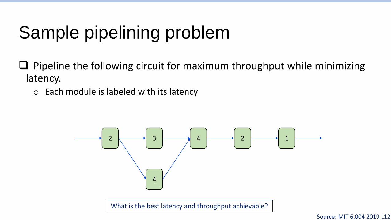
Sample pipelining problem
❑ Pipeline the following circuit for maximum throughput while minimizing latency.o Each module is labeled with its latency
2 3 4 2 1
4
What is the best latency and throughput achievable?
Source: MIT 6.004 2019 L12
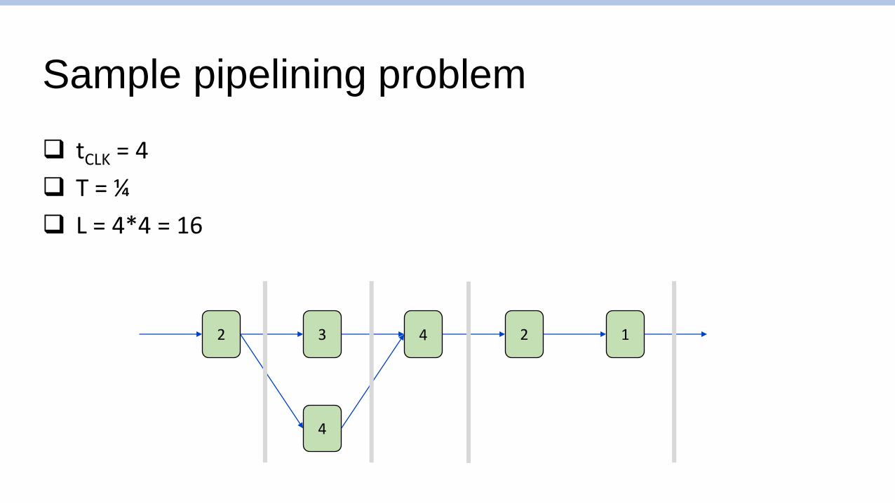
Sample pipelining problem
❑ tCLK = 4
❑ T = ¼
❑ L = 4*4 = 16
2 3 4 2 1
4

When pipelines are not deterministic
❑ Lock-step pipelines are great when modules are deterministico Good for carefully scheduled circuits like a well-optimized microprocessor
❑ What if the latency of F is non-deterministic?o At some cycles, F’s pipeline register may hold invalid value
o Pipeline register must be tagged with a valid flag
o How many pipeline registers should we add to G? Max possible latency?
o What if F and G are both non-deterministic? How many registers?
F
G
HX

FIFOs (First-In First-Out)
❑ Queues in hardwareo Static size (because it’s hardware)
o User checks whether full or empty before enqueue or dequeue
o Enqueue/dequeue in single cycle regardless of size or occupancy
o Does use MUX! Large FIFO has long delay
head
tail
…
DEM
UX M
UXData
Enqueue signal
Full? Empty?
Dequeue signal
Data

Counting cycles: Benefits of an elastic pipeline
❑ Assume F and G are multi-cycle, internally pipelined moduleso If we don’t know how many pipeline stages F or G has, how do we ensure correct
results?
❑ Elastic pipeline allows correct results regardless of latencyo If L(F) == L(G), enqueued data available at very next cycle (acts like single register)
o If L(F) == L(G) + 1, FIFO acts like two pipelined registers
o What if we made a 4-element FIFO, but L(F) == L(G) + 4?• G will block! Results will still be correct!
• … Just slower! How slow? F
G
FX
?
L <- Latency in cycles

Measuring pipeline performance
❑ Latency of F is 3, Latency of G is 1, and we have a 2-element FIFOo What would be the performance of this pipeline?
❑ One pipeline “bubble” every four cycleso Duty cycle of ¾ !
F
G
HX
F
G
*Animation

Aside: Little’s law
❑ 𝐿 = 𝜆𝑊o L: Number of requests in the system
o 𝜆: Throughput
o W: Latency
o Imagine a DMV office! L: Number of booths. (Not number of chairs in the room)
❑ In our pipeline exampleo L = 3 (limited by pipeline depth of G)
o W = 4 (limited by pipeline depth of F)
o As a result: 𝜆 = ¾ ! F
GHow do we improve performance?Larger FIFO, orReplicate G! (round-robin use of G1 and G2)

CS152: Computer Systems ArchitectureProcessor Microarchitecture – Pipelining
Sang-Woo Jun
Winter 2021
Large amount of material adapted from MIT 6.004, “Computation Structures”,Morgan Kaufmann “Computer Organization and Design: The Hardware/Software Interface: RISC-V Edition”,
and CS 152 Slides by Isaac Scherson

Course outline
❑ Part 1: The Hardware-Software Interfaceo What makes a ‘good’ processor?o Assembly programming and conventions
❑ Part 2: Recap of digital designo Combinational and sequential circuitso How their restrictions influence processor design
❑ Part 3: Computer Architectureo Simple and pipelined processorso Computer Arithmetico Caches and the memory hierarchy
❑ Part 4: Computer Systemso Operating systems, Virtual memory

How to build a computing machine?
❑ Pretend the computers we know and love have never existed
❑ We want to build an automatic computing machine to solve mathematical problems
❑ Starting from (almost) scratch, where you have transistors and integrated circuits but no existing microarchitectureo No PC, no register files, no ALU
❑ How would you do it? Would it look similar to what we have now?
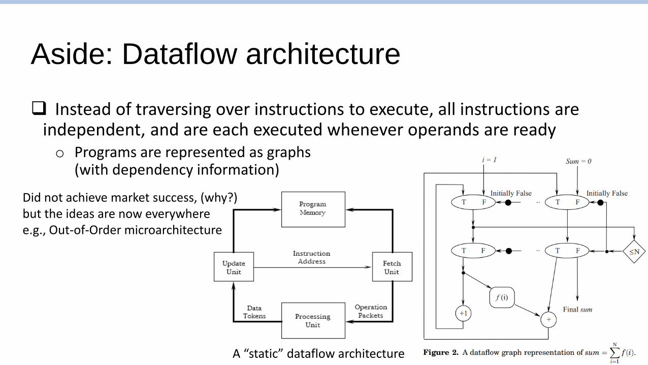
Aside: Dataflow architecture
❑ Instead of traversing over instructions to execute, all instructions are independent, and are each executed whenever operands are readyo Programs are represented as graphs
(with dependency information)
A “static” dataflow architecture
Did not achieve market success, (why?)but the ideas are now everywheree.g., Out-of-Order microarchitecture

The von Neumann Model
❑ Almost all modern computers are based on the von Neumann modelo John von Neumann, 1945
❑ Componentso Main memory, where both data and programs are held
o Processing unit, which has a program counter and ALU
o Storage and I/O to communicate with the outside world
CentralProcessing
Unit
Main Memory
Storage and I/O
Key idea!

Key Idea: Stored-Program Computer
❑ Very early computers were programmed by manually adjusting switches and knobs of the individual programming elementso (e.g., ENIAC, 1945)
❑ von Neumann Machines instead had ageneral-purpose CPU, which loaded itsinstructions also from memoryo Express a program as a sequence of coded
instructions, which the CPU fetches, interprets,and executes
o “Treating programs as data”
ENIAC, Source: US Army photo
Similar in concept to a universal Turing machine (1936)

von Neumann and Turing machine
❑ Turing machine is a mathematical model of computing machines o Proven to be able to compute any mechanically computable functions
o Anything an algorithm can compute, it can compute
❑ Components includeo An infinite tape (like memory) and a header which can read/write a location
o A state transition diagram (like program) and a current location (like pc)• State transition done according to current value in tape
❑ Only natural that computer designs gravitate towards provably universal models
Source: Manolis Kamvysselis

Stored program computer, now what?
❑ Once we decide on the stored program computer paradigmo With program counter (PC) pointing to encoded programs in memory
❑ Then it becomes an issue of deciding the programming abstractiono Instruction set architecture, which we talked about
❑ Then, it becomes an issue of executing it quickly and efficientlyo Microarchitecture! – Improving performance/efficiency/etc while maintaining ISA
abstraction
o Which is the core of this class, starting now

The classic RISC pipeline
Fetch Decode Execute MemoryWriteBack
❑ Many early RISC processors had very similar structureo MIPS, SPARC, etc…
o Major criticism of MIPS is that it is too optimized for this 5-stage pipeline
❑ RISC-V is also typically taught using this structure as well
Why these 5 stages? Why not 4 or 6?

The classic RISC pipeline
❑ Fetch: Request instruction fetch from memory
❑ Decode: Instruction decode & register read
❑ Execute: Execute operation or calculate address
❑ Memory: Request memory read or write
❑ Writeback: Write result (either from execute or memory) back to register

Major components of a microprocessor
Register file
32-bit
x0x1x2x3x4x5
x31
Program Counter
ALU
32-bit
Main memory
ProgramBinary
Working data
……
CPU

A high-level view of computer architecture
CPU
Instruction cache
Data cache
Shared cache
DRAM
Low latency(~1 cycle)
High latency(100s~1000s of cycles)
Will deal with caches in detail later!

Designing a microprocessor
❑ Many, many constraints processors are optimize for, but for now:
❑ Constraint 1: Circuit timingo Processors are complex! How do we organize the pipeline to process instructions
as fast as possible?
❑ Constraint 2: Memory access latencyo Register files can be accessed as a combinational circuit, but it is small
o All other memory have high latency, and must be accessed in separate request/response• Memory can have high throughput, but also high latency
Memory will be covered in detail later!

The most basic microarchitecture
PC
Memory Interface
InstructionDecoder
RegisterFile
ALU
❑ Because memory is not combinational, our RISC ISA requires at least three disjoint stages to handleo Instruction fetch
o Instruction receive, decode, execute (ALU), register file access, memory request
o If mem read, write read to register file
❑ Three stages can be implemented as aFinite State Machine (FSM)
① ② ③Will this processor be fast?Why or why not?

Limitations of our simple microarchitecture
❑ Stage two is disproportionately longo Very long critical path, which limits the clock speed of the whole processor
o Stages are “not balanced”
❑ Note: we have not pipelined things yet!
PC
Memory Interface
InstructionDecoder
RegisterFile
ALU
① ② ③
*Critical path depends on the latency of each component

Limitations of our simple microarchitecture
❑ Let’s call our stages Fetch(“F”), Execute(“E”), and Writeback (“W”)
❑ Speed of our simple microarchitecture, assuming:o Clock-synchronous circuits, single-cycle memory
❑ Lots of time not spent doing useful work!o Can pipelining help with performance?
time
instr. 1
instr. 2
F WE
F WE
Clock cycle due to critical path of Execute
F WE
F WE
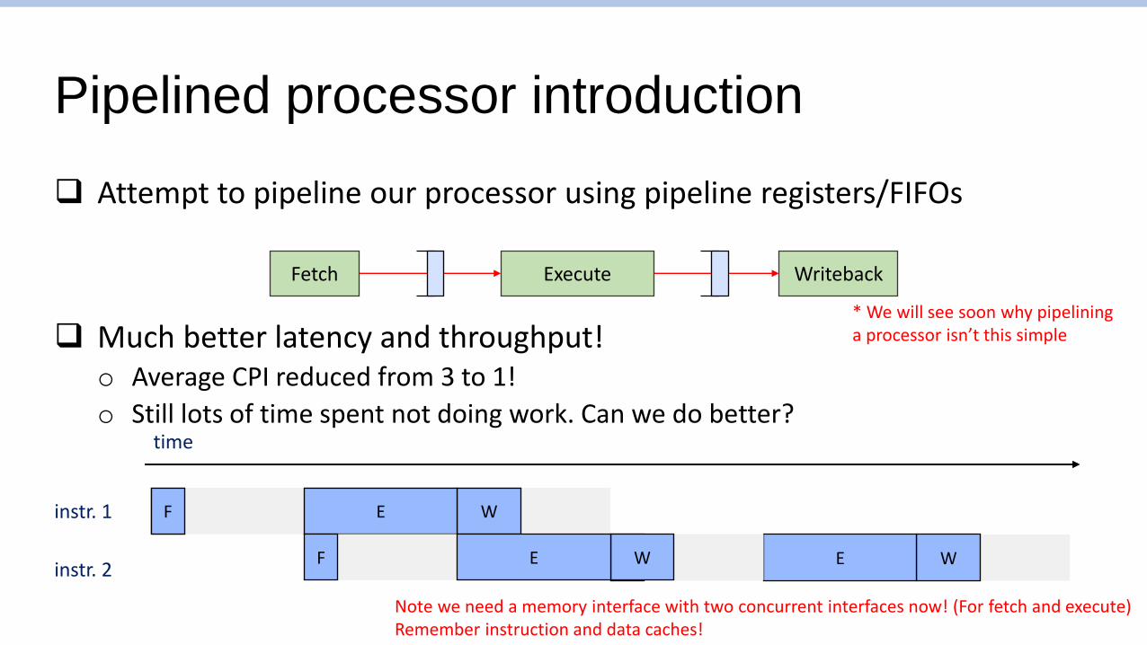
Pipelined processor introduction
❑ Attempt to pipeline our processor using pipeline registers/FIFOs
❑ Much better latency and throughput!o Average CPI reduced from 3 to 1!
o Still lots of time spent not doing work. Can we do better?
Fetch WritebackExecute
time
instr. 1
instr. 2
F WE
F WE
* We will see soon why pipelining a processor isn’t this simple
Note we need a memory interface with two concurrent interfaces now! (For fetch and execute)Remember instruction and data caches!

Building a balanced pipeline
❑ Must reduce the critical path of Execute
❑ Writing ALU results to register file can be moved to “Writeback”o Most circuitry already exists in writeback stage
o No instruction uses memory load and ALU at the same time• RISC!
PC
Memory Interface
InstructionDecoder
RegisterFile
ALU

Building a balanced pipeline
❑ Divide execute into multiple stageso “Decode”
• Extract bit-encoded values from instruction word
• Read register file
o “Execute”• Perform ALU operations
o “Memory”• Request memory read/write
❑ No single critical path which reads and writes to register file in one cycle
Fetch WritebackDecode Execute Memory
Results in a small number of stage with relatively good balance!
Execute

Ideally balanced pipeline performance
❑ Clock cycle: 1/5 of total latency
❑ Circuits in all stages are always busy with useful work
time
Fetch WritebackDecode Execute Memory
Fetch WritebackDecode Execute Memory
Fetch WritebackDecode Execute Memory
instr. 1
instr. 2
instr. 3
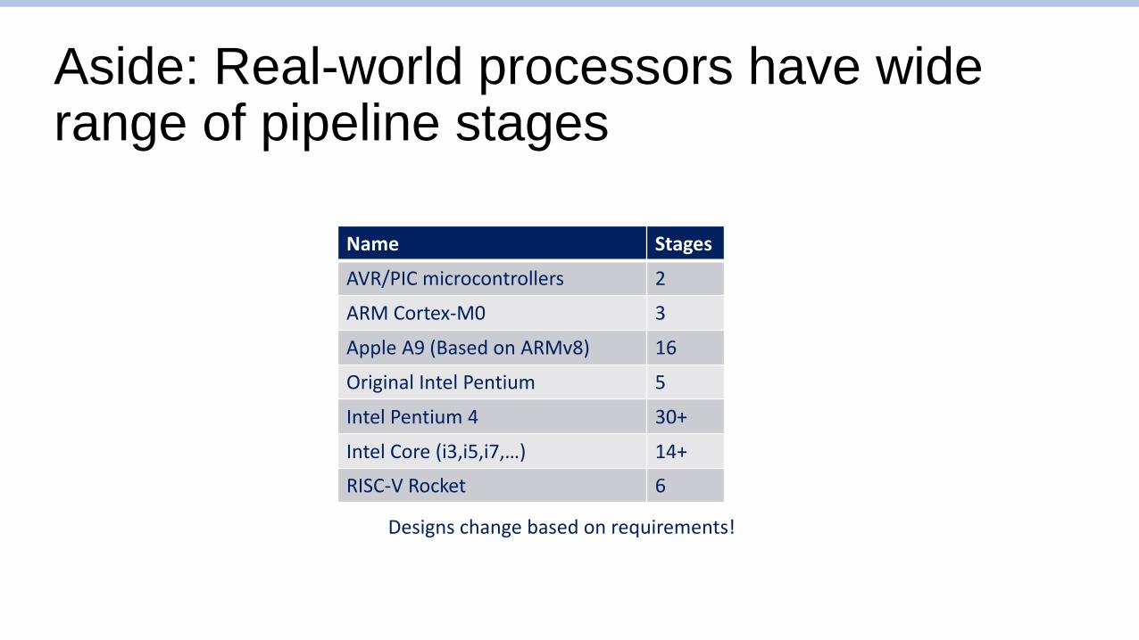
Aside: Real-world processors have wide range of pipeline stages
Name Stages
AVR/PIC microcontrollers 2
ARM Cortex-M0 3
Apple A9 (Based on ARMv8) 16
Original Intel Pentium 5
Intel Pentium 4 30+
Intel Core (i3,i5,i7,…) 14+
RISC-V Rocket 6
Designs change based on requirements!

Will our pipeline operate correctly?
Fetch WritebackDecode Execute Memory
Memory Interface
RegisterFile

A problematic example
❑ What should be stored in data+8? 3, right?
❑ Assuming zero-initialized register file, our pipeline will write zeroWhy? “Hazards”
CS152: Computer Systems ArchitectureAchieving Correct Pipelining
Sang-Woo Jun
Winter 2021
Large amount of material adapted from MIT 6.004, “Computation Structures”,Morgan Kaufmann “Computer Organization and Design: The Hardware/Software Interface: RISC-V Edition”,
and CS 152 Slides by Isaac Scherson

A problematic example
❑ What should be stored in data+8? 3, right?
❑ Assuming zero-initialized register file, our pipeline will write zeroWhy? “Hazards”
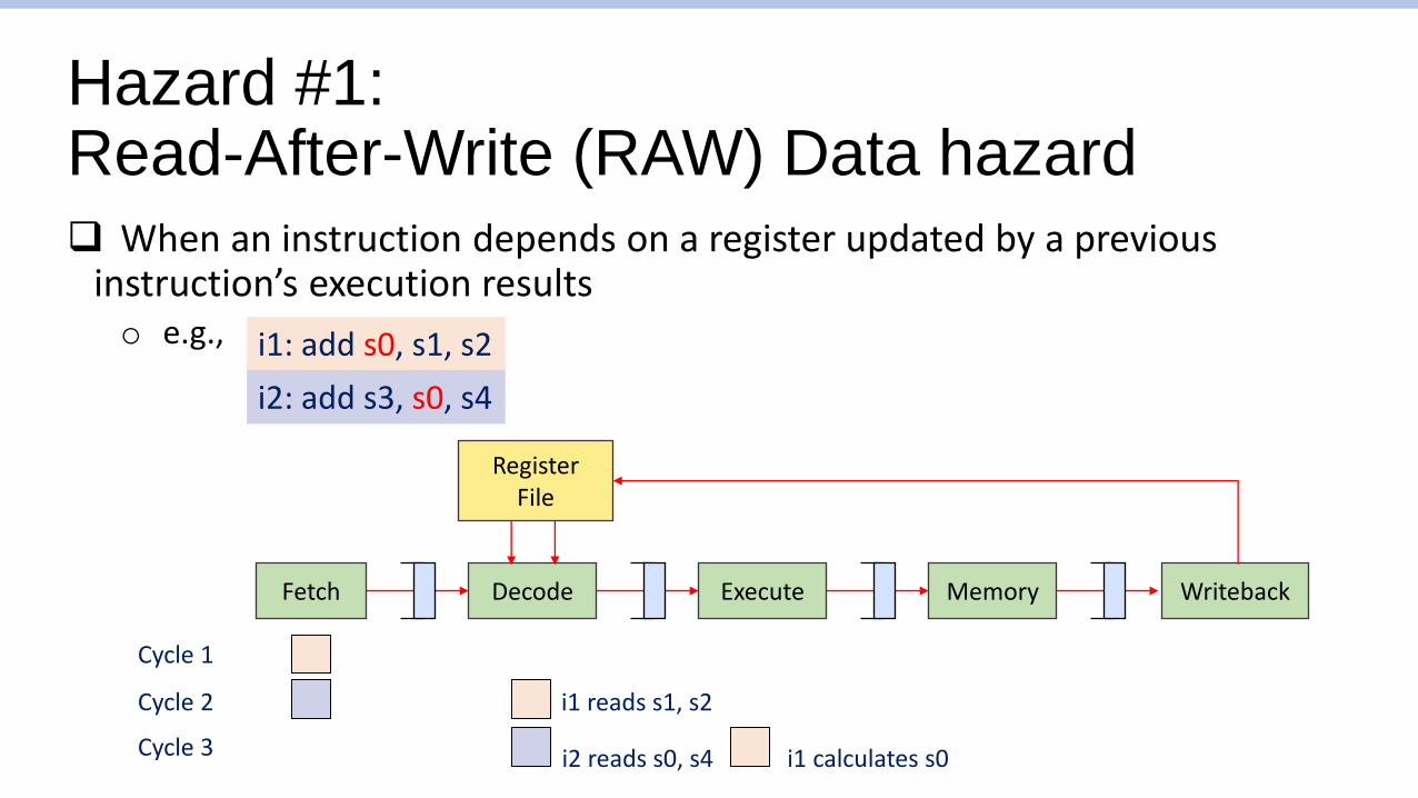
Hazard #1: Read-After-Write (RAW) Data hazard
❑ When an instruction depends on a register updated by a previous instruction’s execution resultso e.g.,
Fetch WritebackDecode Execute Memory
i1: add s0, s1, s2
i2: add s3, s0, s4
RegisterFile
Cycle 1
Cycle 2
Cycle 3
i1 reads s1, s2
i2 reads s0, s4 i1 calculates s0

Hazard #1:Read-After Write (RAW) Hazard
Fetch WritebackDecode Execute Memory
i1: addi s0, zero, 1
i2: addi s1, s0, 0 s0 should be 1, s1 should be 1
Cycle 1 s0 = 0
Cycle 2 s0 = 0
Cycle 3 s0 = 0
Cycle 4 s0 = 0
Cycle 5 s0 = 0
Cycle 6 s0 = 1
i2 reads s0, but s0 is still zero!
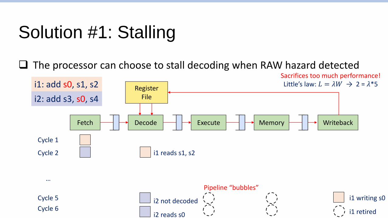
Solution #1: Stalling
❑ The processor can choose to stall decoding when RAW hazard detected
Fetch WritebackDecode Execute Memory
RegisterFile
Cycle 1
Cycle 2
Cycle 5
i1 reads s1, s2
i2 not decoded i1 writing s0
…
Cycle 6
i1: add s0, s1, s2
i2: add s3, s0, s4
i2 reads s0 i1 retired
Sacrifices too much performance!
Pipeline “bubbles”
Little’s law: 𝐿 = 𝜆𝑊 → 2 = 𝜆*5
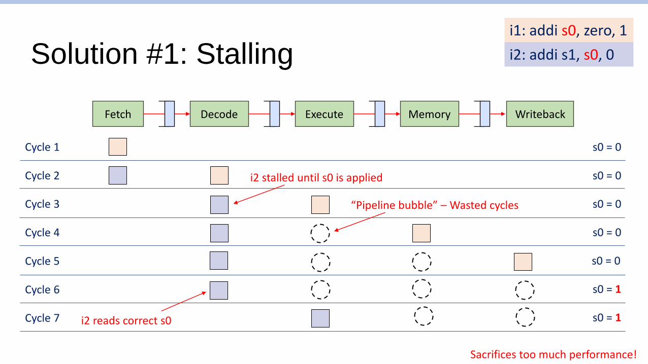
Solution #1: Stalling
Fetch WritebackDecode Execute Memory
i1: addi s0, zero, 1
i2: addi s1, s0, 0
Cycle 1 s0 = 0
Cycle 2 s0 = 0
Cycle 3 s0 = 0
Cycle 4 s0 = 0
Cycle 5 s0 = 0
Cycle 6 s0 = 1
i2 stalled until s0 is applied
Cycle 7 s0 = 1
“Pipeline bubble” – Wasted cycles
Sacrifices too much performance!
i2 reads correct s0

Solution #2: Forwarding (aka Bypassing)
❑ Forward execution results to input of decode stageo New values are used if write index and a read index is the same
Fetch WritebackDecode Execute Memory
RegisterFile
i1: add s0, s1, s2
i2: add s3, s0, s4
Cycle 1
Cycle 2
Cycle 3
i1 reads s1, s2
i2 reads s0, s4 i1 calculates s0
But! Uses new s0 forwarded from execute
No pipeline stalls!

Solution #2: Forwarding details
❑ May still require stalls for a deeper pipeline microarchitectureo If execute took many cycles?
❑ Adds combinational path from execute to decodeo But does not imbalance pipeline very much!
Fetch WritebackDecode Execute Memory
RegisterFile
Instruction bit decode
Register file access
Execute
Combinational path only to end of decode stage!Question: How does hardware detect hazards?

Solution #2:Forwarding
Fetch WritebackDecode Execute Memory
i1: addi s0, zero, 1
i2: addi s1, s0, 0
Cycle 1 s0 = 0
Cycle 2 s0 = 0
Cycle 3 s0 = 0
s0 is still zero, but i1 results forwarded to i2
results forwarded to decode within same cycle
Cycle 4 s0 = 0
Cycle 5 s0 = 0
Cycle 6 s0 = 1
Forwarding is possible in this situation because the answer (s0 = 1) exists somewhere in the processor!

Datapath with Hazard Detection
Not very intuitive… We will revisit with code later

Hazard #2: Load-Use Data Hazard
❑ When an instruction depends on a register updated by a previous instructiono e.g.,
❑ Forwarding doesn’t work here, as loads only materialize at writebacko Only architectural choice is to stall
i1: lw s0, 0(s2)
i2: addi s1, s0, 1
Fetch WritebackDecode Execute Memory
RegisterFile

Hazard #2: Load-Use Data Hazard
Fetch WritebackDecode Execute Memory
Cycle 1 s0 = 0
Cycle 2 s0 = 0
Cycle 3 s0 = 0
i2 stalled until s0 is updated
Forwarding is not useful because the answer (s0 = 1) exists outside the chip (memory)
i1: lw s0, 0(s2)
i2: addi s1, s0, 1
Cycle 4 s0 = 0
Cycle 5 s0 = 0
Cycle 6 s0 = 1
Cycle 7 s0 = 1i2 reads correct s0

A non-architectural solution:Code scheduling by compiler
❑ Reorder code to avoid use of load result in the next instruction
❑ e.g., a = b + e; c = b + f;
lw x1, 0(x0)
lw x2, 8(x0)
add x3, x1, x2
sw x3, 24(x0)
lw x4, 16(x0)
add x5, x1, x4
sw x5, 32(x0)
stall
stall
lw x1, 0(x0)
lw x2, 8(x0)
lw x4, 16(x0)
add x3, x1, x2
sw x3, 24(x0)
add x5, x1, x4
sw x5, 32(x0)
14 cycles20 cycles
Compiler does best, but not always possible!
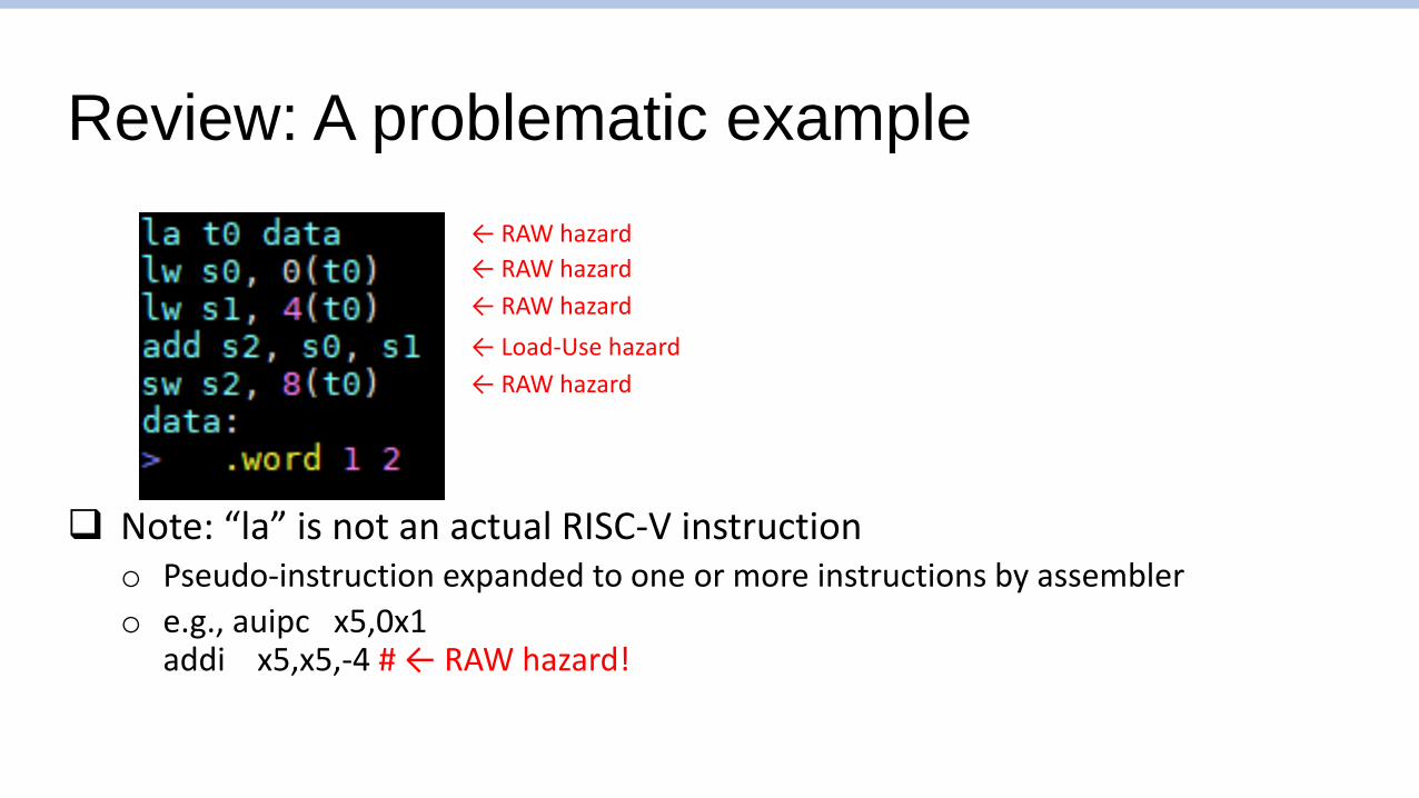
❑ Note: “la” is not an actual RISC-V instructiono Pseudo-instruction expanded to one or more instructions by assembler
o e.g., auipc x5,0x1addi x5,x5,-4 # ← RAW hazard!
Review: A problematic example
← RAW hazard
← RAW hazard
← Load-Use hazard
← RAW hazard
← RAW hazard

Other potential data hazards
❑ Read-After-Write (RAW) Hazardo Obviously dangerous! -- Writeback stage comes after decode stage o (Later instructions’ reads can come before earlier instructions’ write)
❑ Write-After-Write (WAW) Hazardo No hazard for in-order processors
❑ Write-After-Read (WAR) Hazardo No hazard for in-order processors -- Writeback stage comes after decode stage o (Later instructions’ reads cannot come before earlier instructions’ write)
❑ Read-After-Read (RAR) Hazard?o No hazard within processor
Fetch WritebackDecode Execute Memory
read rf write rf3 cycle difference
Dangerous if a later instruction’s state access can happen before an earlier instruction’s access

Hazard #3:Control hazard
❑ Branch determines flow of controlo Fetching next instruction depends on branch outcome
o Pipeline can’t always fetch correct instruction• e.g., Still working on decode stage of branch
Fetch WritebackDecode Execute Memory
PC
i1: beq s0, zero, elsewhere
i2: addi s1, s0, 1
Cycle 1
Cycle 2
Should I load this or not?

Control hazard (partial) solutions
❑ Branch target address can be forwarded to the fetch stageo Without first being written to PC
o Still may introduce (one less, but still) bubbles
❑ Decode stage can be augmented with logic to calculate branch targeto May imbalance pipeline, reducing performance
o Doesn’t help if instruction memory takes long (cache miss, for example)
Fetch WritebackDecode Execute Memory
PC

Aside: An awkward solution: Branch delay slot
❑ In a 5-stage pipeline with forwarding, one branch hazard bubble is injected in best scenario
❑ Original MIPS and SPARC processors included “branch delay slots”o One instruction after branch instruction was executed regardless of branch results
o Compiler will do its best to find something to put there (if not, “nop”)
❑ Goal: Always fill pipeline with useful work
❑ Reality: o Difficult to always fill slot
o Deeper pipelines meant one measly slot didn’t add much (Modern MIPS has 5+ cycles branch penalty!)
But once it’s added, it’s forever in the ISA…One of the biggest criticisms of MIPS

Eight great ideas
❑ Design for Moore’s Law
❑ Use abstraction to simplify design
❑ Make the common case fast
❑ Performance via parallelism
❑ Performance via pipelining
❑ Performance via prediction
❑ Hierarchy of memories
❑ Dependability via redundancy

Control hazard and pipelining
❑ Solving control hazards is a fundamental requirement for pipeliningo Fetch stage needs to keep fetching instructions without feedback from later stages
o Must keep pipeline full somehow!
o … Can’t know what to fetch
Fetch WritebackDecode Execute Memory
Cycle 1
Cycle 2
Fetch PC = 0
Fetch PC = …? Decode PC = 0

Control hazard (partial) solutionBranch prediction
❑ We will try to predict whether branch is taken or noto If prediction is correct, great!
o If not, we somehow do not apply the effects of mis-predicted instructions • (Effectively same performance penalty as stalling in this case)
o Very important to have mispredict detection before any state change!• Difficult to revert things like register writes, memory I/O
❑ Simplest branch predictor: Predict not takeno Fetch stage will keep fetching pc <= pc + 4 until someone tells it not to

Predict not taken example
Fetch WritebackDecode Execute Memory
addi
addi addi
addi addibeq
addi addibeqsw t3
addi addibeqsw t3ret
Pipeline bubbles
addibeqsw t2
Mispredict detected!
Fetch correct branch
No state update before Execute stage can detect misprediction(Fetch and Decode stages don’t write to register)

How to handle mis-predictions?
❑ Implementations vary, each with pros and conso Sometimes, execute sends a combinational signal to all previous stages,
turning all instructions into a “nop”
❑ A simple method is “epoch-based”o All fetched instructions belong to an “epoch”, represented with a number
o Instructions are tagged with their epoch as they move through the pipeline
o In the case of mis-predict detection, epoch is increased, and future instructions from previous epochs are ignored

Predict not taken example with epochs
Fetch WritebackDecode Execute Memory
addi (0)
addi (0) addi (0)
addi (0) addi (0)beq (0)
addi (0) addi (0)beq (0)sw t3 (0)
addi (0) addi (0)beq (0)sw t3 (0)ret (0)
Mispredict detected!
Fetch correct branch
addi (0)beq (0)sw t2 (1) sw t3 (0)ret (0)
epoch = 0epoch = 1
Ignoredret (1) beq (0)sw t2 (1) ret (0)
Ignoredret (1) sw t2 (1)

Some classes of branch predictors
❑ Static branch predictiono Based on typical branch behavior
o Example: loop and if-statement branches• Predict backward branches taken
• Predict forward branches not taken
❑ Dynamic branch predictiono Hardware measures actual branch behavior
• e.g., record recent history (1-bit “taken” or “not taken”) of each branch in a fixed size “branch history table”
o Assume future behavior will continue the trend• When wrong, stall while re-fetching, and update history
Many many different methods, Lots of research, some even using neural networks!

Pipeline with branch prediction
Fetch WritebackDecode Execute Memory
Branch Predictor
PC Next PCFeedback(For dynamic branch prediction)
❑ Branch predictor predicts what should be the next PCo Typically based on the current PC as input
❑ Dynamic branch predictors adapt to program using feedback
❑ If prediction is correct, great! If not, make sure mispredicted instructions don’t effect stateo We looked at the epoch method of doing this (2 bubbles!)

Dynamic branch prediction
❑ Two questions about a PC address being fetchedo Will this instruction cause a branch?
o If so, where will it branch to?
o Both information is needed to predict-fetch a branch
❑ Two architectural entities for predicting the answer to these questionso Branch History Table (BHT)
• Whether this instruction is an instruction, and if it causes a branch
o Branch Target Buffer (BTB)• Which address this instruction will jump to
o (There are many variations – This is just a common example)

Dynamic branch prediction
PC
Branch History Table(BHT)
Branch Target Buffer (BTB)
method Word predict(Word pc) beginWord next_pc = pc + 4;Bit#(10) lsb = truncate(pc);if ( bht[lsb] ) next_pc = btb(lsb);return next_pc;
end
PC + 4
prediction
taken?
Why truncate PC? BHT/BTB is typically small! (2048 elements or so)Different branches may map to same buffer element…
Execute stage updates BHT and BTBwith actual behavior (if it is a branch instruction)

Back to the three questions
❑ Is it a branch instruction?o Execute updates BHT if it is a branch instruction
❑ Is the branch taken?o BHT stores if the branch was taken last time
❑ Where does the branch go?o BTB stores where it went to last time
❑ Of course, all three are merely predictions!

Simple example:1-bit predictor
❑ BHT has one-bit entrieso Most recently taken/not taken
o (“Last time predictor”)
o Does this work well?
❑ How many mispredicts with these taken (T), not taken (N) sequences?o TTTTTNNNNN
o TNTNTNTNTN
o for (i = 0 … 2) {for (j = 0 … 2 ) {}
}
TTTTTNNNNNTNTNTNTNTN
Mispredict at j = 0 (T), j = 2 (N)

Simple example: 2-bit predictor
❑ BHT has two bits – Single outlier does not change future predictionso 00: Strongly not taken, 01: Not taken, 10: Taken, 11: Strongly taken
o Taken branch increases number, not taken branch decreases number
o Counter saturates! Taken after 11 -> 11, Not taken after 00 -> 00
❑ How many mispredicts with these taken (T), not taken (N) sequences?o TTTTTNNNNN
o TNTNTNTNTN
o for (i = 0 … 2) {for (j = 0 … 2 ) {}
}
TTTTTNNNNNInitialized to 01: TNTNTNTNTNInitialized to 10: TNTNTNTNTN
Mispredict once at i = 0 && j = 0 (T), j = 2 (N),
In reality, most SPEC benchmarks record ~90% accuracy with 2-bit predictor

Branch prediction and performance
❑ Effectiveness of branch predictors is crucial for performanceo Spoilers: On SPEC benchmarks, modern predictors routinely have 98+% accuracy
o Of course, less-optimized code may have much worse behavior
❑ Branch-heavy software performance depends on good match between software pattern and branch predictiono Some high-performance software optimized for branch predictors in target
hardware
o Or, avoid branches altogether! (Branchless code)

Aside:Impact of branches
“[This code] takes ~12 seconds to run. But on commenting line 15, not touching the rest, the same code takes ~33 seconds to run.”
“(running time may wary on different machines, but the proportion will stay the same).”
Source: Harshal Parekh, “Branch Prediction — Everything you need to know.”

Aside:Impact of branches
Source: Harshal Parekh, “Branch Prediction — Everything you need to know.”
Slower because it involves two branches

Aside: Branchless programming
Source: Harshal Parekh, “Branch Prediction — Everything you need to know.”