(cs625 advanced computer networks) - recursos voip · umts, release 1999 or r99, standardization...
TRANSCRIPT

IP SUPPORT IN 3G SYSTEMS
(CS625 Advanced Computer Networks)
Prepared By: Snehamoy Banerjee
Assessed By: Dr Dheeraj Sanghi
CONTENTS
Serial Number
Topic Page Number
1.
Introduction
2
2.
Architecture of All-IP Based UMTS System
5
3.
Techniques of Management of User Mobility in Third Generation All –IP Networks
20
4.
Satellite Based UMTS IP Network: SATIN
37
5.
Conclusions
54
6.
References
56
1

INTRODUCTION
With the convergence of Telecommunication Networks and Computer Networks along with the development of mobile systems, we are in to witness a revolution in the near future. Looking into the future, two main drivers for the mobile telecommunications market can be identified: third-generation mobile systems (e.g., UMTS) and the Internet (e.g., the introduction of IP technologies like voice/multimedia over IP in mobile (networks). UMTS is seen as the enabler of wireless multimedia applications and portability of a personalized service set across network/terminal boundaries, as defined within the virtual home environment (VHE) system concept. In light of these recent evolutions, this project investigates the impact of the evolution toward an all-IP UMTS network architecture on the UMTS service architecture, which is based on the VHE concept. The project discusses three main scenarios for supporting IP services in the UMTS service architecture and analyzes their applicability in an all-IP-based UMTS network. The first is based on the traditional centralized VHE concept. The second is the issue of management of mobility issues in such a network. The third id the investigation into the Satellite UMTS, which will widely be used for multicasting applications and the effect of TCP and UDP on satellites. European Telecommunications Standards Institute (ETSI) -- started discussions to cooperate for the production of standards for a third-generation mobile system with a core network based on evolutions of the Global System for Mobile Communications (GSM) and an access network based on all the radio access technologies (i.e., both frequency- and time-division duplex modes) supported by the different partners. This project was called the Third Generation (3G) Partnership Project (3GPP). The American National Standards Institute (ANSI) decided to establish 3GPP2, a 3G partnership project for evolved ANSI/Telecommunications Industry Association (TIA)/Electronics Industry Association (EIA)-41 networks. There is also a strategic group called International Mobile Telecomnications-2000 (IMT-2000) within the International Telecommunication Union (ITU), which focuses its work on defining interfaces between 3G networks evolved from GSM on one hand and ANSI-41 on the other, in order to enable seamless roaming between 3GPP and 3GPP2 networks. 3GPP started referring to 3G mobile systems as the Universal Mobile Telecommunication System (UMTS). In 3GPP, the UMTS specification work was divided into two phases. For the first phase of UMTS, Release 1999 or R99, standardization work was finished around the end of 1999 and the beginning of 2000. As a result, the first phase of UMTS is available in the market since 2001. Whereas the first phase of UMTS was more or less a logical evolution from the 2nd generation system architecture, the second phase, called Release 2000 or R00, is a complete revolution, introducing many new concepts and features. The completion of all standardization work for this second phase was expected around the end of 2001 and the beginning of 2002. This means that commercial operation can be expected around 2004. This project will focus on explaining the UMTS R00 architecture, since this architecture
2

includes the most advanced technologies that will give the user the most complete UMTS multimedia experience. It is now widely recognized that using IP as the foundation for next-generation mobile networks makes strong economic and technical sense, since it takes advantage of the ubiquitous installed IP infrastructure, capitalizes on the IETF standardization process, and benefits from both existing and emerging IP-related technologies and services. The large-scale support of data services and their integration with legacy services are the common objectives of all wireless efforts termed third generation (3G) and beyond. In these all-IP wireless networks, IP can be deployed in two modes: the transport mode and the native mode. As we show in this article, this duality in the use of IP has a significant impact on network efficiency and performance. It is the extended native use of IP in the terrestrial segment of a wireless operator's domain that more readily allows for building a converged network with multiple access technologies. We then discuss the different levels of mobility in the all-IP network. In particular, our focus is on micro mobility, and on the issue of seamless localized mobility within the converged network. After reviewing the mobility schemes that have emerged in recent years, we describe a hierarchical mobility management scheme based on multi protocol label switching. The scheme employs an enhanced type of MPLS routers, called label edge mobility agents, and is scalable, efficient, and flexible. It directly inherits the noted capabilities of MPLS in terms of support of QoS, traffic engineering, advanced IP services, and fast restoration. This scheme does not use nodes that are specific to any given wireless technology, and is well suited for gradual deployment. There are certain differences in the approaches to specific aspects of the 3G-network architecture; the most pronounced being those between the specifications introduced by the Third Generation Partnership Projects (3GPP and 3GPP2), the leading wireless industry consortia. However, the goals of the present stage of the wireless evolution remain common and include IP-based multimedia services, IP-based transport, and the integration of Internet Engineering Task Force (IETF) protocols for such functions as wide-area mobility support (e.g., Mobile IP), signaling (e.g., SIP), and authentication, authorization, and accounting, or AAA (e.g., RADIUS, Diameter). It is becoming popular to call any network that meets these criteria an all-IP network. Henceforth, in this project we restrict our discussion to the Universal Mobile Telecommunications System (UMTS) branch of the 3G evolution (as specified by 3GPP) with the understanding that similar principles may be applied to other 3G wireless architectures as well. Accordingly, we provide a brief review of the underlying UMTS concepts in order to develop an all-IP network model and to explain the benefits of using IP and IP-related technologies such as multi protocol label switching (MPLS) in such networks. Efficient support of Internet-based applications to mobile/nomadic users is a key feature of the third-generation (3G) networks. In light of the shortage and the high cost of the T-UMTS (Terrestrial UMTS) spectrum, the operators are looking into the provision of integrated broadcast/multicast services through hybrid broadcast-UMTS systems. S-UMTS (Satellite UMTS) could play an important role in the efficient delivery of some UMTS services to which it is better suited. These services include broadcasting and
3
multicasting applications such as audio/video, e-newspaper and live stock exchange data. The level of IP penetration into 3G networks is a decisive factor for the design of an efficient system, optimized for the delivery of these services. The paper identifies the respective requirements arising for the S-UMTS air interface, in the frame of the architecture scenarios envisaged within the EU IST project SATIN. One thing is important to note that, we shall be discussing inferred principles and not actual principles. These inferences have largely been drawn from various specifications and RFCs. It is highly possible that alternate better solutions could be inferred. While the subject is very vast and thousands of researchers are working round the globe, a limited amount of topics have been covered especially those, which are seen from a communication point of view but is useful to a computer scientist also. Subjects on IP transport over ATM and IPSEC have been left as either adequate references are readily available or are a subject of separate project altogether.
4

ARCHITECTURE OF ALL-IP BASED UMTS SYSTEM
INTRODUCTION Since mid-1999 two remarkable trends appeared in 3GPP UMTS standardization. The first trend was the shift toward an all-IP UMTS network architecture. This shift formed the basis for the R00 specifications. More specifically, the R00 all-IP UMTS specifications replace the circuit-switched transport technologies, which were still used in UMTS R99, by packet-switched transport technologies and introduce multimedia support in the UMTS core network. The second trend was the evolution toward an open service architecture (OSA). This concept of service portability was called the virtual home environment (VHE) in 3GPP standardization. In light of the recent evolutions in 3G standardization, this project further investigates the synergy between the two trends mentioned above: on one hand, the trend in the design of the UMTS network architecture to move toward an all-IP approach, and on the other, the trend in the design of the UMTS service architecture to standardize open network interfaces. The goal of the project is to clarify the implications of an IP-based core network design on the UMTS service architecture and to analyze possible evolution paths, integrating both network and service aspects, toward a complete all-IP UMTS system architecture. The next section gives an introduction to the VHE concept and its realization via OSA interfaces. This is followed by an introduction to voice over IP (VoIP) in mobile networks and explain how VoIP can be supported in the all-IP UMTS core network architecture. The section then further analyzes the impact of an IP-based core network design on the UMTS service architecture. Two possible scenarios are discussed for supporting VoIP services in the UMTS service architecture based on the principles of the VHE. Finally, the section concludes by evaluating the coexistence of both scenarios: the classical centralized – intelligent network (IN) type -- service control architecture and the new decentralized (OSA) type service provisioning architecture.
5

INTRODUCTION TO THE VIRTUAL HOME ENVIRONMENT THE VHE CONCEPT: STANDARDIZING SERVICE CAPABILITIES INSTEAD OF SERVICES In the beginning of the 1990s, UMTS was defined in Europe as the third-generation mobile telecommunications system that would replace the current GSM standard. The main goal of UMTS is to offer a much more attractive and richer set of services to the user.
Figure 1: The Virtual Home Environment In order to achieve a sufficient degree of service differentiation, UMTS needed three fundamental architectural improvements from GSM: Wideband access: Higher bit rates over the air open the path toward mobile multimedia applications. Mobile- fixed-Internet convergence: There is a need for a uniform way to offer users cross-domain services. An example is the tracking of a user's location in the mobile, fixed, and Internet domains and automatically adapting the content of his incoming messages to SMS, voice message, fax, or email. VHE is the enabler of this service portability across networks and terminals in the different domains.
6
Flexible service architecture: By standardizing not the services themselves but the building blocks that make up services, UMTS shortens the time to market for services from GSM and enhances creativity/flexibility when inventing new services. 3GPP defined the VHE as "a system concept for personalized service portability across network boundaries and between terminals." The aim was to enable end users to access the services of their home network/service provider even when roaming in the domain of another network provider, thus making them feel "virtually at home." VHE allows a user to personalize the set of services for which he/she has a subscription with his/her home network, and provides these home services with the user's personalized "look and feel" across different types of networks -- mobile, public switched telephone network (PSTN), Internet -- and terminals -- mobile, laptop, fixed phone, PDA, PC -- he/she might be using. An example of one of the personal service settings of a user could be "from 0900h to 1700h I want to be alerted for incoming messages from my boss." The VHE will automatically adapt the type of messaging used to reach the user to the capabilities of the terminal and network the user is using at that time: if the user is using a Wireless Application Protocol (WAP) terminal but is not roaming in a network that supports WAP, the VHE will convert the message into another format (e.g., SMS). VHE, currently still under standardization in 3GPP, promotes the view (Fig. 1) that the UMTS service architecture should be a layered architecture enabling services to be developed independent of the underlying networks. This is achieved by standardizing the interfaces between the so-called network layer, comprising all network elements under the operator's control, and the service layer, comprising third-party servers running service logic. In this way the main goal of the separation between the network and service layers can be achieved: to allow faster, easier, and more flexible creation, deployment, and operation of new personalized applications/services. The VHE specification introduces some new terminology related to the way this new open interface between the network and service layers, called the OSA interface, is realized (Fig. 1). Service capability servers (SCSs) are defined as all those servers in the network that provide functionality used to construct services. From a software point of view, the OSA interface is defined as an object-oriented application-programming interface (API). This means that all the functionality, which can be provided by SCSs, is grouped into logically coherent software interface classes. If we take the mobile switching center (MSC) as an example of an SCS, call control is a class consisting of several call control related functions, for example, "create a new call leg," "connect call leg A to call leg B" ... The classes of the OSA interface are called service capability features (SCFs) in the VHE specifications. Practically speaking, the SCFs are not implemented as a new standalone box in the architecture; instead, they are just added as an additional software layer of interface classes on top of existing network elements, which are then called SCSs. By providing services in the service layer access to the SCFs of all the SCSs in the network layer, OSA aims to offer a secure open standardized interface for service providers toward underlying networks. Security is ensured by additional authentication, authorization, accounting, and management interfaces toward all the SCSs. The service logic constructed
7
according to this OSA principle resides in so-called application servers in the service layer. The SCSs and application servers are interconnected through, say, an IP-based network, which allows for distributed deployment of the SCSs and application servers. To summarize, the purpose of the SCFs/SCSs is to:
• Raise the abstraction level of the network interfaces toward service providers and simplify application development. The SCFs offer a generalized view of the network functionality to third party application developers via standardized interfaces.
• Hide network-specific protocols and offer connectivity to both circuit-switched and IP networks.
• Protect core networks from misuse via authentication, authorization, accounting, and management interfaces toward all the SCSs
THE UMTS SERVICE ARCHITECTURE: OPEN STANDARDIZED INTERFACES ON TOP OF SERVICE CAPABILITY SERVERS As explained previously, VHE defines SCSs and standardizes SCFs that the SCSs can provide to third party service providers to design new services (Fig. 1). Examples of SCFs are call control, location/positioning, and notifications. The functionality represented by the SCFs is offered via an open standardized interface, the OSA interface, toward the service layer above and is implemented by the underlying transport networks using GSM/UMTS protocols. Examples of such GSM/UMTS protocols are Mobile Application Part (MAP), CAMEL Application Protocol (CAP), and WAP. As identified in R99 of the 3GPP VHE specification, the SCSs and their roles in service provisioning are: Control servers: As SCSs they offer mechanisms for applications to access basic bearer· UMTS call /call control capabilities. Since R99 only supports circuit-switched telephony, the only call control element is the MSC. The 24.08 CC protocol is the UMTS call control protocol. Home location register (HLR): The HLR is an intelligent database that contains the location and subscriber information of all subscribers of the network to which it belongs. The MAP protocol allows the exchange of location and subscriber information between different network element. Mobile execution environment (MExE) server: The mobile execution environment is the execution environment, which can be a Java Virtual Machine or a WAP browser, in the terminal. Value-added services are offered through a client/server relationship between the MExE server in the network and the MExE client in the terminal. WAP is a protocol designed to provide services to mobile terminals taking into account their limited capabilities; display, processing power, and so on. Wireless Telephony Application (WTA) is an extension to WAP that allows WAP applications to use telephony related functionality in the terminal and the network.
8

SIM application toolkit (SAT) server: SAT is a mechanism that offers additional capabilities to the communication protocol between the subscriber identity module (SIM) card and mobile terminal. A SIM card is the smart card inserted in the mobile terminal. The SIM card contains on one hand certain subscriber and security related information used by the mobile network to authenticate the user and, on the other, some small applications (e.g., phone book, calendar, electronic wallet). The most important additional capabilities supported by SAT are the pro-active commands from SIM card to terminal; for example, the SIM card can instruct the terminal to download information. Via the SAT server the operator can control existing SAT applications on the SIM card and download new SAT applications to the SIM card. Customized Application for Mobile Networks Enhanced Logic (CAMEL) server: CAMEL extends the scope of IN service provisioning to the mobile environment. CAMEL allows the provisioning of certain IN services (e.g., prepaid) to mobile networks and enables the exchange of mobile-specific service information, for example, related to SMS or GPRS, between the CAMEL network elements, the service switching point (SSP) and service control point (SCP). CAMEL services are invoked via triggers, which are contained in the SSP inside the MSC, to in SCP residing in CAMEL service environment (CSE).
Figure 2: Mapping of SCFs to the network.
9
There is not necessarily a relationship between the different SCSs. Some simple services only require a UMTS bearer. For other services, like WAP, an MExE server is essential. For location-based services it is necessary to consult the HLR, and if you want to provide IN services to mobile phones CAMEL is needed. To give a practical example, Fig. 2 illustrates how services can be delivered in the UMTS R99 architecture; by the home network operator as well as third party service providers. Traditionally network operators provide services via servers (e.g., MSC, SCP, HLR, MExE server, SAT server,) and protocols (e.g., MAP, CAP, WAP, SAT) controlled completely from inside the operator’s private network/service environment. The IE novelty of the UMTS service architecture is that, via the OSA interfaces toward the operator’s SCSs, third pasty service providers can also start offering services. In this case the actual service logic is run on application servers in the third party domain, but it uses capabilities of the underlying network that it can access via the OSA interfaces toward the operator’s SCSs.
AN INTRODUCTION TO VOIP IN MOBILE
WHY IS IP TECHNOLOGY INTERESTING FOR OPERATORS AS WELL AS END USERS?
It is believed that IP will be capable of carrying all types of data, including real-time data like voice. Using VoIP has several advantages over traditional telephony. For network operators it means lower equipment cost and management of the network. Using VoIP with techniques like silence suppression can result in a bandwidth gain of a factor of four compared to 64 kb/s PCM connections. This, in turn, can result in lower communication costs to users.
The use of end-to-end IP sessions with higher bandwidths as in UMTS opens the path for mobile end users to a whole new set of multimedia over IP services such as videoconferencing, personal guidance systems, and network games. These services are believed to be some of the main drivers for UMTS. Using the same technology (i.e., IP services) in fixed and mobile networks facilitates interworking between both types of networks; also, the development and creation of new services is provided in a consistent way. A big technological challenge still to be solved in the context of real-time VoIP services is the provisioning of sufficient QoS, especially in the context of mobile networks, to control delays introduced by handover, manage scarce radio resources, and perform admission control.
THE ALL-IP UMTS SOLUTION
The major innovation of R00 is the introduction of the IP multimedia domain. The following section concentrates on R00. The following new features are introduced in Release 2000:
• Provisioning of IP-based multimedia services as an extension of the packet-switched services.
10
• Enabling a bearer-independent circuit-switched network architecture. Circuit-switched transport is replaced by packet-based network transport.
• IP transport within the UTRAN (i.e., on Iub and Iur). • Network architecture is independent of the transport layer, which can be based on
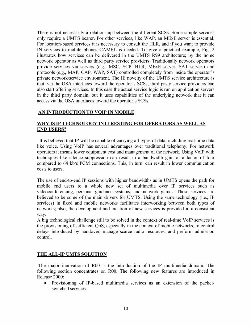
either ATM or IP. In the context of this article, an all-IP solution for UMTS refers to an all-IP core network (Fig. 3). In the all-IP core network, all data is transported on IP, including even traditional circuit-switched voice data. R00 supports two types of real-time services. The first is a circuit-switched voice service, and the second is an IP-based multimedia service. In the R00 specification, the classical MSC is split into a control part, the MSC server, and a transport part, the media gateways.
Figure 3: A Simplified All-IP Architecture. The requirements for an all-IP core network are summarized as follows:
• Support of roaming and handover to 2G networks (e.g., GSM, GPRS).
11

• Support of 3G circuit-switched terminals in a full IP UMTS core network, providing backward compatibility with R99 terminals.
• Support of new (e.g., IP and multimedia) as well as existing services, such as speech, SMS, and supplementary IN services. Support of legacy services is required since subscribers accustomed to the services in GSM may not be willing to sacrifice these services when migrating or roaming toward the new UMTS system.
The second requirement implies that there will be three types of 3G mobile terminals: circuit-switched, packet-switched (IP), and those that support both modes. Both circuit- and packet-switched modes are supported at the radio interface. The circuit-switched mode is used for traditional circuit-switched terminals and makes optimal use of the radio resources for voice services. Circuit-switched voice is optimized in terms of both bandwidth (small frame protocol overhead) and quality (the code rate is adapted to the radio link quality, and every voice sample is split into three streams, each with a different level of error protection/correction). The packet-switched mode is more flexible in terms of services supported and allows the introduction of multimedia applications, but is less efficient in terms of bandwidth consumption due to the IP header overhead over the radio. There are two major protocols for supporting VoIP: SIP, standardized by the IETF, and H.323, standardized by the ITU. 3GPP has decided to use only SIP as the call control protocol between terminals and the mobile network. Interworking with other H.323 terminals (e.g. fixed H.323 hosts) will be performed by a dedicated server in the network. Figure 3 shows the proposed 3GPP all-IP UMTS core network architecture. New elements in this architecture are: • MSC server: The MSC server controls all calls coming from circuit-switched mobile
terminals and mobile terminated calls from a PSTN/ISDN/GSM network to a circuit-switched terminal. The MSC server interacts with the media gateway control function (MGCF) for calls to/from the PSTN. R00 introduces the functional split of the MSC, where the call control and services part is maintained in the MSC server, and the switch is replaced by an IP router (MG). This functional split reduces the deployment cost and guarantees the support of all existing services.
• Call state control function (CSCF): The CSCF is a SIP server that provides/controls multimedia services for packet-switched (IP) terminals, both mobile and fixed.
• MG at the UTRAN side: The MG transforms VoIP packets into UMTS radio frames. The MG is controlled by the MGCF by means of Media Gateway Control Protocol H.248.The media gateway is added to fulfill requirement two. In Fig. 3, the MG is drawn at the UTRAN side of the Iu interface, so the Iu interface, between the core network and UTRAN, is IP-based. The MG can also be located at the core network side of the Iu interface. In this case, the Iu interface remains unmodified from R99, without impact on the UTRAN.
• MG at the PSTN side: All calls coming from the PSTN are translated to VoIP calls for transport in the UMTS core network. This MG is controlled by the MGCF using the H.248 protocol.
• Signaling gateway (SG): An SG relays all call-related signaling to/from the PSTN/ UTRAN on an IP bearer and sends the signaling data to the MGCF. The SG does not perform any translation at the signaling level.
12
• MGCF: The first task of the MGCF is to control the MGs via H.248. Also, the MGCF performs translation at the call control signaling level between ISUP signaling, used in the PSTN, and SIP signaling, used in the UMTS multimedia domain.
• Home subscriber server (HSS): The HSS is the extension of the HLR database with the subscribers' multimedia profile data.
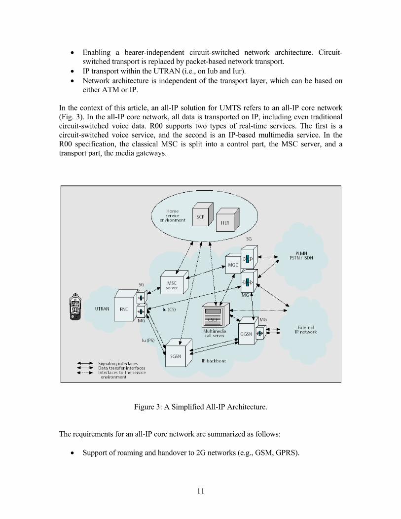
For the transport of data traffic, UMTS uses the General Packet Radio Service (GPRS) network. For voice calls, there are two options: for packet switched mobile terminals, voice data is transported over the GPRS network using the GPRS Tunneling Protocol (GTP) on top of IP. All mobility is solved by the GPRS protocols. For circuit-switched mobile terminals, voice samples are transported over IP between the MGs using the Iu Frame Protocol (FP). In the latter case there is no GTP tunneling; hence, mobility has to be solved in a different way, namely by MG handovers. TWO POSSIBLE SCENARIOS FOR PROVIDING VOIP SERVICES IN VHE For several years the boundary between mobile operators and Internet service providers has been blurring due to cross-area expansion (VoIP, mobile IP, GPRS, WAP). The requirement to open the UMTS network to service providers will accelerate even more the envelopment and deployment of services that combine telecom and datacom features (e.g., VoIP, MMoIP). As explained above, the UMTS architecture is enhanced in R00 to also cover VoIP/MMoIP services. Let us again study the R00 all-IP architecture (Fig. 3), as explained previously, and try to map this to the concept of VHE (Fig. 1), which was explained earlier. Note that Fig. 1 represents the R99 view of VHE and Fig. 3 the R00 all-IP architecture. Comparing Fig. 1 and Fig. 3 we can easily detect that, in order to derive the R00 VHE picture, a new additional call control element needs to be added to Fig. 1 to incorporate the novelties of the R00 all-IP architecture shown in Fig. 3. In Release 1999 the only call control element was the MSC providing circuit-switched telephony services. In Release 2000 there are two call control elements: the MSC server for delivering traditional circuit switched telephony services, and the CSCF or SIP server for delivering the new VoIP/MMoIP services. Since the R99 MSC is simply split into two parts (MSC server and MG) in R00, without any major functional changes, circuit-switched services can be provided in exactly the same way as in R99: via the CAMEL platform. The CSCF, on the other hand, is a call control element not present in R99 at all, introducing totally new multimedia capabilities. Since there is no standard way yet in mobile history to provide multimedia services via a CSCF, several possible options could be explored. As suggested in Figure 4, there are two possible scenarios for the deployment of VoIP services. VoIP services can be provided based on either classical IN/CAMEL service control via the operator's SCP (A in Fig. 4) or third party call control mechanisms (B in Fig. 4). For the latter case, an open standardized interface directly on top of the CSCF is needed. This OSA interface can be implemented in several ways, using, for example, CGI,
13

CPL, or even SIP. In the following paragraphs, the two scenarios and their impact on the UMTS service architecture will be explained in further detail.
Figure 4: mapping of SCFs to the network architecture. SCENARIO A: THE "SOFTSSP" CONCEPT; INAP/CAP SUPPORT OF VOIP IN is a mechanism designed for operators to control the provisioning of services in their networks from a centralized point, the SCP, outside of the switch network. IN relies on SSPs in the switches to trigger the SCP via the IN Application Part (INAP) protocol when IN service control is needed. The main advantage of IN is that it offers operators a much more scalable service platform, which allows them to introduce new services in a more flexible and faster way. With the success of GSM, a mobile version of IN, CAMEL, was designed. The equivalent of INAP for IN is the CAMEL Application Part (CAP). IN and CAMEL were developed in several releases, each new IN/CAMEL version supporting new functionality. The power of IN/CAMEL lies in the degree of complexity of the SSP and INAP/CAP. In order to be able to provide the correct triggers to the SCP, the SSP contains a mapping that determines which point in the MSC call state model needs to trigger which point in the state model of the IN/CAMEL service logic. The more complex
14
this mapping, the more complex services can be provided. This means that in order to provide services via IN/CAMEL on a SIP server, all you need to do is develop an SSP on top of the SIP server: a mapping between the SIP call state model and the state model of the IN/CAMEL service logic. This kind of SSP is called a "SoftSSP." Concentrating again on mobile networks, it is clear that the main advantage of this SoftSSP approach (A in Fig. 4) is that the operator's R99 investments in CAMEL can be reused to provide VoIP services on a CSCF. When designing an R00 SoftSSP for SIP call control, many traditional auxiliary processes, such as database handling and billing, can be reused from the R99 SSP for circuit-switched call control. Either they can be retained completely as they are, or they need some enhancement to reflect functionality specific to multimedia. The interface between the CSCF and the SoftSSP call control processes must:
• Carry sufficient call data for the SoftSSP to function correctly and to deliver the necessary information to the SCP so that service logic decisions can be made.
• Allow the SCP in combination with the SoftSSP to control VoIP calls (e.g., change "B" party address, add/subtract media components) and to manipulate call information (e.g., presentation number)
This scenario -- with SCP control of both existing CAMEL services and new VoIP services -- can offer some advantages for existing operators since they already own a traditional (UMTS R99 or even GSM) circuit-switched network controlled by a CAMEL service platform. In the SoftSSP scenario all applications, for legacy as well as new VoIP/MMoIP services, can be created according to the same proven CAMEL service creation environment methods. Based on a dedicated mapping between CAP and SIP call control, VoIP/MMoIP services are, just like traditional CAMEL services, under control of the operator's SCP. In this scenario, third party service providers can get access to the operator's network via the OSA interfaces only via a central access point, the SCP. Third party service providers cannot get direct access to the CSCF. The fact that in this scenario third party service provisioning always relies on the operator's underlying CAMEL network implies that, in the development of new VoIP/MMoIP services, third party service providers are inevitably limited by the capabilities of the CAMEL version supported by the network operator. This is a serious drawback of this approach since it slows down the introduction of new VoIP/MMoIP services to the speed of CAMEL standardization.
SCENARIO B: DIRECT "THIRD PARTY CALL CONTROL"; OSA SUPPORT OF VOIP (VIA CGI/CPL OR SIP) SIP allows for new services to be defined through a few powerful third-party call control mechanisms. There are two mechanisms, other than SIP itself, that allow a third party to instruct a network entity to create and terminate calls to other network entities: Common Gateway Interface (CGI) or Call Processing Language (CPL).
15
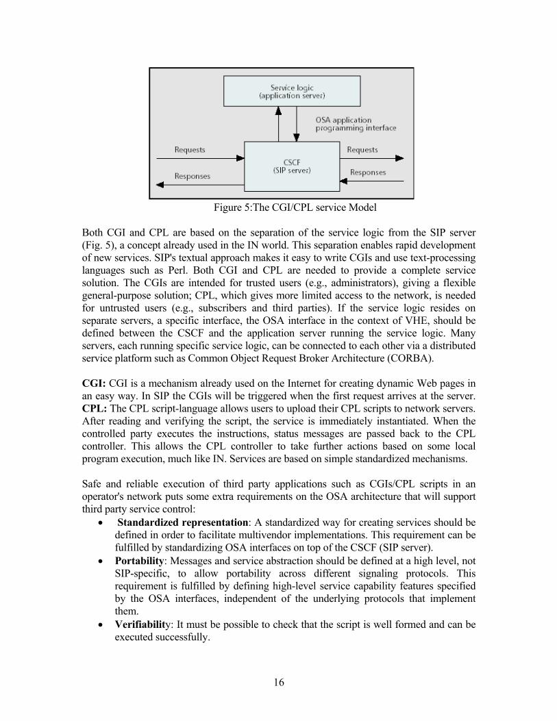
Figure 5:The CGI/CPL service Model
Both CGI and CPL are based on the separation of the service logic from the SIP server (Fig. 5), a concept already used in the IN world. This separation enables rapid development of new services. SIP's textual approach makes it easy to write CGIs and use text-processing languages such as Perl. Both CGI and CPL are needed to provide a complete service solution. The CGIs are intended for trusted users (e.g., administrators), giving a flexible general-purpose solution; CPL, which gives more limited access to the network, is needed for untrusted users (e.g., subscribers and third parties). If the service logic resides on separate servers, a specific interface, the OSA interface in the context of VHE, should be defined between the CSCF and the application server running the service logic. Many servers, each running specific service logic, can be connected to each other via a distributed service platform such as Common Object Request Broker Architecture (CORBA). CGI: CGI is a mechanism already used on the Internet for creating dynamic Web pages in an easy way. In SIP the CGIs will be triggered when the first request arrives at the server. CPL: The CPL script-language allows users to upload their CPL scripts to network servers. After reading and verifying the script, the service is immediately instantiated. When the controlled party executes the instructions, status messages are passed back to the CPL controller. This allows the CPL controller to take further actions based on some local program execution, much like IN. Services are based on simple standardized mechanisms. Safe and reliable execution of third party applications such as CGIs/CPL scripts in an operator's network puts some extra requirements on the OSA architecture that will support third party service control:
• Standardized representation: A standardized way for creating services should be defined in order to facilitate multivendor implementations. This requirement can be fulfilled by standardizing OSA interfaces on top of the CSCF (SIP server).
• Portability: Messages and service abstraction should be defined at a high level, not SIP-specific, to allow portability across different signaling protocols. This requirement is fulfilled by defining high-level service capability features specified by the OSA interfaces, independent of the underlying protocols that implement them.
• Verifiability: It must be possible to check that the script is well formed and can be executed successfully.
16

• Completion: Once a service is initiated it must be sure it can be terminated. • Safety of execution: The service should not be able to initiate unsafe actions, such
as modifying the data of other users. The last three requirements are fulfilled by incorporating specific security, authentication, and verification mechanisms in the OSA interface definition. The scenario of third party call control, which does not have centralized SCP control of both CAMEL and VoIP services, is very interesting for third party service providers and new UMTS operators. Using CPL/CGI or SIP, service logic can be downloaded and controlled directly in the operator's SIP server by third party application servers. In this scenario, VoIP/MMoIP services are created, provisioned, and managed completely independent of the classical CAMEL services, which are still controlled via the SCP. The OSA interfaces on the SCP are used for third party control of legacy CAMEL services. The OSA interfaces on the CSCF itself allow third party service providers to control VoIP services directly via the CSCF in the operator's network. An advantage of an OSA interface directly on the CSCF is that the deployment of VoIP services does not depend on the evolution of future releases of the CAMEL capability sets. TOWARD A FULLY INTEGRATED ALL-IP SERVICE ARCHITECTURE Two possible scenarios were explained above that can be used to provide VoIP/MMoIP services in the UMTS all-IP architecture; OSA interfaces on top of the operator's SCP or OSA interfaces directly on top of the CSCF. In this section we will explore in more detail the advantages and drawbacks of these two competing scenarios. To conclude, we evaluate which architecture would finally best suit an operator that wants to provide its customers an integrated package of both legacy and new VoIP/MMoIP services.
Table 1: Advantages and drawbacks of the two provisioning scenarios. The left column of Table 1 investigates the scenario where both legacy services and new VoIP/MMoIP services are provided using only a CAP interface on the CSCF, and the right
17

column of Table 1 explores a scenario where only OSA interfaces are available on top of the CSCF. As can be seen from the table, both scenarios have their merits. To support legacy CAMEL services, clearly CAP interfaces are needed on top of the CSCF. On the other hand, creation of new VoIP/MMoIP services would benefit from having OSA interfaces directly on the CSCF. Therefore, both types of interfaces will coexist, and the solution will lie in the optimal selection of the type of interface most suitable to provide that particular service. According to the concept of VHE, users' access to their personalized set of services depends on the capabilities supported by the terminal and networks involved in service delivery. For a roaming user, it is sensible to assume that there is a difference in the capabilities supported by the home network and the visited network. In such a case, the home network should compare the differences in the supported capabilities of the home and visited networks. Based on this comparison, the home network should make the selection of the most suitable environment and/or interfaces to be used for service delivery. For example, if the service requested by the roaming user is a legacy service (e.g., prepaid) which can be perfectly supported by CAMEL and the visited network supports the necessary version of CAMEL, the home network may decide to leave call control to the visited network. In the case of a third party service provider, the service logic, which can be provided by an OSA interface on top of the CAMEL SCP in the home network, communicates with the call control in the visited network by means of the standardized CAP protocol between the home and visited networks. If, on the other hand, the service requested by the roaming user is a new VoIP/MMoIP service (e.g., multimedia conferencing), which cannot be supported by the CAMEL capabilities of the visited network, the home network may decide to handle call control in the home network. In the case of a third party service provider, the service logic, which can be provided by an OSA interface on top of the CSCF in the home network, communicates with the call control in the home network by means of an OSA interface directly on top of the CSCF in the home network. From the previous analysis we can conclude the following. An operator that wants to provide its customers an integrated package of both legacy and new VoIP/MMoIP services needs an architecture that allows him to flexibly switch between both mechanisms; service control via CAP as well as service control via OSA interfaces directly on top of network elements. To conclude, Fig. 6 presents an overview of such a "fully integrated" UMTS service architecture for the provisioning of both legacy CAMEL and new VoIP/MMoIP services in line with the principles of the VHE. The top left corner of Fig. 6 illustrates how in 2G mobile systems, services -- standardized or operator-specific -- were created and operated using proprietary interfaces toward network elements. The middle of Fig.6 shows how the third-generation UMTS service architecture promotes the provisioning of 3G services through open standardized interfaces between network and applications by standardizing service capability features provided by underlying network servers. Finally, Fig. 6 clearly demonstrates how both scenarios of OSA interfaces on top of SCP and OSA interfaces directly on top of the CSCF, can coexist to ensure optimal service delivery
18
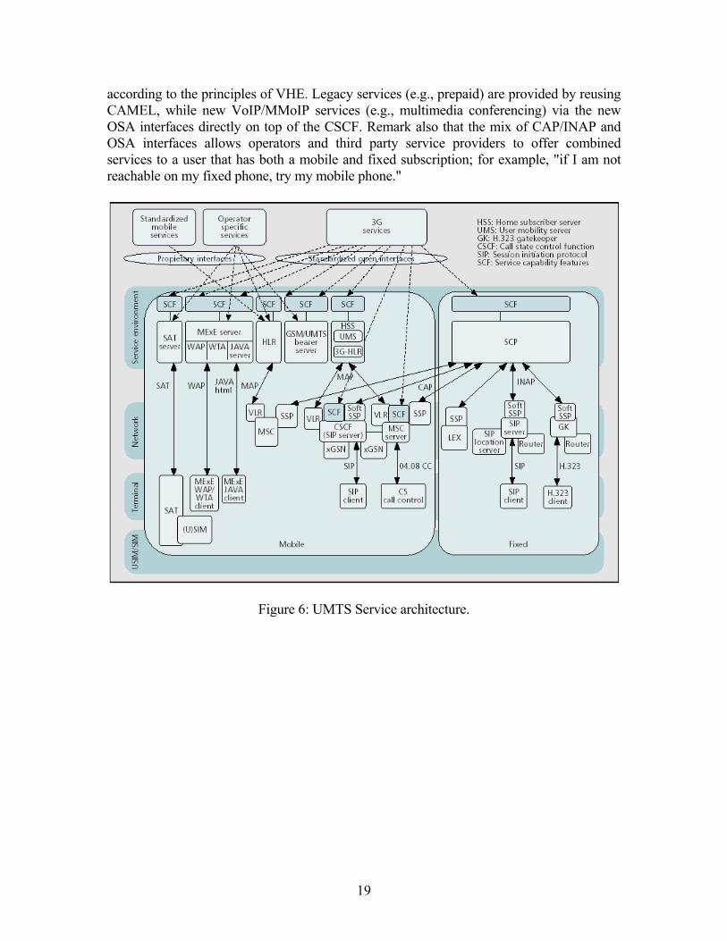
according to the principles of VHE. Legacy services (e.g., prepaid) are provided by reusing CAMEL, while new VoIP/MMoIP services (e.g., multimedia conferencing) via the new OSA interfaces directly on top of the CSCF. Remark also that the mix of CAP/INAP and OSA interfaces allows operators and third party service providers to offer combined services to a user that has both a mobile and fixed subscription; for example, "if I am not reachable on my fixed phone, try my mobile phone."
Figure 6: UMTS Service architecture.
19
TECHNIQUE OF MANAGEMENT OF USER
MOBILITY IN THIRD GENERATION ALL-IP NETWORKS
INTRODUCTION Mobile communication is transitioning toward third generation (3G) networks and beyond in order to provide high-speed data access and sophisticated services, predominantly based on IP. There are techniques in deploying several access technologies in a seamless converged IP-based network. For example, 3G cellular access, based on the code division multiple access technology (either wide band CDMA or cdma2000), may be used to support users who desire higher mobility over wider coverage areas, and broadband access based on the IEEE 802.11 specification to support users with relatively lower mobility over smaller geographical areas. The remaining challenge is the design of such a transport infrastructure that takes full advantage of IP-based technologies to achieve the desired mobility between the various access technologies, and at the same time provides the necessary capabilities in terms of quality of service (QoS), robustness, and manageability, to unleash the potential of emerging 3G services. Even though a number of proposals have been made recently for an IP-based architecture, what is quite often overlooked is the fact that the use of IP is not homogeneous throughout the different segments of the operator's network and the public Internet. We provide a taxonomy of the different ways in which IP/MPLS may be used in 3G networks, and identify how IP can be employed in the most beneficial manner. We then discuss the three levels of mobility support in the context of all-IP networks: access mobility, wide-area mobility, and micromobility. In particular, our focus is on the latter level, where we compare existing routing-based and tunneling-based techniques. Finally, we present an MPLS-based micromobility scheme that combines the advantages of hierarchical tunneling with those of MPLS transport. There are multiple reasons to use MPLS in the wireless infrastructure. First, MPLS is an efficient lightweight tunneling technology. Using MPLS tunnels, called label switched paths (LSPs) in MPLS jargon; an overlay network is efficiently created and managed. In MPLS, tunnel redirection, which is a crucial ingredient of any mobility scheme, happens quickly, at the change of a label in a single node in the network. Furthermore, by using this technology, we can directly take advantage of all the noted capabilities of MPLS in terms of QoS, traffic engineering, fast restoration, and support of advanced IP services, such as virtual private networks. The resulting MPLS-based mobility scheme fits the all-IP network model and simplifies the design of a converged seamless land network. The scheme uses an enhanced type of MPLS router called a label edge mobility agent (LEMA) that augments conventional MPLS operation with mobility-aware functionality. It allows for gradual deployment, since
20
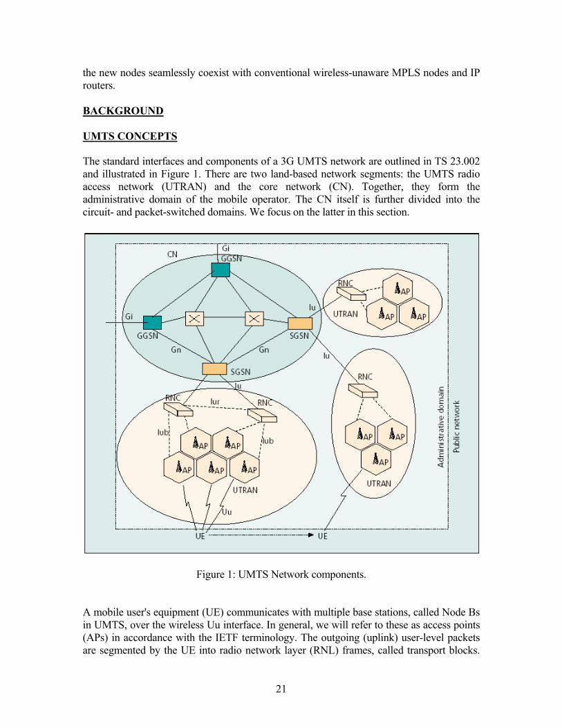
the new nodes seamlessly coexist with conventional wireless-unaware MPLS nodes and IP routers. BACKGROUND UMTS CONCEPTS The standard interfaces and components of a 3G UMTS network are outlined in TS 23.002 and illustrated in Figure 1. There are two land-based network segments: the UMTS radio access network (UTRAN) and the core network (CN). Together, they form the administrative domain of the mobile operator. The CN itself is further divided into the circuit- and packet-switched domains. We focus on the latter in this section.
Figure 1: UMTS Network components. A mobile user's equipment (UE) communicates with multiple base stations, called Node Bs in UMTS, over the wireless Uu interface. In general, we will refer to these as access points (APs) in accordance with the IETF terminology. The outgoing (uplink) user-level packets are segmented by the UE into radio network layer (RNL) frames, called transport blocks.
21
These are carried over the radio frequency layer, using the wideband CDMA (W-CDMA) access and modulation techniques, to the APs within reach of the mobile. Each AP encapsulates a set of transport blocks into a single frame of the RNL framing channels within protocol (FP) and forwards the frame to its radio network controller (RNC) over the Iub interface. The details of the sublayers of the RNL such as the packet data convergence protocol, radio link control, medium access control, and radio frequency layer are outlined in TS 25.401 and are not covered in the project. When the multiple APs serving a mobile host (or UE) have different controlling RNCs, one of the latter acts as the serving RNC for that host. The FP frames are exchanged between the controlling and serving RNCs over the Iur interface. The serving RNC of the host is responsible for frame selection among the multiple received copies of the same transport block, processing the other sublayers of the RNL, and finally reassembling the user-level packet. It also maintains the link layer state for the host, that is, it maps the host identity with the identities of the APs and the communication each AP that currently serves that host. The transport network between the APs and the RNCs has been traditionally composed of point-to-point E1/T1 lines. The packet-switched portion of the core network in UMTS consists of two types of Generalized Packet Radio Service (GPRS) support nodes (GSNs), the serving GPRS support node (SGSN) and the gateway GPRS support node (GGSN). In order to communicate with the data network, the mobile host needs to register with the CN by performing a GPRS attach operation. This results in the creation of two GPRS tunneling protocol (GTP) sessions, specific to that host: between the RNC and the SGSN on the Iu interface, and between the SGSN and the GGSN on the Gn interface. The user-level packets are encapsulated into GTP frames and are forwarded between the RNC and the GGSN over a chosen transport network. Traditionally, this network has been based on ATM. Upon GPRS attachment, a mapping is created at the RNC between the host identity and the GTP session between the RNC and the SGSN. In addition, a record is created at the GGSN, which contains the mapping between the host's network layer (IP) address and the GTP session with the corresponding SGSN. The SGSN handles the inter-RNC mobility of the host, while the GGSN handles the inter-SGSN mobility. When the serving RNC of the mobile changes, as long as the new RNC is within the scope of the same SGSN, it results in the re-direction of the GTP session between the SGSN and the RNC. The session between the SGSN and GGSN remains unaffected. On the other hand, if mobility results in a different point of GPRS attachment (i.e., a different SGSN), both host-specific GTP sessions are reestablished. In addition to mobility management the GSNs also perform various accounting and security functions that do not affect the underlying network architecture.
22

DEPLOYMENT OF IP AND MPLS There are two primary modes in which IP may be deployed in a segment of a mobile network. In the first case, the destination IP address of an end-user packet is not used to make the packet forwarding decision. Instead, the packets are encapsulated in an intermediate layer (e.g., FP on the Iub interface and GTP in the CN), which may be specific to the chosen wireless technology. The encapsulated data units are then transported, between the nodes in the segment, over another IP layer. Most of the existing proposals espouse this approach, which allows the mobile operator to keep many of the legacy components of the 2G network untouched while upgrading just the transport layer from point-to-point lines or an ATM network to an IP-based network. We refer to this case as the transport mode of IP deployment. Alternatively, the end user's IP packet may undergo regular IP forwarding based on the destination address, without involving other intermediate layers. This case corresponds to deployment of IP in the native mode. Obviously, the absence of intermediate protocol layers inherently implies a higher efficiency. Furthermore, segments of a mobile network that employ this mode do not require nodes specific to any wireless technology, and hence can be used by the operator to support heterogeneous access networks. Therefore, it is beneficial to have the largest portion of an all-IP mobile network implement IP in the native mode. Furthermore, MPLS is a technology which, when used in conjunction with IP, substitutes conventional IP address lookup and forwarding within a network with the faster operations of label lookup and switching. In an IP/MPLS-based segment, the IP header is analyzed only at the entry and exit points of the segment. At the entry point, the packet is assigned to a specific forwarding equivalence class (FEC), and the FEC is encoded into the packet's extended header as a short fixed-length label. At the subsequent hops within the segment, no IP header analysis is performed; instead, the label is used as an index into a lookup table that specifies the next hop and the new label value. The next hop assignment for a particular FEC is either determined by running conventional routing protocols or statically engineered. The path taken by a packet belonging to a FEC inside the MPLS segment is referred to as the LSP for that FEC. The internal nodes that perform MPLS switching are called label-witching routers (LSRs), while the routers located at the boundaries are usually referred to as label edge routers (LERs). In addition to fast forwarding, MPLS provides other significant advantages. LSPs can be either signaled or engineered to provide QoS guarantees. Traffic engineered LSPs can be provided with restoration paths for reliability, while LSPs constructed using link state information are automatically re-configured whenever the state is refreshed. Moreover, the framework for signaling, traffic engineering, QoS, restoration, and virtual private networks is already available for MPLS networks and being actively deployed. Service providers are gradually migrating toward this framework by creating islands of MPLS transport within the IP-routed network. Because of its added benefits, we adopt MPLS as the layer below IP in the all-IP network models presented in this article.
23

3G ALL-IP NETWORK MODELS IP/MPLS: TRANSPORT MODE The 3GPP specifications leave the transport layer implementation open. Accordingly, IP/MPLS may be used for transport in the UTRAN as well as in the CN shown in Figure 1. The corresponding illustrative protocol stack is shown in Fig. 2.
Figure 2: All-IP options protocol stacks: IP/MPLS transport mode To deploy this mode on the Iub interface, the FP frames are encapsulated into IP packets. In the uplink direction, the destination address of the packet is fixed and refers to the controlling RNC, and in the downlink direction, the address belongs to the AP(s) currently serving the given host. The determination of the serving AP(s) is made by the RNC using the maintained link layer state for all the currently served hosts. The Mobile Wireless Internet Forum (MWIF) has specified further details concerning the implementation of IP in the UTRAN in the transport mode, along with the techniques for multiplexing several FP frames into the same IP packet. Summarily, the host's IP address is never used for forwarding purposes in the UTRAN, the decisions being made on the basis of RNL- specific protocols. To deploy MPLS, LSPs are preconfigured between the APs and the RNCs. In a similar manner, on the Iu and Gn interfaces of the core network, the GTP frames are encapsulated into IP packets. The destination address of these packets refers to the network components (i.e., the RNC, SGSN, or GGSN) and not the user's IP address. Forwarding decisions are based on the GTP mapping tables in those nodes. For MPLS forwarding, LSPs are preconfigured by the network operator between the RNCs, SGSNs, and GGSN.
24

IP/MPLS: NATIVE MODE There have been a few proposals for using native mode IP forwarding in the CNs of the network operator's administrative domain. Referring specifically to UMTS, in TR 23.922, an integrated GSN (IGSN) is introduced, which combines the functions of the SGSN and GGSN, and directly communicates with the RNC. Except for the Iu interface, where GTP over IP in the transport mode is retained, the rest of the CN uses regular IP forwarding based on the end-user's IP address. The protocol stack for this mode of operation is shown in Fig. 3. A similar all-IP architecture is proposed in the context of cdma2000 networks.
Figure 3: All-IP options protocol stacks: IP/MPLS native mode (with IGSN). Our vision for an IP/MPLS enabled CN that only uses native mode forwarding is shown in Fig. 3. We introduce a new node, called a 3G-access router (AR), in which an IGSN function is collocated with a UMTS radio network controller. There are no topological restrictions on the placement of 3G ARs in the network. At one extreme, an operator may replace a number of existing RNCs and GSNs by a single 3G AR. On the other hand, a more distributed approach may be followed by replacing a single existing RNC with a 3G AR, and regular routers in place of the existing GSNs. The RNC function within the 3G AR operates in the same fashion as described before. FP frames are transported to and from the APs over an IP/MPLS network in the transport mode. Conceivably, the native mode coverage of IP can be extended into the UTRAN by implementing an access router with collocated Node B, RNC, and IGSN functions. Some equipment vendors are adopting this approach by building what are known as intelligent base stations with varying combined functionalities. The IGSN function within the 3G AR provides all the UMTS-specific accounting and security features. The rest of the CN consists of regular routers and switches that forward packets on the basis of the user-level IP addresses. One or more border routers provide the gateway to the public Internet. In order to deploy MPLS in the domain, all the ARs and a chosen number of routers in the domain function as LERs. LSPs may be signaled or statically engineered between the LERs on the basis of their supported IP address ranges for reachability, QoS requirements, or a
25
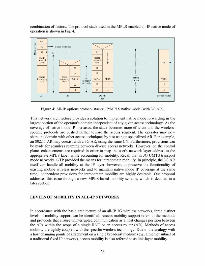
combination of factors. The protocol stack used in the MPLS-enabled all-IP native mode of operation is shown in Fig. 4.
Figure 4: All-IP options protocol stacks: IP/MPLS native mode (with 3G AR). This network architecture provides a solution to implement native mode forwarding in the largest portion of the operator's domain independent of any given access technology. As the coverage of native mode IP increases, the stack becomes more efficient and the wireless-specific protocols are pushed farther toward the access segment. The operator may now share the domain with other access techniques by just using a specialized AR. For example, an 802.11 AR may coexist with a 3G AR, using the same CN. Furthermore, provisions can be made for seamless roaming between diverse access networks. However, on the control plane, enhancements are required in order to map the user's network layer address to the appropriate MPLS label, while accounting for mobility. Recall that in 3G UMTS transport mode networks, GTP provided the means for intradomain mobility. In principle, the 3G AR itself can handle all mobility at the IP layer; however, to preserve the functionality of existing mobile wireless networks and to maintain native mode IP coverage at the same time, independent provisions for intradomain mobility are highly desirable. Our proposal addresses this issue through a new MPLS-based mobility scheme, which is detailed in a later section. LEVELS OF MOBILITY IN ALL-IP NETWORKS In accordance with the basic architecture of an all-IP 3G wireless networks, three distinct levels of mobility support can be identified. Access mobility support refers to the methods and protocols that ensure uninterrupted communication as a host changes position between the APs within the scope of a single RNC or an access router (AR). Methods of access mobility are tightly coupled with the specific wireless technology. Due to the analogy with a host changing points of attachment on a single broadcast medium (e.g., Ethernet subnet of a traditional fixed IP network), access mobility is also referred to as link-layer mobility.
26
An IP-enabled mobile host communicates with the rest of world via a globally reachable CN node. This is a GGSN in the scenario of Figure 2, an IGSN in Figure 3, and a 3G AR in Figure 4. Changing position between different such nodes requires wide-area mobility support. Traditionally, wide-area mobility has been based on the family of Mobile IP (MIP) protocols. MIP employs the concepts of home agent (HA), foreign agent (FA), and care-of address (CoA). When away from its home network a mobile host obtains a temporary IP address, a CoA, which belongs to the visited network and is routable from elsewhere. The CoA may be assigned to an interface of a mobile host itself (collocated CoA) or offered by a local router (e.g., the AR). Such a router serves as an FA for that host, and the CoA thus obtained is referred to as an FA CoA. The host registers its CoA with a specific router on its home network designated as its HA. Registration (i.e., knowledge of the mobile's CoA) enables the HA to intercept IP packets addressed to that host, encapsulate them using an outer IP header with the destination address set to the registered CoA, and route them using regular IP forwarding. In effect, a tunnel is established through the network to the mobile host's current location. In the proposed all-IP network model, it is possible to extend the scope of wide-area mobility by applying Mobile IP all the way to the AR. However, this may significantly increase the overhead and impair scalability as the number of mobile users grows. Any change in the host's CoA necessitates an HA re-registration. The closer the endpoint of the MIP tunnel to the host, the more often-such changes would occur. Since the home network (and therefore the HA) may be located quite remotely in geographical terms, the amount of signaling traffic may create a substantial burden and cause excessive latency in mobility support. Therefore, it is important that an additional lightweight mechanism be implemented that can handle the host movement between ARs locally, without generating HA traffic. This mechanism is referred to as micromobility. In the GPRS and UMTS scenario (Figure 2,3,4), micromobility is managed by means of GTP session redirection. However, this approach is tied to a specific wireless technology, and does not allow for native mode IP forwarding. MOBILE IP VARIANTS The base version of Mobile IP, originally proposed in the context of IPv4, suffers from several drawbacks. Above all, the path a packet takes on its route to a mobile host is clearly non optimal. The packet needs to first reach the HA, and only then is it tunneled to the final destination -- a phenomenon known as triangular routing. A set of routing optimization extensions has been proposed to address this issue. These extensions allow the HA to be bypassed on the downstream (i.e., toward the mobile host) transmission path. This is achieved by providing a means for the corresponding nodes to cache the address binding information of the mobile hosts and tunnel the packets directly to their CoAs. Another problem is associated with the requirement that a host has to use its home address as the source address in the packet header. For a visiting mobile, this address is topologically incorrect, which may cause the packet to be dropped at any point in a network that implements security functions, such as ingress filtering or firewalls. The reverse tunneling
27
option eliminates the latter problem at the expense of yet another overhead routing path: an outgoing packet is encapsulated and tunneled by the FA or mobile host to the HA. Mobility support in IPv6 is implemented as an integral part of the underlying IP layer through the use of destination options: Binding Update, Binding Acknowledgment, Binding Request, and Home Address. While the concepts of HA, home address, and CoA are retained, the neighbor discovery feature of IPv6 allows a mobile host to operate without explicit support of an FA. The problem of triangular routing is eliminated by making provisions for binding updates to be delivered directly to the corresponding nodes. The source address in the header of an outbound packet is set to the mobile node's CoA, thus making it compliant with the source address filtering routers. In addition, the use of the IPv6 routing header reduces the overhead of encapsulation. While MIPv6 effectively eliminates many of the shortcomings of MIPv4, both these protocols are oriented toward wide-area network mobility management, or macromobility. Every time a host moves beyond the limits of link layer connectivity, a registration or binding update message needs to propagate all the way to the host's HA. When the node moves within a relatively small geographic area remotely located with respect to its home network, this may lead to large overhead and suboptimal performance. Enhancing the base IP mobility management protocols with scalable capabilities that reduce latency, packet loss, and signaling overhead during handoffs has been a subject of extensive discussions within the IETF Mobile IP working group. MICROMOBILITY REQUIREMENTS There are two types of addresses associated with a mobile host: its identifying address (e.g., the MIP static home address) that uniquely distinguishes the host from its peers, and the routable address that is used to reach the mobile from elsewhere in the network (e.g., the temporary CoA). In the proposed network architecture (Figure 5), an AR maintains the link layer state for each mobile host in its scope. However, the AR is not required to supply routable addresses to its hosts. Instead, a routable address may be associated with any node in the CN segment. Such a node has to maintain the mapping between the identifying address of the mobile host and the CN reachability information (e.g., the destination AR). When the host moves between the scopes of different ARs, it is only this mapping that has to change, whereas the routable address can remain the same. Formally, we apply the term micromobility to any host movement outside the scope of a single AR that does not require a change of its routable address. We shall refer to a CN node that supports micromobility as a mobility agent. Conceptually, a mobility agent is a router that has to be able to maintain a forwarding lookup table composed of two sections. The first part is built and updated by conventional routing protocols. The second part contains identifying addresses of the known mobile hosts and is maintained by mobility-specific signaling mechanisms. The latter section of the forwarding lookup table is necessarily flat, that is, no topological grouping of network addresses can be applied to decrease its size.
28
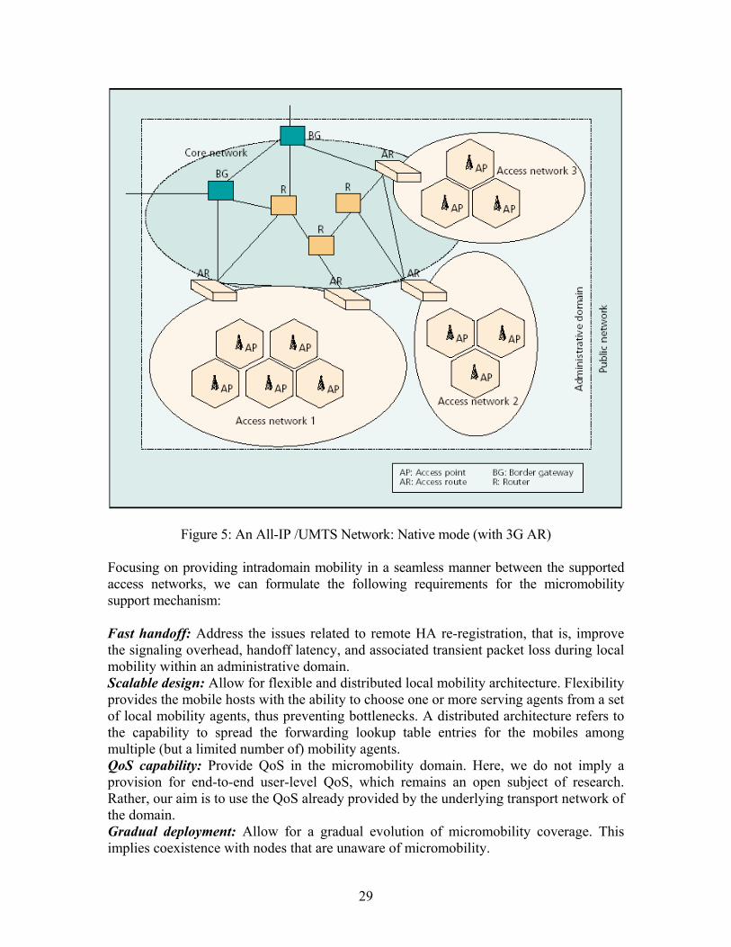
Figure 5: An All-IP /UMTS Network: Native mode (with 3G AR) Focusing on providing intradomain mobility in a seamless manner between the supported access networks, we can formulate the following requirements for the micromobility support mechanism: Fast handoff: Address the issues related to remote HA re-registration, that is, improve the signaling overhead, handoff latency, and associated transient packet loss during local mobility within an administrative domain. Scalable design: Allow for flexible and distributed local mobility architecture. Flexibility provides the mobile hosts with the ability to choose one or more serving agents from a set of local mobility agents, thus preventing bottlenecks. A distributed architecture refers to the capability to spread the forwarding lookup table entries for the mobiles among multiple (but a limited number of) mobility agents. QoS capability: Provide QoS in the micromobility domain. Here, we do not imply a provision for end-to-end user-level QoS, which remains an open subject of research. Rather, our aim is to use the QoS already provided by the underlying transport network of the domain. Gradual deployment: Allow for a gradual evolution of micromobility coverage. This implies coexistence with nodes that are unaware of micromobility.
29
MICROMOBILITY PROTOCOL OVERVIEW Existing proposals for micromobility can be broadly classified into two types: routing-based and tunnel-based schemes. Routing-based schemes aim to exploit the robustness of conventional IP forwarding. A distributed mobile host location database is created and maintained within the network domain. The database consists of individual flat mobile-specific address lookup tables and is maintained by all the mobility agents within the domain. These schemes are exemplified by the Cellular IP and Hawaii protocols, which differ from each other in the functionality of the nodes and the construction methods of the lookup tables. In one form or another, the tunnel-based schemes apply the concepts of registration and encapsulation in a local or hierarchical fashion, thus creating a flexible concatenation of (possibly several) local tunnels. In the context of MIPv4, the Mobile IP regional registration proposal falls into this category. Hierarchical Mobile IP plays a similar role in IPv6 networks. An early example of a tunnel-based scheme is provided by GTP-based mobility management in GPRS and UMTS. ROUTING-BASED SCHEMES Hawaii -- In this proposal, the micromobility domain is composed of Hawaii-enabled IP routers. The gateway into the domain, which handles all inbound and outbound mobile traffic, is referred to as the domain root router. When a mobile host powers up within a domain, it is dynamically assigned an IP address. Outside the domain, this address is routed toward the domain root, while within the domain it is used for identification purposes only. If the mobile host is visiting a foreign domain, this address is used as a MIP CoA. Forwarding entries for mobile hosts are created and maintained using explicit signaling messages (e.g., MIP Registration message) initiated by the hosts. When a host transmits such a message on power-up or change of location, it is relayed, along the optimal path, to the domain root in the form of a Hawaii signaling message. All routers receiving this message establish and update mobile-specific entries for the reverse path packet forwarding. Several path setup schemes are defined, which may additionally allow, in the case of handoff, the routers on the former downlink path to be notified to forward (transient) incoming packets to the new location of the mobile node. The domain root necessarily maintains a flat address lookup table with forwarding metrics for all active mobile hosts in its domain, while each routing node is required to maintain a part of this table. Cellular IP -- The Cellular IP proposal adopts a similar approach to mobility management based on a rooted domain, but uses a different signaling technique. Instead of sending and processing explicit messages, the nodes have an ability to learn the source IP addresses of uplink data packets and map them to the corresponding downlink
30

interfaces. The uplink path (i.e., the direction toward the domain root), or gateway, is inferred by each AP/AR within the domain using the beacon packets periodically transmitted by the gateway. All the packets generated by the mobile hosts are forwarded toward the gateway using this uplink path. In addition, to refresh its forwarding cache entries, a host may explicitly transmit uplink route update packets. Two handoff schemes are supported. Hard handoff allows some packet loss while being efficient in the amount of signaling overhead and latency. Semi-soft handoff aims to minimize the transient packet loss, while exploiting the capability of a mobile to receive packets from both old and new APs. Similar to the Hawaii case, the forwarding cache of the gateway contains entries for all active mobiles in the domain. TUNNEL-BASED SCHEMES Regional Registration --The regional registration extension to MIPv4 defines a tree- like hierarchy of FAs with a special entity called a gateway FA (GFA) residing at the root of the tree. Several levels of regional FAs (RFAs) can be supported between the GFA and local FAs. The lowest-level FA advertises the entire FA/RFA/GFA hierarchy. When a mobile host first arrives in a visited domain, it performs a registration with its HA using the IP address of the GFA as its care-of (routable) address. Subsequently, when it changes location within the visited domain under the same GFA, only a regional registration is required. The host may perform regional registration with the GFA or any lower-level RFA, as inferred from the agent advertisement messages. In either case, the regional registration request is relayed up the FA hierarchy, appropriately changing the visitor list entries (i.e., local CoAs) at each level. Along with the capability to perform a regional registration with the advertised GFA, the host has the flexibility to designate any intermediate level RFA as a GFA, and to provide the routable address for HA registration. Alternatively, the host may bypass regional registration altogether and may obtain its routable address using the lowest-level FA, in conventional MIPv4 fashion. Hierarchical Mobile IPv6 -- While FAs are not defined in the context of MIPv6; micromobility support requires a local entity to assist with handoffs. Such an entity acts as a local HA providing registration capabilities to the associated hosts. The Hierarchical Mobile IPv6 proposal introduces a mobility anchor point (MAP) to perform this function. Upon arrival in a visited network, a mobile host discovers the addresses of the existing MAPs and their respective distances via router advertisement messages. It then configures two care-of addresses: an on-link CoA (LCoA), which is a routable address based on the prefix advertised by the mobile's default router, and a regional CoA (RCoA), which is either an address on the MAP subnet (basic mode of operation), or the address of one of the MAP's interfaces (extended mode). The host then registers with its HA, creating a binding between its home address and the RCoA. It also sends a binding update to the MAP to register the binding between the RCoA and the LCoA. In the basic mode, the MAP acts exactly as a local HA, intercepting all packets addressed to the RCoA, encapsulating and tunneling them to the LCoA. The mobile host decapsulates and processes the packets in the regular fashion. In the extended mode, the MAP decapsulates
31
inbound packets and makes the forwarding decision based on the inner header. If the destination address of the inner packet belongs to its registered mobile (and is stored in the binding cache), the MAP tunnels the packet to the LCoA. The HMIPv6 proposal provides for multiple MAPs within the visited domain, which can be arranged either to handle different subsets of corresponding nodes, or in a hierarchical fashion, for example, to provide support to mobile routers that can act as MAPs themselves. While routing-based schemes avoid the tunneling overhead, they face difficulties in scaling, since for each mobile the forwarding table entries have to be replicated in all nodes on the uplink path, as opposed to selected nodes as in tunnel-based schemes. This also means that gradual deployment of routing-based mobility support can be difficult. Furthermore, the root (gateway) node of routing-based schemes constitutes a single point of failure. On the contrary, in the tunnel-based schemes, it is possible to designate multiple GFAs or MAPs within the micromobility domain, thus achieving higher robustness. All these factors, along with the ability to employ lightweight tunnels, explain why hierarchical tunnels seem to emerge as a preferred solution for supporting micromobility in all-IP wireless networks. MPLS-BASED MICROMOBILITY Our proposal for micromobility is based on MPLS, and overcomes most of the limitations of the existing schemes in addressing the specified micromobility requirements. We apply the principles of the earlier work on tunnel-based schemes, specifically HMIPv6, to a network that employs MPLS. The choice of handling mobility at the MPLS layer is a natural one in the MPLS-enabled all-IP network architecture, and does not impose any additional protocol overhead. There is some previous work on MPLS-based mobility. However, the focus so far has been on integrating MIP with MPLS while retaining the transport mode of operation. THE OVERLAY LEMA NETWORK We define a label edge mobility agent (LEMA) as a function that has the following capabilities. First, it functions as a standard LER and maps the destination IP address of a packet into a FEC. The FEC itself is associated with a tuple containing the next hop identity and the outgoing MPLS label, and hence identifies a specific LSP. Second, for a given IP address it creates a new mapping to a FEC in response to a local registration message. Finally, it updates an existing mapping of an IP address in response to a redirect message.
32
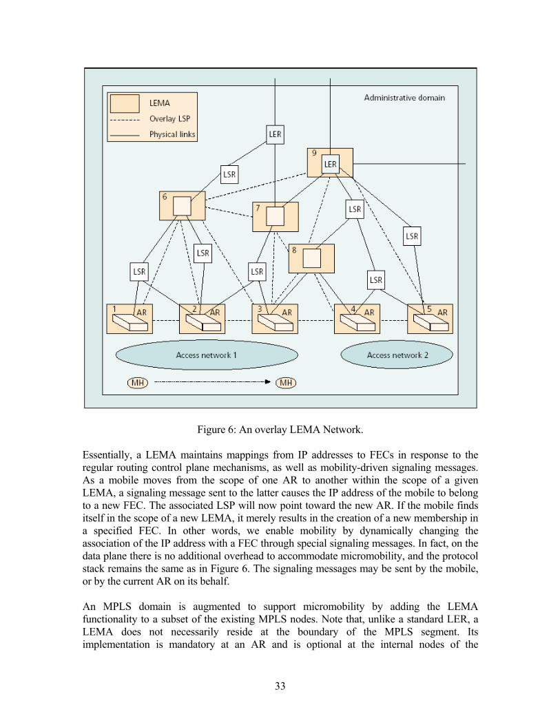
Figure 6: An overlay LEMA Network. Essentially, a LEMA maintains mappings from IP addresses to FECs in response to the regular routing control plane mechanisms, as well as mobility-driven signaling messages. As a mobile moves from the scope of one AR to another within the scope of a given LEMA, a signaling message sent to the latter causes the IP address of the mobile to belong to a new FEC. The associated LSP will now point toward the new AR. If the mobile finds itself in the scope of a new LEMA, it merely results in the creation of a new membership in a specified FEC. In other words, we enable mobility by dynamically changing the association of the IP address with a FEC through special signaling messages. In fact, on the data plane there is no additional overhead to accommodate micromobility, and the protocol stack remains the same as in Figure 6. The signaling messages may be sent by the mobile, or by the current AR on its behalf. An MPLS domain is augmented to support micromobility by adding the LEMA functionality to a subset of the existing MPLS nodes. Note that, unlike a standard LER, a LEMA does not necessarily reside at the boundary of the MPLS segment. Its implementation is mandatory at an AR and is optional at the internal nodes of the
33

administrative domain. Figure 6 shows a domain augmented with LEMAs. The LEMA nodes form an overlay network whose edges are pre-established LSPs, which may be traffic engineered if necessary. A LEMA-to-LEMA LSP may correspond to a concatenation of several physical links and regular intermediate LSRs. Also, with respect to a transit LSP, the LEMA node itself functions as a standard LSR. To support traffic of multiple QoS classes, several LSPs may be provisioned between pairs of LEMAs. Upgrading the network involves adding LEMA management software to a selected set of MPLS nodes. (MPLS nodes already provide the ability to do FEC mapping and forwarding based on classification.) The LEMA software is responsible for processing the mobility-related signaling messages and dynamically changing the membership of a host's IP address in a FEC. In addition, the LEMA signaling software has to be added to the mobile hosts that are enabled with micromobility. Since a LEMA allows a mobility-driven change to the FEC associated with a specified IP address, it provides the service of a local HA to the mobile host. Any host whose IP address does not topologically match the subnet addresses supported by the current AR may avail itself of this service in addition to using wide-area mobility. To facilitate this, the AR advertises the addresses of a subset of reachable LEMAs as well as information on how they are arranged. The host chooses to register with one or more of the advertised agents to create its own chain of hierarchical local HAs. Registering at a given level results in a mapping of the host's IP address to an LSP that points to the agent at the next lower level. For a given host, the lowest-level LEMA does the access point mapping, while the highest-level LEMA at which it is registered provides its routable address (CoA) for wide-area mobility. The algorithm an AR uses to choose the subset of reachable LEMAs to advertise at any given point in time is orthogonal to the mobility architecture. For example, it may use the LSPs that are least utilized in order to make the choice. Alternatively, the advertisements may merely reflect the static overlay topology of the LEMAs. Similarly, the algorithm the mobile uses to decide with which LEMA(s) to register is also beyond the current scope. As an example, the host's mobility patterns may be used to make this decision. A host with limited movement may register only with the lowest advertised LEMA, while a host with unpredictable mobility patterns may register with LEMAs at many levels of the advertised hierarchy to cover the geographical area of movement. Note that the hierarchy of LEMAs with which a host registers is not imposed by the hierarchical structure of the overlay LEMA network. One of the key differentiating factors of this scheme from other hierarchical mobility schemes is that each mobile has the flexibility to create its own chain. For example, referring to Figure 6, as the mobile moves from AR 1 to AR 3, it first registers only with LEMA 1. As it moves within the scope of AR 2, it registers with the chain (2, 6, 9) with node 9 serving as a MIPv4 FA. Movement from AR 2 to AR 3 results in a single change in the chain to (3, 6, 9). Any change in the top-level LEMA, in this case from 1 to 9, also requires a MIP re-registration with the host's HA. In the trivial case, a visiting mobile is only registered with its own AR, which continues to provide the routable address, and micromobility is not used. In general, the highest-level registered LEMA for a given mobile host defines the micromobility boundary for that host.
34

Since the destination IP address of the host is not locally routable in the micromobility domain, each of the LEMAs at which the host is registered needs to keep a forwarding entry for that mobile. It is this entry that maps the network layer address to the corresponding MPLS label, or the overlay LSP. Note, however, that the other LEMAs in the domain as well as the other LSRs do not have any forwarding entry specific to this mobile. In other words, the flat address lookup tables are implemented only at the LEMAs, and moreover, a forwarding entry for a host exists only at those LEMAs at which that host is registered. This significantly improves the scalability of this scheme with respect to the existing routing-based proposals. REGISTRATION AND HANDOFF PROCEDURES Here, we illustrate the operations associated with registration and handoff using a simple example. We again refer to the overlay network shown in Figure 6. When the mobile host moves within the scope of AR 1, it first completes the link layer attachment, which results in the access point mapping for the host at the AR. The AR periodically sends advertisement messages containing the subset of reachable LEMAs and their topological layout. The host receives an advertisement containing the subtree (1, (6, (7, 9))) rooted at the AR itself. After running its selection algorithm, the host chooses the chain (1, 6) for registration. It registers its identifying address (say, its static IP address) with LEMA 1. Furthermore, it registers with LEMA 6 by specifying the address of LEMA 1 along with its own identifying address, in order to indicate the chosen LSP (from 6 to 1). On receipt of this message, LEMA 6 maps the identifying address of the host to the FEC that corresponds to that LSP. In addition to the local registration, a MIP home agent registration is performed using the routable address provided by LEMA 6. When the host moves from the scope of AR 1 to that of AR 2, it receives a new advertisement message from the latter containing the subtree (2, (6, (7, 9))). The host recognizes that a handoff has to be initiated by comparing its current chain (1, 6) with the new subtree. Essentially, it traverses down the subtree and the current chain one node at a time till it finds a matching LEMA. In our example it finds a previously registered LEMA 6. After running the selection algorithm again, it creates a new chain (2, 6). It registers its identifying address with LEMA 2 and issues a redirect message to LEMA 6 in order to change its mapping to the LSP that points to LEMA 2. In general, traversing the recomputed chain, a new registration message has to be sent to all the LEMAs that have changed with respect to the previous chain, and a redirect message has to be sent to the first matching LEMA if the latter exists. In this case, no MIP HA reregistration is necessary. Additionally, a redirect message is also sent to the previously registered LEMAs so that the packets in transit during the change in registration may be forwarded to the new AR. Accordingly, in this example, LEMA 1 is notified to change its mapping for the host's identifying address to the FEC that corresponds to the LSP from AR 1 to AR 2. Next, as the host moves to the scope of AR 3 and completes the link layer attachment, it
35
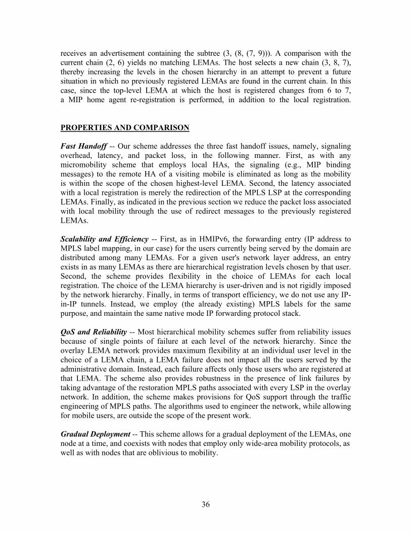
receives an advertisement containing the subtree (3, (8, (7, 9))). A comparison with the current chain (2, 6) yields no matching LEMAs. The host selects a new chain (3, 8, 7), thereby increasing the levels in the chosen hierarchy in an attempt to prevent a future situation in which no previously registered LEMAs are found in the current chain. In this case, since the top-level LEMA at which the host is registered changes from 6 to 7, a MIP home agent re-registration is performed, in addition to the local registration. PROPERTIES AND COMPARISON Fast Handoff -- Our scheme addresses the three fast handoff issues, namely, signaling overhead, latency, and packet loss, in the following manner. First, as with any micromobility scheme that employs local HAs, the signaling (e.g., MIP binding messages) to the remote HA of a visiting mobile is eliminated as long as the mobility is within the scope of the chosen highest-level LEMA. Second, the latency associated with a local registration is merely the redirection of the MPLS LSP at the corresponding LEMAs. Finally, as indicated in the previous section we reduce the packet loss associated with local mobility through the use of redirect messages to the previously registered LEMAs. Scalability and Efficiency -- First, as in HMIPv6, the forwarding entry (IP address to MPLS label mapping, in our case) for the users currently being served by the domain are distributed among many LEMAs. For a given user's network layer address, an entry exists in as many LEMAs as there are hierarchical registration levels chosen by that user. Second, the scheme provides flexibility in the choice of LEMAs for each local registration. The choice of the LEMA hierarchy is user-driven and is not rigidly imposed by the network hierarchy. Finally, in terms of transport efficiency, we do not use any IP-in-IP tunnels. Instead, we employ (the already existing) MPLS labels for the same purpose, and maintain the same native mode IP forwarding protocol stack. QoS and Reliability -- Most hierarchical mobility schemes suffer from reliability issues because of single points of failure at each level of the network hierarchy. Since the overlay LEMA network provides maximum flexibility at an individual user level in the choice of a LEMA chain, a LEMA failure does not impact all the users served by the administrative domain. Instead, each failure affects only those users who are registered at that LEMA. The scheme also provides robustness in the presence of link failures by taking advantage of the restoration MPLS paths associated with every LSP in the overlay network. In addition, the scheme makes provisions for QoS support through the traffic engineering of MPLS paths. The algorithms used to engineer the network, while allowing for mobile users, are outside the scope of the present work. Gradual Deployment -- This scheme allows for a gradual deployment of the LEMAs, one node at a time, and coexists with nodes that employ only wide-area mobility protocols, as well as with nodes that are oblivious to mobility.
36

SATELLITE BASED UMTS IP NETWORK: SATIN INTRODUCTION Second generation mobile satellite systems failed to grab the mobile market (e.g.; IRIDIUM), raising a lot of concerns about the future of commercial satellite systems in general. However the multimedia concept, strongly embedded within UMTS, introduced a new perspective for the mobile satellite systems as collaborative parts of terrestrial UMTS (T-UMTS) rather than stand-alone systems.
The satellite component of the UMTS (S-UMTS) system architecture has been extensively studied in a number of projects run over the last five years (such as EU ACTS projects SUMO and SINUS) and some basic principles have been established. The requirement for interoperability and integration with T-UMTS was one of the main drivers of these studies while the concept of discriminating between radio-independent and radio-dependent functions in the system design, as it was first coined in the RAINBOW project for T-UMTS, seems to have achieved wide acceptance
However recent developments in the T-UMTS architecture generate some new challenges for the S-UMTS architecture design. The introduction of packet-mode into the system definition and the ever-increasing penetration of the Internet Protocol (IP) into the system functions constitute the basic reasons for a re-examination of the system architectures proposed so far and their modification/optimisation.
SATIN (Satellite-UMTS IP-based Network) is an IST research and technology project. Its main objective is to introduce a new packet-based S-UMTS architecture as an integral part of UMTS. The derivation of specifications for the access scheme in packet mode, including functions and respective component interfaces, as well as the evaluation of key issues by means of simulation are tasks stemming from this objective.
The section is organized as follows: The current penetration of IP into the T-UMTS is first reviewed and the future trends regarding the level of this penetration are presented. After a brief description of the architectures envisaged within SATIN, the corresponding requirements for the S-UMTS air interface are investigated. Different options are identified depending on the IP penetration into the Core Network (CN). The paper concludes by outlining the approach taken in SATIN.
37

T-UMTS AND IP Internet is considered to be one of the big success stories in the telecommunications and computer world. IP traffic is without doubt the dominant type of traffic in current data networks. More recently IP has been gaining acceptance as a platform for delivery of multimedia services. In fact IP is the protocol of today and seems more than ever before to be the protocol of the future as well.
UMTS (3G systems in general) have their vision to marry two success stories: cellular mobile networks and the Internet. IP is certainly present in the first release of T-UMTS (Release '99). IP is deployed for transport of both data and signalling in the Core UMTS Network over the GTP tunnels, while IP addresses are allocated statically or dynamically to mobile hosts. However the level of this presence is limited so that we talk about interworking of the two technologies (Internet and cellular) rather than real integration.
Since mid-1999, UMTS specification work has been driven by a shift towards an all-IP UMTS network architecture. This shift formed the basis for the R00 specifications, which replaced the circuit-switched transport technologies used in UMTS R99 by packet switched and introduced multimedia support in the UMTS core network.
Mobile-IP, Session Initiation protocol (SIP), IP Integrated and Differentiated services are components of the IP ensemble envisaged for introduction in UMTS subsequent releases. The level of IP penetration into the UMTS architecture is constantly increasing, modifying the way certain system functions are implemented. In the following, the IP role in a number of UMTS functions is briefly reviewed, in an attempt to identify the terrestrial network that SATIN has to interface with.
Mobility Regarding UMTS we can distinguish two different types (levels) of mobility:
• Macro-mobility: namely mobility between different RNC/SGSN nodes. • Micro-mobility: namely mobility between different Node B elements within the
same radio Access Network (RAN) - controlled by the same RNC.
In UMTS release '99, macro-mobility is treated by the Core Network nodes/entities, SGSN, GGSN and HLR/VLR, assisted by the GTP protocol running over the Iu and Gp/Gn interfaces (Figure 1). GTP tunnels are set-up and released when the mobile is moving, making sure that user and signaling data are routed via the appropriate 3G-GSN. The basic idea is to replace the GPRS core network with an UTRAN-IP gateway that will terminate the Non Access Stratum signaling on the fixed network side and charge Mobile IP and its enhancements with the task of macro-mobility management.
38

Regarding micro-mobility, a number of IP-based schemes have been proposed for supporting mobility within the RAN (e.g. Hawaii, Cellular IP, etc) and have been dealt in the section on mobility. These solutions assume IP transport in the RAN and aim at replacing the standard UMTS mechanisms (soft handoff). However there are a lot of objections in relation to the applicability of these proposals in the UMTS case. The main obstacles are:
• The specific characteristics of the UMTS RAN radio network, namely the strict delay requirements for soft handoff, the absence of an end-to-end IP routing model and IP transport within the RAN, the radio-specific layers of the nodes. The same reasons also render inappropriate the use of application-level solutions to the micromobility problem
• The lack of mature IP-based mechanisms that could, even in the case some of above constraints are overcome, provide a more efficient mobility mechanism than the specialized one currently deployed.
Figure 1: 3G Satellite UMTS Architecture.
IP TRANSPORT IN THE RAN In release '99 the transport of both data and signaling is provided by ATM/AAL2. There are quite strict requirements in terms of delay and transport efficiency that rendered IP suitability questionable. The lack of a mature QoS framework and the overhead imposed by the associated headers were the two main reasons for not considering IP as an option by that time. The more recent progress in the definition and development of mechanisms that can provide service differentiation in combination with efficient multiplexing and
39
compression schemes alleviating the headers' overhead made IP a more attractive option. Furthermore there are expected benefits in terms of cost reduction, deployment flexibility and scalability. Ten percent (10%) superiority in transport efficiency over ATM/AAL2 is claimed in Mobile Wireless Internet Forum (MWIF) studies. The outcome of their study is fed into 3GPP with the aim to be standardized there. The project addresses the conventional, and simplest at the same time, case of point-to-point connectivity between RNC and Node B. More complex topologies providing mesh IP connectivity between a number of RNCs and Node B elements are also envisaged (Figure 2) but in that case the relevant efficiency is expected to be less due to the routing overheads.
Figure 2: IP transport in the RAN. Multicast IP multicast defines an architecture that allows IP applications to send data to a set of recipients (a multicast group) specified by a single IP address. Audio/video conferencing, push-based data dissemination and remote education are examples of applications that make use of this architecture. Their efficiency lies in the fact that only a single datagram traverses a link rather than a number equal to the sum of receivers involved in such applications. The main functional elements of this architecture are the multicast routing and the multicast group management functions. The respective architecture is named Multimedia Multicast Broadcast Services (MBMS). Two main sets of multicast capabilities in the network have been identified in the BMS: set 1: support of IP multicast over Gi (GGSN supports multicast), with conventional GPRS Tunneling Protocol (GTP). set 2: set 1 completed by providing multicast PDP context, multicast Radio Access Bearer (RAB).
40
It remains that both sets require multicast over the RAN. The main option currently retained for the data path in the Core Network suggests sending multicast data from a multicast "source" (could be a multicast server or multicast capable node) to the selected GGSN which support multicast service (possibly identified using APNs) and their further distribution from the GGSN towards the RNCs via the SGSNs with registered multicast users Two main protocols could be envisaged in terms of Multicast data transport in the Core network (i.e. two different functional architectures): GTP: (i.e. GTP-U protocol in the User plane and GTP-C signalling). IP-multicast with IGMP: deemed more efficient over the transport network if it were to support multicast routers. END-TO-END QoS SUPPORT As the Internet evolves towards the global multiservice network of the future, a key consideration is support for services with guaranteed Quality of Service (QoS). In recent years, the Internet Engineering Task Force (IETF) has proposed a number of QoS models and supporting technologies including the Integrated (IntServ) and Differentiated Service (DiffServ) frameworks. When a Terminal Equipment (TE) receives some end-to-end service from another TE, the resulting traffic has to traverse the different bearer services of the underlying networks. In order for such a service to be realised a TE/MT Bearer Service, a UMTS Bearer Service and an External Bearer Service are used. To provide IP QoS end-to-end, it is necessary to manage the QoS within each domain along the end-to-end path. Whenever resources not owned or controlled by the UMTS network are required to provide QoS, it is necessary to interwork with the external network that controls those resources. Interworking may be realised in a number of ways, depending on the QoS framework utilised in each network domain. An IP Bearer Service (BS) Manager is required to manage and control the IP bearer services. Due to the fact that different standard IP mechanisms for QoS may be used within UMTS (e.g. IntServ RSVP, DiffServ packet marking/traffic conditioning), a Translation Function is necessary for the communication between the IP BS and the UMTS BS managers. Provision of the IP BS Manager and hence the Translator Function is optional in the UE and mandatory in the GGSN. In case there is an IP BS Manager in both the UE and the GGSN, then the two managers may communicate directly by using suitable signalling protocols.
41
MULTIMEDIA SUBSYSTEM CALL CONTROL The IP Multimedia Subsystem was incorporated in Release 5 of UMTS and constitutes a significant step towards a closer integration with the Internet. The main components of this architecture are a number of functional entities and the Session Initiation Protocol (SIP). It is going to be used in the IP multimedia system in the UMTS all-IP network architecture as proposed in Release 5. Its main function is the provision of control functions for real-time, multimedia flows. The need to adapt the original SIP architecture to the needs (charging, accounting, authentication) of UMTS has motivated a close co-operation between IETF and 3GPP, aiming at accelerating the derivation of the respective specifications. THE MAIN ENTITIES IN THE IM SUBSYSTEM ARE: The Call State Control Function (CSCF), Media Resource function (MRF) and Home Subscriber Server (HSS). MRF performs multiparty call and multimedia conferencing functions (same function as an MCU in an H.323 network). HSS is the master database for a given user and hence, it contains the subscription related information to support network entities actually handling calls/sessions. Neither SIP nor the aforementioned entities are examined within SATIN. SATIN ARCHITECTURE The architecture scenarios selected within SATIN are depicted in Figure 3. Two scenarios, a baseline and an optional, were selected to address the service requirements. In the baseline scenario, a handheld mobile terminal, receives data through the satellite and/or the intermediate module that features one-way repeater functionality. The satellite path would be the preferred communication link, but if the user's satellite path were blocked, the communication link would be sustained via the intermediate module repeater (IMR) stations. The introduction of IMR modules was deemed mandatory in order to overcome the inability of satellite-only systems to offer in-building and in-urban areas coverage (where the mass market resides) and support the moderate and high bit rate multicast/broadcast (MC/BC) services envisaged within SATIN. The return path is provided via the T-UMTS network (baseline case). A satellite receive-only terminal may well serve a given subset of services (pure broadcast, and non-highly interactive multicast). Alternatively, the terminal may also support direct transmission (in the return path) to the satellite (optional case), leading to the more conventional system configuration that allows a stand-alone system to be built at the expense of a more expensive and complex terminal.
42

Figure 3: SATIN architecture IP IMPLICATIONS ON SATIN Before proceeding with the IP implications, it is worth commenting on the relation of S/T-UMTS packet mode to the Internet Protocol. IP is a connectionless, network-layer protocol-featuring packet (datagram) switching at the network nodes. In the traditional, best-effort (BE) manner, these nodes do not maintain any state about packets that come from a specific source and/or belong to the same information stream. Every packet is treated in an independent manner and there is no sense of connection at the network layer. However, this does not necessarily mean that IP is carried always in this `pure' packet mode. Depending on the underlying transmission technology, which supports IP in a specific domain, the IP datagrams may be transferred in either packet-switched or circuit-switched mode. The IP transport over PPP (Point-to-Point Protocol) connections in the case of dial-up links is maybe the most straightforward example of circuit-mode transport of IP datagrams. In this case the connectionless service of IP layer is emulated over a strictly connection-oriented technology. In UMTS the concept of packet mode encompasses specific transport methods that differentiate this mode from the traditional circuit-mode of the 2G networks. The major components of this method are the shared channels and the lack of explicit connection set-up procedures for the initiation of a so-called `packet call'.
43

Therefore an IP-based packet-mode S-UMTS has to face two kinds of implications: • The ones stemming from the adoption of packet-mode. These are not irrelevant to
the IP suite, but are mainly a consequence of the transport protocols and the applications (e.g. TCP and HTTP induced traffic burstiness in case of the WWW) rather than a direct consequence of the Internet Protocol as such.
• The ones originating from the necessity or wish to achieve a closer integration with the Internet and the fulfillment of some functions in an end-to-end manner. To a great extent these implications are a consequence of the way these functions are performed in the terrestrial Internet (e.g. protocols, architectures).
Note that in some cases it may be difficult to discriminate between the two categories. While these issues also arise in T-UMTS, the specific characteristics of the satellite environment may magnify, alleviate or add new dimensions to them. Furthermore the two configurations chosen within SATIN introduce some extra considerations. Multicast The support of IP multicast in SATIN is mainly foreseen in: • Taking benefit of the advantages of the UDP connectionless, datagram service for
broadcast/multicast transport of applications and leaving acknowledgement processing at the application level (reliable multicast transport techniques).
• Targeting minimum acknowledgement of multicast transmission and retransmission needs.
• Optimising the content distribution by means of broadcast/multicast data servers and techniques such as web caching and mirroring, that are not necessarily located in the SATIN gateway and perform:
o Routing to build multicast/broadcast IP streams of multimedia content (use of different multicast addresses, each corresponding to a service offer to the users in terms of content type and associated quality of service and security requirements) associated with content element segmentation, possibly QoS based routing (terrestrial versus satellite segment), scheduling as well as security features and reliable multicast transport techniques (FEC, retransmission).
o Content serving to assign a service descriptor to each multimedia content; this descriptor being used all along the distribution chain to perform optimum routing, scheduling, and subsequently filtering, cache management as well as presentation to the user.
The implementation of both these functions will be based on open standards such as those devised within IETF or other fora. The way multicast will be supported in SATIN (and more generally in any S-UMTS configuration) is heavily dependent on the level of IP penetration in the UMTS CN and its role in the macro-mobility support. While it is agreed that it is not easy for IP-derived solutions/protocols to cope with the strict requirements of the UMTS micro-mobility functions, hence these functions are left to the native UMTS protocols,
44

there are two approaches for the UMTS macro-mobility support. The first is the solution currently implemented, up to Release 5, relying on the conventional SGSN, GGSN nodes and the GTP tunnels throughout the CN till the RAN edges. The second draws heavily from the IP-based solutions and promises better integration with the Internet. The standard GPRS network is replaced by (compressed into) a UTRAN/IP gateway, which is attached to a backbone of routers running pure IPv6, while Mobile IPv6 is charged with the macro-mobility task. The latter approach is considered to be a mandatory step towards the realization of fourth generation (4G) networks. In the following, the implications of each one of these approaches regarding multicast support are explored. Multicast in an all-IP CN The adoption of Mobile IPv6 in the CN makes the application of IP-derived solutions for multicast support more straightforward (or even mandatory):
• Multicast capable routers can be deployed at the CN for more efficient multicast transport.
• IGMP can/must be used for group management purposes. Support of IP multicast in this case has to address mainly the scaling problem; namely the standard IP multicast architecture implies a significant overhead of signalling/control messages, given the number of potential hosts per spot beam. These messages can generally be either multicast routing messages exchanged between the multicast-routing capable entities of the network or IGMP (Internet Group Management Protocol) messages. Within the SATIN context the problem is related to the IGMP messages. IGMP capable routers detect the presence of group members by sending IGMP queries, to which hosts answer with IGMP report messages. The messages are timer-driven and may constitute a significant portion of the network load, effectively reducing its available capacity for data traffic. Nevertheless, there are two features of SATIN (and more generally satellite networks) that have to be noted and can be exploited for a more efficient support of multicast services. THE TREE-LIKE NETWORK TOPOLOGY AND THE 'IGMP PROXYING' PRINCIPLE The aforementioned signalling load and the respective resource consumption can be avoided in certain topologies. This is the main reason why the `IGMP proxying' (IGMP-based Multicast Forwarding) technique was conceived. The specification of this mechanism is still in a draft state. With respect to their position in the multicast spanning tree, the router interfaces can be divided into downstream interfaces (DI) and upstream interfaces (UI. There can only be one UI for an IGMP proxying device (Figure 4). DIs are in the direction of hosts while UI is in the direction of another router. This differentiation is introduced since, depending on its type, each interface plays a different role in the protocol.
45
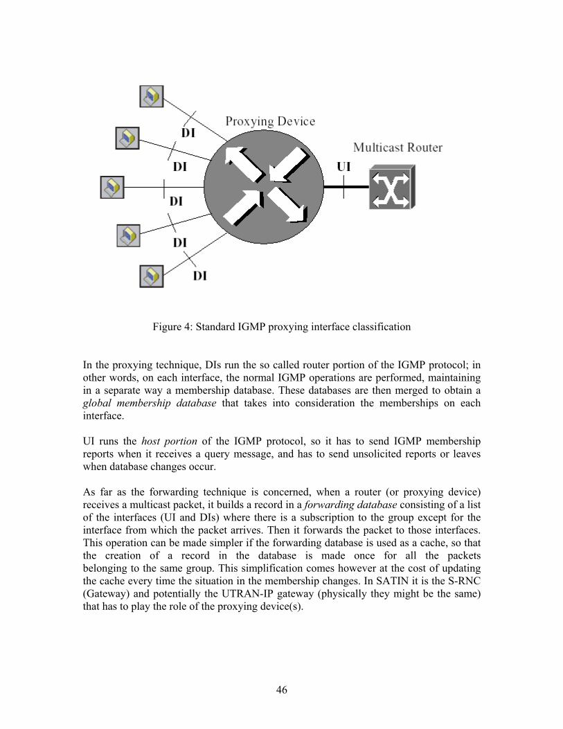
Figure 4: Standard IGMP proxying interface classification In the proxying technique, DIs run the so called router portion of the IGMP protocol; in other words, on each interface, the normal IGMP operations are performed, maintaining in a separate way a membership database. These databases are then merged to obtain a global membership database that takes into consideration the memberships on each interface. UI runs the host portion of the IGMP protocol, so it has to send IGMP membership reports when it receives a query message, and has to send unsolicited reports or leaves when database changes occur.
As far as the forwarding technique is concerned, when a router (or proxying device) receives a multicast packet, it builds a record in a forwarding database consisting of a list of the interfaces (UI and DIs) where there is a subscription to the group except for the interface from which the packet arrives. Then it forwards the packet to those interfaces. This operation can be made simpler if the forwarding database is used as a cache, so that the creation of a record in the database is made once for all the packets belonging to the same group. This simplification comes however at the cost of updating the cache every time the situation in the membership changes. In SATIN it is the S-RNC (Gateway) and potentially the UTRAN-IP gateway (physically they might be the same) that has to play the role of the proxying device(s).
46

The LAN-like nature of the network Rather than implying a strict resemblance with a Local Area Network (LAN), the term "LAN-like" refers to the capability of all the hosts within a beam to receive all transmissions destined for this beam. This capability can be exploited to reduce the number of exchanged IGMP messages over the air interface. Rather than letting every mobile host (MH) send reports back to the gateway, which implements the IGMP querier functionality, one of the multicast group members is elected as the group representative for IGMP proxy functions for the whole group. The other hosts trigger a timer whenever they see a report from the designated group proxy and only send their own report when this timer expires. The underlying principle is that the gateway does not have to be aware of the exact number of MHs participating in a given group but rather whether there is one or more MH(s) in a specific beam so that a copy of the message is forwarded to this beam. The requirement for the Max Response Time field is to be higher than the roundtrip time but reasonably low so as to reduce the number of membership report messages sent after the receipt of the General Membership Query. An instance of IGMP message exchanges, when both the aforementioned optimisations readopted, is shown in Figure 5. The figure illustrates the case of three Mobile Stations (MS) associated with a given Gateway (GW) which acts as querier. The difference in comparison with the fixed broadband access system case lies in that MS terminals are not connected to a CPE (Customer Premises Equipment, a device with layer 3 functionality in this case), which would take on the role of the IGMP proxy for them. A periodic General Membership Query (GMQ) message is broadcast to the cluster by the GW, which contains the selected Max Response Time. Upon receipt of the GMQ, the MS sets a delay timer for each group of which it is member. Timers are set to a random value selected from the range (0, Max Response]. In our example, MS#2 and MS#3 wish to receive traffic sent to the multicast address IP@1, while MS#1 has no active memberships. The first Membership Report message that is received comes from the MS#2, which, according to the overhead reduction protocol, becomes the elected group proxy. The GW broadcasts a Group_Proxy_Indication message (network signalling message) to inform all MSs in the cluster that MS#2 has been elected the group proxy for the address IP@1. From now on, all members of the group IP@1 except MS#2 can suppress membership report and leave messages. At the end of the session, MS#2 cancels its subscription to group IP@1 by sending a Leave message to the GW. As in standard IGMP, the latter sends a Specific membership Query to make sure that no other member of the group is active in the cluster. In our example, MS#3 is the remaining member of the group IP@1, therefore it will send a Membership Report to the GW, and will become the new group proxy for address IP@1. When MS#3 - last and single member of the group IP@1 - finally leaves this group there is no reply to the Specific Membership Query sent by the GW. When the timer for the subscription to the group IP@1 expires, the GW cancels the relevant soft state.
47
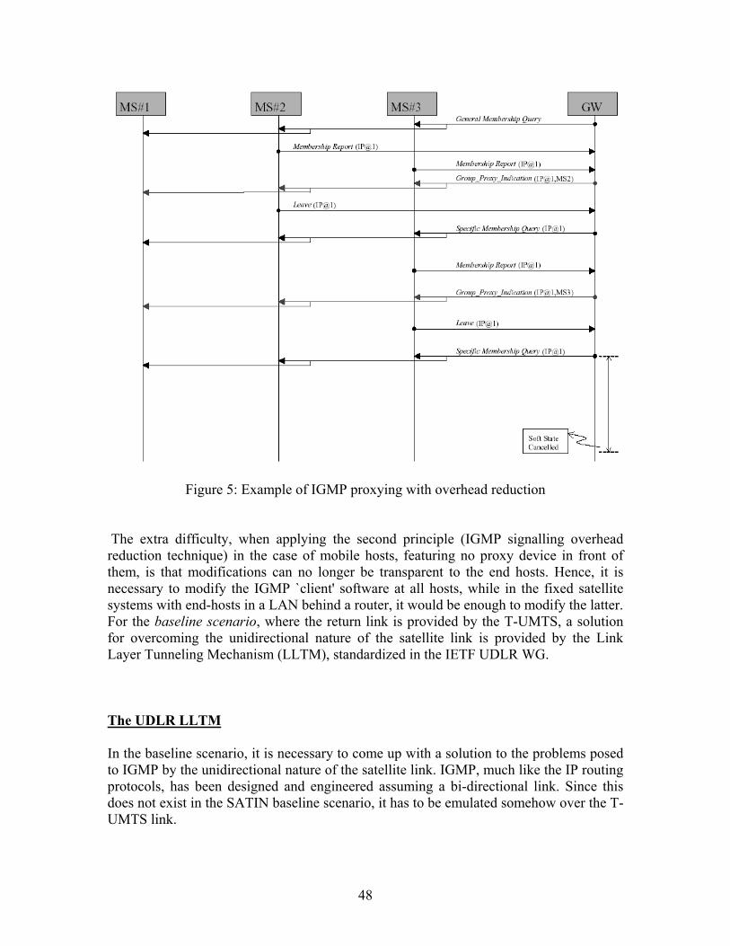
Figure 5: Example of IGMP proxying with overhead reduction
The extra difficulty, when applying the second principle (IGMP signalling overhead reduction technique) in the case of mobile hosts, featuring no proxy device in front of them, is that modifications can no longer be transparent to the end hosts. Hence, it is necessary to modify the IGMP `client' software at all hosts, while in the fixed satellite systems with end-hosts in a LAN behind a router, it would be enough to modify the latter. For the baseline scenario, where the return link is provided by the T-UMTS, a solution for overcoming the unidirectional nature of the satellite link is provided by the Link Layer Tunneling Mechanism (LLTM), standardized in the IETF UDLR WG.
The UDLR LLTM In the baseline scenario, it is necessary to come up with a solution to the problems posed to IGMP by the unidirectional nature of the satellite link. IGMP, much like the IP routing protocols, has been designed and engineered assuming a bi-directional link. Since this does not exist in the SATIN baseline scenario, it has to be emulated somehow over the T-UMTS link.
48
Such problems have mainly been addressed in the context of fixed satellite networks, where the unidirectional link is a satellite broadcast link (e.g. DVB-S) and there is a return terrestrial channel (e.g. dial-up line, PPP) that allows some form of interaction between the end-user and the provider/network operator. The IETF UDLR WG concluded the first part of its activities with the specification of a link-layer tunnelling mechanism, which effectively allows the emulation of a bi-directional link over a unidirectional link. Within the SATIN context, UDLR feeder/hub functions are required in the GW and UDLR receiver/host functions are required in the terminals. Multicast in a GPRS-based CN The implementation of multicast in this case seems to be a different case. The main reason for this is the different business paradigm of the two networks, namely the current, best-effort Internet and UMTS. In the former, there is intensive, time-based, signalling at the edges of the network, between the hosts and the closest multicast-capable router because there is no detailed state at the router upon the exact number or addresses of the hosts that receive multicast content. In other words, the only thing required by the router is to know whether there are one or more hosts that want to participate in a multicast session. In order to facilitate this, the end hosts are subject to this frequent IGMP message exchange. In effect, the trade-off between signalling overhead and router complexity is determined in favour of the latter, the underlying assumption being that at the edge of the network the luxury of wasting some bandwidth on additional signalling is feasible. On the contrary, in a mobile, wireless network like UMTS, there is generally much more information for the end user available at the network nodes. This information is available anyway in order to support the user mobility and AAA (Authentication, Authorization and Accounting) functions. The additional capability in the GPRS networks is the capability to use this information when `routing' each packet in pre-established tunnels that are created during the multicast PDP contexts. Therefore it is feasible for the SGSN to route traffic between the two access networks (T- and S- UMTS), since it is only necessary to set up the tunnels initially and make the respective bindings. This is not feasible, at least on the basis of the standard datagram routing paradigm. Therefore the IGMP-related issues become of less (or even no) relevance in this case, since the information provided by IGMP is `there' and, most significantly, can be used for routing packets to the users. TCP and UDP/RTP transport The TCP/IP suite provides applications mainly with two transport capabilities, expressed by Transport Control Protocol (TCP) and User Datagram Protocol (UDP). The former provides a reliable, byte-stream, connection-oriented service and is the workhorse
49
protocol for the traditional (and most popular) Internet applications, while the latter a connectionless service that is often used by real-time services, with an intermediate session/application level protocol providing the respective control functions. TCP FLOWS The provision of asymmetric, TCP-based services is envisaged within SATIN particularly in the optional scenario, given the interactivity these services require. In the baseline scenario the required interactivity will be provided via the terrestrial return link. The problems TCP faces over satellite links have been a subject of research for quite some time, although it experienced a peak in the last 5-6 years. The propagation delay related to a GEO satellite and the wireless nature of the satellite link, are the main factors of TCP performance degradation. The former reduces the effectiveness of the window-based flow control of the protocol and its responsiveness to congestion incidents. The latter interacts badly with the protocol congestion control mechanisms. Although the requirement to be accommodated over satellite links was identified from the very early days of the Internet, the main TCP congestion control algorithms were devised subsequently with the underlying assumption of an error-free link: therefore any indication of packet loss is interpreted as congestion incidence at the terrestrial network. TCP flows are adaptive, in that when they sense congestion they cut down on their sending rate and adjust to the capacity that is available to them, at least their estimation of it. In a wireless network, especially one with a one-hop link without any buffer intervening (like in the case of the non on-board switching capable satellite envisaged for SATIN) losses are due to link errors. Given that TCP works end-to-end, it cannot differentiate between a corruption and congestion loss and reduces its sending rate even when there is no reason for that (e.g. congestion), leading to reduced throughput. The SATIN architecture might feature another reason for TCP performance degradation: asymmetry, which is expressed as bandwidth asymmetry in the optional case and as both path and bandwidth asymmetry in the baseline case, where the T-UMTS network provides the return link. In fact this asymmetry is most of the times an engineering choice that fits the asymmetrical nature of some applications (traditional IP client-server applications). Asymmetric effects may be the result of asymmetry in the available capacity in the two directions of a TCP transfer, additional latency in one of the links due to medium sharing, usually in the return link, and can exaggerated or smoothed depending on the traffic load and the respective queuing delays in each one of the two directions. Such phenomena can have a negative impact on the TCP throughput, since the pacing of the ACK packets in a slower return link limits the sending rate of the TCP sender in the forward direction and prevents it from using potentially available capacity. When bandwidth asymmetry is combined with increased traffic load at the return link the effect can be even more dramatic due to the high queuing delays or losses of ACK packets, depending on the buffer sizes at the slow return link
50

A number of ways to attack these problems have been proposed. The majority of the solutions suggest transport (TCP)-level modifications, introducing different implementations of either the TCP sender or the receiver or both. Timestamps, window scaling and larger initial window are considered a MUST in `long fat networks, namely networks involving links with a large bandwidth-delay product. Furthermore TCP implementations with more elaborate flow control mechanisms (like TCP Vegas) or better response to congestion (Selective Acknowledgements, New Reno) than the standard Tahoe and Reno TCP have reported performance improvement, although they are not tailored for satellite links. Proxying techniques report much more promising results. TCP Spoofing, TCP Splitting and even TCP-aware link level schemes like Snoop outperform the standard end-to-end TCP connections. Although there are some arguments against their use, associated mainly with the extent to which they adhere to the `end-to-end' principle and their incompatibility with the use of network-level security mechanisms like IPSEC, such techniques are known to the satellite community and have been widely used in fixed satellite networks. In fact a combination of split connections with link-level retransmissions yields superior performance and guarantees some resilience to the terrestrial network level of congestion. The RLC retransmission protocol may be a further subject of differentiation with respect to T-UMTS. The ARQ protocol deployed in the case of optional scenario cannot have the persistence of the terrestrial analogues. It is also established that typical connection-oriented link layer protocols, attempting in order delivery of packets/frames interact badly with TCP. Regarding asymmetry: for a start, the range of possible solutions that can smoothen the asymmetric phenomena may be divided into host-side and network-side ones: in the former case the improvement comes from modifications in the protocol stacks of the sender, the receiver or both, while in the latter, changes in the network elements transparent to the end TCP host- are responsible for any performance enhancement. A significant number of techniques are in an experimental stage. Regarding the end-to-end mechanisms, an agreement appears to exist upon the benefit of the TCP connections from the use of the Path MTU Discovery mechanism that can save performance degradation due to potential network-level fragmentation. TCP Pacing is also promising in the sense that it does not necessitate major changes that could affect other standard connections in an adverse manner. ACK Congestion Control, a technique that attempts to expand the TCP data congestion control algorithms to the ACK packets, is in an experimental stage. Cruder solutions like Modified Delayed ACKs, that reduce the number of ACK packets sent at the return direction, are not favored since they increase the TCP sender burstiness and may trigger unwanted effects in the forward direction. Although some of the end-to-end mechanisms are promising, the SATIN context favors the network side, end-user transparent solutions for the mitigation of any asymmetry
51
effects. The complexity argument that usually acts preventively in such cases is well outweighed by the promised performance improvement and the scalability of the approach. It is also the centralized, radio access architecture of SATIN that favors such solutions; the bottleneck link is placed between the mobile terminal and the gateway, allowing the latter to exercise a number of techniques to alleviate any undesirable asymmetry effects -note that in this case asymmetry is the result of engineering action rather than a physical medium limitation (as would be the case in terrestrial, dial-up connections for example). The use of header compression techniques can limit the traffic load of ACK packets at the return link. Both the traditional Van Jacobson algorithm and more recent algorithms investigated mainly by the IETF ROHC (Robust Header Compression) group fitting better to the non error-free wireless environments may be adopted in the system design. In fact the aforementioned schemes/frameworks have been adopted by 3GPP, while specifying the Packet Data Convergence Protocol (PDCP). Furthermore, differentiation in the treatment of ACK packets will be provided by the use of appropriate scheduling mechanisms at the S-RNC node. More innovative solutions like ACK Reconstruction and ACK Compaction/Companding that provide some form of the ACK packet stream regeneration, and are exercised immediately after the bottleneck router are not favoured within SATIN, given that the experience from the use of such techniques is rather limited and their use not recommended. UDP FLOWS The efficient support of interactive real-time services (e.g. VoIP) is not possible within SATIN. The GEO satellite network introduces high latency, which becomes unacceptable in the case that a MS would like to communicate with another MS, implying a double-hop within the satellite network (MS-SRNC-MS). On the other hand, UDP is also the common choice for the transport of audio and video services, which constitute core services of the SATIN portfolio. A whole family of protocols, namely the Real Time Protocol (RTP), the Real Time Control Protocol (RTCP) as well as the Real Time Streaming Protocol (RTSP) have been devised for the support of IP-based (streaming) multimedia services. Multicast transport channels are often used for the transport of these services. IP QoS SUPPORT Support of IP quality of service in the SATIN scenario brings a number of issues that are worth investigating. Making the assumption that the core network will be based on an IP DiffServ solution, given its proven scalability compared to IntServ, careful considerations must be made with respect to how DiffServ or IntServ will be used in the user and access domains
52

taking also into account the mappings between the IP mechanisms and the underlying UMTS capabilities. The SATIN baseline scenario assumes a bi-directional communication where each direction follows a different path, i.e. the forward link is via gateway/satellite/gap filler, whereas the return link is via T-UMTS. This has an impact on the way the IP QoS mechanisms will be used. According to the RSVP specifications (within the context of IntServ), the RSVP PATH and RESV message objects must traverse the same route. This is done since the PATH message records the path along which the reservations will be made when the remote end send back the RESV messages. However, this is not the case with the SATIN architecture. The concept of the RSVP proxy may be used to overcome this problem. RSVP proxy functionality can also be used when RSVP client functionality is not implemented in the MS. More specifically, if the MS does not have the required IP QoS capabilities in order to provide end-to-end QoS, IP layer signaling may be performed in the IP and RAN gateway (e.g. RNC/GGSN) and be transferred transparently through the DiffServ core. The required QoS information can then be signaled between the MS and the RAN gateway using UMTS mechanisms. Moreover, admission control plays a vital role in the IntServ framework, as it is required in each RSVP-capable node. In contrary to wire-line networks, a number of additional factors need to be considered such as mobility and its interaction with other RRM functions. Indeed RSVP signalling should be avoided over the air. If SIP is being used then RSVP messages can be created by the GGSN by combining UMTS and SDP QoS information. The mapping of the IntServ service classes and associated QoS parameters to the UMTS classes is another aspect that needs investigation, taking particular care of the satellite link characteristics. With DiffServ, the implications are mainly related to handover and mobility. When a mobile terminal with a specific SLS moves from one domain to another, there are no guaranties that the new domain will have enough resources to comply with the SLA because of the shared nature of the access network. In addition, the new domain may belong to another Service Provider that utilizes a different pricing scheme thus complicating things more. The application QoS is interpreted (PDP), the Serving RNC controls admission of new flow to the pre-established Iu-Packet Switched bandwidth pipe (DiffServ IP, IP bearer / QoS guaranteed pre-negotiated with ISP, traffic control is set based on SLS) and QoS mappings are performed inside and at the border of UMTS RAN (mapping between UMTS QoS Class and DiffServ done in the SGSN for Forward/Downlink and in the RNC for the Return/Uplink).
53
CONCLUSIONS
UMTS is seen as the enabler of wireless multimedia applications and portability of a personalized service set across network and terminal boundaries, as defined within the virtual home environment system concept. This project investigates the evolution toward an all-IP UMTS system architecture, clarifying the impact of an IP-based core network design on the UMTS service architecture. Two possible scenarios are discussed for supporting VoIP services in a UMTS service architecture based on the principles of the VHE. On one hand, there are the classical centralized IN-type service control architectures, which remain very important for continuing support of legacy IN services. On the other hand, there is the new decentralized OSA-type service provisioning architecture, which appears to be very interesting for flexible deployment of future innovative multimedia services. Because each of the two scenarios has its merits in certain situations, both types of interfaces will coexist and the solution will lie in the optimal selection of the type of interface most suitable to provide a particular service. We provide a classification of the number of ways in which IP, together with MPLS, may be used to build a mobile operator's infrastructure. While most existing proposals for an all-IP network use IP for transport purposes only, our proposed network model illustrates the benefits of using IP in the native mode in the access agnostic segments of the administrative domain. We argue that such a model allows for the deployment of heterogeneous access networks, all supported by the same core network. Furthermore, we provide the means for intradomain micromobility, seamless across access networks, based on the underlying MPLS layer. We need to note that this is in a nascent stage of research, and the forthcoming protocol details need to progress through the standardization process before contemplating its deployment. In SATIN the satellite component of UMTS is no more a standalone system that would only provide a coverage extension to the PLMN for a subset of services but rather a complementary means of service delivery in co-operation with the terrestrial access network, since Multi/Broad-casting over wide areas is best served by satellites. Regarding the multicast support, which is the key issue within the SATIN context, the goal pursued in SATIN at first place is smooth integration into UMTS. Therefore the architecture features a satellite RNC interfaced to GPRS backbone with some provision for evolving with the possible IP penetration in the 3GPP core. For the SATIN baseline architecture the support of prime SATIN multicast services (i.e. no real-time interaction of the Return and Forward links required) favors the following main architecture features:
• Support of common features for the MBMS multicast and broadcast modes, e.g. both modes shall preferably use the same low-layer bearer for data transport over the radio interface.
54
• Support of external data sources in both modes (both IP multicast and unicast sources). MBMS shall be a point-to-multipoint service in the PS domain.
• Home environment requirements of MBMS stage 1, inter alia Multicast Area • IP multicast capability in GGSN • Use of GTP (i.e. GTP-U protocol in the User plane and GTP-C signalling), in
the terrestrial path and in the satellite path till the satellite RNC.
The transport service offered to multicast is an unreliable one leaving the responsibility for reliability provision to the upper layers. It remains to be seen as to when the actual full-scale implementation of UMTS will take place, but definitely we can endeavor to dig deep into its perspective in its foetal stage and evolve a true 3G network.
55
REFERENCES
[1] The 3GPP initiative, http://www.3gpp.org [2] The 3GPP2 initiative, http://www.3gpp2.org [3] The IMT-2000 initiative, http://www.itu.int/imt [4] 3GPP Technical Report 23.821 v 1.0.0, "Architectural principles for R00," June 2000, http://www.3gpp.org/ftp/Specs/June_00/23_series/23821-100.zip [5] J. Postel, "IETF RFC 791, IP: Internet Protocol," Sep. 1981, http://www.ietf.org/rfc/rfc0791.txt [6] 3GPP Technical Specification 23.127 v 3.0.0, "Virtual Home Environment/Open Service Architecture," Mar. 2000, http://www.3gpp.org/ftp/Specs/March_00/23_series/23127-300.zip [7] T. Magedanz and R. Popescu-Zeletin, Intelligent Networks, Basic Technology, Standards and Evolution, Int'l. Thomson, 1992 [8] H. Schulzrinne, "IETF RFC 2543, SIP: Session Initiation Protocol," Mar. 1999, http://www.ietf.org/rfc/rfc2543.txt [9] ITU-T Rec. H.323, "Packet based Multimedia Communications Systems," 1998, http://www.itu.int/itudoc/itu-t/rec/h/h323.html [10] 3GPP TS 23.002, "Network Architecture," rel. 5, v. 5.6.0, http://www.3gpp.org/ , Mar. 2002. [11] 3GPP TS 25.401, "UTRAN Overall Description," rel. 5, v. 5.2.0, http://www.3gpp.org/ , Mar. 2002. [12] G. Brasche and B. Walke, "Concepts, Services and Protocols of the New GSM Phase 2+ General Packet Radio Service," IEEE Commun. Mag., vol. 35, no. 8, Aug. 1997. [13] E. Rosen, A. Viswanathan, and R. Callon, "Multiprotocol Label Switching Architecture," IETF RFC 3031, Jan. 2001. [14] Mobile Wireless Internet Forum, "IP in the RAN as a Transport Option in 3rd Generation Mobile Systems," Tech. rep. MTR-006, v. 2.0.0, June 2001. [15] 3GPP TR 23.922, "Architecture for an All-IP Network," rel. 4, http://www.3gpp.org/ Mar 2001. [16] C. Perkins, Ed., "IP Mobility Support," IETF RFC 2002, Oct. 1996. [17] A. T. Campbell et al., "Design, Implementation and Evaluation of Cellular IP," IEEE Pers. Commun., Aug.2000, pp. 4249. [18] R. Ramjee et al., "HAWAII: A Domain-Based Approach for Supporting Mobility in Wide-Area Wireless Net-works," Proc. IEEE Int'l. Conf. Net. Protocols, 1999. [19] E. Gustafsson, A. Jonsson, and C. Perkins, "Mobile IP Regional Registration," Internet draft, draft-ietf-mobileip-reg-tunnel-06.txt, Mar. 2002, work in progress. [20] H. Soliman et al., "Hierarchical MIPv6 Mobility management," Internet draft, draft-ietf-mobileip-hmipv6-05.txt, July 2001. [21] J. Grimminger and H. P. Huth, "Mobile MPLS --an MPLS-Based Micro Mobility Concept," WL World Research Forum, Mtg. 3, Stockholm, Sweden, Sept. 2001. [22] IST Wine Glass Project, http://domobili.cselt.it/WineGlass.
56
[23] Mobile Wireless Internet Forum, `IP in the RAN as a transport option in 3rdgeneration Mobile Systems' , Technical Report MTR-006v2, April 2001. [24] Universal Mobile Telecommunications System (UMTS); MBMS; Architecture and functional description, 3GPP TR 23.846, Release 5, v0.0.1 [25] SATIN Project, `S-UMTS IP-specific service requirements' , Deliverable No. 2, October 2001. [26] B. Fenner, `IGMP-based multicast forwarding (`IGMP Proxying'), Internet draft (Work in progress), July 2001. [27] M. Allman et al., `Ongoing TCP research related to satellites' , RFC 2760, February 2000. [28] J. Border et al., `Performance enhancing proxies intended to mitigate link-related degradations' , RFC 3135, June 2001. [29] H. Balakrishnan et al., `TCP performance implications of network asymmetry' , Internet draft (work-in-progress), November 2001.
57