csci-690 c omputer networks: shrinking the globe one click at a time lecture 3
DESCRIPTION
CSCI-690 C omputer Networks: Shrinking the globe one click at a time Lecture 3. Khurram Kazi. Major sources of the slides for this lecture. Slides from Tanenbaum’s and William Stallings’ website are used in this lecture - PowerPoint PPT PresentationTRANSCRIPT

New York Institute of Technology
Engineering and Computer Sciences
Fall 2008 CSCI 690
CSCI-690Computer Networks:
Shrinking the globe one click at a time
Lecture 3
Khurram Kazi
New York Institute of Technology
Engineering and Computer Sciences
Fall 2008 CSCI 690 2
Major sources of the slides for this lecture
Slides from Tanenbaum’s and William Stallings’ website are used in this lecture
Interworking with TCP/IP, M9000-02, Global knowledge, training manual, (http://am.globalknowledge.com)
Teach yourself TCP/IP in 24 hours, Joe Casad, Bob Willsey, SAMS
The Internet and Its Protocol, Adrian Farrel’s book.

New York Institute of Technology
Engineering and Computer Sciences
Fall 2008 CSCI 690 3
Topics for the next few weeks
For the next few weeks we will concentrate on:
Protocols IPTCP / UDP
IP Addressing Go through an example of the Life of a
Packet in a Network In the process we will develop a
functional model of a ROUTER.

New York Institute of Technology
Engineering and Computer Sciences
Fall 2008 CSCI 690 4
Reference Network: For discussion purposes
Router A
Router B
Router C
Router D
Router F
Router E
LAN 1
LAN 2
Wide Area Network or Metro Area Network
Edge Router
Edge Router
Source of IP Traffic
Destination of IP Traffic (server)
Shows traffic flow
ip addr
ip addr
ip addr
ip addr
ip addr
ip addr
ip addr
ip addr

New York Institute of Technology
Engineering and Computer Sciences
Fall 2008 CSCI 690 5
Source of IP Traffic Application Traffic type could be
FTP (file transfer) Instant messaging Secure or non-secure web access Streaming video Document sharing (similar to net meeting) Database access (across the street or across the
continent) Voice over IP
It all boils down to what protocols are used

New York Institute of Technology
Engineering and Computer Sciences
Fall 2008 CSCI 690 6
Summarizing Features of the Protocol Functions
have a small set of functions that form basis of all protocols Encapsulation (e.g. IP packets encapsulated in Ethernet frames) fragmentation and reassembly (e.g. fragmentation of a file
during an FTP and reassembly of it at the destination) connection control (e.g. during TCP session) ordered delivery flow control error control addressing multiplexing transmission services

New York Institute of Technology
Engineering and Computer Sciences
Fall 2008 CSCI 690 7
PDUs (Protocol Data Units) and Fragmentation
Example: Fragmentation seen during file transfer using FTP
This can be an IP Packet
This can be a TCP component of the Packet

New York Institute of Technology
Engineering and Computer Sciences
Fall 2008 CSCI 690 8
Demonstrate file transfer using FTP while capturing the data by Wireshark
Starting from the traffic source

New York Institute of Technology
Engineering and Computer Sciences
Fall 2008 CSCI 690 9
Fragmentation and Reassembly
Protocol exchanges data between two entities Lower-level protocols may need to break data up into
smaller blocks, called fragmentation For various reasons
Network only accepts blocks of a certain size More efficient error control & smaller retransmission units Fairer access to shared facilities Smaller buffers
Disadvantages Smaller buffers More interrupts & processing time

New York Institute of Technology
Engineering and Computer Sciences
Fall 2008 CSCI 690 10
Starting the protocol stack analysis with The IP Protocol (RFC 791) http://www.ietf.org/rfc/rfc0791.txt?number=791
The IPv4 (Internet Protocol) header.0 1 2 3 4 5 6 7 0 1 2 3 4 5 6 7 0 1 2 3 4 5 6 7 0 1 2 3 4 5 6 7
Octet 1 Octet 2 Octet 3 Octet 4
Version IHL Type of Service Total Length
Identification Flags Fragment Offset
Source Address
Destination Address
Options Padding
Data (payload) portion of the datagram
1st 32 bit word
2nd 32 bit word
3rd 32 bit word
4th 32 bit word
nth 32 bit word
Time to Live Protocol Header Checksum
5th 32 bit word
New York Institute of Technology
Engineering and Computer Sciences
Fall 2008 CSCI 690 11
IP Header Fields continued
Version (4 bits) (whether the format is of type)
currently IP v4 IP v6
Internet Header Length (IHL) (4 bits) Is the length of header in 32 bit words, Points to the beginning of the data
(payload) including optionsMinimum value for a correct header is 5

New York Institute of Technology
Engineering and Computer Sciences
Fall 2008 CSCI 690 12
IP Header Fields continuedType of Service (8 bits) (see RFC 791 for details)
Is an indication of the abstract parameters of the Quality of Service (QoS) desired. These parameters are to be used to guide the selection of the actual service parameters when transmitting a datagram through a particular network. Several networks offer service precedence, which somehow treats high precedence traffic as more important than other traffic (generally by accepting only traffic above a certain precedence at time of high load). The major choice is a three way tradeoff between low-delay, high-reliability, and high-throughput.
Bits 0-2: Precedence: Primarily used within a particular network111 - Network Control 110 - Internetwork Control 101 - CRITIC/ECP 100 - Flash Override 011 - Flash 010 - Immediate 001 - Priority
000 - Routine
New York Institute of Technology
Engineering and Computer Sciences
Fall 2008 CSCI 690 13
IP Header Fields continued
Type of Service (8 bits) (see RFC 791 for details) Is an indication of the abstract parameters of the Quality of
Service (QoS) desired. These parameters are to be used to guide the selection of the actual service parameters when transmitting a datagram through a particular network. Several networks offer service precedence, which somehow treats high precedence traffic as more important than other traffic (generally by accepting only traffic above a certain precedence at time of high load). The major choice is a three way tradeoff between low-delay, high-reliability, and high-throughput.
Bit 3: 0 = Normal Delay, 1 = Low Delay. Bits 4: 0 = Normal Throughput, 1 = High Throughput. Bits 5: 0 = Normal Reliability, 1 = High Reliability.Bit 6 1 = minimize monetary cost [defined in RFC 1349]
Bit 7: Reserved for Future Use. Only one of the bits [6:3] can be set to a 1

New York Institute of Technology
Engineering and Computer Sciences
Fall 2008 CSCI 690 14
IP Header Fields continued Total Length (16 bits)
Total Length is the length of the datagram, measured in octets, including internet header and data. This field allows the length of a datagram to be up to 65,535 octets. Such length of a datagram are impractical for most hosts and networks.Since there is no “end of datagram” character/indicator, network hosts use the datagram length to figure out when the datagram ends and other network data begins.
Q. Can an IP datagram be as large as 65,535 octets when the data is transmitted over Ethernet (in LAN applications)?

New York Institute of Technology
Engineering and Computer Sciences
Fall 2008 CSCI 690 15
IP Header Fields continued
Identification (16 bits)An identifying value assigned by the sender
to aid in assembling the fragments of a datagram. It is assigned by the originating host. At the source, there is one-to-one relation between datagrams and datagram identifier. As these datagrams traverse the network, they could be split. Hence this field is used by the receiving host to reassemble the original datagram.

New York Institute of Technology
Engineering and Computer Sciences
Fall 2008 CSCI 690 16
IP Header Fields continued Flags (3 bits)
Bit 0: reserved, must be zero Bit 1: (DF) 0 = May Fragment, 1 = Don't Fragment.
Bit 2: (MF) 0 = Last Fragment, 1 = More Fragments. If the datagram cannot be routed without
being fragmented, the router will throw it away and send an error message back to the originating host.
When MF=1, it means that the datagram is one of the two or more fragments, but not the last one of the fragments. Receiving hosts use this flag along with the fragment offset to reassemble the fragmented datagrams.

New York Institute of Technology
Engineering and Computer Sciences
Fall 2008 CSCI 690 17
IP Header Fields continuedFragment Offset (13 bits)This field specifies how many units from
the start of the original datagram the current datagram is. In other words, the first fragment datagram would have a value of 0 for the offset; if the second datagram starts 100 units from the beginning of the original datagram, the offset would be 100. the unit size is eight bytes (instead of one byte) since the field is only 13 bits wide.

New York Institute of Technology
Engineering and Computer Sciences
Fall 2008 CSCI 690 18
IP Header Fields continuedTime to Live (8 bits)This field indicated how long the
datagram should be allowed to exist after entering the internetwork, measuring in seconds (maximum TTL is 255). Presently as datagrams traverse a router, this number is decremented by one.This informally represents the maximum
number of hops that a datagram can make before being discarded.

New York Institute of Technology
Engineering and Computer Sciences
Fall 2008 CSCI 690 19
IP Header Fields continued
Protocol (8 bits)This field identifies the next higher
layer protocol of the data being carried in the datagram.
01 hexICMP06 hexTCP11 hexUDPhttp://www.ietf.org/rfc/rfc1700.txt?number=1700lists the different
protocols and their identifier numbers

New York Institute of Technology
Engineering and Computer Sciences
Fall 2008 CSCI 690 20
IP Header Fields continuedHeader Checksum (16 bits)This field provides error checking on
the IP header only, and does not cover the data that is carried at the end of the header. If the header is extended using the options field, then the checksum includes the extended header field too.
If the target IP-addressed interface receives a datagram with a failed checksum, the entire datagram is silently discarded.
New York Institute of Technology
Engineering and Computer Sciences
Fall 2008 CSCI 690 21
IP Header Fields continuedSource IP Address (32 bits)The sender’s interface’s 32-bit Internet
address is identified in four bytes/octets. e.g. C0 99 B8 01 Four pair of Hex characters 192.153.184.1
Find the decimal equivalent of the following IP address represented in Hex
0F 10 07 11 ---.---.---.--- ??

New York Institute of Technology
Engineering and Computer Sciences
Fall 2008 CSCI 690 22
IP Header Fields continued
Destination IP Address (32 bits)The target’s host’s 32-bit Internet
address is identified in four bytes/octets. e.g. C0 99 B8 03 Four pair of Hex characters 192.153.184.3

New York Institute of Technology
Engineering and Computer Sciences
Fall 2008 CSCI 690 23
Connectionless Transport with User Datagram Protocol (UDP)
Connectionless protocols have the ability to transmit messages without first establishing a circuit.
The network does not need to do anything except transmit packets to the destination
All error checking and flow control is handled by the sending and receiving applications
` `
Data
New York Institute of Technology
Engineering and Computer Sciences
Fall 2008 CSCI 690 24
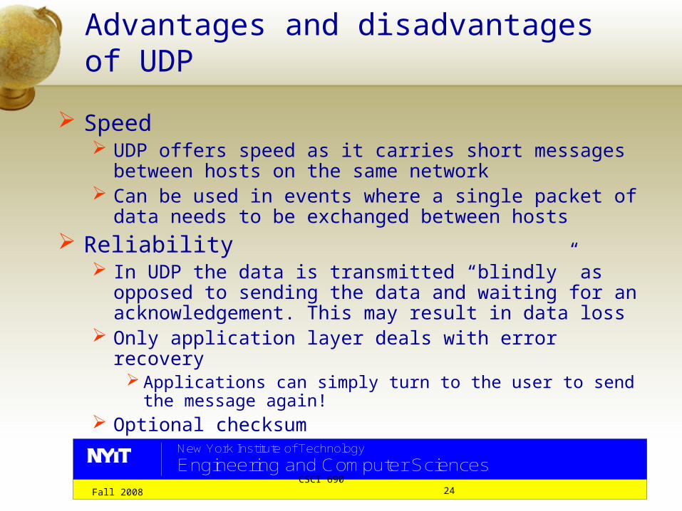
Advantages and disadvantages of UDP
Speed UDP offers speed as it carries short messages between
hosts on the same network Can be used in events where a single packet of data
needs to be exchanged between hosts Reliability
In UDP the data is transmitted “blindly” as opposed to sending the data and waiting for an acknowledgement. This may result in data loss
Only application layer deals with error recovery Applications can simply turn to the user to send the
message again! Optional checksum

New York Institute of Technology
Engineering and Computer Sciences
Fall 2008 CSCI 690 25
UDP Header
0 1 2 3 4 5 6 7 0 1 2 3 4 5 6 7 0 1 2 3 4 5 6 7 0 1 2 3 4 5 6 7
Octet 1 Octet 2 Octet 3 Octet 4
Source Port Destination Port
UDP Length UDP Checksum (optional)
1st 32 bit word
2nd 32 bit word

New York Institute of Technology
Engineering and Computer Sciences
Fall 2008 CSCI 690 26
UDP Header The process layer uses TCP or UDP to pass information
to the internetwork layer. It is necessary to identify the client or server tasks uniquely so that the information is passed to the proper service or user task. The identification used in the TCP/IP protocol is called the “Port Number”.
UDP and TCP identify server tasks by using a port number that is consistent and well known. To access a service such as DNS (Domain Name Server), the software knows that DNS is waiting for sessions to be established at port 53.
Client tasks are identified by using port numbers that are variable and temporary, called random port numbers. The client random port numbers exist during the communication process and are discarded when the communication process is complete.

New York Institute of Technology
Engineering and Computer Sciences
Fall 2008 CSCI 690 27
UDP Headers
Port 53
Port 69 Port
161
Port 8193
Random Ports
Server
ClientClient computer creates random ports as needed
Port 53 = Domain Name Server (DNS)

New York Institute of Technology
Engineering and Computer Sciences
Fall 2008 CSCI 690 28
UDP Headers
Port 53
Port 69 Port
161
Port 8193
Random Ports
Server Client
Port 53 = Domain Name Server (DNS)
IP Address: 192.136.118.30 Port: 53
IP Address: 192.153.118.30 Port: 8193
The term sockets refers to both an API (application program interface) between host systems and the TCP/IP applications, and a pairing of the IP address and the port number being used. It is also considered the complete network address of an end of the UDP session.
In the language of UDP, the sockets in the figure are 192.136.118.30,53 and 192.153.118.30,8193
This indicates the client is asking for DNS service

New York Institute of Technology
Engineering and Computer Sciences
Fall 2008 CSCI 690 29
Connection Oriented protocol
Setup Request
Setup Response
Data
Acknowledge
Clear connection
Clear response

New York Institute of Technology
Engineering and Computer Sciences
Fall 2008 CSCI 690 30
Connection Oriented Protocol A connection oriented protocol establishes
and maintains a connection between communicating computers and monitors the state of that connection over the course of transmission. Each package of data sent across the network receives an acknowledgement, and the sending machine records status information to ensure each package is received without errors. At the end of the transmission, the sending and receiving computers gracefully close the connection.
This method is used by reliable transport services
TCP is connection oriented protocol. [RFC 793]

New York Institute of Technology
Engineering and Computer Sciences
Fall 2008 CSCI 690 31
Features of TCP [RFC 793]: Stream Oriented Processing TCP processes data in a bytes stream. TCP formats the
data into variable length segments which it will pass to the IP Layer.
In general, the TCPs decide when to block and forward data at their own convenience. Sometimes users need to be sure that all the data they have submitted to the TCP has been transmitted. For this purpose a push function is defined.
To assure that data submitted to a TCP is actually transmitted the sending user indicates that it should be pushed through to the receiving user. A push causes the TCPs to promptly forward and deliver data up to that point to the receiver. The exact push point might not be visible to the receiving user and the push function does not supply a record boundary marker.

New York Institute of Technology
Engineering and Computer Sciences
Fall 2008 CSCI 690 32
Features of TCP: Reliability/Re-sequencing The TCP must recover from data that is
damaged, lost, duplicated, or delivered out of order by the internet communication system. This is achieved by assigning a sequence number to each octet transmitted, and requiring a positive acknowledgment (ACK) from the receiving TCP.
If the ACK is not received within a timeout interval, the data is retransmitted. At the receiver, the sequence numbers are used to correctly order segments that may be received out of order and to eliminate duplicates.
Damage is handled by adding a checksum to each segment transmitted, checking it at the receiver, and discarding damaged segments.

New York Institute of Technology
Engineering and Computer Sciences
Fall 2008 CSCI 690 33
Features of TCP: Flow Control
TCP flow control feature ensures that the data transmission will not overflow or underflow the destination machine’s capability to receive data. This is a very critical feature as different machines may have different processor speeds and buffer sizes.
TCP provides a means for the receiver to govern the amount of data sent by the sender. This is achieved by returning a "window" with every ACK indicating a range of acceptable sequence numbers beyond the last segment successfully received. The window indicates an allowed number of octets that the sender may transmit before receiving further permission.

New York Institute of Technology
Engineering and Computer Sciences
Fall 2008 CSCI 690 34
Features of TCP: Multiplexing To allow for many processes within a single Host to use
TCP communication facilities simultaneously, the TCP provides a set of addresses or ports within each host. Concatenated with the network and host addresses from the internet communication layer, this forms a socket. A pair of sockets uniquely identifies each connection. That is, a socket may be simultaneously used in multiple connections.
The binding of ports to processes is handled independently by each Host. However, it proves useful to attach frequently used processes (e.g., a "logger" or timesharing service) to fixed sockets which are made known to the public. These services can then be accessed through the known addresses. Establishing and learning the port addresses of other processes may involve more dynamic mechanisms.

New York Institute of Technology
Engineering and Computer Sciences
Fall 2008 CSCI 690 35
Features of TCP:Connections The reliability and flow control mechanisms described above
require that TCPs initialize and maintain certain status information for each data stream. The combination of this information, including sockets, sequence numbers, and window sizes, is called a connection. Each connection is uniquely specified by a pair of sockets identifying its two sides.
When two processes wish to communicate, their TCP's must first establish a connection (initialize the status information on each side). When their communication is complete, the connection is terminated or closed to free the resources for other uses.
Since connections must be established between unreliable hosts and over the unreliable internet communication system, a handshake mechanism with clock-based sequence numbers is used to avoid erroneous initialization of connections.
Graceful termination: The graceful termination feature ensures that all segments have been sent and received before a connection is closed.

New York Institute of Technology
Engineering and Computer Sciences
Fall 2008 CSCI 690 36
Features of TCP:Connections; in a nutshell
A connection is established between {source IP address, source port} and {destination IP address, destination port}.
Connection ensures that applications are present at both sender and receiver and negotiates capabilities for use on the connection.
New York Institute of Technology
Engineering and Computer Sciences
Fall 2008 CSCI 690 37
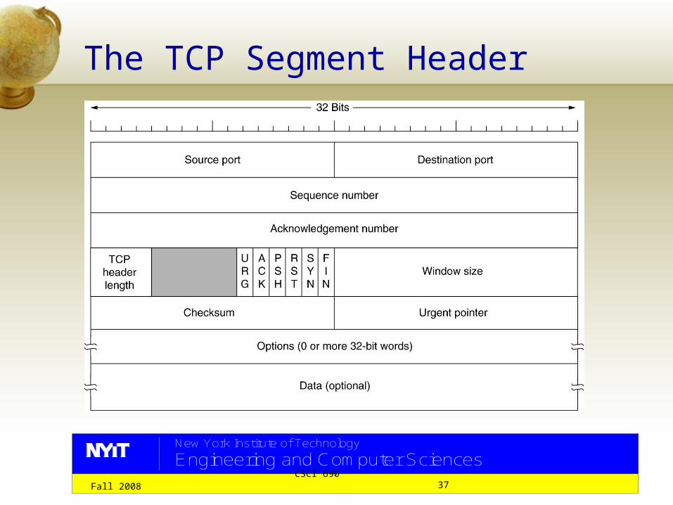
The TCP Segment Header

New York Institute of Technology
Engineering and Computer Sciences
Fall 2008 CSCI 690 38
TCP Headers explained
Source port: (16 bits) – The port number assigned to the application on the source machine
Destination port: (16 bits) – The port number assigned to the application on the destination machine

New York Institute of Technology
Engineering and Computer Sciences
Fall 2008 CSCI 690 39
TCP Headers explained
Sequence Number: (32 bits) – The number of the first byte in this particular segment, unless SYN flag is set to one. If SYN Flag is set to a 1, the sequence number field provides the Initial Sequence Number (ISN), which is used to synchronize sequence numbers.
Sequence number DOES NOT represent how many bytes of user data may be in that segment
# of bytes of user data = IP total length – (IP + TCP Header bytes)

New York Institute of Technology
Engineering and Computer Sciences
Fall 2008 CSCI 690 40
TCP Headers explainedSequence Number: The sequence
number are chosen arbitrarily, rather than always starting at some standard number (e.g. 1). This to avoid confusing the system when a host unexpectedly is turned off (or crashes). If the system came back up soon enough after having started a TCP connection and attempted to reopen that connection, the remote would not be able to determine if the data being sent was a duplicate copy of the data it already received.

New York Institute of Technology
Engineering and Computer Sciences
Fall 2008 CSCI 690 41
TCP Headers explained
Acknowledgement Number: (32 bits) -- This number acknowledges a received segment. The value is the next sequence number the receiving computer is expecting to receive; in other words, the sequence number of the last byte received + 1.
For example from the sender if the seq. # was 12, then the ack. Seq. # sent from the receiver to the sender will be 13 (which 12 + 1).

New York Institute of Technology
Engineering and Computer Sciences
Fall 2008 CSCI 690 42
TCP Headers explained
TCP Header Length: (4 bits) – The field tells the length of the TCP header. It is expressed as an integer number of 32-bit words. For example a value of 5 will translate into 20 bytes.

New York Institute of Technology
Engineering and Computer Sciences
Fall 2008 CSCI 690 43
TCP Headers explained: Session Bits Flags
First two bits of the octet are reserved, i.e. not used. URG – Urgent data: If this bit is set to a 1, some of the data
in this segment must be processed before all other data. The data usually makes changes in the state of the session.
ACK – Valid Acknowledgement: When this bit is set to a 1, the data in the acknowledgement field is a valid number.
PSH – Push Request: When set to a 1, it tells the TCP software to push all the data sent so far through the pipeline to the receiving application.
RST – Reset Session: A value of 1 resets the connection. SYN – When set to a 1, it announces that the sequence
numbers will be synchronized, marking the beginning of a connection.
FIN – Final Data: A value of 1 signifies that the sending computer has no more data to transmit. This flag is used to close a connection.

New York Institute of Technology
Engineering and Computer Sciences
Fall 2008 CSCI 690 44
TCP Headers explained
Window Size: (16 bits) A parameter used for flow control. The window size defines the range of sequence numbers beyond the last acknowledged sequence number that the sending machine is free to transmit without further acknowledgement.
http://www.raduniversity.com/networks/2004/sliding_window/demo.html
http://www.kom.e-technik.tu-darmstadt.de/projects/iteach/itbeankit/Applets/Sliding_Window/sliding_window.html#Selective%20Repeat

New York Institute of Technology
Engineering and Computer Sciences
Fall 2008 CSCI 690 45
TCP Headers explained
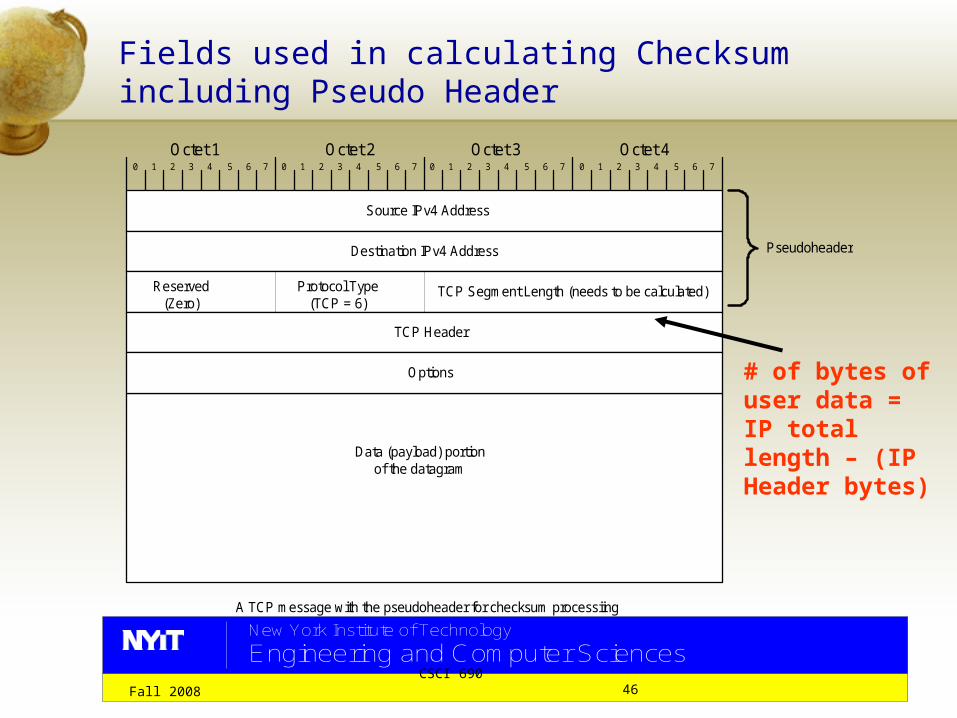
Checksum: The checksum field is the 16 bit one's complement of the one's complement sum of all 16 bit words in the header and text. If a segment contains an odd number of header and text octets to be checksummed, the last octet is padded on the right with zeros to form a 16 bit word for checksum purposes. The pad is not transmitted as part of the segment.
The checksum also covers a 96 bit pseudo header conceptually prefixed to the TCP header. This pseudo header contains the Source Address, the Destination Address, the Protocol, and TCP length. This gives the TCP protection against misrouted segments.
New York Institute of Technology
Engineering and Computer Sciences
Fall 2008 CSCI 690 46
Fields used in calculating Checksum including Pseudo Header
0 1 2 3 4 5 6 7 0 1 2 3 4 5 6 7 0 1 2 3 4 5 6 7 0 1 2 3 4 5 6 7
Octet 1 Octet 2 Octet 3 Octet 4
Source IPv4 Address
Destination IPv4 Address
Reserved (Zero)
TCP Segment Length (needs to be calculated)
Data (payload) portion of the datagram
Pseudoheader
Protocol Type (TCP = 6)
TCP Header
Options
A TCP message with the pseudoheader for checksum processiing
# of bytes of user data = IP total length – (IP Header bytes)

New York Institute of Technology
Engineering and Computer Sciences
Fall 2008 CSCI 690 47
Fields used in calculating Checksum including Pseudo Header (for UDP)
0 1 2 3 4 5 6 7 0 1 2 3 4 5 6 7 0 1 2 3 4 5 6 7 0 1 2 3 4 5 6 7
Octet 1 Octet 2 Octet 3 Octet 4
Source IPv4 Address
Destination IPv4 Address
Reserved (Zero)
UDP Length
Data (payload) portion of the datagram
Pseudoheader
Protocol Type (UDP = 17)
Source Port
A UDP message with the pseudoheader for checksum processiing
Destination Port
UDP Datagram Length UDP Checksum
UDP Header

New York Institute of Technology
Engineering and Computer Sciences
Fall 2008 CSCI 690 48
Example of Checksum Calculation
FFFF = 65535
HEX Decimal
Decimal Addtion with carry added HEX Equivalent Checksum
4500 17664003b 59 17723 453B581d 22557 40280 9D58
0 0 40280 9D588011 32785 7530 1D6Aaa81 43649 51179 C7EB4b53 19283 4927 133Faa81 43649 48576 BDC05296 21142 4183 1057
EFA8
40280 + 32785 = 73065; In Hex 9D58 + 8011 = 11D69
73065 – 65535 = 7530; In Hex remove the MSB and add 1 to 1D69 = 1D69 + 1 = 1D6A

New York Institute of Technology
Engineering and Computer Sciences
Fall 2008 CSCI 690 49
TCP Headers explained
Urgent Pointer: (16 bits) An offset pointer pointing to the sequence number that marks the beginning of any urgent information. Typically it is 0000 Hex.
When the target device is congested or has other data throughput problems, it clears the correct amount of buffer space to receive and process the urgent message.

New York Institute of Technology
Engineering and Computer Sciences
Fall 2008 CSCI 690 50
Connection Establishment
TCP connections are established and maintained on demand from applications and are kept active (barring network failure) until the applications explicitly release them
In order for the TCP connection to be established, the receiver must be listening– (similar to when a phone call is made the other party has to be present to answer it)
The application goes into listen mode

New York Institute of Technology
Engineering and Computer Sciences
Fall 2008 CSCI 690 51
Connection Establishment
Send a TCP open request with SYN bit = 1, and a sequence number of 167 & acknowledgement number 0
Host A Host B
Receive the open request, send back a packet with sequence number of 498, and acknowledgment number of 168SYN bit = 1, ACK = 1
Receive the acknowledgement packet, send back and Sequence number of 168 &acknowledgement number of 499 Receive the acknowledgement
packet. The handshake is completeSYN = 0, ACK = 1

New York Institute of Technology
Engineering and Computer Sciences
Fall 2008 CSCI 690 52
TCP stack is configured to deliver data in 2000-byte block.
Transmission and acknowledgement of data on a TCP connection
Server
Application TCP Stack
Client
TCP ApplicationStack
Transmit Routers
Send request 6500 bytes
Sequence Number 1, Data Length 1000
Sequence Number 1001, Data Length 1000
Acknowledge 1001
Sequence Number 2001, Data Length 1000
Sequence Number 3001, Data Length 1000
Acknowledge 2001
Sequence Number 4001, Data Length 1000
Acknowledge 2001
Acknowledge 2001
Sequence Number 2001, Data Length 1000
Acknowledge 6001
Sequence Number 5001, Data Length 1000
Sequence Number 6001, Data Length 500, Push
Acknowledge 6501
Received 2000 bytes
Received 2000 bytes
Received 2000 bytes
Received 500 bytes
Step 4
1
2
3
4
5
6
7
89
10
CSCI-370 C omputer Networks: Shrinking the globe one click at a time Lecture 6 Khurram Kazi CSCI 370
CSCI 690 CSCI-690 C omputer Networks: Shrinking the globe one click at a time Lecture 1 Khurram Kazi