cse special project report software systems for the nao ...robocup/2009site/reports/claridge... ·...
TRANSCRIPT

CSE Special Project Report
Software Systems for the Nao Humanoid Robot
David G. [email protected]
COMP3901
Carl [email protected]
COMP3901
Gary [email protected]
COMP3902
August 2009
School of Computer Science & EngineeringUniversity of New South Wales
Sydney 2052, Australia
SupervisorA. Prof. Maurice Pagnucco
K17-412D / +61 2 9385 6925
AssessorProf. Claude Sammut
K17-401J / +61 2 9385 6932

Acknowledgements
Thank you to the 2009 rUNSWift team: Aaron, Adrian, Amy, Andrew, Bryan, Hung, Jayen, &Mitch; and to the academics who supervised and guided us throughout the project: Morri, Claude,and Bernhard; and to Brad, for always supplying pizza, making sure we all got on the right flights,and taking care of our every need whilst at the competition in Austria. Without you all wewould not have had this fantastic opportunity to learn so much and participate in this world-classtournament. We have all had a fantastic experience, and hope that our small contribution will behelpful in future years.
i

Contents
1 Overview 1
1.1 Background . . . . . . . . . . . . . . . . . . . . . . . . . . . . . . . . . . . . . . . . . 1
1.2 Document Overview . . . . . . . . . . . . . . . . . . . . . . . . . . . . . . . . . . . . 1
2 Code Architecture 1
2.1 Blackboard Shared Memory Interface . . . . . . . . . . . . . . . . . . . . . . . . . . . 2
2.1.1 Motivation . . . . . . . . . . . . . . . . . . . . . . . . . . . . . . . . . . . . . 2
2.1.2 Operations and Types . . . . . . . . . . . . . . . . . . . . . . . . . . . . . . . 3
2.1.3 Concurrency Considerations . . . . . . . . . . . . . . . . . . . . . . . . . . . . 4
2.2 Thread Manager . . . . . . . . . . . . . . . . . . . . . . . . . . . . . . . . . . . . . . 5
2.2.1 Perception Thread . . . . . . . . . . . . . . . . . . . . . . . . . . . . . . . . . 5
2.3 Communication . . . . . . . . . . . . . . . . . . . . . . . . . . . . . . . . . . . . . . . 6
2.3.1 Blackboard Server . . . . . . . . . . . . . . . . . . . . . . . . . . . . . . . . . 6
2.3.2 Remote Control Protocol . . . . . . . . . . . . . . . . . . . . . . . . . . . . . 6
2.3.3 Localisation Streamer . . . . . . . . . . . . . . . . . . . . . . . . . . . . . . . 6
2.3.4 Inter-Robot Communications . . . . . . . . . . . . . . . . . . . . . . . . . . . 6
2.3.5 Game Controller Receiver . . . . . . . . . . . . . . . . . . . . . . . . . . . . . 7
2.3.6 OffVision . . . . . . . . . . . . . . . . . . . . . . . . . . . . . . . . . . . . . . 7
2.4 Vision . . . . . . . . . . . . . . . . . . . . . . . . . . . . . . . . . . . . . . . . . . . . 7
2.4.1 Background . . . . . . . . . . . . . . . . . . . . . . . . . . . . . . . . . . . . . 7
2.4.2 Overview of the 2008 Vision Module . . . . . . . . . . . . . . . . . . . . . . . 8
2.4.3 Overview of the 2009 Vision Module . . . . . . . . . . . . . . . . . . . . . . . 8
2.4.4 Colour model . . . . . . . . . . . . . . . . . . . . . . . . . . . . . . . . . . . . 8
2.4.5 Colour Classification . . . . . . . . . . . . . . . . . . . . . . . . . . . . . . . . 8
2.4.6 Natural Lighting . . . . . . . . . . . . . . . . . . . . . . . . . . . . . . . . . . 10
2.4.7 Line Segment Detection . . . . . . . . . . . . . . . . . . . . . . . . . . . . . . 10
2.4.8 Zero Detection . . . . . . . . . . . . . . . . . . . . . . . . . . . . . . . . . . . 11
2.4.9 Horizon . . . . . . . . . . . . . . . . . . . . . . . . . . . . . . . . . . . . . . . 13
2.4.10 Goal Detection . . . . . . . . . . . . . . . . . . . . . . . . . . . . . . . . . . . 13
2.4.11 Ball Detection . . . . . . . . . . . . . . . . . . . . . . . . . . . . . . . . . . . 14
2.4.12 Sanity Checking . . . . . . . . . . . . . . . . . . . . . . . . . . . . . . . . . . 14
2.4.13 Camera Settings . . . . . . . . . . . . . . . . . . . . . . . . . . . . . . . . . . 15
2.4.14 Camera Interface . . . . . . . . . . . . . . . . . . . . . . . . . . . . . . . . . . 15
ii

2.4.15 Debugging . . . . . . . . . . . . . . . . . . . . . . . . . . . . . . . . . . . . . . 16
2.4.16 Shoulder Cropping . . . . . . . . . . . . . . . . . . . . . . . . . . . . . . . . . 16
2.4.17 Gotchas . . . . . . . . . . . . . . . . . . . . . . . . . . . . . . . . . . . . . . . 16
2.4.18 Moving Forward . . . . . . . . . . . . . . . . . . . . . . . . . . . . . . . . . . 16
2.5 Behaviour . . . . . . . . . . . . . . . . . . . . . . . . . . . . . . . . . . . . . . . . . . 17
2.5.1 Introduction . . . . . . . . . . . . . . . . . . . . . . . . . . . . . . . . . . . . 17
2.5.2 Behaviour Module 2008 . . . . . . . . . . . . . . . . . . . . . . . . . . . . . . 17
2.5.3 Finite-State Machine Behaviour . . . . . . . . . . . . . . . . . . . . . . . . . . 18
2.5.4 Decision Tree Behaviour . . . . . . . . . . . . . . . . . . . . . . . . . . . . . . 21
2.5.5 Goalie . . . . . . . . . . . . . . . . . . . . . . . . . . . . . . . . . . . . . . . . 22
2.5.6 Striker . . . . . . . . . . . . . . . . . . . . . . . . . . . . . . . . . . . . . . . . 24
2.5.7 Conclusion . . . . . . . . . . . . . . . . . . . . . . . . . . . . . . . . . . . . . 26
3 Competition In Graz 27
3.1 Any Ball Challenge . . . . . . . . . . . . . . . . . . . . . . . . . . . . . . . . . . . . . 28
3.1.1 Vision . . . . . . . . . . . . . . . . . . . . . . . . . . . . . . . . . . . . . . . . 28
3.1.2 Behaviour . . . . . . . . . . . . . . . . . . . . . . . . . . . . . . . . . . . . . . 28
3.2 Passing Challenge . . . . . . . . . . . . . . . . . . . . . . . . . . . . . . . . . . . . . 30
3.2.1 Background . . . . . . . . . . . . . . . . . . . . . . . . . . . . . . . . . . . . . 30
3.2.2 Requirements . . . . . . . . . . . . . . . . . . . . . . . . . . . . . . . . . . . . 30
3.2.3 Limitations! . . . . . . . . . . . . . . . . . . . . . . . . . . . . . . . . . . . . . 30
3.2.4 Our Approach . . . . . . . . . . . . . . . . . . . . . . . . . . . . . . . . . . . 31
3.2.5 Results . . . . . . . . . . . . . . . . . . . . . . . . . . . . . . . . . . . . . . . 32
3.3 Lessons Learned . . . . . . . . . . . . . . . . . . . . . . . . . . . . . . . . . . . . . . 32
A Blackboard.hpp 35
B SanityChecks.cpp 40
C NaoCamera.hpp 46
D NaoCamera.cpp 50
E AnyBall.cpp 66
F MMX Routine Prototypes 70
G MMX Routine Implementations 71
iii

1 Overview
1.1 Background
Robocup is an international robotics tournament/competition that is held annually throughoutthe world, it aims to promote the development of Artificial Intelligence and Robotics through themedium of soccer. The competition consists of different leagues in which many different universitiescompete, the competition mirrors that of the FIFA World Cup in which teams play group stagesand then top teams are selected into knock out rounds. rUNSWift has been participating in thiscompetition since its inception in 1999 and remains the most successful team in the 4 legged league(which has be been superseded by the Standard Platform League (SPL) as of 2008) with threeworld championships (2000, 2001, 2003), three second placings (1999, 2002, 2006) and a thirdplacing (2005).
The SPL league focuses on software development where all hardware within the league is stan-dardised, this year signifies the second year in which the Alderbaran Nao has been used as thestandardised robotics platform within this league. Prior years utilised the Sony Aibo as the stan-dardised platform, this represents a shift from an inherently stable quadruped robot to an unstablebipedal humanoid robot. This year’s competition utilised the third generation of the AldebaranNao, this was a much more reliable and durable platform compared to last year’s second generationNao. In this year’s competition, held in Graz, Austria, despite a strong showing during the initialmatches rUNSWift was unfortunately knocked out of the first rounds of the competition.
1.2 Document Overview
The primary audience of this report is the rUNSWift 2010 team, in a hope they can learn from ourexperience in the 2009 Robocup Competition. This report will outline the overall code architecture,and specific implementation details of the rUNSWift 2009 team’s code, as run in Graz. We hopeto explain the design decisions that were made; then, in hindsight, discuss what worked and whatdid not, so that future teams may learn from our experience.
The first section of this report describes the overall architecture of the rUNSWift 2009 code base,and how it interacted with the Nao Humanoid robot, manufactured by Aldebaran. The latersections describe the design and implementation of each of the subsystems in this design, witha particular emphasis on the vision, communication and behaviour modules. The final sectiondescribes our experience at the competition in Graz, in particular the ‘challenge’ competition whichaims to accelerate the rate of innovation in Robocup by providing specific technical challenges.
2 Code Architecture
Figure 1 describes the overall design of the rUNSWift software architecture, which is based onthe same design used for Robocup in the Aibo Standard Platform League by rUNSWift teams ofprevious years.
The image scanning and odometry modules are the key inputs to the system, supplemented bysupporting information transmitted over wireless by other robots. These inputs are processed intosimple observations that the localisation module can filter and provide to the behaviours, which inturn direct the locomotion module to actuate the robot. The vision module is described in detailin Section 2.4, and the behaviour section is described in detail in Section 2.5.
1

Figure 1: System flowchart for the rUNSWift software system, designed by Dr. Bernhard Hengst
2.1 Blackboard Shared Memory Interface
2.1.1 Motivation
In order to implement the aforementioned system architecture, it was necessary to develop a proto-col for the various modules to communicate. Our solution to this was the ‘Blackboard’, a custom-built global namespace manager compiled into the rUNSWift broker.
NaoQi, the hardware abstraction provided by Aldebaran, contains a module named ALMemory,designed specifically for this purpose. In fact it is required that this module is used to communicatewith other parts of NaoQi, such as when reading sensors and writing to hardware devices such asthe LEDs.
ALMemory supports several basic operations, including:
• Writing single data items into ALMemory
• Writing a list of data items into ALMemory
• Reading single data items from ALMemory
• Reading a list of data items from ALMemory
• Busy-waiting for a change on a value in ALMemory
• Subscribing to changes of a particular value in ALMemory via a callback function
2

All reads and writes to ALMemory are thread-safe and guaranteed to be atomic, and consideringthe necessity of using this interface to talk to other NaoQi modules anyway, it sounds as if thiswould have been a wise choice for sharing data between various modules of the rUNSWift codebase.
The primary reason for developing this customised ‘Blackboard’ interface in lieu of ALMemorywas performance. The rUNSWift broker is a shared-object library that is dynamically loaded atruntime by NaoQi, and communications between the broker and any NaoQi modules take placethrough an ‘ALProxy’ which is a language-independent interface for making callbacks to NaoQi,by specifying the NaoQi module and method names as strings in calls to ALProxy. The overheadof these conversions greatly contributes to extremely poor run-time performance. See Figure 2.
Figure 2: The conversion process involved in making a call from the rUNSWift broker into a NaoQimodule
The poor performance of ALMemory created a need for a high-speed data sharing interface withinthe rUNSWift broker itself.
2.1.2 Operations and Types
The Blackboard was designed with the specific operations needed for communication between thevarious modules and threads of the rUNSWift broker. The supported operations are:
• Write a component to the Blackboard
• Write n bytes from a file descriptor to the Blackboard
• Write an item to a queue on the Blackboard
• Read a component on the Blackboard
• Pop an item from a queue on the Blackboard
• Connect PRE/POST READ/WRITE hooks to a Blackboard component
To reduce code verbosity, each of these operations was implemented with a macro that wraps thevarious methods of the Blackboard class. Some sample use cases of the Blackboard macros follow:
3

/∗ Se t s the ‘ b a l lD i s t an c e ’ component to the va lue 42 ∗/
valueToBlackboard ( ba l lD i s tance , 42) ;
/∗ Dere ferences the cons t po in t e r re turned from readFromBlackboardand s t o r e s r e s u l t in a l o c a l v a r i a b l e ∗/
int ba l lD i s t anc e = ∗ readFromBlackboard ( ba l lD i s t anc e ) ;
/∗ Ca l l the func t i on c a l c u l a t eBa l lAng l e ( b a l lD i s t an c e ) a f t e r theb a l lD i s t an c e component i s wr i t t en to the Blackboard ∗/
addHookToBlackboard ( ba l lD i s tance , ca l cu l a t eBa l lAng l e , WRITE HOOK, POST HOOK) ;
For more details on the blackboard interface see Appendix A
Since the readFromBlackboard always returns a const pointer to the component type, any codewritten involving the Blackboard is guaranteed to be type-safe.
Note that the inclusion of hooks would allow the Blackboard to be used as a framework for writingevent-driven code, however this year it was only used as a global namespace for reading/writingdata that other modules may be interested in.
2.1.3 Concurrency Considerations
One significant distinction to be made between the rUNSWift Blackboard implementation and theALMemory module, is that the Blackboard is inherently not thread-safe. Safety is guaranteed byconvention that no module writes any Blackboard component that is not its own.
One caveat of using the blackboard is that reads of structures greater than 32 bits are not guaranteedto be atomic, and as a result, in rare circumstances garbage data may be read. Furthermore, readsof multiple interdependent variables may result in mismatched data if a sequences of reads is pre-empted by a write in another thread. All possible mismatched reads in the current version ofthe software are considered insignificant, within acceptable limits, but this issue may need to beaddressed in the future.
The queue structure, however, is atomic. It uses the boost::mutex primitive from the Boost Syn-chronization library to ensure atomicity of the enqueue and dequeue operations.
If other, more complex data types are to be stored on the Blackboard, concurrency primitiveswill need to be utilised, perhaps by having atomic and non-atomic versions of all read and writeoperations. These atomic reads and writes would have slower performance than their non-atomiccounterparts, and as such, should be used sparingly.
4

2.2 Thread Manager
The rUNSWift 2009 code base contains several concurrent threads:
• Actuation
• Speech
• Perception
• Communication
• Vision
• Sensory
Though as discussed in Section 2.2.1, there was additionally a separate thread for behaviour andinter-robot communication as well.
The top-level thread, where the rUNSWift system is initialised, creates and schedules the otherthreads, registering them with a Thread Watcher class. The Thread Watcher also imposes limitson how frequently each thread can be run in terms of number of complete cycles per second, thisallowed fine-grained distribution of the available CPU time.
The Thread Watcher also catches any exceptions or signals that would otherwise cause the rUNSWiftbroker to crash with a fatal runtime error, and instead restarts the offending thread immediately.This action is logged for later analysis. This provided greater robustness when the robots were inplay on the field, avoiding the potential time-wasting of having to completely restart NaoQi on arobot if a fatal error occurs, whilst maintaining a complete record of the incident so that bugs donot go unnoticed in later iteration of the code.
2.2.1 Perception Thread
In the earlier versions of the rUNSWift 2009 code, the Localisation and Behaviour modules werefound in their own independently scheduled thread.
However, as updates from the Localisation modules were thought to be the primary cause ofchange of state in Behaviour, it was decided that these two modules should be joined into a single‘Perception’ thread.
In reality the Behaviour module’s decision state can be affected by any of Localisation, Sensory,Vision or Communication; so this approach had the drawback that changes in an individual sen-sor’s input value would take a full cycle of the Perception thread before Behaviour was impacted.This slowed down responsiveness to events such as: the robot falling or being knocked over, theGame Controller (referee) signalling a penalty, or the robots manual interface (chest and foot pushbuttons) being used.
A potential way to overcome this defect would be to run Behaviour in a separate thread, and createBlackboard hooks (see Section 2.1), that set the Behaviour thread’s state as ‘runnable’ whenever arelevant input has been updated, thus allowing Behaviour to function independent to Localisationor other parts of the Perception thread, and update its decision-tree state more quickly.
5

2.3 Communication
There are six different communication modules used throughout the rUNSWift 2009 code base:
• Blackboard Server
• Remote Control Protocol
• Localisation Streamer
• Inter-Robot Communications
• Game Controller Receiver
• OffVision
Each was developed to fulfill a specific need, and each could be switched on or off at compile-time.It may be advisable to move towards a more generic communications interface for future versionsof the rUNSWift broker.
2.3.1 Blackboard Server
The Blackboard Server is a generic interface for reading and writing to a Nao’s Blackboard overthe network at runtime. It was implemented using the TCP/IP protocol, and was primarily usedto stream images and detected object information from the Nao’s camera for use in debugging theVision module.
This module could potentially be used for all communication between the robots and the variousdebugging clients and front-ends to the Nao’s perception that we would like to use.
2.3.2 Remote Control Protocol
Prior to the development of the Blackboard Server, a simple text-based protocol was developed toremotely send locomotion commands to the robot. The client connects over TCP/IP to the robotand the user enters strings corresponding to a command interface specified in the source code (nototherwise documented). It has been our desire to port this to use the Blackboard Server protocol,however there was not time this year to complete these modifications.
2.3.3 Localisation Streamer
This module was developed towards the end of the project to provide information to a remoteviewer that displays the perceived location of the robot at runtime, hoping to help with debuggingthe Localisation module. The existing Blackboard Server interface could have been used for thispurpose, however a lack of intra-team communication led to this redundant module being developed.
2.3.4 Inter-Robot Communications
This module broadcasts a structure containing select items from the robot’s Blackboard to all otherrobots on the network using the UDP protocol. This module was tested with success in laboratory
6

conditions; however network congestion prevented it from working at game-time. This modulecould potentially be used to process observations from other robots on the field, to contribute tothe World View localisation filter.
2.3.5 Game Controller Receiver
This module is carried over from the code used in previous years rUNSWift implementations to de-code information provided at game-time by the electronic referee. The Game Controller broadcastsinformation such as the current score, clock, state, and penalty status of each robot in the game.The Receiver places this information on the Blackboard each time an update is received from theGameController.
2.3.6 OffVision
OffVision is a debugging suite built and maintained by the previous rUNSWift teams. The applica-tion contained vision, localisation and behaviour debugging utilities, as well as a colour calibrationtool. This tool used the UDP protocol to send/receive data to/from the robot.
Attempts were made to port the OffVision utilities to interact with the Nao and the more recentrUNSWift code, however these attempts were unsuccessful. OffVision was still used as a colourcalibration tool, accomplished by running the rUNSWift 2006 code on the robot. Other debuggingwas achieved by building debugging tools for each specific module, using the Blackboard Server tocommunicate with the robot.
In future iterations of the rUNSWift system, it would be beneficial if OffVision could be re-writtento integrate all the Nao debugging utilities, utilising a unified communications protocol, such asthe Blackboard Server.
2.4 Vision
2.4.1 Background
The information extracted by the vision module provides the basis for higher level modules tooperate, so naturally it is desirable to have an accurate vision system. However, computer visionis not a precise science, and is therefore one of the major challenges posed by Robocup. Even so,Robocup has progressed, and as these challenges are met, the competition evolves, moving closerand closer towards a more realistic human soccer competition. This year was the first year thatrequired the robots to function under natural lighting (around 500 lumen), as opposed to 1400lumen in previous years. Additionally, all localisation beacons have now been removed, and dueto time constraints the rUNSWift localisation module was never ported to the Nao. This severelyhampered our ability to sanity check against a world model. Finally, the move to the Nao has alsocomplicated the calculation of the horizon due to the height of the camera and greater error in theestimated robot pose.
These challenges have tested the robustness and accuracy of the previous rUNSWift vision modelwith cases it was never designed to handle.
7

2.4.2 Overview of the 2008 Vision Module
At the 2008 competition, the rUNSWift team relied on a slightly modified version of the AIBOvision module dating back to 2005. The vision model introduced by Alex North [4] made useof scanlines to minimise the aggregate CPU usage required to process the image by analysinginteresting regions of the image only. These interesting regions were isolated in two ways. The first,known as SubSampling, assumes that points of interest appear in clusters throughout the image.Scanlines drawn by the vision module are relatively sparse, however when a single interesting pointis detected the adjacent area is scanned densely for other related points of interest. Secondly, theAIBOs also made use of a horizon calculated based on the robot’s pose. The horizon was usedestimate the density of interesting points throughout the image. The closer to the horizon a pointin the image is, the farther it is from the camera. Regions in the image at a distance are scannedfinely to detect objects that appear smaller due to perspective, whilst regions closer to the cameracan be scanned less densly. These two factors allowed the vision module to generate a very effectivescan grid optimised for the input image. Once enough points of interest have been found, they arethen passed to the SubObject object detection algorithms.
2.4.3 Overview of the 2009 Vision Module
The 2009 Vision was also originally ported from the AIBO code, but by competition time almosteverything had been replaced. The underlying model however remained similar. The major differ-ence is instead of using points of interest, line segments are used to construct the object models.Other than that the vision module remained a single pass pipeline, which passed data from theimage to the feature detector, to the object modeller, to the sanity checker, and ultimately tolocalisation.
2.4.4 Colour model
The native format of the images received from the camera is YUV422. This colour model has abrightness channel, Y, which is a grey scale representation of the image. The U and V channelsdefine the ”blueness” and ”redness” of the image respectively. The YUV422 format compressesthe size of the image by sharing a single U and V value across two horizontally adjacent pixels. Aside effect of this is that the Y channel compensates for the constrained UV values, causing a wavypattern in the Y channel that can interfere with edge detection.
2.4.5 Colour Classification
The colour space is divided up into several symbolic colour regions using a nearest neighbour colourclassification approach. These symbolic colours included
• Ball Orange
• Goal Blue
• Goal Yellow
• Field Green
• White
8

Figure 3: Top: Zoomed in image of a ball demonstrating the effects of a shared YUV pixel. Notethe highlighted ‘light dark light’ pattern in the Y channel. Bottom: Plot of classified ball and goalcolours in YUV space.
9

• Robot Blue
• Robot Red
The separation of these symbolic colours are somewhat indistinct, as shown by the lack of separationof colours in Figure 3.
2.4.6 Natural Lighting
The 2005 code relied heavily on colour transitions to detect points of interest. Colour transitions,rather than individual pixel colours, were chosen due to their stability varying lighting conditions.Alex North [4] provided a simple formula for defining a ball point in terms of the derivatives ofeach colour channel histogram along a scanline. From experimentation, it can be seen that thisformula only sets loose bounds on what is and is not a ball point, and further colour analysis ofsurrounding pixels is performed to determine whether or not the point is actually a ball point.
In natural lighting conditions however, this method fares far worse for a number of reasons. Firstly,one of the less obvious advantages provided by artificial lighting was a separation between a brightlyilluminated field and a lesser illuminated background. This meant colour changes on the field werefar more drastic than in the background, and it was easier to place bounds on what defined aball point in terms of the image derivatives without including cases commonly occurring in thebackground. Secondly, in a darker image contrast is lost between colours. Parts of the red robotuniforms and the bottom half of the ball have almost identical colour. There are many transitionsto and from robot red that fall well inside the formula for detecting ball points, and as a result thedetection of false balls inside of red robot uniform parts became a serious issue. Similar problemsoccurred due to the lack of contrast between robot blue and goal blue, which caused blue goals tobe falsely detected. Under the right conditions, even goal yellow and ball orange are similar enoughthat goals will be detected inside of a ball. In order to dampen the impact of reduced lighting,the camera exposure was raised. This led to a third issue; the images captured by the robot undercompetition lighting were extremely blurry. This distorted all notion of colour transition, andthe blurry images would often produce false positives. The lighting in the UNSW lab is actuallyeven darker than 500 lumen, which explains why extreme blurriness was not observed under labconditions. In future, set the camera exposure to its lowest possible setting.
2.4.7 Line Segment Detection
Instead of trying to process individual points along a scan line, many of which were falsely detectedanyway, we moved to trying to detect line segments of an object instead. The scanlines were brokenup using hand written MMX assembly edge detection routines. The edge detection algorithmworked by detecting zero crossings of the second derivative across each colour channel. These gavean accurate approximation of where the points of inflection across each channel lay, and these weretaken to be the edge points. The scanline segments delimited by these points are then processed,and any two adjacent segments with the same symbolic colour are joined.
Line segments provide useful information that points of interest do not, such as width, averagecolour, and a relationship between two endpoints that are points of interest themselves. Suchinformation is very useful for both object modeling and sanity checking.
The major disadvantage is that, like the previous method of detecting points of interest, crispimages are a necessity. At competition, the blurry images forced all edge detection thresholds to
10

Figure 4: Images taken under both 500 lumen at the 2009 competition (left) and 1400 lumen inthe UNSW lab (right). Note the lack of contrast between the blue robot’s head and the blue goals.NB: Both image sets were taken with the same exposure, however other settings such as contrasthave been tuned differently
be set very low, and line segments were predominately built by combining many smaller segmentsof similar colour. Shadows can also create an interesting ‘gotcha’ which is worth being aware of.Before completion, the vision module was used under AIBO lighting levels to test its robustness.One goal post was poorly illuminated from one side and was left in shadow, and the edge detectionalgorithm split the goal in two, and only one side was classified. This had the effect of making thegoal twice as thin and appearing 4 times further away. Shadow detection may also be usable forobstacle detection, however this requires further experimentation.
2.4.8 Zero Detection
On board the Nao has a x86 processor with a 3D Now! and MMX module attached. MMX instruc-tions are SIMD (single instruction multiple data), which allow for multiple identical operationsto be performed in parallel. As the zero detection algorithm performed on each colour channel isidentical, the calculation time can be greatly reduced by manipulating all three channels at once.Furthermore, as only 3 bytes are required to represent a pixel, and the MMX registers are 8 byteswide, two scanlines can be processed in parallel. When combined some other optimisations, theresult is an 8 times speedup over equivalent C code.
11

Figure 5: Across: First derivative, Second Derivative, Zero Detection. Downward: Y, U, V chan-nels. Corresponding values calculated across an image. Note the image is half width because sharedpixels have been averaged together into a single pixel. This eliminated the ’wave’ problem, but wasnot used at competition
12

The exact algorithm used to detect zeros first requires the first and second derivatives acrossthe scanline to be calculated. The second derivative is then integrated over the last three pixelsto smooth out irregularities from the noisy image data. Next, the derivative of the integral arecalculated, which is what will eventually be searched for zeros. First however, a simple filter isapplied to remove any positive - negative - positive or negative - positive - negative patterns in theintegral derivative. Finally, zero detection is done to detect any point where the integral derivativethat passes through zero. All these stages are implemented in such a way that only a single passis required, and other than looping along the scanline no other branching in required. This alsoprovides a significant reduction to computation time.
2.4.9 Horizon
Unfortunately, this year we were unable to accurately calculate the horizon. This was a resultof two problems introduced by the Nao. The first is that the camera is now a significant height(450 millimeters) above the ground. As such, the horizon can no longer simply be considered thehorizontal line passing through the point at infinity, directly in front of camera. Instead, the Naolooks downward towards the field, and calculating a useful horizon requires a localisation that canprovide a rough estimate of where the robot is in relation to the edge of the field.
Horizon calculation code was developed that calculated the horizon in the image given a distancebetween the robot and the edge of the field, but this was not used due to the lack of a reliablelocalisation module.
Early on, the horizon was fixed at 3 metres in front of the robot, and later fixed at 7 metres,however neither of these values were able to consistently improve the performance of the visionmodule.
Joint angle error causes a further complication when calculating the horizon. Unlike the AIBOwhich has four support legs providing a relatively stable base for the camera, the Nao has a tendencyto rock back and forth as it walks. As a result, there is considerable error in the calculation ofthe angle between the camera and the ground plane, a vital parameter used when calculating thehorizon.
Instead of using a horizon to cull falsely detected points of interest, the relationships betweenadjacent line segments were used to validate or invalidate individual line segments. For example,an orange ball segment must lie between two green line segments. This worked well, however thelogic quickly became unwieldy and such a solution is simply unscalable. A better approach wouldbe to bound the field, and cull all points outside the field.
The lack of a horizon also meant that we were unable to distribute scanlines in an intelligent manner.With the optimised edge detection routines however, we were able to process one horizontal scanlineevery 5 pixels, and this proved to be sufficient for detecting the ball at full length of the field. Mostof the processing power was wasted though, and should be reallocated to other modules such aslocalisation.
2.4.10 Goal Detection
The goals used in the competition have changed from a solid coloured rectangle to a more realisticcoloured miniature soccer goal. As such, new goal detection routines were introduced. The basicmethodology used to detect goals was to build stacks of goal coloured line segments with similarwidths. If a line segment fit on top of an existing stack, it was added to the stack and the stack’s
13

properties, such as center, median width, and line count, were adjusted to reflect the added segment.If a single segment fit onto multiple stacks, it is added to each of them. However if the segmentdid not fit any stacks, a new stack was formed with the rejected segment as its base. After all linesegments have been processed, overlapping stacks with similar properties are merged together, andfinally the best two stacks are taken to be goal posts.
Later on, linear regression was used to describe a line passing through the midpoints of all segmentsadded to a stack. In order to be accepted into a stack, a new line segment had to also fit line.This extra constraint reduced false positives, but at the same time caused many more stacks tobe created. This was handled later by the merging like stacks together if they either overlappedhorizontally or had similar regressed lines.
2.4.11 Ball Detection
The ball detection algorithm used was exactly the same as the one used in 2005. Points of interestwere taken from either side of a ball coloured line segment, and fed into the algorithm. (See [4]for exact implementation details). The one downfall of this algorithm is that it copes poorly whenthere is more than one ball like object present, such as a robot hand and a ball. In future, relianceon colour must be avoided at all costs, and any object detection algorithm should be able to dealwith multiple hypotheses.
2.4.12 Sanity Checking
The original plan was to allow vision to produce multiple hypotheses of varying degrees of con-fidence and then allow localisation to apply each observation to its world model. However, thevision capable of producing multiple hypotheses was scrapped due to time constraints. The finallocalisation used was also somewhat primitive, and suffered badly if passed any false positives.Therefore, vision had to be extremely robust against any false positives, and this was achievedthrough stringent sanity checking. There are several approaches that were taken towards sanitychecking and these are listed as follows:
Ball Size Measurements were taken to determine the maximum ball radius that could be expectedto be seen in a frame. If a ball was detected with a larger radius, it was discarded.
Goal Width In order for a pair of goals to be accepted, their widths had to be within a certaintolerance. If one thin goal was detected alongside a wide goal, at least one is likely to be afalse positive.
Goal Line Segment Count For an individual goal post to be detected, its stack had to containa minimum number of line segments. This worked well because at a distance it was likelythat both goals would be seen, but each goal would have a low line count. In this case thegoals could be checked by width against each other. At a lesser distance, goal posts wouldcontain many more line segments, but seeing both goals at once is unlikely. A large line countis therefore required to confirm the existence of an individual goal
Colour Composition After an object had been detected, the pixels in the area inside and aroundit are sampled for their colour. In order for an object to be accepted, it had to both containa great enough proportion of related colours, and not contain a proportion of other colours.For example, a ball had to contain at least 70% orange pixels, and less than 20% of eitherrobot red or goal yellow. (See Appendix B)
14

Goals in Balls To stop yellow goals appearing in the sides of a blurry ball, any goals which weresmall than the ball radius and within a distance of two radii to the ball are discarded
2.4.13 Camera Settings
The most important lesson from this year in regards to vision is that the exposure must be set to itsabsolute minimum. This will also require fixing the lighting in the lab to bring it up to competitionlevels. With a dark image, it was also advantageous to set the contrast as high as possible, as thishad the effect of separating like colours such as orange and robot red. The disadvantage is thatlike colours varying across the image due to camera imperfections are also separated. This can beseen by comparing the field green in the corners of the camera against the centre of the image.The corners appear to be almost black, whilst the centre of the image retains a more natural greencolour. The camera also has a reddish tinge, but the image blue balance can be raised to counterthis.
2.4.14 Camera Interface
Unlike most teams, the rUNSWift used v4l (video for Linux) to directly communicate with thecamera, rather than via proxy through the Naoqi video module. v4l provides three methods ofreceiving input from the camera.
File Descriptor As with everything in *NIX, the camera device can be read by using open toobtain a file descriptor and then using read. This is the simplest method to implement,however it also requires a redundant copy of the image to be made in kernel space beforebeing copied into user space.
mmap mmap allows for a user space application to map protected kernel space memory buffersinto its own address space, eliminating the need for a redundant kernel space copy. This isthe method used in this year’s code.
User Pointers In theory, this method is safer than mmap because the user space applicationallocates the buffers itself, and only passes a pointer to the kernel which writes to the buffers.We were unable to get this method to work with the Nao’s camera.
This year the Nao gained a second camera allowing it to look downwards at the ground. Many ofthe 2009 teams played very well using only the bottom camera, so it may be worth reconsideringwhether or not the top camera is needed. There are a two drawbacks to using both cameras. First,only one camera may be used at a time, as they share the same video bus. Secondly, the switchingprocess takes about 200 ms, so the cost of switching cameras is approximately 6 frames.
To switch cameras, an on camera register must be written over an i2c bus. (See Appendices C & Dfor full implementation details.)
/∗∗∗ These adresses , commands and f l a g s are g iven to us by a ldeberan . They enab l e∗ t a l k i n g to and c o n t r o l l i n g the camera c o n t r o l l e r∗ I2C DEVICE − the i2c bus t ha t the camera c o n t r o l l e r r e s i d e s on∗ I2C SLAVE − the f l a g to i n d i c a t e s l a v e mode on the i2c bus . a l l ow s∗ wr i t i n g to the camera c o n t r o l l e r
15

∗ DSPIC I2C ADDR − the address o f the camera c o n t r o l l e r on the i2c bus∗ DSPIC SWITCH REG − r e g i s t e r o f the a c t i v e camera . can be read to determine∗ camera or s e t to change camera .∗ cu r r en t l y 0x01 i s top camera and 0x02 i s bottom .∗/
#define I2C DEVICE ”/dev/ i2c−0”#define I2C SLAVE 0x0703#define DSPIC I2C ADDR 0x8#define DSPIC SWITCH REG 220
2.4.15 Debugging
To debug vision, a series of macros are defined that draw various primitives onto a separate debugimage. The debug image can then be copied onto a streaming client via the blackboard server. Themacros can all be disabled using a compile time flag such that there is no overhead caused by thedebugging code. When enabled however, the debug image caused a five times slowdown of vision,causing difficulties when testing other modules.
The blackboard server can also send the standard image, along with the coordinates of the ball andgoals. Streaming via this method had no noticeable effect on the performance of vision and as canbe used whilst testing other modules.
2.4.16 Shoulder Cropping
If the Nao’s head is turned too far left or right, its bottom camera will look directly at its shoulderuniform pieces. These are coloured either robot red or robot blue, and will be detected as eitherballs or goals. To fix this problem, the shoulders are cropped out of the image before processing.
2.4.17 Gotchas
There are two issues with the camera which we can not explain. Sometimes the camera will startup and the entire image will have either a strong green or purple tinge. Restarting the camera willfix this. Also, sometimes two bytes will be missing when reading the image from the camera. Thishas the effect of inverting the U and V channels of the image. Luckily, there is also a line along thebottom of the camera image which always has a bluish tinge due to some property of the camera. Iftwo bytes are missing, then this line will appear orangey. This can be detected and used to correctthe image.
2.4.18 Moving Forward
After experimenting over the course of the year, I am convinced that scanlines are not the solutionto the robocup vision problem, or vision in general. Compared to previous methods which requiredprocessing the entire image, scanline processing was relatively efficient. However, to make theprocess efficient a reliable horizon is needed, and it will be difficult to calculate such a horizonbased purely from robot pose now that the competition has moved to humanoid robots.
Instead of searching for individual objects, the robots must begin to process the world model asa whole. From my balcony there are several white struts, with green trees behind it. If parts of
16

this image were processed using the current vision model, the white struts between the green leaveswould be detected as field line segments. As humans, we analyse the balcony as a whole, and seewhite struts, not field lines. The processing of the relationships between adjacent line segments isa primitive precursor of world model processing. Orange line segments are no longer ball segmentssimply because they are orange, but they must fall between other line segments which reaffirm thatthe ball segment segment fits within the ‘world’ model.
Processing the world as a whole will also require a highly accurate world model. From conversationswith team members of Nao Devils and BHuman, I am led to believe that the Nao Devils’ worldmodel of all robots and ball is accurate to 5cm in ideal conditions, and BHuman’s is accurate towithin 10cm. These are ambitious targets to compete with, however if rUNSWift is going to remaincompetitive such a localisation is a must. Localisation data should be based primarily on field lines,the Any Ball challenge (See Section 3.1) proved the field can be divided up easily into green andnon green sections based purely on symbolic colour classification. From here, non green regionscan be processed to detect field lines and other objects, instead of searching the entire image as awhole. It is my guess that about 50% of the image processing done in the 2009 vision module waswasted drawing scanlines across green field.
Once the robot has a solid localisation, it should also be possible to calculate the shape of thegoals by projecting them onto the image plane where they would be expected to appear. Lookfor shape, not colour. Colour calibration is finicky, and with such little contrast between coloursserious problems arise. It is also very likely that in the future the ball and goals will lose theirartificial colour, and it will be a huge advantage if rUNSWift can already detect goals based onshape rather than colour.
A solid world model should also allow the vision module to be predictive in the regions of the imageit scans. The first priority should always be matching the visible field lines to the world model toprovide a reference point for the current image frame. Objects can then be searched for based ontheir previous locations in the world model.
Finally, the camera should be switched to use a 640x480 resolution. There was no team at the2009 competition that I am aware of using this resolution as there is simply not enough processingpower to process the entire image. However, by processing only intelligently selected regions of theimage, it should be possible to extract all relevant data in real time. To highlight the necessity fora higher resolution, from 6 metres across the field, a goal post is 6 pixels wide, and a ball is either6 or 4 pixels wide depending on where it falls on the shared UV pixel component boundaries.
2.5 Behaviour
2.5.1 Introduction
This chapter aims to provide a detailed analysis of the Behaviour module that was used at the 2009Robocup World Championships. However it will also provide as brief overview of the evolution ofthe behaviour module to date, beginning with the 2008 World Championship code base.
2.5.2 Behaviour Module 2008
The Behaviour that was utilised in the 2008 World Championships was the third iteration of theBehaviour module that was developed for the 2008 competition, the first two having been developedin scripting languages (specifically: Python and Ruby). Many issues arose from the implementation
17

of this module in a scripting language and eventually, since the rest of the code base was alreadyin C++, it was decided that the behaviour module should be implemented in C++.
The Behaviour module was run together with the locomotion thread to assure that they wouldboth run synchronously.
The 2008 World Championship module was divided into 4 layers Players, Roles, Brains and Skills.Behaviour would initially create a Player, of this Player one of three possible roles was attributedto it (Striker, Defender, or Goalie).
Every Role then contains a Brain, this Brain plans the movements and actions of the robot inaccordance with information it is receiving and available Skills. Every Player shares the same Skillsset, however the Brain dictates how these Skills are used.
Skills are then further classified into two separate categories Head Skills or Body Skills. HeadSkills deal with the tracking and localising of the robot, whilst Body skills deal with the movement,kicking and stability of the robot.
This Behaviour architecture represents a very primitive architecture, whilst it worked well forits purpose it had a number of issues and was fundamentally flawed. Due to the nature of thecompetition, the structure of the code also became unstructured. This combined with the lack ofscalability and extensibility led to the module being re-written.
2.5.3 Finite-State Machine Behaviour
Learning from the problems of our Behaviour architecture from last year’s competition, we startedthe design of the new Behaviour module with high level analysis of the requirements for the robotwithin a game of soccer. This analysis revealed that the robot is constantly in two states of actions,one state attributed towards the head and the other towards the body. Further analysis also showedus that the states of actions in which the robot could be in is finite and can be predetermined,hence the idea of utilising a Finite State Machine (FSM) was born. The following are the FSMsdeveloped for the robot:
There is only one instance of the Behaviour module running on each robot, this module generatesthe player class which generates the head and body FSMs attributed to the robot. States are linkedto each other through the player class allowing for the transitions between states, initialisation ofstate is also achieved through the player class. Each state contains multiple skills. These skillsdo not have to be unique to the one state. Using this FSM architecture, behaviours can be easilyexpanded and altered by adding new skills or adding state transitions.
The Behaviour FSM consisted of an initial state in which all player classes began in, a defaulttransition was also embedded into the player, this serves as safe guard in case no criteria were evermet for the transition between one state and another. The robot’s FSMs function as two individualFSMs, however communication between the two FSMs is facilitated. Inside the blackboard thereare two struts which control the movement of the body and head of the robot respectively. This isthen read by the locomotion class which generates real world movements.
The formation of the Behaviour module was designed on the basis of generic and plug and playabil-ity, with the implementation of our modular blackboard base software architecture, the Behaviourmodule was designed in a similar way. Player classes were easily changed, altered and swappedfor different roles, the transitions between states and skills were easily amended or improved uponallowing for the rapid development of player behaviours. The modular design of Behaviour intoseparate classes or players, states and skills also meant the integrity of the module was kept in
18

Figure 6: Overview of the behaviour structure used in 2008 [1]
Figure 7: Overview of the body FSM [3]
19

Figure 8: Overview of the head FSM [3]
Figure 9: Overview of whole FSM behaviour [3]
20

place making it easier to amend and extend the Behaviour module.
2.5.4 Decision Tree Behaviour
This FSM architecture was utilised at the China Open of 2008 and with early friendly matchesagainst Newcastle University. Whilst the architecture provided an easily extendible and scalablesolution, we discovered fatal flaws which eventually meant that our Behaviour module was re-designed. The two separate FSMs caused many issues with our architecture, whilst there wascommunication from the head FSM to the body FSM, there was no communication vice versa.This made it very difficult to switch to required states for the head FSM, and also resulted inwrong state transitions for the head FSM. The code base in which the Behaviour module wasdeveloped became too cluttered and complex; there was too much logic attributed to the playerlevel. This made it very difficult to map the exact transitions between states in the FSM, thismeant that there were a lot of issues with the robot’s state transitions resulting in incorrect statesbeing run.
From this code base debugging became a complex task, there was simply too much logic andcode attributed to individual layers (especially the player level). As the number of skills increasedit became clear that this current architecture and design of the Behaviour module needed to bere-written.
Due to time constraints we decided to adopt a new architecture that would utilise all existing skillswith the FSM Behaviour code base, this new architecture would also need to mimic the FSM’scode base in terms of extensibility, scalability and utility, a quick plug and play ideology.
From the number of issues encountered utilising the FSM Behaviour Module (especially statetransitions), it was decided we would scrap the FSM and adopt an architecture based on a decisiontree instead.
The decision tree would be split into multiple layers, with each layer sharing the amount of com-plexity for the skills the robot is trying to perform, this made sure that the code base remainedeasy to read, step through and debug. Transitions between skills should be easier to map.
All players had the same skill base which was adopted from the skill set in the FSM, it was thendependent on the role of the player the layout of the skills within it’s decision tree. This allowedfor the rapid prototyping of new players as required, this was especially important at the Robocupcompetition as it became clearer what skill level our opponents had.
The decision tree Behaviour module is split into the following 4 layers:
Behaviour This is the class that initialises all the players with the Behaviour module, it also dealswith what role the robot should start on based on the game controller data it is receiving.
Players The player layer assigns the role to the robot and it also sets up the composite skill layerwhich creates the decision tree with allows the robot to function according to its role. Theconnections between the composite layer is assigned in this layer, learning from the previousarchitecture a lot of the complexity of deciding of what the robot is required to do is sharedbetween this layer and the composite skill making it easier to maintain, expand and debug.
Composite Skills A composite skill combines skills from the head and body and utilise them toachieve the tasks set within its domain. It creates a decision tree within it own class andfrom there the robot is able to choose what skills it requires to achieve it purpose. Compositeskills can be reused by other players hence reducing the amount of code that is required to
21

be rewritten, this layer also provides for a means of communication between the body andhead improving on our previous architecture.
Head/Body Skills This is the lowest level of the Behaviour module the skills are split betweenhead and body skills. These skills are reused from the old behaviour architecture; they arethe only layer of the behaviour module that actually writes to the blackboard. Skills may beused by multiple composite skills allowing for less code to be written, this also improves onexpandability and scalability.
Figure 10: Overview of new decision tree behaviour
Utilising the new decision tree Behaviour two main players were created namely a Goalie and aStriker. Others players were created too and these will be detailed further in this report. Whilstthe Goalie and Striker had the shared skill set, their composite skills were formed differently leadingto each robot having a different role. The following details the structure of both players from ahigh level composite skill perspective.
2.5.5 Goalie
After analysing the requirements of a goalie keeping in the Robocup domain, it became apparentthat a goal keeper has three tasks in which it must accomplish. These tasks are to Guard the goal,to relocate itself in front of the goal, and to stand in front of goal, from these three simple taskswe developed the composite skills of the Goalie.
22

Figure 11: Decision tree of the goalie player
Goalie Guard This composite skill makes sure that the Goalie is in the optimal position to protector chase the ball out of the goal mouth when required. The Goalie will always try to lineitself behind the ball as long as the ball is in front of the goal mouth, if the ball is within acertain distance it will decided to chase the ball out and kick it to clear any possible danger.Whilst this composite skill sounds quite simplistic and easy to implement we had a lot ofissues trying to implement it. Two key issues we encountered were the lack of a reliable balldistance measure and the lack of an accurate localisation, without these two functionalitiesit became very hard to build a strong and effective Goalie Guard.
Goalie Centre After the Goalie guards the ball and eliminates the threat of a goal it will beout of it optimal position, in the middle of the goal, this composite skill was designed toallow the goalie to relocalise itself and move to the best position to protect the goal. Thiscomposite skill relies heavily on localisation. Accurate and reliable data must be obtainedfrom localisation so that the Goalie will know its heading (which direction it is facing) andlocation on the field. From this data the optimal path to return to the centre of the goalcan then be calculated, our main approach to this composite skill was to utilise our owngoal posts as a key landmark to localise off. Since our own goal post will be within closeproximity of our goalie the data obtain should be much more reliable than localisation offother landmarks. This approach combined with a field line detection system should yielda fairly accurate result. Due to time constraints and issues within the localisation moduleneither of these requirements could be met, making localisation of the goalie very difficult.We decided to utilise odometer data instead, and whilst this yielded some results it was tooinaccurate to be readily used.
23
Goalie Stand The most simple of the composite skills attributed to the goalie once the goaliewas centred on goal and if the ball was not within sight. The goalie should stand in frontof the goal whilst using its head to constantly stand for the ball. As we progressed into thepenalty rounds of the Robocup competition we added an extra goalie crouch move. The moveinvolved the goalie having a very wide low stance that would cover a large area of the goal;the ball if blocked by the goalie would be trapped between the goalie’s legs. From simplygetting up from this crouch position the goalie pushed the ball out of the goal mouth, thisproved to be a very simplistic but effective strategy that was utilised by many other teamstoo.
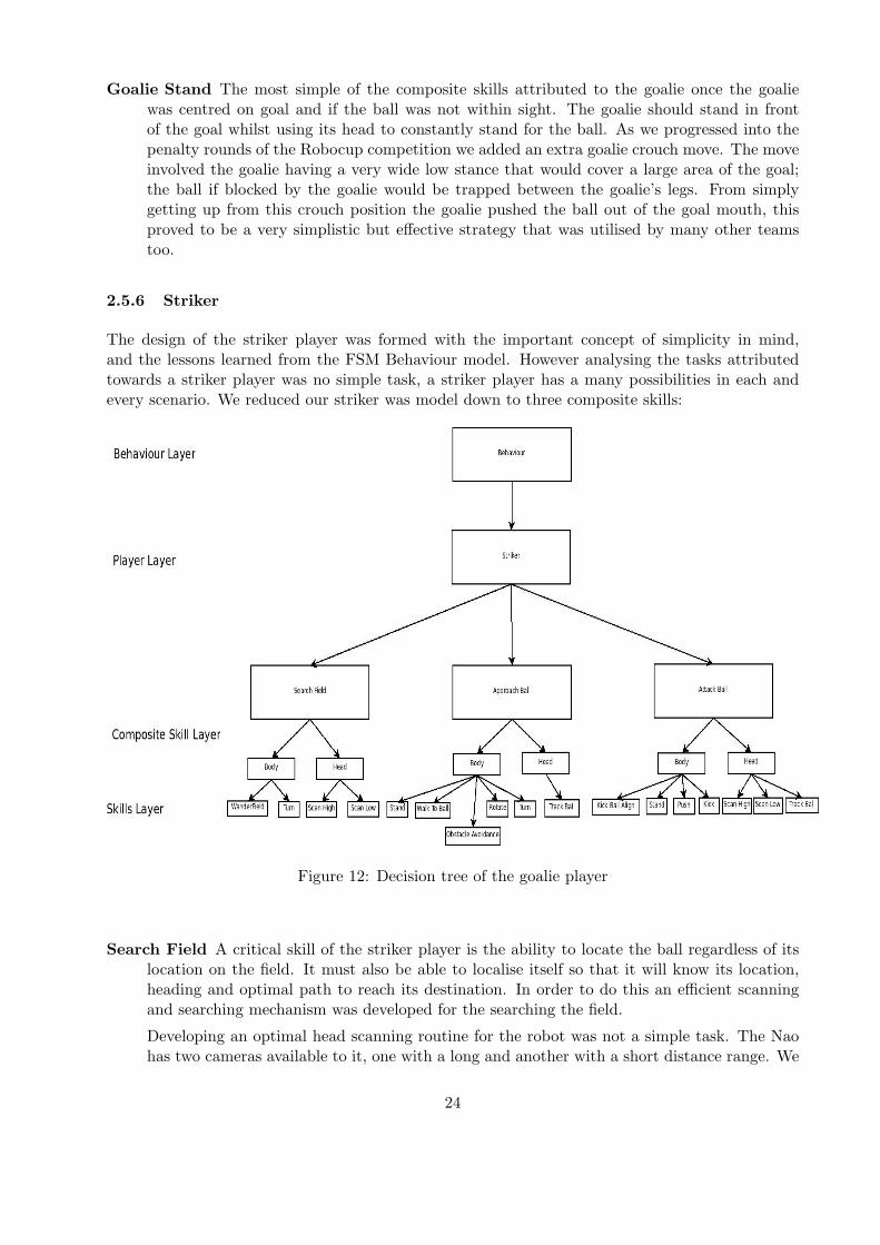
2.5.6 Striker
The design of the striker player was formed with the important concept of simplicity in mind,and the lessons learned from the FSM Behaviour model. However analysing the tasks attributedtowards a striker player was no simple task, a striker player has a many possibilities in each andevery scenario. We reduced our striker was model down to three composite skills:
Figure 12: Decision tree of the goalie player
Search Field A critical skill of the striker player is the ability to locate the ball regardless of itslocation on the field. It must also be able to localise itself so that it will know its location,heading and optimal path to reach its destination. In order to do this an efficient scanningand searching mechanism was developed for the searching the field.
Developing an optimal head scanning routine for the robot was not a simple task. The Naohas two cameras available to it, one with a long and another with a short distance range. We
24

encompassed both cameras into our scanning routine that allowed the robot to scan the fieldmore throughly, whilst also enabling it to better track the ball once found. Another problemfaced was the latency between the time commands that are sent to the head and the rate atwhich such commands can be processed. If commands are sent too rapidly, the head cannotcomplete each command resulting in a very jerky head scan. This caused the images takenfrom the camera to be blurred and impacted drastically on the robot’s ability to see the balland other landmarks. To overcome this, a PID controller is used to smoothly couple headcommands with the actual head movement routines.
Our optimal head scanning technique involved using the short distance camera first, to see ifthe ball was within close proximity. The head would scan from left to right and then right toleft covering field of vision that spanned 120 degrees. If the ball was not seen then the headpitch would be raised to 25 degree and vision would be signaled to utilise the top camera.The switching of cameras had the ability to generate a blind spot, however this was overcomeby utilising our optimal head pitch angle that would make sure the two images seen by thetwo different camera interlaced. The head would then scan from left to right in two sweepscovering a field of vision of 120 degrees.
With an optimal head scanning routine an efficient field roaming routine was required inorder to scan the field in the most efficient manner. This routine had to be able to cover thelargest area of field within the shortest possible amount of time whilst still being able detectthe ball, as speeding up the walk compromised sharpness of an image taken from the camera.
The best results from the head scanning routine came when the robot’s body was stationary;hence from this idea we developed a efficient body scanning routine to compliment the headscanning routine. The robot would rotate on the spot stopping every 90 degrees to allowthe head to scan the part of the field, while our head scanning routine had a field of visionof 120 degrees which meant that we could turn on the spot every 120 degrees instead of 90degrees, it was discovered that scanning towards the extreme left or right of the robot (yawof 60 or -60 degrees) the vision was impeded by the robot’s shoulder. Hence we built in a bitof redundancy to assure the whole field is scanned.
We combined these optimal scanning routines and used them to scan the whole field efficientlyand quickly. Despite vast improvements to our vision module our robot was still not able tosee the ball if it were close to a field length distance away, this meant that there were caseswhere despite scanning the whole field the robot will still not see the ball, we created a skillcalled wander field specifically for this worst case scenario.
Wander field attempts to return to the centre of the field and scan 360 degrees to pick up theball, as our vision module was able to pick up the ball reliably from a distance of half a fieldlength. However due to the lack of a reliable localisation module and self world model for therobot, this skill never worked very well.
Approach Ball This composite skill is responsible for getting the robot within a close range ofthe ball and facing the right direction towards goal. When the ball was seen the robot wouldimmediately jump to this composite skill, this meant that this composite skill dealt with bothlong range and close range methods of approaching the ball. The head would constantly trackthe ball, if the ball was far away the top camera would be used and if close it would switchto the bottom camera and vice versa.
This composite skill had different functionalities depending on the distance of the ball. Ifthe ball was far away its main goal was to approach the ball as quickly as possible, this wasachieved through setting the gait engine to it’s maximum speed and only using turn skills toalign the robot to the ball. The location and heading of the robot is ignored.
25

As soon as we are within proximity of the ball the robot begins to localise in preparation toscore a goal. The top camera is used to pans for a goal and obtains a rough heading andlocation of the robot. The robot then attempts to align itself, the ball, and the opponent’sgoal. The worst case scenario occurs when the robot is facing its own goal, in which case itmust promptly rotate around the ball, getting behind it and facing the opponent goal.
Attack Ball Once aligned, the robot can enter an attacking composite skill. The purpose of thiscomposite skill is to keep the robot aligned during the final approach to the ball and then eitherkick or push the ball into the goal. To achieve this a we utilised a player that would switchfrom kicking and pushing based on the distance from the opponent goal. During our friendlymatches against Newcastle University, we discovered for the Robocup world Championshipsjust kicking the ball in the right direction yielded better results. Kicking the ball in the rightdirection however requires very accurate ball distance and heading, as a slight deviation willkick the ball off at an angle. The lack of accurate measurements caused many issues with ourall distance calculation function, but through experimentation it was discovered that takingraw data straight from the vision module, rather than through localisation, yielded excellentand accurate results when within close proximity to the ball. Hence once the robot was closeenough to kick the ball, it would switch from reliance on localisation data to raw vision data.
In order for the robot to effectively kick a ball one of its two feet must be aligned (within+-12 degrees relative to the robot’s body) with the ball in kicking distance. Speed wasanother critical factor, the ability to align quickly and kick was very important. However,if we increased the speed of the robot’s gait as it was trying to align to the ball, the robotwould on many occasions overshoot its target and walk into the ball, tapping it forwards.The robot would then have to realign itself to the ball once more, reducing the effectivenessof the skill. Through experimentation we discovered that the most effective speed to alignbehind the ball was 20 percent of its maximum speed (16cm/s).
2.5.7 Conclusion
This new Behaviour architecture was a huge improvement on the old Behaviour architecture. Com-plexity was well distributed through the different layers of the decision tree, which led to morestructured code that was easier to debug. Whilst this behaviour was able to function and meet itsrequirements, there were several flaws within its architecture that can be further improved.
One of the key issues faced was the lack of a scheduler. Skills would run, but it was impossible toexplicitly set one skill to follow the next. A prime example of this is when the robot kicks for goal.We want the robot to look up to confirm that it can see the opponent’s goal and then kick theball. However once we look up for the goal the decision tree will think that we have lost the balland enter a search for ball routine. In this situation we should be able to force the decision treeto commit to the kick skill. To solve this, a local blackboard within behaviour was created whichallowed state to be shared amongst the different tiers of the decision tree, however this wasn’t avery elegant solution and reintroduced the problems inherent of the FSM.
Communication between the head and body skills was vastly improved as the composite layerfacilitated the sharing of data between the two skills. Despite this the behaviour module alsosuffered greatly due to shortfalls of other modules, particularly localisation.
A lack of an accurate ball distance function led to a lot of issues within the behaviour module. Skillswere based on thresholds that were derived through trial and error, rather than accurate distancereadings. The kicking skill was also very difficult to develop utilising the provided ball distance. It
26

was not until we switched to raw vision data that this issue was solved. This year’s competitionwas played with a basic goal heading value and no other reliable data from localisation; this meantthat the robot had no world model or reliable sense of self-position. The sharing of world modelsbetween robots and the development of team strategies with complex skills was not possible dueto these shortcomings. However, considering our skill set the behaviour performed very well in thecompetition despite its flaws.
3 Competition In Graz
The 2009 Robocup Symposium took place in Graz, Austria. We were among 25 teams from aroundthe world competing in the Standard Platform League, the league which uses the Nao robot fromAldebaran with no hardware modifications.
We were placed into Pool D which consists of three teams in a round robin:
• rUNSWift (UNSW, Australia)
• ZaDeAt (Knowledge-Based Systems Group, RWTH Aachen University, Germany; Institutefor Software Technology, Graz University of Technology, Austria, Agents and Robotics Re-search Lab, University of Cape Town, South Africa)
• Mousqetaires (Laboratory of System Engineering, Versailles University, France)
The following is adapted from an email sent by Mr Brad Hall to the CSE community when we hadfinished competing:
Our first game was against ZaDeAt, which was problematic due to a colour calibrationproblem in the first half. In the second half we were also still having calibration problemsand kicked the ball out a lot. However, we kept possession most of the game and soalthough we were unable to score, we kept it to a 0-0 draw.
In the second game against Les 3 Mousquetaire we also had possession most of thegame. At one kick-off we scored immediately, however, this is not allowed (the ballmust leave the circle before a goal can be scored by the attackers). We had a few moreclose goals before we fumbled the ball and left it near our goal without a defender, andLes 3 Mousquetaire were able to score. However, with just 5 seconds remaining on theclock, we were able to get a goal in and equalized the game. There are no penaltyshoot-outs in the first pool games, so it was a 1-1 draw.
Later, Les 3 Mousquetaire won a game against ZaDeAt 1-0, so we came second in ourpool.
Second and third teams then proceed to an Intermediate Round, where we came upagainst TJ Ark from the School of Electronics and Information, Tongji University,China. This game ended in a 0-0 draw, but in this round, draws lead to a penaltyshoot-out. There were 5 attempts at goal for each team, and unfortunately, the Chinesescored after the third, and we were not able to equalise, so we were knocked out of thecompetition.
Following our being knocked out of the soccer competition, we spent our remaining time in Austriadeveloping code for some of the ‘challenge’ competitions. Each year at Robocup, a number of
27

challenges are put forward, with the aim of rapidly advancing the level of innovation found inRobocup software.
rUNSWift 2009 entered in the Any Ball Challenge, the Passing Challenge and the LocalisationChallenge. We will describe our entry into the former two in detail:
3.1 Any Ball Challenge
So far in the history of Robocup, ball detection has relied heavily on the precise specifications ofthe ball, in particular colour information, but also the size, weight and texture. The Any BallChallenge aimed to move towards the development of ball detection software that did not rely onthese strict specifications.
The challenge required participants to locate a number of previously unseen balls on the field, andkick as many of them as possible into the goals. Points were awarded for making contact with theball, and further points were added if a goal was scored.
To participate in this challenge, the rUNSWift 2009 team developed custom image recognitionroutines and behaviours.
3.1.1 Vision
From a vision point of view, the any ball challenge was interesting because it proved that usefulinformation could be extracted from an image by considering only two symbolic colours, green andnon-green. The process used relied on the opencv circular hough transform for detecting circles.The ‘any ball’ image is first converted to black and white, with all green pixels being black, and allother pixels being white. A large Gaussian blur is then applied to smooth over any noise causedby the rough edges. This is highly CPU intensive, and if this step can be removed, a houghtransform should be able to be performed in real time. Once blurred, cvHoughCircles was used tofind potential balls in the image. The sanity checks were then run on each candidate ball to weedout false positives, caused by other curves on the field such as the centre circle. (See Appendix E)
3.1.2 Behaviour
The downfall of our performance in the Any Ball Challenge was our inability to develop suitablebehaviour code in time for the contest. The Any Ball Challenge exposed an inherent weakness inthe design of many parts of our behavioural system.
Many of the simple operations behaviour would perform, such as walking to a particular point,performing a kick, or looking around, were conducted as follows:
1. Set counter to 0, and issue command to locomotion
2. Each run of behaviour, increment counter until it reaches threshold
3. Once threshold is reached, assume command is complete
Due to the use of these thresholds, it was necessary to tweak the behavioural constants every timea performance enhancement was made elsewhere.
28

Figure 13: The any ball algorithm applied in two stages, blurring and then circular hough transform
29

This became particularly prevalent, when the more advanced, but slower vision module was usedfor the Any Ball Challenge, resulting in all behaviours not functioning correctly due to havingthresholds that are too large.
Our attempt at solving this problem was to perform some simple arithmetic: Since the Any BallVision was 8 times slower than regular vision, all constants in Behaviour were divided by 8. This didnot seem to work correctly, since there is a non-linear relationship between each of these constants,and as a result we were unable to perform in the Any Ball Challenge.
This problem could easily be solved if the locomotion module provided information on the Black-board about when these sorts of events have finished, then Behaviour can subscribe to the loco-motion state using the Blackboard Hooks (Section 2.1), and not need to rely on fiddly timingconstants.
3.2 Passing Challenge
3.2.1 Background
This year’s Robocup challenge signified a big skill jump from last year’s league, many teams whocompleted were capable of scoring multiple goals and having quite complex strategies. This year’scompetition also saw reinstatement of Robocup challenges within the SPL league, the purpose ofthese challenges is to push the envelope of the league, robotics and AI. This chapter will focus onthe passing challenge of the 2009 Robocup World Championships SPL league.
3.2.2 Requirements
This year’s passing challenge was adapted from last year’s humanoid league; it involves two robotson either side of the field having to pass the ball between them. The ball was not allowed to leavethe field and a buffer zone was set in the middle of the field where the robots could not enter.The purpose of this challenge was to develop a team passing strategy, and investigate the idea ofactual team play. As within the competition passing was actually quite rare and a very difficulttask to achieve, this challenge presented a small subset of this problem. The robots had 2 minutesto perform 3 successive passes between them.
3.2.3 Limitations!
Our main focus throughout our lead up to the competition was the actually soccer competitionitself, so we had not given the challenges much thought at all. However unfortunately we wereeliminated quite early in the soccer competition hence we chose then to focus our energy on thechallenges.
The design of the new Behaviour module made it very easy to create a new player class based onpre-existing skills, lining up and kicking the ball skills had already been implemented. The currentexisting kick on the robot was too powerful though it would always result in the ball being kickedout of the field, hence we had to tune down the power of the kick whilst still keeping the robotstable.
Localisation was another key factor that was required for this challenge; with the localisation thatwas available at the time we had no reliable world model or self positioning on the field hence it
30

Figure 14: Set up of field for the passing challenge [2]
became very difficult to find a solution to the passing challenge, however lucky we had a somewhatreliable opponent goal heading.
3.2.4 Our Approach
The ideal solution to this problem would be to have an accurate localisation, team communicationand field line detection. Utilising the localisation data one robot could then communicate to theother robot as to which role it is (passer or receiver) and which direction/heading the ball wouldbe going towards. Using field lines detection would guarantee the ball would not leave the field andthe robots would not stray into the buffer zone.
However with our current codebase this ideal solution was not possible as we lacked an accuratelocalisation and field line detection. We had a robot communication module but without an accuratelocalisation there was not much sense in communicating between the two robots. Analysing ourlimitation we came upon a nave solution to solve the passing challenge, factoring in the time inwhich we had to develop a solution was also critical, namely 1 day.
Both robots would be assigned the pass or receiver role, rather than having this communicatedbetween the two robots we decided that this should be based on the return value of the balldistance function when the ball was in sight. Taking into account the field size, goal box and thebuffer zone we set this ball distance threshold to 1.5m. If the robot was greater than 1.5m fromthe ball it would assume the receiver role, if the robot was less than 1.5m it would be passer.
The passer’s role was to try to pass the ball, utilising the our tuned down kick, towards the centreof its opponent goal where the receiver will be standing and tracking the ball. Once the ball isoutside of the 1.5m ball distance threshold of the passer it will switch to the receiver role and vice
31

versa for the receiving robot. The passer utilised skills that we developed for the soccer competitionnamely approaching the ball, aligning itself to kick in the right goal, and aligning itself to kick.This was a huge advantage that our new behaviour architecture allowed, we were able to rapidlydevelop and test this role within one day.
The receiver’s role is much more simplistic, it simply needs to track the ball and be ready to receiveand switch roles to a passer as the ball comes closer to it. However it needed to allow itself to bein the best field position to receive, the first approach that was utilised was to get the receiver toreturn to the centre of goal after it has passed the ball and switched to the receiver role. But dueto a lack of a reliable localisation we weren’t able to return to the centre of goal, with this setbackanother method was devised. This time utilising the crouch of the goalie, this stance allowed for awide coverage of area which increased our chances of catching the ball and then quickly returningit to the other robot. This method had one flaw though the goalie crouch took a very long timeto stand up from, with a 2 minute time constraint this was no a possible solution. Due to timeconstraints we chose to go with no way of optimising the receiver’s position.
In order to avoid the robots entering the buffer zone in the centre of the field, due to a lack of fieldline detection we simply made sure that our kick was strong enough to away go beyond the bufferzone but not outside of the field.
3.2.5 Results
During initial testing of our solution to the passing challenge we were able to get the robot to passbetween themselves at least 2 times, whilst this solution was somewhat simplistic and naive forthe time constraints and the demands of the competition it had achieved its purpose. However aswe are all students of Murphy’s Law during the actual run of the passing challenge our robot hadfallen over which heavily skewed its localisation goal heading data resulting in the robot kickingthe ball outside of the field of play.
Another run was done after this official run and the robot were able to pass between themselvesthrice; the irony of the situation is that was the best performance achieved within the league.Overall no teams were able to achieve passing it their official runs; hence there was no winner inthis challenge.
3.3 Lessons Learned
Our entry at the 2009 Robocup Symposium highlighted a few aspects of writing software for theNao platform that require particular attention if we are to be more competitive in future years:
Robust Vision Our vision system needs to become less dependent on colour segmentation, andbe able to deal with greater variance in lighting conditions.
Accurate Localisation Not having an accurate world model had a crippling effect on our abilityto play soccer. This module needs to be addressed as a priority.
High Level Behaviours It must be possible to represent behaviours in a high-level format, toallow for more rapid prototyping. The output of the behaviour module should not depend onthe runtime performance of other modules.
Unit Testing & Integration Testing A higher emphasis has to be given to writing tests forevery class developed for the rUNSWift broker. Last-minute code changes with no regression
32

test suite caused some disastrous issues when playing games. Furthermore, all modules mustbe tested together, on the robot, highly frequently. With a full-time team, it should be arequirement that the nightly ‘master’ build be tested on the robots at the start of each dayof work. Then fixing bugs should be giving priority over any new development.
Debugging Tools rUNSWift needs an integrated suite of debugging utilities that allow problemswith vision, localisation and behaviours to be detected and diagnosed rapidly. These toolsneed to have the ability to log all data processed by the robot so that errors can be reproducedoff-line.
33

Bibliography
References
[1] Adam Brimo. COMP3902: Special Project B Report: Robocup 2008, 2008.
[2] RoboCup SPL Technical Committee. Technical Challenges for the RoboCup 2009 StandardPlatform League Competition, 2009.
[3] Gary Huynh. Special Project A Report: Robocup SPL League, 2008.
[4] Alex North. Object recognition from sub-sampled image processing, 2005.
34

A Blackboard.hpp
#ifndef BLACKBOARD HPP#define BLACKBOARD HPP
using namespace std ;
#ifde f BLACKBOARDHOOKSenum OperationHook{READ HOOK, WRITE HOOK, NUM OPERATION HOOK TYPES} ;enum TimingHook {PRE HOOK , POST HOOK , NUM TIMING HOOK TYPES} ;#endif
/∗∗∗ Macro wrapping the push o f <code>va lue </code> to <code>queue</code>∗ on the b l ackboard .∗∗ @param queue the queue o f the b l ackboard be ing wr i t t en to∗ @param va lue the va lue to be pushed∗/
#define pushToBlackboardQueue ( queue , va lue ) \blackboard . wr i t e (&blackboard . queue , va lue )
/∗∗∗ Macro wrapping the wr i t e o f <code>va lue </code> to <code>component</code>∗ on the b l ackboard .∗∗ @param component the component o f the b l ackboard be ing wr i t t en to∗ @param va lue the va lue to be wr i t t en∗/
#define valueToBlackboard ( component , va lue ) \blackboard . wr i t e (&blackboard . component , va lue )
/∗∗∗ Macro wrapping the wr i t e o f <code>count</code> b y t e s from <code>fd</code> to∗ <code>component</code> on the b l ackboard .∗∗ @param component the component o f the b l ackboard be ing wr i t t en to∗ @param fd f i l e d e s c r i p t o r to be wr i t t en from∗ @param count number o f b y t e s to be wr i t t en∗ @return number o f b y t e s a c t u a l l y wr i t t en∗/
#define fDToBlackboard ( component , fd , count ) \blackboard . wr i t e (&blackboard . component , fd , count )
/∗∗∗ Macro wrapping a read o f <code>component</code> o f f the b l ackboard .∗∗ @param component the component o f the b l ackboard be ing read from∗ @return the va lue o f <code>component</code>∗/
#define readFromBlackboard ( component ) \blackboard . read (&blackboard . component )
/∗∗∗ Macro wrapping a pop o f <code>queue</code> o f f the b l ackboard .∗∗ @param queue the queue o f the b l ackboard be ing pop from∗ @return the va lue pop from <code>queue</code>∗/
35

#define popFromBlackboardQueue ( queue ) \blackboard . read(&blackboard . queue )
#ifde f BLACKBOARDHOOKS/∗∗∗ Macro wrapping the adding o f a hook <code>func t ion </code> to∗ <code>component</code >.∗ @param component the component o f the b l ackboard be ing hooked∗ @param func t i on the hook be ing added . must be o f type vo id (∗) ( vo id ∗) ,∗ where the func t i on parameter w i l l be a vo id ∗ to∗ <code>component</code>∗ @param operationHook opera t ion o f hook (READ HOOK or WRITE HOOK)∗ @param timingHook t iming o f hook (PRE HOOK or POST HOOK)∗ @return the va lue o f <code>component</code>∗/
#define addHookToBlackboard ( component , funct ion , operationHook , timingHook ) \blackboard . addHook(&blackboard . component , funct ion , operationHook , \
timingHook ) ;#endif
/∗∗∗ Stores a l l shared data .∗ Also prov i de s hook f u n c t i o n a l i t y∗/
class Blackboard{#ifde f BLACKBOARDHOOKS
private :/∗∗∗ The hash t a b l e t h a t s t o r e s the hooks f o r any o f the data t ype s on the∗ b l ackboard .∗ A 2x2 array o f h a s h t a b l e s mapping from components to a s e t o f f unc t i on s .∗/
map<pointer , vector<void (∗ ) (void ∗)> > hooks [NUM OPERATION HOOK TYPES][NUM TIMING HOOK TYPES ] ;
#endifpublic :
/∗∗∗ Blackboard Constructor . Respons i b l e f o r i n i t i a l i s i n g ALL v a r i a b l e s .∗ Update t h i s cons t ruc t o r as i tems are added to the b l ackboard .∗ The v a r i a b l e s shou ld be i n i t i a l i s e d to something meaningfu l to the∗ module r e t r i e v i n g the v a r i a b l e s data∗ NOTE: Any o b j e c t s s t o r ed on the b l ackboard are assumed to have t h e i r∗ con ten t s i n i t i a l i s e d v ia t h e i r d e f a u l t con s t ruc t o r∗/
Blackboard ( ) ;
/∗∗∗ Cleans up memory a l l o c a t e d by the cons t ruc t o r∗/
˜Blackboard ( ) ;
/∗∗∗ Pop <code>component</code>from the b l ackboard <code>queue</code >.∗ Ca l l s pre and pos t read hooks , i f s e t∗∗ @param queue the queue to be popped∗ @return r e f e r ence o f type <code>component</code> to the data from∗ <code>queue</code>
36

∗/template <class T>const T read ( ConcurrentQueue<T> ∗queue ) ;
/∗∗∗ Read <code>component</code> from the b l ackboard .∗ Ca l l s pre and pos t read hooks , i f s e t∗∗ @param component the data to be read∗ @return po in t e r o f type <code>component</code> to the data in∗ <code>component</code>∗/
template <class T>const T ∗ read ( const T ∗component ) ;
/∗∗∗ Write <code>count</code> b y t e s from <code>fd</code> to∗ <code>component</code> in the b l ackboard .∗ Ca l l s pre and pos t wr i t e hooks , i f s e t∗∗ @param component l o c a t i o n to be wr i t t en to∗ @param fd f i l e d e s c r i p t o r be ing wr i t t en from∗ @param count number o f b y t e s to be wr i t t en∗ @return number o f b y t e s a c t u a l l y wr i t t en∗/
template <class T>s s i z e t wr i t e (T component , int fd , s i z e t count ) ;
/∗∗∗ Push <code>va lue </code> to <code>component</code> in the b l ackboard .∗ Ca l l s pre and pos t wr i t e hooks , i f s e t∗∗ @param queue queue to be wr i t t en to∗ @param va lue va lue to be wr i t t en∗/
template <class T>void wr i t e ( ConcurrentQueue<T> ∗queue , const T &value ) ;
/∗∗∗ Write <code>va lue </code> to <code>component</code> in the b l ackboard .∗ Ca l l s pre and pos t wr i t e hooks , i f s e t∗∗ @param component l o c a t i o n to be wr i t t en to∗ @param va lue va lue to be wr i t t en∗/
template <class T>void wr i t e (T ∗component , const T &value ) ;
#ifde f BLACKBOARDHOOKS/∗∗∗ Ca l l a l l hooks on <code>key</code >.∗∗ @see doHook∗ @param key po in t e r to the data l o c a t i o n be ing hooked∗ @param operationHook f l a g opera t ion f o r hook (READ HOOK, WRITE HOOK)∗ @param timingHook f l a g t iming o f hook (PRE HOOK or POST HOOK)∗ @return <code>true </code> i f s u c c e s s f u l ,∗ <code>f a l s e </code> o therw i s e ( e . g . i f the <code>key</code> i s∗ i n v a l i d )∗/
37

// temp la te <c l a s s T>void ca l lHooks (void ∗key , OperationHook operationHook ,
TimingHook timingHook ) ;
/∗∗∗ Add a hook on <code>key</code >.∗∗ @param key po in t e r to the data l o c a t i o n be ing hooked∗ @param func t i on a po in t e r to the hook funct ion , which t a k e s as i t s∗ s i n g l e parameter the <code>component</code> i t i s∗ hooking . I t i s r e s p on s i b l e f o r i t s own s e l f −conta ined∗ error r epo r t i n g∗ @param operationHook f l a g opera t ion f o r hook (READ HOOK, WRITE HOOK)∗ @param timingHook f l a g t iming o f hook (PRE HOOK or POST HOOK)∗ @return <code>true </code> i f s u c c e s s f u l ,∗ <code>f a l s e </code> o therw i s e ( e . g . i f the <code>key</code> i s∗ i n v a l i d )∗/
// temp la te <c l a s s T>bool addHook (void ∗key ,
void (∗ f unc t i on ) (void ∗) ,OperationHook operationHook ,TimingHook timingHook ) ;
#endif
/∗∗∗ Lock , increment a counter , s i g n a l and r e l e a s e l o c k on a cond i t i on∗ v a r i a b l e . This i s used f o r thread synchron i sa t i on . Whenever t h i s∗ f unc t i on i s c a l l e d , counter increments by 1 and whenever the wa i t ing∗ thread proce s s e s the data the counter i s r e s e t to 0 .∗ @param cond i t i onVar i a b l e the cond i t i on v a r i a b l e s t r u c t to be∗ operated on .∗ @see waitOnCondit ionVariab le∗/
void s igna lThread ( Condi t ionVar iab le& cond i t i onVar i ab l e ) ;
/∗∗∗ macro to make i t l ook l i k e e v e r y t h in g e l s e in b l ackboard∗/
#define s ignalWait ingThread ( component ) \blackboard . s igna lThread ( blackboard . component )
/∗∗∗ Lock , wait , r e s e t counter and unlock on a cond i t i on v a r i a b l e . This∗ i s used by a wa i t ing thread such as Behaviour∗/
void waitOnVariable ( Condi t ionVar iab le& cond i t i onVar i ab l e ) ;
#define waitOnCondit ionVariable ( component ) \blackboard . waitOnVariable ( blackboard . component )
/∗∗∗ Unlock the mutex . This shou ld on ly be used in the d e s t r u c t o r o f∗ c l a s s e s to ensure t ha t i t i s not dead l ock ing the system .∗ @param cond i t i onVar i a b l e the cond i t i on v a r i a b l e∗/
void unlock ( Condi t ionVar iab le& cond i t i onVar i ab l e ) ;
#define tryUnlock ( component ) \blackboard . unlock ( blackboard . component )
38

/∗∗ From t h i s po in t on , d e f n i t i o n s f o r v a r i a b l e s on the Blackboard are∗ dec l a r ed . Omitted here f o r b r e v i t y .∗/
} ;
#include ”Blackboard . t c c ”
extern Blackboard blackboard ;
#endif
39

B SanityChecks.cpp
#include <s t d i o . h>
#include <blackboard /Blackboard . hpp>#include ”SanityChecks . hpp”#include ”SanityConstant . hpp”#include ”Vis ionDef . hpp”#include ”DebugDraw . hpp”#include ”LeastSquaresLine . hpp”
#undef MAX#undef MIN
#define MAX(a , b) ( ( ( a ) > (b) ) ? ( a ) : (b) )#define MIN(a , b) ( ( ( a ) < (b) ) ? ( a ) : (b) )
stat ic In san i ty ba l l S i z eTe s t ( const Visua lObject &ba l l ) ;stat ic In san i ty bal lOrangeTest ( const Visua lObject &ba l l ) ;
stat ic In san i ty san i t i z eGoa lPos t ( const GoalObject &goal , Color c o l o r ) ;stat ic In san i ty postColourTest ( const GoalObject &goal , Color c o l o r ) ;
/∗∗∗ The b a l l co lour t e s t e r w i l l check p i x e l s∗ ( rad ius / BALL COLOUR DENSITY)∗ p i x e l s apar t∗/
#define BALL COLOUR DENSITY 5
/∗∗∗ Percent o f b a l l rad ius to s k i p as edge∗/
#define BALL COLOUR EDGE SKIP PERCENT 20
/∗∗∗ Maxium edge s i z e to be sk ipped∗/
#define BALL COLOUR EDGE SKIP MAX 5
/∗∗∗ Percent o f orange p i x e l s which must be conta ined∗ wi th in the b a l l f o r i t not to be i n v a l i d a t e d∗/
#define BALL COLOUR ORANGE PERCENT 70
/∗∗∗ Percent o f robo t p i x e l s which must be conta ined∗ wi th in the b a l l f o r i t to be i n v a l i d a t e d∗/
#define BALL COLOUR ROBOT RED PERCENT 20
/∗∗∗ Percent o f y e l l ow goa l p i x e l s which must be conta ined∗ wi th in the b a l l f o r i t to be i n v a l i d a t e d∗/
#define BALL COLOUR YELLOW GOAL PERCENT 20
/∗∗∗ The goa l co lour t e s t e r w i l l check p i x e l s
40

∗ ( goalWidth / BALL COLOUR DENSITY / 2)∗ p i x e l s apar t∗/
#define GOAL COLOUR DENSITY 10
/∗∗∗ Percent o f goa l width to s k i p as edge∗/
#define GOAL COLOUR EDGE SKIP PERCENT 20
/∗∗∗ Maxium edge s i z e to be sk ipped∗/
#define GOAL COLOUR EDGE SKIP MAX 5
/∗∗∗ Percent o f goa l p i x e l s which must be conta ined∗ wi th in the b a l l f o r i t not to be i n v a l i d a t e d∗/
#define GOAL COLOUR COLOUR PERCENT 70
/∗∗∗ Max diameter o f b a l l when us ing the bottom camera∗/
#define BALL SIZE BOTTOM MAX
/∗∗∗ Max diameter o f b a l l when us ing the top camera∗/
#define BALL SIZE TOP MAX
#define STRONG GOAL MIN WIDTH 10#define STRONG GOAL MIN HEIGHT 50
#define STRONG GOAL MIN SCANLINES 6
#define STRONG GOAL AUTO SCANLINES 10
#define STRONG GOAL PAIR WIDTH TOL PERC 30
In san i ty san i t i z eB lueGoa lPos t ( const GoalObject &post ){
return s an i t i z eGoa lPos t ( post , cBEACON BLUE) ;}
In san i ty san i t i z eYe l l owGoa lPos t ( const GoalObject &post ){
return s an i t i z eGoa lPos t ( post , cBEACON YELLOW) ;}
In san i ty san i t i z eGoa lPos t ( const GoalObject &post , Color c ){
In san i ty r e t ;i f ( ( r e t = postColourTest ( post , c ) ) != SANE) {
return r e t ;}return SANE;
}
In san i ty postColourTest ( const GoalObject &post , Color c o l o r )
41

{/∗ i f t he goa l ang led more than 45 degrees i t s insane ∗/const LeastSquaresLine &l = post . mid ;i f ( ! l . isAbsSlopeGT1 ( ) ) {
return GOAL TOO SLANTED;}
int x , y ;int xstar t , y s tar t , xend , yend ;int goa lP i x e l s = 0 , t e s t ed = 0 ;
int edgeSkip = MIN (GOAL COLOUR EDGE SKIP MAX,(GOAL COLOUR EDGE SKIP PERCENT ∗ post . aveWidth ) / 100 + 1) ;
int testWidth2 = ( post . aveWidth − edgeSkip ) / 2 ;
int s tep = ( testWidth2 / GOAL COLOUR DENSITY) + 2 ;
y s t a r t = MAX (IMAGE EDGE, post . bb y ) ;yend = MIN (BASIC HEIGHT − IMAGE EDGE, post . bb endy ) ;for ( y = ys t a r t ; y < yend ; y += step ∗ 3) {
int cx = l . predictX (y ) ;x s t a r t = MAX (IMAGE EDGE, cx − testWidth2 ) ;xend = MIN (BASIC WIDTH − IMAGE EDGE, cx + testWidth2 ) ;for ( x = xs t a r t ; x < xend ; x += step ) {
DEBUG DRAW PIXEL (x , y , 82 , 91 , 240) ;Color c = CorrectedImage : : c l a s s i f y (x , y ) ;i f ( c == co l o r ) {
DEBUG DRAW PIXEL (x , y , 105 , 78 , 64) ;g o a lP i x e l s ++;
}t e s t ed ++;
}}
// p r i n t f (” goa l %d %d %d %d %d\n” , testWidth2 , edgeSkip , s tep , g oa lP i x e l s ,t e s t e d ) ;
i f ( t e s t ed == 0) {return SANE;
}i f ( ( g o a lP i x e l s ∗ 100 / t e s t ed ) < GOAL COLOUR COLOUR PERCENT) {
// p r i n t f (” Post i n v a l i d a t e d : not co loured enough\n”) ;return GOAL NOT MUCH COLOUR;
} else {return SANE;
}}
In san i ty s a n i t i z eB a l l ( const Visua lObject &ba l l ){
In san i ty r e t ;i f ( ( r e t = ba l l S i z eTe s t ( b a l l ) ) != SANE) {
return r e t ;} else i f ( ( r e t = bal lOrangeTest ( b a l l ) ) != SANE) {
return r e t ;}return SANE;
}
42

In san i ty ba l l S i z eTe s t ( const Visua lObject &ba l l ){
return SANE;}
In san i ty bal lOrangeTest ( const Visua lObject &ba l l ){
int x , y ;int xstar t , y s tar t , xend , yend ;int orange = 0 , robotRed = 0 , ye l low = 0 , t e s t ed = 0 ;
int edgeSkip = MIN (BALL COLOUR EDGE SKIP MAX,(BALL COLOUR EDGE SKIP PERCENT ∗ ba l l . r ad iu s ) / 100 + 1) ;
int testRad = ba l l . r ad iu s − edgeSkip ;int s tep = ( testRad / BALL COLOUR DENSITY) + 1 ;
i f ( testRad <= 0) {return SANE;
}
int testRad2 = testRad ∗ testRad ;
x s t a r t = MAX (IMAGE EDGE, b a l l . cx − testRad ) ;y s t a r t = MAX (IMAGE EDGE, b a l l . cy − testRad ) ;xend = MIN (BASIC WIDTH − IMAGE EDGE, b a l l . cx + testRad ) ;yend = MIN (BASIC HEIGHT − IMAGE EDGE, b a l l . cy + testRad ) ;
for ( x = xs t a r t ; x < xend ; x += step ) {for ( y = ys t a r t ; y < yend ; y += step ) {
/∗∗∗ Check t ha t the po in t i s w i th in the b a l l∗/
int rx = (x − ba l l . cx ) ;int ry = (y − ba l l . cy ) ;i f ( rx ∗ rx + ry ∗ ry <= testRad2 ) {
DEBUG DRAW PIXEL (x , y , 82 , 91 , 240) ;Color c = CorrectedImage : : c l a s s i f y (x , y ) ;i f ( c != cWHITE) {
i f ( c == cBALL) {DEBUG DRAW PIXEL (x , y , 105 , 78 , 64)
;orange ++;
}i f ( c == cBEACON YELLOW) {
ye l low ++;}i f ( c == cROBOT RED) {
robotRed ++;}t e s t ed ++;
}}
}}
// p r i n t f (” b a l l %d %d %d %d %d %d %d\n” ,// testRad , edgeSkip , s tep , orange , robotRed , ye l low , t e s t e d ) ;i f ( t e s t ed == 0) {
return SANE;
43

}i f ( ( orange ∗ 100 / t e s t ed ) < BALL COLOUR ORANGE PERCENT) {
// p r i n t f (” Ba l l i n v a l i d a t e d : not orange enough\n”) ;return BALL NOT MUCH ORANGE;
} else i f ( ( robotRed ∗ 100 / t e s t ed ) > BALL COLOUR ROBOT RED PERCENT) {// p r i n t f (” Ba l l i n v a l i d a t e d : too redd i sh \n”) ;return BALL TOO MUCH ROBOT RED;
} else i f ( ( ye l low ∗ 100 / t e s t ed ) > BALL COLOUR YELLOW GOAL PERCENT) {// p r i n t f (” Ba l l i n v a l i d a t e d : too y e l l ow i s h \n”) ;return BALL TOO MUCH GOAL YELLOW;
} else {return SANE;
}}
bool i s S t r ongS ing l ePo s t ( const GoalObject &post ){
i f ( post . l ineCount >= STRONG GOAL AUTO SCANLINES) {return true ;
}
i f ( post . aveWidth < STRONG GOAL MIN WIDTH) {return fa lse ;
}int he ight = post . bb endy − post . bb y ;i f ( he ight < STRONG GOAL MIN HEIGHT) {
return fa lse ;}i f ( post . l ineCount < STRONG GOAL MIN SCANLINES) {
return fa lse ;}return true ;
}
bool i sS t rongPos tPa i r ( const GoalObject &post1 , const GoalObject &post2 ){
int widthDi f fPerc = abs ( post1 . aveWidth − post2 . aveWidth ) ∗ 100 /( ( post1 . aveWidth + post2 . aveWidth ) / 2) ;
i f ( widthDi f fPerc < STRONG GOAL PAIR WIDTH TOL PERC) {return fa lse ;
}
return true ;}
void s an i t i z eGoa l I nBa l l ( FrameInfo &frameInfo ){
Visua lObject &ba l l = frameInfo . vob [ vobBal l ] ;Visua lObject &ye l low1 = frameInfo . vob [ vobYellowGoalPost1 ] ;Visua lObject &ye l low2 = frameInfo . vob [ vobYellowGoalPost2 ] ;
/∗ a l l ow ex t ra rad ius f o r goa l h e i g h t ∗/i f ( ye l low1 . he ight < ba l l . r ad iu s ∗ 3) {
int d i s t = hypot ( b a l l . cx − ye l low1 . cx , b a l l . cy − ye l low2 . cy ) ;/∗ a l l ow f o r two r a d i i between goa l ∗/i f ( d i s t < ba l l . r ad iu s ∗ 2) {
p r i n t f ( ”VISION : k i l l e d goa l in b a l l \n” ) ;ye l low1 . r e s e t ( ) ;
}
44

}
/∗ a l l ow ex t ra rad ius f o r goa l h e i g h t ∗/i f ( ye l low2 . he ight < ba l l . r ad iu s ∗ 3) {
int d i s t = hypot ( b a l l . cx − ye l low2 . cx , b a l l . cy − ye l low2 . cy ) ;/∗ a l l ow f o r two r a d i i between goa l ∗/i f ( d i s t < ba l l . r ad iu s ∗ 2) {
p r i n t f ( ”VISION : k i l l e d goa l in b a l l \n” ) ;ye l low2 . r e s e t ( ) ;
}}
}
45

C NaoCamera.hpp
#ifndef NAOCAMERA HPP#define NAOCAMERA HPP
/∗ ∗∗∗∗∗∗∗∗∗∗ v4 l headers ∗∗∗∗∗∗∗∗∗∗∗∗∗∗ ∗///#de f i n e USE V4L//#i f d e f USE V4L#include <sys / types . h>#include <sys / s t a t . h>#include < f c n t l . h>#include <sys / i o c t l . h>#include <uni s td . h>#include <l i nux / videodev2 . h>#define DEV VIDEO ”/dev/ video0 ”typedef enum {
IO METHOD READ,IO METHOD MMAP,IO METHOD USERPTR,IO METHOD FILE
} io method ;#define DEFAULT IO METHOD IO METHOD MMAP#define NUM FRAME BUFFERS 4//#end i f/∗ ∗∗∗∗∗∗∗∗∗∗ / v4 l headers ∗∗∗∗∗∗∗∗∗∗∗∗∗∗ ∗/
#ifndef OFFLINE#include <alproxy . h>#include <a l l ogge rp roxy . h>#endif#define YUV422 BYTES PER PIXEL 2
enum WhichCamera{whichCameraError = −1,topCamera = 0 ,bottomCamera = 1 ,numCameras = 2
} ;class NaoCamera {// : p u b l i c Camera {public :
/∗∗∗ Constructor∗ opens the dev ice , c a l i b r a t e s i t , and s e t s i t up f o r streaming∗/
NaoCamera( io method method = DEFAULT IO METHOD) ;
/∗∗∗ Destruc tor∗ c l o s e s the dev i c e∗/
virtual ˜NaoCamera ( ) ;
/∗∗∗ t e l l s the c a l l e d the co r r e c t image dimensions∗ @param width w i l l be s e t to the image ’ s width∗ @param he i g h t w i l l be s e t to the image ’ s h e i g h t∗ @return i f a co r r e c t format has been s e t∗/
virtual bool imgDimensions ( int& width , int& he ight ) ;
46

/∗∗∗ Get the image and conver t i t to yuv422 ( i f not na t i v e )∗ @return i f the image was f e t c h ed s u c c e s s f u l l y∗/
virtual bool getYUV422 ( ) ;
/∗∗∗ I f a pp l i c a b l e , changes the current camera be ing used . I f necesary ,∗ d i s a b l e s the v ideo stream momentarily so the stream can swi t ch inpu t s .∗∗ @param whichCamera s p e c i f i e s the top or bottom camera to sw i t ch to∗ @return whether the s e t succeeds∗ @s i d e e f f e c t s t op s captur ing , sw i t ch e s the camera , then s t a r t s again∗/
bool setCamera (WhichCamera whichCamera ) ;
/∗∗∗ Gets the curren t camera∗∗ @param re turns e i t h e r the top or bottom camera∗/
WhichCamera getCamera ( ) ;
private :/∗∗∗ updates the po in t e r on the b l ackboard∗ @param p a po in t e r to the image∗/
void proces s image ( const u i n t 8 t ∗p) ;
/∗∗∗ Actua l l y reads the frame from the camera ( or does the appropr ia t e i o c t l∗ c a l l i f not us ing the read io method )∗ @return t rue i f s u c c e s s f u l , f a l s e o the rw i s e ( i f asked to read again )∗/
bool read frame ( ) ;
/∗∗∗ Ca l i b r a t e the camera . Turn o f f the auto−c o r r e c t i on s∗∗ @param camera which camera to c a l i b r a t e∗/
void setCameraSett ings (WhichCamera camera ) ;
/∗∗∗ I n i t i a l i s e t h i s c l a s s∗/
virtual bool i n i t camera ( ) ;
/∗∗∗ i n i t i a l i z e s the b u f f e r s f o r s treaming i /o mode∗/
void i n i t b u f f e r s (void ) ;
/∗∗∗ prepares the b u f f e r s and dev i c e f o r capture∗/
void s t a r t c ap t u r i n g (void ) ;
47

/∗∗∗ turns o f f the data stream∗/
void s t op captu r ing (void ) ;
/∗∗∗ c l eans up the b u f f e r s∗/
void un i n i t b u f f e r s (void ) ;
/∗∗∗ c l o s e s the dev i c e∗/
void c l o s e d e v i c e (void ) ;
/∗∗∗ s e t mmap to wr i t e to the image b u f f e r∗/
void init mmap (void ) ;
/∗∗∗ s e t mmap to wr i t e to the image b u f f e r∗/
void i n i t u s e r p (void ) ;
/∗∗∗ j u s t c l e a r s the image b u f f e r∗/
void i n i t r e a d (void ) ;
/∗∗∗ dev i c e f i l e handle f o r camera . −1 i n d i c a t e s u n i n i t i a l i s e d∗/
int fd ;
/∗∗∗ the l o c a t i o n and l en g t h f o r each saved frame∗/
struct Buf f e r {/∗∗∗ the l o c a t i o n f o r each frame . in k e rne l space in mmap mode∗/
u i n t 8 t ∗ s t a r t ;
/∗∗∗ the l e n g t h f o r each frame∗/
s i z e t l ength ;} ;
/∗∗∗ s t o r e s the l o c a t i o n and l en g t h f o r each p o s i s b l e saved frame∗/
Buf f e r b u f f e r s [NUM FRAME BUFFERS] ;
/∗∗∗ the a c t ua l number o f frames we ’ re sav ing . dev i c e dependent∗/
unsigned int n bu f f e r s ;
48

/∗∗∗ the io method we are us ing r i g h t now∗/
io method i o ;
/∗∗∗ dev i c e handle f o r i2c bus . used f o r sw i t c h ing cameras .∗/
int i2cBus ;
unsigned int imageSize ;
int format ;int co lourSpace ; // REVIEW: american s p e l l i n g f i x e dint f p s ;
int frame ;
// Keep t rack o f the curren t camera . i f unkown shou ld be s e t// to whichCameraErrorWhichCamera currentCamera ;
struct v4 l 2 qu e r y c t r l qu e r y c t r l ;struct v4l2 querymenu querymenu ;
/∗∗∗ When dea l i n g wi th mmap ’ ed bu f f e r s , we shou ld∗ 1 . Dequeue a b u f f e r and wr i t e i t s po in t e r to the b l ackboard∗ 2 . Allow percep t i on to proces s the image∗ 3 . Enqueue the b u f f e r again so i t can be reused∗∗ Before we were not a l l ow ing percep t i on to proces s the curren t frame∗ b e f o r e enqueuing the b u f f e r again , which cou ld have p o t e n t i a l l y have∗ l e ad to s p l i t images∗/
struct v 4 l 2 bu f f e r lastDequeued ;} ;
#endif
49

D NaoCamera.cpp
#include <ctime>#include <iostream>#include <malloc . h>#include < l im i t s . h>#include <s t d i o . h>#include <sys /mman. h>#ifndef OFFLINE#include <a l v i s i on image . h>#include <a l v i s i o n d e f i n i t i o n s . h>#endif#include ” blackboard /Blackboard . hpp”#include ” act / speech /Speech . hpp”#include ” con f i g . h”#include ” sense / v i s i o n /NaoCamera . hpp”#include ” sense / v i s i o n /VisionModule . hpp”#include ” share /Common. h”#include ” share /Exception . hpp”#include ” share /Timer . hpp”#include ” u t i l s / i2c−dev . h”#include ” u t i l s / l og . hpp”
#define TEST IMAGE ”dump . yuv”//#de f i n e TEST IMAGE ”frame0 . yuv”
#define NUM CONTROLS 8
/∗∗∗ Contro l s :∗ Brigh tnes s MAX = 100∗/u32 c on t r o l I d s [NUM CONTROLS] ={V4L2 CID BRIGHTNESS , V4L2 CID CONTRAST, V4L2 CID RED BALANCE,V4L2 CID BLUE BALANCE, V4L2 CID GAIN , V4L2 CID EXPOSURE,V4L2 CID HFLIP , V4L2 CID VFLIP } ;
s 3 2 cont ro lVa lue s dark [ numCameras ] [NUM CONTROLS] ={{100 , 75 , 128 , 198 , 128 , 5 , true , true } ,{100 , 75 , 128 , 128 , 128 , 5 , false , fa l se }} ;
s 3 2 c on t r o lVa l u e s ho t e l [ numCameras ] [NUM CONTROLS] ={{100 , 75 , 128 , 128 , 128 , 5 , true , true } ,{100 , 75 , 128 , 128 , 128 , 5 , false , fa l se }} ;
s 3 2 c o n t r o lVa l u e s l i g h t s [ numCameras ] [NUM CONTROLS] ={{100 , 75 , 128 , 128 , 128 , 5 , true , true } ,{100 , 75 , 128 , 128 , 128 , 5 , false , fa l se }} ;
#ifde f LIGHTS ONs32 (∗ cont ro lVa lue s ) [NUM CONTROLS] = c on t r o lVa l u e s l i g h t s ;
#else#i f 0
s 3 2 (∗ cont ro lVa lue s ) [NUM CONTROLS] = con t r o lVa l u e s ho t e l ;#else
s 3 2 (∗ cont ro lVa lue s ) [NUM CONTROLS] = cont ro lVa lue s dark ;#endif#endif
/∗∗∗ reads the system error and wr i t e s i t to the log , then throws an excep t i on
50

∗ @param s an add i t i o n a l s t r i n g , d e c r i b i n g the f a i l e d ac t i on∗/
inl ine void errno throw ( const char ∗ s ){
l p r i n t f (ERROR, ”%s e r r o r %d , %s \n” , s , errno , s t r e r r o r ( errno ) ) ;throw Exception ( FILE , s t r e r r o r ( errno ) ) ;
}
/∗∗∗ s e t s a l l b y t e s o f x to 0∗ @param x the v a r i a b l e to c l e a r∗/
#define CLEAR(x ) memset (&(x ) , 0 , s izeof ( x ) )
/∗∗∗ These adresses , commands and f l a g s are g iven to us by a ldeberan . They enab l e∗ t a l k i n g to and c o n t r o l l i n g the camera c o n t r o l l e r∗ I2C DEVICE − the i2c bus t ha t the camera c o n t r o l l e r r e s i d e s on∗ I2C SLAVE − the f l a g to i n d i c a t e s l a v e mode on the i2c bus . a l l ow s∗ wr i t i n g to the camera c o n t r o l l e r∗ DSPIC I2C ADDR − the address o f the camera c o n t r o l l e r on the i2c bus∗ DSPIC SWITCH REG − r e g i s t e r o f the a c t i v e camera . can be read to determine∗ camera or s e t to change camera .∗ cu r r en t l y 0x01 i s top camera and 0x02 i s bottom .∗/
#define I2C DEVICE ”/dev/ i2c−0”#define I2C SLAVE 0x0703#define DSPIC I2C ADDR 0x8#define DSPIC SWITCH REG 220
using namespace AL;
/∗∗∗ Set the i n i t i a l s e t t i n g s f o r the camera ( format , co lourspace , f p s e t c . )∗/
NaoCamera : : NaoCamera( io method method ) : currentCamera ( whichCameraError ) {i o = method ;i f ( i o == IO METHOD FILE) {
/∗∗ s e t so t ha t imgDimensions re tu rns c o r r e c t l y ∗∗/format = kQVGA;fd = −1;
int width = 0 ;int he ight = 0 ;imgDimensions ( width , he ight ) ;imageSize = width ∗ he ight ∗ 2 ; /∗ b y t e s per yuv p i x e l ∗/
frame = 0 ;
// open your camera and s e t the parametersfd = open (TEST IMAGE, O RDONLY) ;i f ( fd < 0) {
l l o g (ERROR) << ” f a i l e d to open ”TEST IMAGE << endl ;throw Exception ( FILE , ” i n s i d e NaoCamera . cpp , f a i l e d to open ”TEST IMAGE) ;
}
currentCamera = topCamera ;
i n i t b u f f e r s ( ) ;
51

return ;}
// p i ck 1 : kVGA (640∗480) , kQVGA (320∗240) , kQQVGA (160∗120) .format = kQVGA;
// p i ck 1 :// kYuvColorSpace , kyUvColorSpace , kyuVColorSpace ,// kYUVColorSpace , kYUV422InterlacedColorSpace , kRGBColorSpace .// ( d e f i n i t i o n s conta ined in a l v i s i o n d e f i n i t i o n s . h )co lourSpace = kYUVColorSpace ; // kYUV422InterlacedColorSpace ;
// p i ck 1 : 5 , 10 , 15 , and 30 f p s .f p s = 5 ;
fd = −1;imageSize = 0 ;
frame = 0 ;
// open your camera and s e t the parametersfd = open ( DEV VIDEO, ORDWR) ;i f ( fd < 0) {
l l o g (ERROR) << ” f a i l e d to open /dev/ video0 ” << endl ;throw Exception ( FILE , ” i n s i d e NaoCamera . cpp , f a i l e d to open /dev/ video0 ” ) ;
}i2cBus = open (I2C DEVICE , ORDWR) ;i f ( i2cBus < 0 ) {
l l o g (ERROR) << ” : e r r o r opening I2C f o r connect ion to dsPIC” << endl ;throw Exception ( FILE , ” e r r o r opening I2C f o r connect ion to dsPIC” ) ;
}
i n i t b u f f e r s ( ) ;
// i n i t ( ) the f i r s t camerai f ( ! i n i t camera ( ) ) {
l p r i n t f (FATAL, ”Error i n i t i a l i z i n g camera !\n” ) ;throw Exception ( FILE , ”Error i n i t i a l i z i n g camera” ) ;
}
// f o r c e getCamera to check the hardwarecurrentCamera = getCamera ( ) ;
s t a r t c ap t u r i n g ( ) ;// swap to and i n i t ( ) the second camera// note t h a t t h e r e i s no swap backsetCamera ( ( currentCamera==topCamera ) ?bottomCamera : topCamera ) ;
// because s e t camera s t a r t s cap tur ings t op captu r ing ( ) ;
i f ( ! i n i t camera ( ) ) {l p r i n t f (FATAL, ”Error i n i t i a l i z i n g second camera !\n” ) ;throw Exception ( FILE , ”Error i n i t i a l i z i n g second camera” ) ;
}s t a r t c ap t u r i n g ( ) ;setCamera (∗ readFromBlackboard ( useBottomCamera ) ?bottomCamera : topCamera ) ;SAY(”Cameras i n i t i a l i z e d ” ) ;
}
52

void NaoCamera : : setCameraSett ings (WhichCamera camera ) {i f ( i o == IO METHOD FILE) {
/∗∗ not a p p l i c a b l e f o r f i l e io ∗∗/return ;
}// s t r u c t v 4 l 2 q u e r y c t r l q u e r y c t r l ;struct v4 l 2 c on t r o l c on t r o l ;
CLEAR( con t r o l ) ;
/∗∗∗ macro to s e t a con t r o l on the camera . r e po r t s e r ro r s but does not s top .∗∗ @param con t r o l I d the id o f the con t r o l∗ @param contro lVa lue the va lue to s e t c on t r o l I d to∗/
#define s e tCont ro l ( cont ro l Id , contro lVa lue ) \{ \
c on t r o l . id = con t r o l I d ; \c on t r o l . va lue = contro lVa lue ; \i f (−1 == i o c t l ( fd , VIDIOC S CTRL , &con t r o l ) && errno != ERANGE) { \
l p r i n t f (ERROR, ”%s e r r o r %d , %s \n” , \”VIDIOC S CTRL” , errno , s t r e r r o r ( errno ) ) ; \
} \}
// se tCon t ro l (V4L2 CID SATURATION, 128) ;s e tCont ro l (V4L2 CID HUE , 0) ;s e tCont ro l (V4L2 CID AUDIO MUTE, fa l se ) ; //Auto Exposures e tCont ro l (V4L2 CID AUTO WHITE BALANCE, fa l se ) ;// se tCon t ro l (V4L2 CID EXPOSURE, 504) ;s e tCont ro l (V4L2 CID AUTOGAIN, fa l se ) ;for (unsigned int cont ro l Index = 0 ; cont ro l Index < NUM CONTROLS;
++cont ro l Index )s e tCont ro l ( c on t r o l I d s [ cont ro l Index ] , cont ro lVa lue s [ camera ] [ cont ro l Index ] ) ;
}
NaoCamera : : ˜ NaoCamera ( ) {s t op captu r ing ( ) ;u n i n i t b u f f e r s ( ) ;c l o s e d e v i c e ( ) ;i f (0 > i2cBus && 0 > c l o s e ( i2cBus ) ) {
l l o g (ERROR) << PRETTY FUNCTION << ” : e r r o r c l o s i n g I2C connect ion to dsPIC”<< endl ;
}}
bool NaoCamera : : imgDimensions ( int& width , int& he ight ) {switch ( format ) {
case kVGA:width = 640 ;he ight = 480 ;break ;
case kQVGA:width = 320 ;he ight = 240 ;break ;
case kQQVGA:width = 160 ;he ight = 120 ;
53

break ;default :
return fa lse ;}return true ;
}
void NaoCamera : : p roces s image ( const uint8 ∗p) {valueToBlackboard ( cameraImage , p) ;
}
bool NaoCamera : : read frame (void ) {unsigned int i ;
switch ( i o ) {/∗ read ing from f i l e and v ideo dev i c e are e x a c t l y the same ∗/case IO METHOD FILE:
getchar ( ) ;i f (−1 == read ( fd , b u f f e r s [ 0 ] . s t a r t , b u f f e r s [ 0 ] . l ength ) ) {
/∗ Try r e s e t t i n g the stream to the beg inn ing ∗/errno = 0 ;while ( l s e e k ( fd , 0 , SEEK SET) == −1 && errno == EAGAIN) ;i f ( er rno != 0 && errno != EAGAIN) {
errno throw ( ” read” ) ;}i f (−1 == read ( fd , b u f f e r s [ 0 ] . s t a r t , b u f f e r s [ 0 ] . l ength ) ) {
errno throw ( ” read” ) ;}
}
proces s image ( bu f f e r s [ 0 ] . s t a r t ) ;
break ;
case IO METHOD READ:i f (−1 == read ( fd , b u f f e r s [ 0 ] . s t a r t , b u f f e r s [ 0 ] . l ength ) ) {
switch ( er rno ) {case EAGAIN:
return fa lse ;
case EIO :/∗ Could ignore EIO, see spec . ∗/
/∗ f a l l through ∗/
default :e r rno throw ( ” read” ) ;
}}
proces s image ( bu f f e r s [ 0 ] . s t a r t ) ;
break ;
case IO METHOD MMAP:i f ( lastDequeued . index != UINT MAX) {
i f (−1 == i o c t l ( fd , VIDIOC QBUF, &lastDequeued ) ) {errno throw ( ”VIDEOC BUF” ) ;
}
54

}
CLEAR ( lastDequeued ) ;
lastDequeued . type = V4L2 BUF TYPE VIDEO CAPTURE;lastDequeued . memory = V4L2 MEMORY MMAP;
i f (−1 == i o c t l ( fd , VIDIOC DQBUF, &lastDequeued ) ) {switch ( er rno ) {case EAGAIN:
return fa lse ;
case EIO :/∗ Could ignore EIO, see spec . ∗/
/∗ f a l l through ∗/
default :e r rno throw ( ”VIDIOC DQBUF” ) ;
}}
a s s e r t ( lastDequeued . index < n bu f f e r s ) ;
p roces s image ( bu f f e r s [ lastDequeued . index ] . s t a r t ) ;
break ;
case IO METHOD USERPTR:// TODO v e r i f y t h a t las tDequeued f i x works f o r user po in t e r s
i f ( lastDequeued . index != UINT MAX) {i f (−1 == i o c t l ( fd , VIDIOC QBUF, &lastDequeued ) ) {
errno throw ( ”VIDEOC BUF” ) ;}
}
CLEAR ( lastDequeued ) ;
lastDequeued . type = V4L2 BUF TYPE VIDEO CAPTURE;lastDequeued . memory = V4L2 MEMORY USERPTR;
i f (−1 == i o c t l ( fd , VIDIOC DQBUF, &lastDequeued ) ) {switch ( er rno ) {case EAGAIN:
return fa lse ;
case EIO :/∗ Could ignore EIO, see spec . ∗/
/∗ f a l l through ∗/
default :e r rno throw ( ”VIDIOC DQBUF” ) ;
}}
for ( i = 0 ; i < n bu f f e r s ; ++i )i f ( lastDequeued .m. u s e rp t r == (unsigned long ) b u f f e r s [ i ] . s t a r t
&& lastDequeued . l ength == bu f f e r s [ i ] . l ength )break ;
55

a s s e r t ( i < n bu f f e r s ) ;
p roces s image ( ( u int8 ∗) lastDequeued .m. us e rp t r ) ;
break ;}
return true ;}
bool NaoCamera : : getYUV422 ( ) {f d s e t fd s ;struct t imeva l tv ;int r ;FD ZERO (& fds ) ;FD SET ( fd , &fd s ) ;
/∗ Timeout . ∗/tv . t v s e c = 2 ;tv . tv u s e c = 0 ;
i f ( i o == IO METHOD MMAP) {r = s e l e c t ( fd + 1 , &fds , NULL, NULL, &tv ) ;
i f (−1 == r ) {i f (EINTR == errno )
return fa lse ; // j u s t s k i p t h i s frame because we were i n t e r r up t e d
errno throw ( ” s e l e c t ” ) ;}
i f (0 == r ) {l p r i n t f (ERROR, ” s e l e c t timeout \n” ) ;SAY( ”Camera took more than 2 seconds to respond . ”
” I ’m probably overheated ” ) ;}
}i f ( ! read frame ( ) )
l p r i n t f (WARNING, ”was asked to read frame again \n” ) ;return true ;
}
bool NaoCamera : : i n i t camera ( ) {// GET video dev i c e in format ionv 4 l 2 s t d i d e s i d0 ;int t e s t ;t e s t = i o c t l ( fd , VIDIOC G STD, &es id0 ) ;i f ( t e s t != 0) {
per ro r ( ” i o c t l 1” ) ;l l o g (ERROR) << ” f a i l e d i o c t l with e r r o r code ” << t e s t << endl ;throw Exception ( FILE , ” i n s i d e NaoCamera . cpp , f a i l e d i o c t l ” ) ;
}
// s e t v ideo dev i c e s tandardswitch ( format ) {
// a ldebaran i s i n v a l i d l y us ing t h i s f i e l d// h t t p :// v4 l 2 spec . b y t e s e x . org / spec−s i n g l e / v4 l 2 . html#V4L2−STD−ID//The 32 most s i g n i f i c a n t b i t s are r e s e rved f o r custom ( d r i v e r de f ined )// v ideo s tandards .
56

//There i sn ’ t supposed to be a way to s p e c i f y QQVGA with t h i s f i e l d//REVIEW: can the s e not be de f ined e a r l i e r ?
case kVGA:e s i d0 = ( v 4 l 2 s t d i d ) 0x08000000 ; /∗VGA∗/break ;
case kQVGA:e s i d0 = ( v 4 l 2 s t d i d ) 0x04000000 ; /∗QVGA∗/break ;
default :throw Exception ( FILE , ” i n s i d e NaoCamera . cpp , unknown format ” ) ;
}t e s t = i o c t l ( fd , VIDIOC S STD , &es id0 ) ;i f ( t e s t != 0) {
per ro r ( ” i o c t l 2” ) ;l l o g (ERROR) << ” f a i l e d i o c t l 2 e r r o r ” << t e s t << endl ;
#ifde f BROKERthrow Exception ( FILE , ” i n s i d e NaoCamera . cpp , f a i l e d i o c t l 2” ) ;
#endif}// s e t v ideo dev i c e formatstruct v4 l2 fo rmat fmt0 ;memset ( &fmt0 , 0 , s izeof ( fmt0 ) ) ;fmt0 . type = V4L2 BUF TYPE VIDEO CAPTURE;fmt0 . fmt . pix . f i e l d = V4L2 FIELD NONE ;
switch ( format ) {case kVGA:
fmt0 . fmt . pix . width = 640 ;fmt0 . fmt . pix . he ight = 480 ;break ;
case kQVGA:fmt0 . fmt . pix . width = 320 ;fmt0 . fmt . pix . he ight = 240 ;break ;
default :throw Exception ( FILE , ” i n s i d e NaoCamera . cpp , unknown format ” ) ;
}
// fmt0 . fmt . p i x . p i x e l f o rma t = 0x56595559 ;fmt0 . fmt . pix . p ixe l f o rmat = V4L2 PIX FMT YUYV;t e s t = i o c t l ( fd , VIDIOC S FMT, &fmt0 ) ;i f ( t e s t != 0) {
per ro r ( ” i o c t l 3” ) ;l l o g (ERROR) << ” f a i l e d i o c t l 3 e r r o r ” << t e s t << endl ;throw Exception ( FILE , ”NaoCamera . cpp , f a i l e d i o c t l 3” ) ;
}
// s e t f p sstruct v4l2 streamparm parm ;int over f l ow = 0x7FFFFFFF ;
parm . type = V4L2 BUF TYPE VIDEO CAPTURE;t e s t = i o c t l ( fd , VIDIOC G PARM, &parm) ;p r i n t f ( ” over f l ow = %d\n” , over f l ow ) ;i f ( t e s t != 0) {
per ro r ( ” i o c t l 4” ) ;l l o g (ERROR) << ” f a i l e d i o c t l 4” << endl ;throw Exception ( FILE , ”NaoCamera . cpp , f a i l e d i o c t l 4” ) ;
}parm . parm . capture . t imeperframe . numerator = 1 ;
57

parm . parm . capture . t imeperframe . denominator = fp s ;parm . parm . capture . c a p ab i l i t y = V4L2 CAP TIMEPERFRAME;i o c t l ( fd , VIDIOC S PARM, &parm) ;
imageSize = fmt0 . fmt . pix . s i z e image ;
setCameraSett ings ( getCamera ( ) ) ;
return true ;}
void NaoCamera : : s t op captu r ing (void ) {enum v4 l 2 bu f type type ;
switch ( i o ) {case IO METHOD READ:
/∗ Nothing to do . ∗/break ;
case IO METHOD MMAP:case IO METHOD USERPTR:
type = V4L2 BUF TYPE VIDEO CAPTURE;
i f (−1 == i o c t l ( fd , VIDIOC STREAMOFF, &type ) )errno throw ( ”VIDIOC STREAMOFF” ) ;
break ;default :
throw Exception ( FILE , ”unknown i o method” ) ;break ;
}}
void NaoCamera : : u n i n i t b u f f e r s (void ) {unsigned int i ;
switch ( i o ) {case IO METHOD FILE:case IO METHOD READ:
f r e e ( bu f f e r s [ 0 ] . s t a r t ) ;break ;
case IO METHOD MMAP:for ( i = 0 ; i < n bu f f e r s ; ++i )
i f (−1 == munmap ( bu f f e r s [ i ] . s t a r t , b u f f e r s [ i ] . l ength ) )errno throw ( ”munmap” ) ;
break ;
case IO METHOD USERPTR:for ( i = 0 ; i < n bu f f e r s ; ++i )
f r e e ( b u f f e r s [ i ] . s t a r t ) ;break ;
default :throw Exception ( FILE , ”unknown i o method” ) ;break ;
}}
void NaoCamera : : c l o s e d e v i c e (void ) {i f (−1 == c l o s e ( fd ) )
58

errno throw ( ” c l o s e ” ) ;
fd = −1;}
void NaoCamera : : init mmap (void ){
struct v 4 l 2 r e q u e s t b u f f e r s req ;
CLEAR ( req ) ;
req . count = NUM FRAME BUFFERS;req . type = V4L2 BUF TYPE VIDEO CAPTURE;req . memory = V4L2 MEMORY MMAP;
i f (−1 == i o c t l ( fd , VIDIOC REQBUFS, &req ) ) {i f (EINVAL == errno ) {
l p r i n t f (ERROR, ”%s does not support ””memory mapping\n” , DEV VIDEO) ;
e x i t (EXIT FAILURE) ;} else {
errno throw ( ”VIDIOC REQBUFS” ) ;}
}
i f ( req . count < 1) {l p r i n t f (ERROR, ” I n s u f f i c i e n t bu f f e r memory on %s \n” ,
DEV VIDEO) ;e x i t (EXIT FAILURE) ;
}
CLEAR ( bu f f e r s ) ;
i f ( ! b u f f e r s ) {l p r i n t f (ERROR, ”Out o f memory\n” ) ;e x i t (EXIT FAILURE) ;
}
for ( n bu f f e r s = 0 ; n bu f f e r s < req . count ; ++n bu f f e r s ) {struct v 4 l 2 bu f f e r buf ;
CLEAR ( buf ) ;
buf . type = V4L2 BUF TYPE VIDEO CAPTURE;buf . memory = V4L2 MEMORY MMAP;buf . index = n bu f f e r s ;
i f (−1 == i o c t l ( fd , VIDIOC QUERYBUF, &buf ) )errno throw ( ”VIDIOC QUERYBUF” ) ;
b u f f e r s [ n bu f f e r s ] . l ength = buf . l ength ;b u f f e r s [ n bu f f e r s ] . s t a r t = ( u int8 ∗)
mmap (NULL /∗ s t a r t anywhere ∗/ ,buf . length ,PROT READ | PROT WRITE /∗ r e qu i r ed ∗/ ,MAP SHARED /∗ recommended ∗/ ,fd , buf .m. o f f s e t ) ;
i f (MAP FAILED == bu f f e r s [ n bu f f e r s ] . s t a r t )errno throw ( ”mmap” ) ;
59

}}
void NaoCamera : : i n i t b u f f e r s (void ) {i f ( i o == IO METHOD FILE) {
/∗∗ This i s a l l t h a t i s needed i f we are not going to use the camera ∗∗/i n i t r e a d ( ) ;return ;
}
struct v 4 l 2 c a p ab i l i t y cap ;struct v4 l2 c ropcap cropcap ;struct v4 l2 c rop crop ;struct v4 l2 fo rmat fmt ;v 4 l 2 s t d i d e s i d0 ;unsigned int min ;
i f (−1 == i o c t l ( fd , VIDIOC QUERYCAP, &cap ) ) {i f (EINVAL == errno ) {
l p r i n t f (ERROR, ”%s i s no V4L2 dev i ce \n” ,DEV VIDEO) ;
e x i t (EXIT FAILURE) ;} else {
errno throw ( ”VIDIOC QUERYCAP” ) ;}
}
i f ( ! ( cap . c a p a b i l i t i e s & V4L2 CAP VIDEO CAPTURE) ) {l p r i n t f (ERROR, ”%s i s no video capture dev i c e \n” ,
DEV VIDEO) ;e x i t (EXIT FAILURE) ;
}
switch ( i o ) {case IO METHOD FILE:
break ;case IO METHOD READ:
i f ( ! ( cap . c a p a b i l i t i e s & V4L2 CAP READWRITE) ) {l p r i n t f (ERROR, ”%s does not support read i /o\n” ,
DEV VIDEO) ;e x i t (EXIT FAILURE) ;
}
break ;
case IO METHOD MMAP:case IO METHOD USERPTR:
i f ( ! ( cap . c a p a b i l i t i e s & V4L2 CAP STREAMING) ) {l p r i n t f (ERROR, ”%s does not support streaming i /o\n” ,
DEV VIDEO) ;e x i t (EXIT FAILURE) ;
}
break ;}
/∗ Se l e c t v ideo input , v ideo standard and tune here . ∗/
60

CLEAR ( cropcap ) ;
cropcap . type = V4L2 BUF TYPE VIDEO CAPTURE;
i f (0 == i o c t l ( fd , VIDIOC CROPCAP, &cropcap ) ) {crop . type = V4L2 BUF TYPE VIDEO CAPTURE;crop . c = cropcap . d e f r e c t ; /∗ r e s e t to d e f a u l t ∗/
i f (−1 == i o c t l ( fd , VIDIOC S CROP, &crop ) ) {switch ( er rno ) {case EINVAL:
/∗ Cropping not suppor ted . ∗/break ;
default :/∗ Errors ignored . ∗/break ;
}}
} else {/∗ Errors ignored . ∗/
}
switch ( format ) {//REVIEW: t h i s i s done somewhere e l s e − maybe we can r e f a c t o r i t out
// a ldebaran i s i n v a l i d l y us ing t h i s f i e l d// h t t p :// v4 l 2 spec . b y t e s e x . org / spec−s i n g l e / v4 l 2 . html#V4L2−STD−ID//The 32 most s i g n i f i c a n t b i t s are r e s e rved f o r custom ( d r i v e r de f ined )// v ideo s tandards .//There i sn ’ t supposed to be a way to s p e c i f y QQVGA with t h i s f i e l d
case kVGA:e s i d0 = 0x08000000UL ; /∗VGA∗/break ;
case kQVGA:e s i d0 = 0x04000000UL ; /∗QVGA∗/break ;
}i f (−1 == i o c t l ( fd , VIDIOC S STD , &es id0 ) )
errno throw ( ”VIDIOC S STD” ) ;
CLEAR ( fmt ) ;
fmt . type = V4L2 BUF TYPE VIDEO CAPTURE;switch ( format ) {case kVGA:
fmt . fmt . pix . width = 640 ;fmt . fmt . pix . he ight = 480 ;break ;
case kQVGA:fmt . fmt . pix . width = 320 ;fmt . fmt . pix . he ight = 240 ;break ;
}fmt . fmt . pix . p ixe l f o rmat = V4L2 PIX FMT YUYV;fmt . fmt . pix . f i e l d = V4L2 FIELD ANY ;
i f (−1 == i o c t l ( fd , VIDIOC S FMT, &fmt ) )errno throw ( ”VIDIOC S FMT” ) ;
/∗ Note VIDIOC S FMT may change width and he i g h t . ∗/
61

/∗ Buggy d r i v e r paranoia . ∗/min = fmt . fmt . pix . width ∗ 2 ;i f ( fmt . fmt . pix . b y t e s p e r l i n e < min)
fmt . fmt . pix . b y t e s p e r l i n e = min ;min = fmt . fmt . pix . b y t e s p e r l i n e ∗ fmt . fmt . pix . he ight ;i f ( fmt . fmt . pix . s i z e image < min)
fmt . fmt . pix . s i z e image = min ;
imageSize = fmt . fmt . pix . s i z e image ;
switch ( i o ) {case IO METHOD FILE:
break ;case IO METHOD READ:
i n i t r e a d ( ) ;break ;
case IO METHOD MMAP:init mmap ( ) ;break ;
case IO METHOD USERPTR:i n i t u s e r p ( ) ;break ;
}}
void NaoCamera : : i n i t u s e r p ( ) {struct v 4 l 2 r e q u e s t b u f f e r s req ;unsigned int pag e s i z e ;
p a g e s i z e = ge tpag e s i z e ( ) ;imageSize = ( imageSize + pag e s i z e − 1) & ˜( pag e s i z e − 1) ;
CLEAR ( req ) ;
req . count = NUM FRAME BUFFERS;req . type = V4L2 BUF TYPE VIDEO CAPTURE;req . memory = V4L2 MEMORY USERPTR;
i f (−1 == i o c t l ( fd , VIDIOC REQBUFS, &req ) ) {i f (EINVAL == errno ) {
l p r i n t f (ERROR, ”%s does not support ”” user po in t e r i /o\n” , DEV VIDEO) ;
e x i t (EXIT FAILURE) ;} else {
errno throw ( ”VIDIOC REQBUFS” ) ;}
}
CLEAR ( bu f f e r s ) ;
i f ( ! b u f f e r s ) {l p r i n t f (ERROR, ”Out o f memory\n” ) ;e x i t (EXIT FAILURE) ;
}
for ( n bu f f e r s = 0 ; n bu f f e r s < NUM FRAME BUFFERS; ++n bu f f e r s ) {bu f f e r s [ n bu f f e r s ] . l ength = imageSize ;b u f f e r s [ n bu f f e r s ] . s t a r t = ( u int8 ∗) memalign ( /∗ boundary ∗/ page s i z e ,
62

imageSize ) ;
i f ( ! b u f f e r s [ n bu f f e r s ] . s t a r t ) {l p r i n t f (ERROR, ”Out o f memory\n” ) ;e x i t (EXIT FAILURE) ;
}}
}
void NaoCamera : : s t a r t c ap t u r i n g (void ) {// as s i gn an impo s s i b l e index to las tDequeued so we know not to// re−enqueue i f t h e r e have been no prev ious b u f f e r slastDequeued . index = UINT MAX;
unsigned int i ;enum v4 l 2 bu f type type ;
switch ( i o ) {case IO METHOD FILE:case IO METHOD READ:
/∗ Nothing to do . ∗/break ;
case IO METHOD MMAP:for ( i = 0 ; i < n bu f f e r s ; ++i ) {
struct v 4 l 2 bu f f e r buf ;
CLEAR ( buf ) ;
buf . type = V4L2 BUF TYPE VIDEO CAPTURE;buf . memory = V4L2 MEMORY MMAP;buf . index = i ;
i f (−1 == i o c t l ( fd , VIDIOC QBUF, &buf ) )errno throw ( ”VIDIOC QBUF” ) ;
}
type = V4L2 BUF TYPE VIDEO CAPTURE;
i f (−1 == i o c t l ( fd , VIDIOC STREAMON, &type ) )errno throw ( ”VIDIOC STREAMON” ) ;
break ;
case IO METHOD USERPTR:for ( i = 0 ; i < n bu f f e r s ; ++i ) {
struct v 4 l 2 bu f f e r buf ;
CLEAR ( buf ) ;
buf . type = V4L2 BUF TYPE VIDEO CAPTURE;buf . memory = V4L2 MEMORY USERPTR;buf . index = i ;buf .m. u s e rp t r = (unsigned long ) b u f f e r s [ i ] . s t a r t ;buf . l ength = bu f f e r s [ i ] . l ength ;
i f (−1 == i o c t l ( fd , VIDIOC QBUF, &buf ) )errno throw ( ”VIDIOC QBUF” ) ;
}
63

type = V4L2 BUF TYPE VIDEO CAPTURE;
i f (−1 == i o c t l ( fd , VIDIOC STREAMON, &type ) )errno throw ( ”VIDIOC STREAMON” ) ;
break ;}
}
void NaoCamera : : i n i t r e a d (void ){
CLEAR ( bu f f e r s ) ;
i f ( ! b u f f e r s ) {l p r i n t f (ERROR, ”Out o f memory\n” ) ;e x i t (EXIT FAILURE) ;
}
bu f f e r s [ 0 ] . l ength = imageSize ;b u f f e r s [ 0 ] . s t a r t = ( uint8 ∗) mal loc ( imageSize ) ;
i f ( ! b u f f e r s [ 0 ] . s t a r t ) {l p r i n t f (ERROR, ”Out o f memory\n” ) ;e x i t (EXIT FAILURE) ;
}}
bool NaoCamera : : setCamera (WhichCamera whichCamera ) {
i f ( i o == IO METHOD FILE) {/∗∗ not a p p l i c a b l e f o r f i l e io ∗∗/return true ;
}
i f (whichCamera == getCamera ( ) )return true ;
Timer t imer ;// cmd w i l l be wr i t t en to the camera c o n t r o l l e r s ’ sw i t ch camera ’ r e g i s t e r// we s e t i t to the appropr ia t e va lue .//REVIEW: perhaps we shou ld d e f i n e 0x01 and 0x02 e a r l i e r in case i t changes . . .
stat ic unsigned char cmd [ 2 ] = {0 , 0} ; // a ldeberan uses 2 by t e s so we do too !switch (whichCamera ) {
case topCamera :cmd [ 0 ] = 0x01 ;break ;
case bottomCamera :cmd [ 0 ] = 0x02 ;break ;
default :return fa lse ;
}
// Connect to dsPIC through I2C , then s e t camerasi f ( i o c t l ( i2cBus , I2C SLAVE , DSPIC I2C ADDR) ) {
l l o g (ERROR) << ” : Can ’ t connect I2C to dsPIC” << endl ;i f (0 > c l o s e ( i2cBus ) )
l l o g (ERROR) << PRETTY FUNCTION << ” : e r r o r c l o s i n g I2C” << endl ;i2cBus = −1;return fa lse ;
64

}
//need to s top capture at sw i t ch time , so as not to sw i t ch in mid−frames t op captu r ing ( ) ;// no t i c e on ly 1 by t e i s wr i t t enint s i z e = i2 c smbus wr i t e b l o ck da ta ( i2cBus , DSPIC SWITCH REG, 1 , cmd) ;s t a r t c ap t u r i n g ( ) ;
i f ( s i z e == −1) {l l o g (ERROR) << PRETTY FUNCTION << ” : e r r o r sw i t ch ing to bottom camera”
<< endl ;i f (0 > c l o s e ( i2cBus ) )
l l o g (ERROR) << PRETTY FUNCTION<< ” : e r r o r c l o s i n g I2C connect ion to dsPIC” << endl ;
i2cBus = −1;return fa lse ;
}
currentCamera = whichCamera ;
l p r i n t f (INFO, ”setCamera took %ld useconds \n” , t imer . e l ap s ed us ( ) ) ;return true ;
}
WhichCamera NaoCamera : : getCamera ( ) {i f ( currentCamera != whichCameraError )
return currentCamera ;
// Connect to dsPIC through I2Ci f ( i o c t l ( i2cBus , I2C SLAVE , DSPIC I2C ADDR) ) {
l l o g (ERROR) << ” : Can ’ t connect I2C to dsPIC” << endl ;i f (0 > c l o s e ( i2cBus ) )
l l o g (ERROR) << PRETTY FUNCTION << ” : e r r o r c l o s i n g I2C” << endl ;i2cBus = −1;return whichCameraError ;
}// read the camera c o n t r o l l e r r e g i s t e r which conta ins the curren t camera
int va l = i2c smbus read byte data ( i2cBus , DSPIC SWITCH REG) ;i f ( va l == −1) {
l l o g (ERROR) << PRETTY FUNCTION<< ” : e r r o r ask ing which camera i s a c t i v e to dsPIC” << endl ;
i f (0 > c l o s e ( i2cBus ) )l l o g (ERROR) << PRETTY FUNCTION
<< ” : e r r o r c l o s i n g I2C connect ion to dsPIC” << endl ;i2cBus = −1;return whichCameraError ;
}l p r i n t f (INFO, ( ( va l==0x1 ) ?”Top Camera\n” : ”Bottom Camera\n” ) ) ;
currentCamera = ( ( va l==0x1 ) ?topCamera : bottomCamera ) ;return currentCamera ;
}
65

E AnyBall.cpp
#include ”AnyBall . hpp”#include ”CorrectedImage . hpp”#include ”Vis ionDef . hpp”#include ”DebugDraw . hpp”#include ” Visua lObject . hpp”
#include <blackboard /Blackboard . hpp>#include <s t d i n t . h>
#include <opencv/cv . h>
void AnyBall : : f indMyBal ls (WhichCamera cam){
IplImage ∗ gray = cvCreateImage ( cvS i ze (BASIC WIDTH, BASIC HEIGHT) , 8 , 1) ;CvMemStorage∗ s t o rage = cvCreateMemStorage (0 ) ;
Color c ;
const u i n t 8 t ∗yuv = CorrectedImage : : getYUV () ;i n t 3 2 t i = 0 ;while ( i < BASIC WIDTH ∗ BASIC HEIGHT) {
u i n t 8 t y1 = yuv [ 0 ] ;u i n t 8 t u = yuv [ 1 ] ;u i n t 8 t y2 = yuv [ 2 ] ;u i n t 8 t v = yuv [ 3 ] ;
c = CorrectedImage : : c l a s s i f y ( y1 , u , v ) ;i f ( c == cFIELD GREEN) {
gray−>imageData [ i ] = 0 ;} else i f ( c == cWHITE) {
gray−>imageData [ i ] = 100 ;} else {
gray−>imageData [ i ] = 255 ;}i ++;
c = CorrectedImage : : c l a s s i f y ( y2 , u , v ) ;i f ( c == cFIELD GREEN) {
gray−>imageData [ i ] = 0 ;} else i f ( c == cWHITE) {
gray−>imageData [ i ] = 100 ;} else {
gray−>imageData [ i ] = 255 ;}i ++;
yuv += 4 ;}
// smooth i t , o the rw i s e a l o t o f f a l s e c i r c l e s may be de t e c t e d
i n t 3 2 t minBallRad , maxBallRad ;
i f (cam == bottomCamera ) {minBallRad = 20 ;maxBallRad = 100 ;
} else {minBallRad = 0 ;
66

maxBallRad = 30 ;}
minBallRad = 0 ;maxBallRad = 100 ;
cvSmooth ( gray , gray , CV GAUSSIAN, 21 , 21) ;CvSeq∗ c i r c l e s = cvHoughCirc les ( gray ,
s torage ,CV HOUGH GRADIENT,4 ,gray−>he ight /8 ,100 ,50 ,minBallRad ,maxBallRad ) ;
u i n t 8 t ∗data = ( u i n t 8 t ∗) gray−>imageData ;for ( int y = 0 ; y < BASIC HEIGHT; y ++) {
for ( int x = 0 ; x < BASIC WIDTH; x ++) {DEBUG DRAW PIXEL (x , y , ∗data , 128 , 128) ;data ++;
}}
i n t 3 2 t b i g g e s tBa l l = 0 ;i n t 3 2 t b i g g e s tBa l l x = 0 ;i n t 3 2 t b i g g e s tBa l l y = 0 ;for ( i = 0 ; i < c i r c l e s −>t o t a l ; i++ ){
f loat ∗p = ( f loat ∗) cvGetSeqElem ( c i r c l e s , i ) ;i n t 3 2 t x = cvRound (p [ 0 ] ) ;i n t 3 2 t y = cvRound (p [ 1 ] ) ;i n t 3 2 t r = cvRound (p [ 2 ] ) ;
i f ( rateMyBal ls ( cvRound (p [ 0 ] ) ,cvRound (p [ 1 ] ) ,cvRound (p [ 2 ] ) ,cam) )
{i f ( r > b i g g e s tBa l l ) {
b i g g e s tBa l l = r ;b i g g e s tBa l l x = x ;b i g g e s tBa l l y = y ;
}DEBUG DRAW CIRCLE (cvRound (p [ 0 ] ) ,
cvRound (p [ 1 ] ) ,cvRound (p [ 2 ] ) ,82 , 91 , 240) ;
}}
cvReleaseImage (&gray ) ;cvReleaseMemStorage (&s to rage ) ;
Visua lObject tmp ;tmp . r e s e t ( ) ;tmp . nFeatures = 0 ;tmp . medianWidth = 0 ;
67

valueToBlackboard ( imageFrame . vob [ vobBlueGoalPost1 ] , tmp) ;valueToBlackboard ( imageFrame . vob [ vobBlueGoalPost2 ] , tmp) ;valueToBlackboard ( imageFrame . vob [ vobYellowGoalPost1 ] , tmp) ;valueToBlackboard ( imageFrame . vob [ vobYellowGoalPost2 ] , tmp) ;
i f ( b i g g e s tBa l l != 0) {p r i n t f ( ”VISION wr i t i ng b a l l to blackboard \n” ) ;myBalls . c f = 500 ;myBalls . r ad iu s = b i g g e s tBa l l ;myBalls . cx = b i gg e s tBa l l x ;myBalls . cy = b i gg e s tBa l l y ;myBalls . nFeatures = 10 ;
} else {myBalls . c f = 0 ;myBalls . nFeatures = 10 ;
}}
void AnyBall : : grabMyBalls ( Visua lObject &ba l l ){
ba l l = myBalls ;}
i n t 3 2 t AnyBall : : rateMyBal ls ( i n t 3 2 t cx , i n t 3 2 t cy , i n t 3 2 t rad ,WhichCamera cam)
{i n t 3 2 t x , y ;i n t 3 2 t xs tar t , y s tar t , xend , yend ;i n t 3 2 t outgreen = 0 , ingreen = 0 ,
outwhite = 0 , inwhi te = 0 ,out t e s t ed = 0 , i n t e s t e d = 0 ;
i n t 3 2 t s tep = ( rad / 5) + 1 ;
i n t 3 2 t inRad = rad − 3 ;i n t 3 2 t outRad = rad + 3 ;i n t 3 2 t testRad = outRad + step ∗ 3 ;
i n t 3 2 t testRad2 = testRad ∗ testRad ;i n t 3 2 t inRad2 = inRad ∗ inRad ;i n t 3 2 t outRad2 = outRad ∗ outRad ;
x s t a r t = MAX (IMAGE EDGE, cx − testRad ) ;y s t a r t = MAX (IMAGE EDGE, cy − testRad ) ;xend = MIN (BASIC WIDTH − IMAGE EDGE, cx + testRad ) ;yend = MIN (BASIC HEIGHT − IMAGE EDGE, cy + testRad ) ;
for ( x = xs t a r t ; x < xend ; x += step ) {for ( y = ys t a r t ; y < yend ; y += step ) {
/∗∗∗ Check t ha t the po in t i s w i th in the b a l l∗/
i n t 3 2 t rx = (x − cx ) ;i n t 3 2 t ry = (y − cy ) ;i n t 3 2 t d i s t 2 = rx ∗ rx + ry ∗ ry ;
Color c = CorrectedImage : : c l a s s i f y (x , y ) ;i f ( d i s t 2 <= inRad2 ) {
DEBUG DRAW PIXEL (x , y , 105 , 78 , 64) ;i f ( c == cWHITE) {
68

inwhi te ++;} else i f ( c == cFIELD GREEN) {
DEBUG DRAW PIXEL (x , y , 82 , 91 , 240) ;ingreen ++;
}i n t e s t e d ++;
} else i f ( outRad2 <= d i s t 2 && d i s t 2 <= testRad2 ) {DEBUG DRAW PIXEL (x , y , 105 , 78 , 64) ;i f ( c == cWHITE) {
outwhite ++;DEBUG DRAW PIXEL (x , y , 82 , 91 , 240) ;
} else i f ( c == cFIELD GREEN) {outgreen ++;
}out t e s t ed ++;
}}
}
i n t 3 2 t maxInGreen , minOutGreen , maxOutWhite ;i f (cam == bottomCamera ) {
maxInGreen = 20 ;minOutGreen = 50 ;maxOutWhite = 50 ;
} else {maxInGreen = 20 ;minOutGreen = 70 ;maxOutWhite = 30 ;
}
i f ( ( ingreen ∗ 100) / i n t e s t e d > maxInGreen ) {p r i n t f ( ”Any Ba l l i n va l i d a t ed : too much inner green \n” ) ;return 0 ;
} else i f ( ( ( outgreen ) ∗ 100 / out t e s t ed ) < 50) {p r i n t f ( ”Any Ba l l i n va l i d a t ed : not enough out t e r green \n” ) ;return 0 ;
} else i f ( ( ( outgreen + outwhite ) ∗ 100 / out t e s t ed ) < minOutGreen ) {p r i n t f ( ”Any Ba l l i n va l i d a t ed : not enough out t e r green \n” ) ;return 0 ;
} else i f ( ( outwhite ∗ 100) / out t e s t ed > maxOutWhite ) {p r i n t f ( ”Any Ba l l i n va l i d a t ed : too much out t e r white \n” ) ;return 0 ;
} else {return 1 ;
}}
69

F MMX Routine Prototypes
#ifndef LINE FAST MMX HPP#define LINE FAST MMX HPP
#include ”YUVPixel . h”#include ”PixelData . h”
/∗∗∗ Fast asm rou t ine used by Line to crunch raw YUVPixels i n t o u s e f u l∗ in format ion∗ @param src Array o f raw YUVPixels∗ @param des t Pre−a l l o c a t e d b u f f e r f o r wr i t i n g processed in format ion∗ @param l en g t h l e n g t h o f l i n e∗/
#ifde f c p l u s p l u sextern ”C”{#endif
void fastLineMMX1 (YUVPixel ∗ src , PixelData ∗dest , int l ength )a t t r i b u t e ( ( cde c l ) ) ;
void fastLineMMX2 (YUVPixel ∗ src1 , PixelData ∗dest1 ,YUVPixel ∗ src2 , PixelData ∗dest2 ,int l ength )
a t t r i b u t e ( ( cde c l ) ) ;
#ifde f c p l u s p l u s}#endif
#endif
70

G MMX Routine Implementations
/∗∗∗ This f i l e i s f r e e so f tware : you can r e d i s t r i b u t e i t and/or modify∗ i t under the terms o f the GNU General Pub l i c License as pub l i s h ed by∗ the Free Sof tware Foundation , e i t h e r ve r s i on 3 o f the License , or∗ ( at your opt ion ) any l a t e r ve r s i on .∗∗ This program i s d i s t r i b u t e d in the hope t ha t i t w i l l be u s e fu l ,∗ but WITHOUT ANY WARRANTY; wi thou t even the imp l i ed warranty o f∗ MERCHANTABILITY or FITNESS FOR A PARTICULAR PURPOSE. See the∗ GNU General Pub l i c License f o r more d e t a i l s .∗∗ You shou ld have r e c e i v ed a copy o f the GNU General Pub l i c License∗ a long wi th t h i s program . I f not , see <h t t p ://www. gnu . org / l i c e n s e s />.∗/
#include ” con f i g . h”
/∗∗∗ s t r u c t YUVPixel∗∗ a YUVPixel con t ians 3 by t e va l u e s f o r YUV∗ note i t w i l l be s t o r ed as a long∗/
. equ YUV PIXEL Y, 0
. equ YUV PIXEL U, 1
. equ YUV PIXEL V, 2/∗ UNUSED 3 ∗/. equ YUV PIXEL SIZE , 4
/∗∗∗ s t u c t Pixe lData∗∗ Note the a l ignment an 4 by t e boundar ies∗ so each YUV group can be read as a long∗/
. equ PIXEL DATA Y, 0
. equ PIXEL DATA U, 1
. equ PIXEL DATA V, 2/∗ UNUSED 3 ∗/
. equ PIXEL DATA DY, 4
. equ PIXEL DATA DU, 5
. equ PIXEL DATA DV, 6/∗ UNUSED 7 ∗/
. equ PIXEL DATA IY , 8
. equ PIXEL DATA IU , 9
. equ PIXEL DATA IV , 10/∗ UNUSED 11 ∗/
. equ PIXEL DATA DIY, 12
. equ PIXEL DATA DIU, 13
. equ PIXEL DATA DIV, 14/∗ UNUSED 15 ∗/
. equ PIXEL DATA Y ZERO, 16
71

. equ PIXEL DATA U ZERO, 17
. equ PIXEL DATA V ZERO, 18/∗ UNUSED 19 ∗/. equ PIXEL DATA SIZE , 20
/∗∗∗ dYUV th r e s h o l d s . a zero i s on ly a zero i f i t s corrosponding dI va lue i s∗ g r ea t e r than or equa l to i t s t h r e s h o l d∗/
#ifde f LIGHTS ON. equ IY THRESHOLD, 8. equ IUV THRESHOLD, 4#else. equ IY THRESHOLD, 6. equ IUV THRESHOLD, 3#endif
. s e c t i o n . data
d i v i d e2 con s t an t :. long 0x7F7F7F7F. long 0x7F7F7F7Fs i gn con s t an t :. long 0x80808080. long 0x80808080. s e c t i o n . t ex t
/∗ note we are r e a l l y s t o r i n g a qword in l i t t l e endian form ∗/YUV threshold constant :. byte IY THRESHOLD − 1. byte IUV THRESHOLD − 1. byte IUV THRESHOLD − 1. byte 0. byte IY THRESHOLD − 1. byte IUV THRESHOLD − 1. byte IUV THRESHOLD − 1. byte 0
YUV neg threshold constant :. byte −(IY THRESHOLD − 1). byte −(IUV THRESHOLD − 1). byte −(IUV THRESHOLD − 1). byte 0. byte −(IY THRESHOLD − 1). byte −(IUV THRESHOLD − 1). byte −(IUV THRESHOLD − 1). byte 0
∗∗∗ fastLineMMX1 Omitted due to s i m i l a r i t y to fastLineMMX2∗ fastLineMMX1 only p r o c e s s e s a s i n g l e array , wh i l s t∗ fastLineMMX2 pro c e s s e s two ar rays in p a r a l l e l∗/
/∗∗∗ Does the number crunching to conver t two∗ arrays o f YUV PIXEL to two arrays o f YUV DATA∗ arrays must be o f equa l l e n g t h∗
72

∗ @YUV PIXELS11 po in t e r to source YUV PIXEL array∗ @YUV DATAS1 po in t e r to de s t YUV DATA array∗ @YUV PIXELS12 po in t e r to source YUV PIXEL array∗ @YUV DATAS2 po in t e r to de s t YUV DATA array∗ @LENGTH l eng t h o f arrays∗∗ @return undef ined∗ @see Line . cpp∗/
. equ fastLineMMX2 YUV PIXELS1 , 8
. equ fastLineMMX2 PIXEL DATAS1 , 12
. equ fastLineMMX2 YUV PIXELS2 , 16
. equ fastLineMMX2 PIXEL DATAS2 , 20
. equ fastLineMMX2 LENGTH , 24/∗ l o c a l vars ∗/. equ fastLineMMX2 TAIL0 , −8. equ fastLineMMX2 TAIL1 , −16. equ fastLineMMX2 TAIL2 , −24. equ fastLineMMX2 TMP YUV , −32. g l oba l fastLineMMX2
. type fastLineMMX2 , @function
fastLineMMX2 :pushl %ebpmovl %esp , %ebp
/∗ we need 32 by t e s l o c a l s ∗/sub l $32 , %esp
push %e s ipush %ed i
/∗∗∗ l e n g t h o f the array in ecx f o r l oop ing∗ yuv p i x e l s in e s i ( source index )∗ yuv data in the ed i ( d e s t index )∗/
movl fastLineMMX2 LENGTH(%ebp ) , %ecx/∗∗∗ i f some d i b s h i t gave us a l i n e o f l e n g t h 0 , then e x i t qu i ck f a s t∗/
t e s t %ecx , %ecxj z fastLineMMX2 quick exit
movl fastLineMMX2 YUV PIXELS1(%ebp ) , %e s imovl fastLineMMX2 YUV PIXELS2(%ebp ) , %eaxmovl fastLineMMX2 PIXEL DATAS1(%ebp ) , %ed imovl fastLineMMX2 PIXEL DATAS2(%ebp ) , %edx
/∗∗∗ Before en t e r ing the loop , c a l c u l a t e the f i r s t 2 va l u e s∗/
/∗ read in the YUV va lue s from YUV PIXELS1 ∗/movd (%e s i ) , %mm0punpckldq (%eax ) , %mm0addl $YUV PIXEL SIZE , %e s iaddl $YUV PIXEL SIZE , %eax
73

/∗ save the raw YUV va lue s back to the PIXEL DATA ∗/movd %mm0, PIXEL DATA Y(%ed i )movq %mm0, %mm7ps r l q $32 , %mm7movd %mm7, PIXEL DATA Y(%edx )
/∗ d i v i d e by two ∗/movq ( d i v i d e2 con s t an t ) , %mm7ps r l q $1 , %mm0pand %mm7, %mm0
/∗ the f i r s t TAIL va lue i s 0 ∗//∗ we a l s o i n i t i a l i z e TAIL2 to 0 as i t i s not ye t r e l e v an t ∗/
pxor %mm3, %mm3movq %mm3, fastLineMMX2 TAIL1(%ebp )movq %mm3, fastLineMMX2 TAIL2(%ebp )
movd %mm3, PIXEL DATA DY(%ed i )movd %mm3, PIXEL DATA DY(%edx )
/∗ the f i r s t I ( i n t e g r a l ) va lue i s a l s o 0 ∗/pxor %mm4, %mm4movd %mm4, PIXEL DATA IY(%ed i )movd %mm4, PIXEL DATA IY(%edx )
/∗ as i s dI ∗/movd %mm4, PIXEL DATA DIY(%ed i )movd %mm4, PIXEL DATA DIY(%edx )
/∗ the f i r s t p i x e l o f a l i n e i s a lways a zero ∗/pcmpeqd %mm4, %mm4movd %mm4, PIXEL DATA Y ZERO(%ed i )movd %mm4, PIXEL DATA Y ZERO(%edx )
/∗ advance the ed i by PIXEL DATA SIZE ∗/addl $PIXEL DATA SIZE , %ed iaddl $PIXEL DATA SIZE , %edx
/∗ i f t he l i n e was on ly one long , e x i t ∗/dec l %ecxj z fastLineMMX2 exit
/∗ s e t the second va lues , note f o r a s l i g h t speed inc rea se we save mm0 ∗/movd (%e s i ) , %mm1punpckldq (%eax ) , %mm1
addl $YUV PIXEL SIZE , %e s iaddl $YUV PIXEL SIZE , %eax
movd %mm1, PIXEL DATA Y(%ed i )movq %mm1, %mm6ps r l q $32 , %mm6movd %mm6, PIXEL DATA Y(%edx )
/∗ mm7 s t i l l = d i v i d e 2 con s t an t ∗/ps r l q $1 , %mm1pand %mm7, %mm1
/∗ save prev ious yuv/2 in mm6 ∗/movq %mm1, %mm6
74

/∗ s e t Y ZERO to 0 ∗/movd %mm3, PIXEL DATA Y ZERO(%ed i )movd %mm3, PIXEL DATA Y ZERO(%edx )
/∗ the TAIL [N % 3] = PIXEL YUV[N] − PIXEL YUV[N − 1 ] ∗/psubb %mm0, %mm1movq %mm1, fastLineMMX2 TAIL0(%ebp )
movd %mm1, PIXEL DATA DY(%ed i )movq %mm1, %mm7ps r l q $32 , %mm7movd %mm7, PIXEL DATA DY(%edx )
/∗∗∗ I [N] = TAIL[N − 2 ] + TAIL[N − 1 ] + TAIL[N]∗ I [N] = I [N − 1 ] − TAIL[N − 2 ] + TAIL[N]∗ in t h i s case we know tha t TAIL2 == 0 and I [N − 1 ] == 0 so I [N] == TAIL[N]∗/
movd %mm1, PIXEL DATA IY(%ed i )movq %mm1, %mm7ps r l q $32 , %mm7movd %mm7, PIXEL DATA IY(%edx )
/∗ dI [N − 1 ] = 0 −> dI [N] = I [N] ∗/movd %mm1, PIXEL DATA DIY(%ed i )movq %mm1, %mm7ps r l q $32 , %mm7movd %mm7, PIXEL DATA DIY(%edx )
/∗ advance the ed i by PIXEL DATA SIZE ∗/addl $PIXEL DATA SIZE , %ed iaddl $PIXEL DATA SIZE , %edx
/∗ i f t he l i n e was on ly two long , e x i t ∗/dec l %ecxj z fastLineMMX2 exit
/∗∗∗ This loop assumes two t h i n g s∗ 1 . The prev ious YUV PIXEL i s s t o r ed in mm6∗ 2 . The TAIL i s s e t as f o l l o w s∗ TAIL0 = TAIL[N]∗ TAIL1 = TAIL[N − 1 ]∗ TAIL2 = TAIL[N − 2 ]∗∗ i e TAIL0 i s the most recen t va lue∗/
fastLineMMX2 loop begin :/∗ l oad next p i x e l ∗/
movd (%e s i ) , %mm4punpckldq (%eax ) , %mm4
movd %mm4, PIXEL DATA Y(%ed i )movq %mm4, %mm7ps r l q $32 , %mm7movd %mm7, PIXEL DATA Y(%edx )
/∗ d i v i d e by 2 ∗/movq ( d i v i d e2 con s t an t ) , %mm7ps r l q $1 , %mm4
75

pand %mm7, %mm4movq %mm4, fastLineMMX2 TMP YUV(%ebp )
/∗ l oad t a i l 2 . I t s put t h i s here f o r s chedu l i n g purposes ∗/movq fastLineMMX2 TAIL2(%ebp ) , %mm3
/∗ the TAIL [N] = PIXEL YUV[N] − PIXEL YUV[N − 1 ] ∗/psubb %mm6, %mm4
movd %mm4, PIXEL DATA DY(%ed i )movq %mm4, %mm7ps r l q $32 , %mm7movd %mm7, PIXEL DATA DY(%edx )
/∗ I [N] = I [N − 1 ] − TAIL[N − 2 ] + TAIL[N] ∗/movd PIXEL DATA IY−PIXEL DATA SIZE(%ed i ) , %mm2punpckldq PIXEL DATA IY−PIXEL DATA SIZE(%edx ) , %mm2
/∗ copy to mm1 fo r use in the f i l t e r ∗/movq %mm2, %mm1
/∗ c a l c u l a t e new I ∗/psubb %mm3, %mm2paddb %mm4, %mm2
movd %mm2, PIXEL DATA IY(%ed i )movq %mm2, %mm7ps r l q $32 , %mm7movd %mm7, PIXEL DATA IY(%edx )
/∗∗∗ move the TAIL down .∗/
movq fastLineMMX2 TAIL0(%ebp ) , %mm0movq fastLineMMX2 TAIL1(%ebp ) , %mm5movq %mm4, fastLineMMX2 TAIL0(%ebp )movq %mm0, fastLineMMX2 TAIL1(%ebp )movq %mm5, fastLineMMX2 TAIL2(%ebp )
/∗ c a l c u l a t e dI ∗/psubb %mm1, %mm2
movd %mm2, PIXEL DATA DIY(%ed i )movq %mm2, %mm7ps r l q $32 , %mm7movd %mm7, PIXEL DATA DIY(%edx )
/∗ l oad the o ther two dI ’ s ∗/movd PIXEL DATA DIY−2∗PIXEL DATA SIZE(%ed i ) , %mm0punpckldq PIXEL DATA DIY−2∗PIXEL DATA SIZE(%edx ) , %mm0
movd PIXEL DATA DIY−1∗PIXEL DATA SIZE(%ed i ) , %mm1punpckldq PIXEL DATA DIY−1∗PIXEL DATA SIZE(%edx ) , %mm1
/∗∗∗ t e s t f o r dI f i l t e r wi th mmA = mm0, mmB = mm1 mmC = mm2∗/
pcmpeqd %mm6, %mm6pxor %mm7, %mm7
76

/∗∗∗ check f o r pa t t e rn − + −∗ i f ( ( ! (mmA > −1)) && ( ( ! (mmC > −1)) == i f (mmA < 0 && mmC < 0)∗/
movq %mm0, %mm3pcmpgtb %mm6, %mm3pxor %mm6, %mm3
movq %mm2, %mm4pcmpgtb %mm6, %mm4pxor %mm6, %mm4
pand %mm4, %mm3
/∗ && (mmB > −1) == (mmB >= 0) ∗/movq %mm1, %mm4pcmpgtb %mm6, %mm4
pand %mm4, %mm3
/∗∗ check f o r pa t t e rn + − +∗ i f (mmA > 0 && mmC > 0)∗/
movq %mm0, %mm4pcmpgtb %mm7, %mm4
movq %mm2, %mm5pcmpgtb %mm7, %mm5
pand %mm5, %mm4
/∗ && ( ! (mmB > 0) ) ∗/movq %mm1, %mm5pcmpgtb %mm7, %mm5pxor %mm6, %mm5
pand %mm5, %mm4/∗∗∗ f i n a l l y or the two t o g e t h e r ∗/
por %mm4, %mm3
/∗∗∗ f i l t e r r e qu i r e s∗ ed i po in t s to curren t PIXEL DATA∗ mm3 = 1111 . . . i f f i l t e r i s requ ired , e l s e 0 0 0 0 . . .∗ mm6 = 1111 . . .∗ the end r e s u l t i s∗ i f ( f i l t e r i s needed )∗ mm1 = (mm0 + mm2) / 2 ;∗ mm2 = undef ined∗ e l s e∗ mm1 = mm1∗ mm2 = undef ined∗/
/∗ c a l c u l a t e f i l t e r e d r e s u l t ∗/pavgb %mm0, %mm2
/∗∗∗ Now to c a l c u l a t e mm1 we do ∗//∗∗∗ mm1 & ! cond i t i on + average & cond i t i on ∗/
77

pxor %mm3, %mm6 /∗ mm6 = ! cond i t i on ∗/pand %mm6, %mm1pand %mm3, %mm2paddb %mm2, %mm1
/∗∗∗ End F i l t e r∗/
/∗ wr i t e the r e s u l t from the f i l t e r ∗/movd %mm1, PIXEL DATA DIY−PIXEL DATA SIZE(%ed i )movq %mm1, %mm7ps r l q $32 , %mm7movd %mm7, PIXEL DATA DIY−PIXEL DATA SIZE(%edx )
/∗∗∗ Detect z e ro s wi th mmA: dI [ n − 2 ] = mm0, mmB: dI [ n − 1 ] = mm1∗∗∗ Preload a coup le va l u e s∗/
pcmpeqb %mm2, %mm2pxor %mm3, %mm3
/∗ c a l c u l a t e abs (mmA) and abs (mmB) ∗/movq %mm0, %mm4pcmpgtb %mm3, %mm4
movq %mm1, %mm5pcmpgtb %mm3, %mm5
/∗ c a l c u l a t e s i gn (a ) != s i gn ( b ) and s t o r e ∗/movq %mm4, %mm6pcmpeqb %mm5, %mm6pxor %mm2, %mm6 /∗ i n v e r t ∗/
movq %mm6, %mm7
/∗ cont inu ing wi th abs ∗/pxor %mm2, %mm4pxor %mm4, %mm0psubb %mm4, %mm0
pxor %mm2, %mm5pxor %mm5, %mm1psubb %mm5, %mm1
/∗ i f abs ( a ) > abs ( b ) then the 0 accurs at b . E l se the zero occurs at a ∗/movq %mm0, %mm4pcmpgtb %mm1, %mm4
/∗ and r e s u l t wi th s i gn (a ) != s i gn ( b ) ∗/pand %mm4, %mm7pxor %mm2, %mm4pand %mm4, %mm6
/∗ c a l c u l a t e a == 0 , b == 0 ∗/pcmpeqb %mm3, %mm0pcmpeqb %mm3, %mm1
78

/∗ or wi th prev ious r e s u l t ∗/por %mm6, %mm0por %mm7, %mm1
/∗ determine whether or not abs ( I ) va l u e s are above t h r e s h o l d s ∗//∗ by c a l c u l a t i n g −t h r e s h o l d > I | | I < t h r e s h o l d ∗/
movq ( YUV neg threshold constant ) , %mm4
movd PIXEL DATA IY−2∗PIXEL DATA SIZE(%ed i ) , %mm5punpckldq PIXEL DATA IY−2∗PIXEL DATA SIZE(%edx ) , %mm5
/∗∗ change t h i s in MMX1 ∗/pcmpgtb %mm5, %mm4pcmpgtb ( YUV threshold constant ) , %mm5
por %mm5, %mm4pand %mm4, %mm0
/∗ repea t f o r I [ n − 1 ] ∗/movq ( YUV neg threshold constant ) , %mm4
movd PIXEL DATA IY−1∗PIXEL DATA SIZE(%ed i ) , %mm5punpckldq PIXEL DATA IY−1∗PIXEL DATA SIZE(%edx ) , %mm5
pcmpgtb %mm5, %mm4
pcmpgtb ( YUV threshold constant ) , %mm5
por %mm5, %mm4pand %mm4, %mm1
/∗ or wi th ze ros [ n − 1 ] so we dont ove rwr i t e i t ∗/movd PIXEL DATA Y ZERO−2∗PIXEL DATA SIZE(%ed i ) , %mm4punpckldq PIXEL DATA Y ZERO−2∗PIXEL DATA SIZE(%ed i ) , %mm4
por %mm4, %mm0
/∗ wr i t e z e ro s ∗/movd %mm0, PIXEL DATA Y ZERO−2∗PIXEL DATA SIZE(%ed i )movq %mm0, %mm7ps r l q $32 , %mm7movd %mm7, PIXEL DATA Y ZERO−2∗PIXEL DATA SIZE(%edx )
movd %mm1, PIXEL DATA Y ZERO−1∗PIXEL DATA SIZE(%ed i )movq %mm1, %mm7ps r l q $32 , %mm7movd %mm7, PIXEL DATA Y ZERO−1∗PIXEL DATA SIZE(%edx )
/∗∗∗ End zero d e t e c t i on∗/
/∗ r e s t o r e curren t YUV va lue s to %mm6 ∗/movq fastLineMMX2 TMP YUV(%ebp ) , %mm6
addl $YUV PIXEL SIZE , %e s iaddl $YUV PIXEL SIZE , %eaxaddl $PIXEL DATA SIZE , %ed iaddl $PIXEL DATA SIZE , %edx
dec l %ecxjnz fastLineMMX2 loop begin
79

/∗∗∗ Detect f i n a l z e ro s wi th mmA: dI [ n − 1 ] = mm0, mmB: dI [ n − 0 ] = mm1∗/
movd PIXEL DATA DIY−2∗PIXEL DATA SIZE(%ed i ) , %mm0punpckldq PIXEL DATA DIY−2∗PIXEL DATA SIZE(%edx ) , %mm0
movd PIXEL DATA DIY−1∗PIXEL DATA SIZE(%ed i ) , %mm1punpckldq PIXEL DATA DIY−1∗PIXEL DATA SIZE(%edx ) , %mm1
/∗ Preload a coup le va l u e s ∗/pcmpeqb %mm2, %mm2pxor %mm3, %mm3
/∗ c a l c u l a t e abs (mmA) and abs (mmB) ∗/movq %mm0, %mm4pcmpgtb %mm3, %mm4
movq %mm1, %mm5pcmpgtb %mm3, %mm5
/∗ c a l c u l a t e s i gn (a ) != s i gn ( b ) and s t o r e ∗/movq %mm4, %mm6pcmpeqb %mm5, %mm6pxor %mm2, %mm6 # inve r tmovq %mm6, %mm7
/∗ cont inu ing wi th abs ∗/pxor %mm2, %mm4pxor %mm4, %mm0psubb %mm4, %mm0
pxor %mm2, %mm5pxor %mm5, %mm1psubb %mm5, %mm1
/∗ i f abs ( a ) > abs ( b ) then the 0 accurs at b . E l se the zero occurs at a ∗/movq %mm0, %mm4pcmpgtb %mm1, %mm4
/∗ and r e s u l t wi th s i gn (a ) != s i gn ( b ) ∗/pand %mm4, %mm7pxor %mm2, %mm4pand %mm4, %mm6
/∗ c a l c u l a t e a == 0 , b == 0 ∗/pcmpeqb %mm3, %mm0pcmpeqb %mm3, %mm1
/∗ or wi th prev ious r e s u l t ∗/por %mm6, %mm0por %mm7, %mm1
/∗ determine whether or not abs ( I ) va l u e s are above t h r e s h o l d s ∗//∗ by c a l c u l a t i n g −t h r e s h o l d > I | | I < t h r e s h o l d ∗/
movq ( YUV neg threshold constant ) , %mm4
movd PIXEL DATA IY−2∗PIXEL DATA SIZE(%ed i ) , %mm5punpckldq PIXEL DATA IY−2∗PIXEL DATA SIZE(%edx ) , %mm5
80

/∗∗ change t h i s in MMX1 ∗/pcmpgtb %mm5, %mm4pcmpgtb ( YUV threshold constant ) , %mm5
por %mm5, %mm4pand %mm4, %mm0
/∗ repea t f o r I [ n − 1 ] ∗/movq ( YUV neg threshold constant ) , %mm4
movd PIXEL DATA IY−1∗PIXEL DATA SIZE(%ed i ) , %mm5punpckldq PIXEL DATA IY−1∗PIXEL DATA SIZE(%edx ) , %mm5
pcmpgtb %mm5, %mm4
pcmpgtb ( YUV threshold constant ) , %mm5
por %mm5, %mm4pand %mm4, %mm1
/∗ or wi th ze ros [ n − 1 ] so we dont ove rwr i t e i t ∗/movd PIXEL DATA Y ZERO−2∗PIXEL DATA SIZE(%ed i ) , %mm4punpckldq PIXEL DATA Y ZERO−2∗PIXEL DATA SIZE(%ed i ) , %mm4
por %mm4, %mm0
/∗ wr i t e z e ro s ∗/movd %mm0, PIXEL DATA Y ZERO−2∗PIXEL DATA SIZE(%ed i )movq %mm0, %mm7ps r l q $32 , %mm7movd %mm7, PIXEL DATA Y ZERO−2∗PIXEL DATA SIZE(%edx )
movd %mm1, PIXEL DATA Y ZERO−1∗PIXEL DATA SIZE(%ed i )movq %mm1, %mm7ps r l q $32 , %mm7movd %mm7, PIXEL DATA Y ZERO−1∗PIXEL DATA SIZE(%edx )
/∗∗∗ End f i n a l zero d e t e c t i on∗/
fastLineMMX2 exit :
/∗ f r e e the MMX r e g i s t e r s ∗/emms
fastLineMMX2 quick exit :
pop %ed ipop %e s i
movl %ebp , %esppopl %ebpr e t
81