cse398: network systems design - cse.lehigh.educheng/teaching/cse398-05/jan26.pdf · instructor:...
TRANSCRIPT
CSE398:Network Systems Design
Instructor: Dr. Liang ChengDepartment of Computer Science and Engineering
P.C. Rossin College of Engineering & Applied ScienceAssistant Professor, Lehigh University
January 26, 2005
Instructor: Dr. Liang Cheng CSE398: Network Systems Design 01/26/05
Outline
RecapSwitching and forwardingIP (Internet Protocol)
IPUDP and TCPSummary and homework

Instructor: Dr. Liang Cheng CSE398: Network Systems Design 01/26/05
IP Service Model
Connectionless (datagram)Best-effort/unreliable service
Lost, delivered out of orderDuplicated, or delayed
AddressingHierarchical: network + host
Class A, B, C and DMulticast
Dot notation10.3.2.4, 128.96.34.15,192.12.69.77, 224.54.93.3
SubnettingAdd another level to address/routing hierarchy: subnetSubnet masks define variable partition of host part: e.g., 255.255.255.128
Network Host7 24
0A
Network Host
14 16
1 0B
Network Host21 8
1 1 0C
Network number Host number
Class B address
Subnet mask (255.255.255.0)
Subnetted address
111111111111111111111111 00000000
Network number Host IDSubnet ID
Instructor: Dr. Liang Cheng CSE398: Network Systems Design 01/26/05
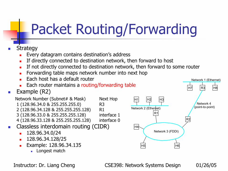
Packet Routing/ForwardingStrategy
Every datagram contains destination’s addressIf directly connected to destination network, then forward to hostIf not directly connected to destination network, then forward to some routerForwarding table maps network number into next hopEach host has a default routerEach router maintains a routing/forwarding table
Example (R2)Network Number (Subnet# & Mask) Next Hop1 (128.96.34.0 & 255.255.255.0) R32 (128.96.34.128 & 255.255.255.128) R13 (128.96.33.0 & 255.255.255.128) interface 14 (128.96.33.128 & 255.255.255.128) interface 0Classless interdomain routing (CIDR)
128.96.34.0/24128.96.34.128/25Example: 128.96.34.135
Longest match
R2
R1
H4
H5
H3H2H1
Network 2 (Ethernet)
Network 1 (Ethernet)
H6
Network 3 (FDDI)
Network 4(point-to-point)
H7 R3 H8
Instructor: Dr. Liang Cheng CSE398: Network Systems Design 01/26/05
Address TranslationMap IP addresses into physical addresses
Destination hostNext hop router
ARP (Address Resolution Protocol)Table of IP to physical address bindingsBroadcast request if IP address not in tableTarget machine responds with its physical addressTable entries are discarded if not refreshed

Instructor: Dr. Liang Cheng CSE398: Network Systems Design 01/26/05
Routing OverviewForwarding vs. routing
Forwarding: to select an output port based on the destination address and routing tableRouting: the process by which the routing table is built
Network as a graphGraph nodes are routersDefault routerGraph edges are linksCost: delay, $, …
Problem: find lowest cost path between two nodesFactors
Static topology (Wireless)Dynamic load
4
36
21
9
1
1D
A
FE
B
C

Instructor: Dr. Liang Cheng CSE398: Network Systems Design 01/26/05
Routing Algorithm ClassificationDecentralized information based routing
Router knows physically-connected neighbors, link costs to neighborsIterative process of computation, exchange of info with neighbors“Distance vector” algorithms
Global information based routingAll routers have complete topology, link cost info“Link state” algorithms

Instructor: Dr. Liang Cheng CSE398: Network Systems Design 01/26/05
OutlineRecapIPUDP and TCP (layer 4)Summary and homework

Instructor: Dr. Liang Cheng CSE398: Network Systems Design 01/26/05
Process-to-Process ChannelHost-to-host packet delivery service ⇒ process-to-process communication channelUnderlying best-effort network
Drop messagesRe-orders messagesDelivers duplicate copies of a given messageLimits messages to some finite sizeDelivers messages after an arbitrarily long delay
Expected end-to-end servicesGuarantee message deliveryDeliver messages in the same order they are sentDeliver at most one copy of each messageSupport arbitrarily large messagesSupport synchronizationAllow the receiver to flow control the senderSupport multiple application processes on each host
Instructor: Dr. Liang Cheng CSE398: Network Systems Design 01/26/05
UDP
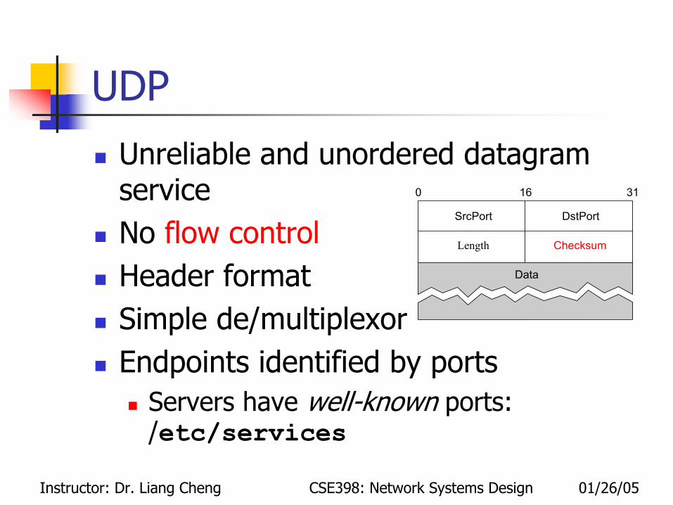
Unreliable and unordered datagram serviceNo flow controlHeader formatSimple de/multiplexorEndpoints identified by ports
Servers have well-known ports: /etc/services
SrcPort DstPort
Length Checksum
Data
0 16 31

Instructor: Dr. Liang Cheng CSE398: Network Systems Design 01/26/05
Stop-and-wait RetransmissionNode A
Set SN to 0Accept a packet from the next higher layer, assign number SN to the new packetTransmit the SNth packet in a segment containing SN in the sequence number field; if timeout then retransmitIf RN>SN, increase SN to RN and go to step 2
Node BSet RN to 0, then repeat step 2 and step 3An error-free segment from A with SN=RN, then release the received segment to the higher layer and increment RNAt arbitrary time, but within bounded delay after receiving any error-free data segment from A, transmit a segment to A containing RN in the request number field

Instructor: Dr. Liang Cheng CSE398: Network Systems Design 01/26/05
Stop-and-wait ARQ Protocol
0Node A
Node B
0 1
0Packets out
RN
SN
1 11
2
2
2
3
3
Instructor: Dr. Liang Cheng CSE398: Network Systems Design 01/26/05
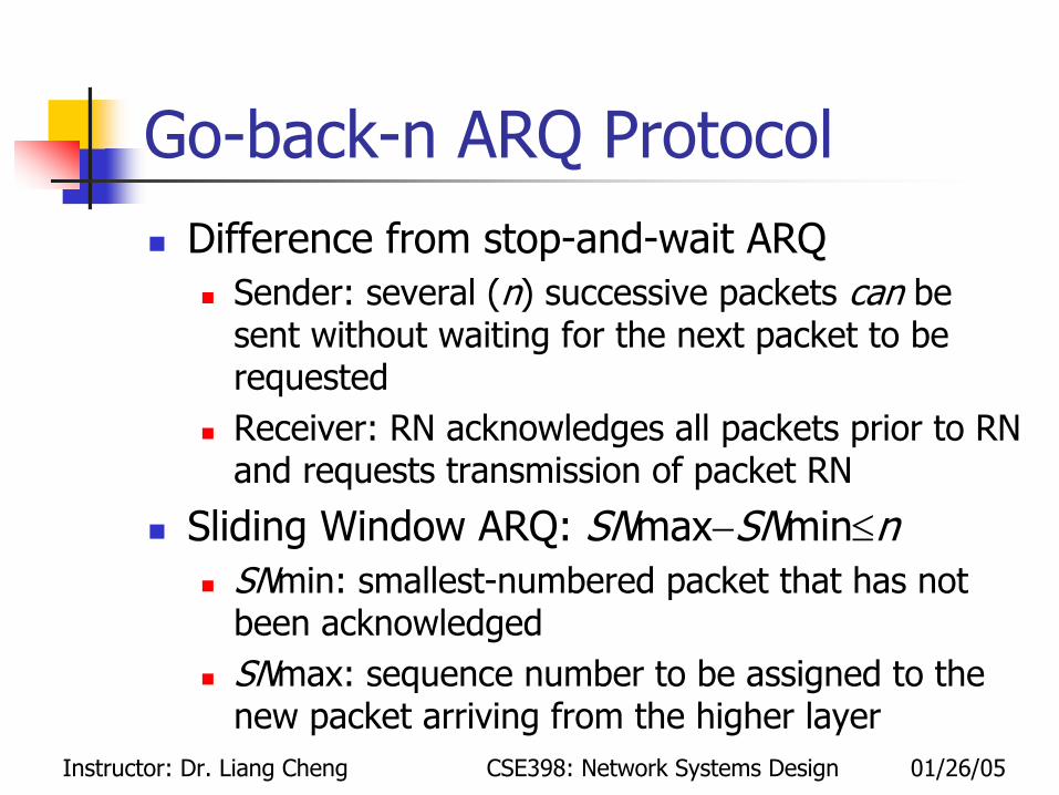
Go-back-n ARQ ProtocolDifference from stop-and-wait ARQ
Sender: several (n) successive packets can be sent without waiting for the next packet to be requestedReceiver: RN acknowledges all packets prior to RN and requests transmission of packet RN
Sliding Window ARQ: SNmax−SNmin≤nSNmin: smallest-numbered packet that has not been acknowledgedSNmax: sequence number to be assigned to the new packet arriving from the higher layer

Instructor: Dr. Liang Cheng CSE398: Network Systems Design 01/26/05
Go-back-n ARQ ProtocolNode A
Set the integer variable SNmax and SNmin to 0Do step 3,4,and 5 repeatedly in any orderIf SNmax< SNmin+n, and if a packet is available from the higher layer, accept the packet, assign number SNmax to it, and increment SNmaxIf an error-free packet is received from B with RN>SNmin, set SNmin=RNIf SNmin<SNmax and no packet is in transmission, choose SN, SNmin<SN<SNmax; transmit the SNth packet with SN. If timeout then retransmit the whole window
Node BSet the integer RN to 0 and repeat 2 and 3 foreverWhenever an error-free packet is received from A with SN=RN, release the received packet to the higher layer and increment RNAt arbitrary times, after receiving any error-free packet from A, transmit a packet to A with RN

Instructor: Dr. Liang Cheng CSE398: Network Systems Design 01/26/05
Go-back-n ARQ Protocol
iNode A
Node B
Window
t1[i,i+n-1]
…SN
RN
Packets out i
i+3
i+1 i+4i+3i+2 i+5
i+1 i+2
i+1 i+2
t2
X
t3[i+3,i+n+2]
i+5i+3 i+4
i+4i
Instructor: Dr. Liang Cheng CSE398: Network Systems Design 01/26/05
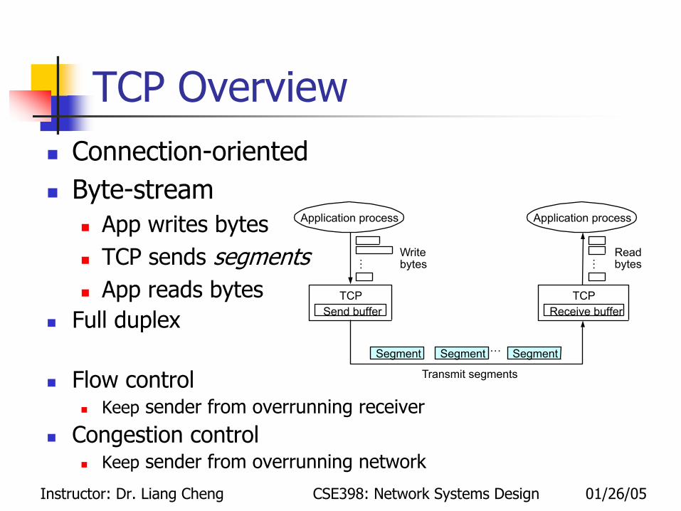
TCP OverviewConnection-orientedByte-stream
App writes bytesTCP sends segmentsApp reads bytes
Full duplex
Flow controlKeep sender from overrunning receiver
Congestion controlKeep sender from overrunning network
Application process
Writebytes
TCPSend buffer
Segment Segment Segment
Transmit segments
Application process
Readbytes
TCPReceive buffer
…… …

Instructor: Dr. Liang Cheng CSE398: Network Systems Design 01/26/05
Establish & Terminate Connection
Active participant(client)
Passive participant(server)
SYN, SequenceNum = x
SYN + ACK, SequenceNum = y,
ACK, Acknowledgment= y + 1
Acknowledgment = x + 1
Three-way handshake

Instructor: Dr. Liang Cheng CSE398: Network Systems Design 01/26/05
Flow ControlTCP segment formatConnection is identified by 4-tuple:
(SrcPort, SrcIPAddr, DsrPort, DstIPAddr)
Flow controlAcknowledgment, SequenceNum, AdvertisedWinow
FlagsSYN, FIN, RESET, PUSH, URG, ACK
Options (variable)
Data
Checksum
SrcPort DstPort
HdrLen 0 Flags
UrgPtr
AdvertisedWindow
SequenceNum
Acknowledgment
0 4 10 16 31
Sender
Data (SequenceNum)
Acknowledgment +AdvertisedWindow
Receiver
Instructor: Dr. Liang Cheng CSE398: Network Systems Design 01/26/05
Congestion Control
AIMDSlow startFast retransmit and fast recovery

Instructor: Dr. Liang Cheng CSE398: Network Systems Design 01/26/05
OutlineRecapIPUDP and TCPSummary and homework
Instructor: Dr. Liang Cheng CSE398: Network Systems Design 01/26/05
A Review Question
DHCPUDP or TCP?Unicast, broadcast, and/or multicast?

Instructor: Dr. Liang Cheng CSE398: Network Systems Design 01/26/05
DHCPDHCP (Dynamic Host Configuration Protocol)Save network administrators’ configuration efforts: address poolBoot: DHCPDISCOVER to 255.255.255.255Relay agentLease renew
DHCPrelay
DHCPserver
UDP unicast to server
Host
UD
P Br
oadc
ast

Instructor: Dr. Liang Cheng CSE398: Network Systems Design 01/26/05
Lab on 01/31
Traffic monitoring and throughput measurementLocation: PL112

Instructor: Dr. Liang Cheng CSE398: Network Systems Design 01/26/05
Homework (due on Jan. 31st before the class)
G00.00.00.00/2
F40.00.00.00/2
E80.00.00.00/1
DC4.68.00.00/14
CC4.60.00.00/12
BC4.5E.10.00/20
AC4.50.0.0/12
NextHopNetMaskLength2.2. The following table is a routing table using CIDR. Address bytes are in hexadecimal. The notation “/12” in C4.50.0.0/12 denotes a netmask with 12 leading 1 bits, that is FF.F0.00.00. Note that the last three entries covers every address and thus serve in lieu of a default route. State to what next hop the following will be delivered. (a) C4.5E.13.87 (b) C4.5E.22.09 (c) C3.41.80.02 (d) 5E.43.91.12 (e) C4.6D.31.2E (f) C4.6B.31.2E.